

Page 1
Page 1
SENECA s.r.l.
Sales: [email protected] (IT), [email protected] (Other)
This document is property of SENECA srl. Duplication and reprodution are forbidden, if not authorized. Contents of the present documentation refers to products and
USER MANUAL
Z-TWS4
Z-PASS2-S
S6001-RTU
Via Austria, 26 – 35127 – Z.I. CAMIN – PADOVA – ITALY
technologies described in it. All technical data contained in the document may be modified without prior notice Content of this documentation is subject to periodical
revision.
To use the product safely and effectively, read carefully the following instructions before use. The product must be used only for the use for which it was designed and
built. Any other use must be considered with full responsibility of the user. The installation, programmation and set-up is allowed only for authorized operators; these
ones must be people physically and intellectually suitable. Set up must be performed only after a correct installation and the user must perform every operation described
in the installation manual carefully. Seneca is not considered liable of failure, breakdown, accident caused for ignorance or failure to apply the indicated requirements.
Seneca is not considered liable of any unauthorized changes. Seneca reserves the right to modify the device, for any commercial or construction requirements, without
the obligation to promptly update the reference manuals.
Tel. +39.049.8705359 – 8705408 Fax. +39.049.8706287
Web site: www.seneca.it
Support: [email protected] (IT), [email protected] (Other)
MI003773
MI003770_121
Page 2

USER MANUAL – Z-TWS4/Z-PASS2-S/S6001-RTU
2
Table of contents
Table of contents ............................................................................................................................................... 2
1 Preliminary information / Informazioni preliminari .................................................................................. 6
2 Features ................................................................................................................................................... 10
3 Technical specifications ........................................................................................................................... 11
4 Electrical Connections ............................................................................................................................. 16
4.1 Z-TWS4, Z-TWS4-IO, Z-PASS2-S, Z-PASS2-S-R01, Z-PASS2-S-IO ....................................................... 16
4.1.1 Z-TWS4-IO Digital I/Os ............................................................................................................. 20
4.1.2 Z-PASS2-S-IO Digital I/Os ......................................................................................................... 20
4.2 S6001-RTU ....................................................................................................................................... 21
5 LEDs signaling .......................................................................................................................................... 25
5.1 Z-TWS4, Z-PASS2-S........................................................................................................................... 25
5.2 Z-PASS2-S-R01 ................................................................................................................................. 25
5.3 Z-PASS2-S-IO .................................................................................................................................... 27
5.4 Z-TWS4-IO ........................................................................................................................................ 28
5.5 S6001-RTU ....................................................................................................................................... 29
6 Discovering the IP address....................................................................................................................... 30
7 FTP/SFTP access ....................................................................................................................................... 32
8 StratON PLC ............................................................................................................................................. 33
8.1 Writing, downloading and running the first program ..................................................................... 33
8.1.1 Seneca libraries and templates installation............................................................................. 34
8.1.2 Creating a project for Seneca CPUs ......................................................................................... 38
8.1.3 Z-PASS2-S-IO profiles ............................................................................................................... 43
8.1.4 Z-TWS4-IO profile .................................................................................................................... 44
8.2 Energy Management Protocols ....................................................................................................... 45
8.3 StratON Redundancy ....................................................................................................................... 45
9 Ethernet Mode (Z-PASS2-S-R01/Z-PASS2-S-IO/Z-TWS4-IO) .................................................................... 46
10 VPN ...................................................................................................................................................... 48
10.1 “Single LAN” VPN ............................................................................................................................. 50
10.2 “Point-to-Point” VPN ....................................................................................................................... 51
11 Network Redundancy .......................................................................................................................... 52
12 Router .................................................................................................................................................. 53
13 Remote Connection Disable ................................................................................................................ 54
14 Auto-APN ............................................................................................................................................. 54
Page 3

USER MANUAL – Z-TWS4/Z-PASS2-S/S6001-RTU
3
15 M-Bus (ONLY Z-TWS4-IO and Z-PASS2-S-IO) ....................................................................................... 54
16 OPC Unified Architecture (OPC UA) protocol ...................................................................................... 55
17 Upgrading the firmware by USB pen ................................................................................................... 55
18 Web Configuration Pages .................................................................................................................... 56
18.1 Administrator pages ........................................................................................................................ 56
18.1.1 Main View ................................................................................................................................ 57
18.1.2 Network and Services .............................................................................................................. 58
18.1.3 Real Time Clock Setup ............................................................................................................. 69
18.1.4 VPN Configuration ................................................................................................................... 73
18.1.5 Router Configuration ............................................................................................................... 90
18.1.6 OPC UA Server Configuration .................................................................................................. 99
18.1.7 Users Configuration ............................................................................................................... 100
18.1.8 FW Upgrade ........................................................................................................................... 102
18.1.9 Configuration Management .................................................................................................. 111
18.1.10 Modbus TCP Client Configuration ..................................................................................... 114
18.1.11 Mobile Network ................................................................................................................. 116
18.1.12 DDNS Configuration ........................................................................................................... 130
18.1.13 Digital I/O Configuration .................................................................................................... 134
18.1.14 I/O View (S6001-RTU) ........................................................................................................ 140
18.1.15 FW Versions ....................................................................................................................... 143
18.1.16 Ethernet Interfaces ............................................................................................................ 145
18.1.17 Modbus Modules ............................................................................................................... 147
18.1.18 M-Bus Scan ........................................................................................................................ 149
18.1.19 M-Bus Configuration .......................................................................................................... 154
18.1.20 Data Logs ........................................................................................................................... 164
18.2 User pages ..................................................................................................................................... 168
18.2.1 Main View .............................................................................................................................. 169
18.2.2 Network and Services ............................................................................................................ 170
18.2.3 I/O View (S6001-RTU) ............................................................................................................ 173
18.3 Guest pages ................................................................................................................................... 174
19 Seneca StratON Library ...................................................................................................................... 177
19.1 Function Blocks .............................................................................................................................. 178
19.1.1 General FB behavior .............................................................................................................. 178
19.1.2 FTP_GET ................................................................................................................................. 178
Page 4

USER MANUAL – Z-TWS4/Z-PASS2-S/S6001-RTU
4
19.1.3 FTP_PUT ................................................................................................................................. 179
19.1.4 GET_ALARMS ......................................................................................................................... 180
19.1.5 GET_SMS ................................................................................................................................ 181
19.1.6 LINUX_SHELL .......................................................................................................................... 182
19.1.7 LINUX_SH_ASYNC .................................................................................................................. 182
19.1.8 MBUS_WRITE_RAW............................................................................................................... 183
19.1.9 MODEM_CTRL ....................................................................................................................... 184
19.1.10 MODEM_ONOFF ................................................................................................................ 185
19.1.11 MODEM_RESET ................................................................................................................. 185
19.1.12 PPP_CONNECT ................................................................................................................... 186
19.1.13 PPP_CONNECT_R2 ............................................................................................................. 187
19.1.14 PPP_STATUS....................................................................................................................... 189
19.1.15 PUT_ALARM ....................................................................................................................... 190
19.1.16 S7_DB_READ ...................................................................................................................... 191
19.1.17 S7_DB_WRITE .................................................................................................................... 192
19.1.18 SEND_MAIL ........................................................................................................................ 193
19.1.19 SEND_SMS ......................................................................................................................... 194
19.1.20 SERVICE_CTRL .................................................................................................................... 195
19.1.21 SET_ALARMS_STAT ............................................................................................................ 196
19.1.22 TIME_SYNC ........................................................................................................................ 197
19.1.23 UAC_CONNECT .................................................................................................................. 197
19.1.24 UAC_DISCONNECT ............................................................................................................. 198
19.1.25 UAC_READ ......................................................................................................................... 198
19.1.26 UAC_WRITE........................................................................................................................ 199
19.1.27 VPNBOX_STATUS ............................................................................................................... 200
19.2 Functions ....................................................................................................................................... 200
19.2.1 FM_WRITE_NCRLF ................................................................................................................. 201
19.2.2 TXBAPPENDFILE ..................................................................................................................... 201
19.2.3 GET_MIN_SINCE2K ................................................................................................................ 201
19.2.4 MBUS_READ_CTL................................................................................................................... 202
19.2.5 WDOG_KEEP_ALIVE ............................................................................................................... 203
19.2.6 WDOG_SET_TMO .................................................................................................................. 203
20 Z-NET4 ............................................................................................................................................... 204
21 Access to Straton variables ................................................................................................................ 205
Page 5

USER MANUAL – Z-TWS4/Z-PASS2-S/S6001-RTU
5
21.1 Shared Memory ............................................................................................................................. 205
21.2 C program example ....................................................................................................................... 206
21.3 CGI ................................................................................................................................................. 208
21.3.1 CGI “readVariable” ................................................................................................................ 209
21.3.2 CGI “writeVariable” ............................................................................................................... 209
22 Glossary ............................................................................................................................................. 210
Page 6

USER MANUAL – Z-TWS4/Z-PASS2-S/S6001-RTU
6
1 Preliminary information / Informazioni preliminari
WARNING!
IN NO EVENT WILL SENECA OR ITS SUPPLIERS BE LIABLE FOR ANY LOST DATA, REVENUE OR
PROFIT, OR FOR SPECIAL, INDIRECT, CONSEQUENTIAL, INCIDENTAL OR PUNITIVE DAMAGES,
REGARDLESS OF CAUSE (INCLUDING NEGLIGENCE), ARISING OUT OF OR RELATED TO THE USE OF
OR INABILITY TO USE Z-TWS4/Z-PASS2-S/S6001-RTU, EVEN IF SENECA HAS BEEN ADVISED OF
THE POSSIBILITY OF SUCH DAMAGES.
SENECA, ITS SUBSIDIARIES AND AFFILIATES COMPANY OR GROUP OF DISTRIBUTORS AND
SENECA RETAILERS NOT WARRANT THAT THE FUNCTIONS WILL MEET YOUR EXPECTATIONS, AND
THAT Z-TWS4/Z-PASS2-S/S6001-RTU, ITS FIRMWARE AND SOFTWARE WILL BE FREE FROM
ERRORS OR IT OPERATES UNINTERRUPTED.
SENECA SRL CAN MODIFY THE CONTENTS OF THIS MANUAL IN ANY TIME WITHOUT NOTICE TO
CORRECT, EXTEND OR INTEGRATING FUNCTION AND CHARACTERISTICS OF THE PRODUCT.
ATTENZIONE!
IN NESSUN CASO SENECA O I SUOI FORNITORI SARANNO RITENUTI RESPONSABILI PER
EVENTUALI PERDITE DI DATI ENTRATE O PROFITTI, O PER CAUSE INDIRETTE, CONSEQUENZIALI O
INCIDENTALI, PER CAUSE (COMPRESA LA NEGLIGENZA), DERIVANTI O COLLEGATE ALL' USO O
ALL' INCAPACITÀ DI USARE Z-TWS4/Z-PASS2-S/S6001-RTU, ANCHE SE SENECA È STATA AVVISATA
DELLA POSSIBILITÀ DI TALI DANNI.
SENECA, LE SUSSIDIARIE O AFFILIATE O SOCIETÀ DEL GRUPPO O DISTRIBUTORI E RIVENDITORI
SENECA NON GARANTISCONO CHE LE FUNZIONI SODDISFERANNO FEDELMENTE LE ASPETTATIVE
E CHE Z-TWS4/Z-PASS2-S/S6001-RTU, IL SUO FIRMWARE E SOFTWARE SIA ESENTE DA ERRORI O
CHE FUNZIONI ININTERROTTAMENTE.
SENECA SRL PUO’ MODIFICARE IL CONTENUTO DI QUESTO MANUALE IN QUALUNQUE
MOMENTO E SENZA PREAVVISO AL FINE DI CORREGGERE, ESTENDERE O INTEGRARE
FUNZIONALITA’ E CARATTERISTICHE DEL PRODOTTO.
Page 7

USER MANUAL – Z-TWS4/Z-PASS2-S/S6001-RTU
7
Date
Revision
Notes
06/09/2016
07
- Chapter "Features": new features forZ-PASS2-S-R01
- Chapter "LEDs signalling": new par. " Z-PASS2-S-R01"
- New chapter "Ethernet Mode (Z-PASS2-S-R01)"
- Chapter: "Discovering the IP address": network parameters setting
- Chapter "Upgrading the firmware by a USB pen": revision
- Par. "Web Configuration Pages/Administrator pages": changed
paragraphs:
- "Main View"
- "Network and Services"
- "Router Configuration"
- "FW Upgrade"
new paragraphs:
- "VPN Configuration/OpenVPN Client/LED signalling (Z-PASS2-S-R01)"
- "VPN Configuration/VPN Box/LED signalling (Z-PASS2-S-R01)"
- Par. "Web Configuration Pages/User pages"
changed paragraphs:
- "Main View"
- "Network and Services"
11/01/2017
08
- Renamed “Z-PASS2-S-1” → ”, “Z-PASS2-S-R01”
- Chapter “Discovering the IP address”: discovery working on both LAN
and WAN interfaces
- New chapter “Network Redundancy”
- Paragraph “Main View” revision (also for “User Pages”)
- Paragraph “Network and Services”: added “DNS Mode” parameter
and Network Redundancy parameters; changed some default values
(also for “User Pages”)
- Paragraph “Real Time Clock Setup”: added “Central Europe” time
zone value
- Paragraph "VPN Configuration/OpenVPN Client": revision into "VPN
Configuration/OpenVPN”; added packet/byte counters description
- Paragraph "VPN Configuration/VPN Box”: added packet/byte counters
description
- Paragraph “Mobile Network”: added packet/byte counters
description
- Paragraph “Router Configuration”: Port Mapping parameters no more
disabled when “Use Local Addresses” is ON
- Paragraph “Users Configuration”: added “guest” user credentials
- New paragraph “Ethernet Interfaces”
- New paragraph “Modbus Modules”
- New paragraph “Data Logs”
- New paragraph “Guest Pages”
- StratON FBs and Functions, new paragraphs: GET_ALARMS,
PUT_ALARM, SET_ALARMS_STAT, FM_WRITE_NCRLF, TXBAPPENDFILE,
GET_MIN_SINCE2K
- Chapter Z-NET4: added note to “Remote Control Functions”
01/03/2017
09
- New paragraph “Configuration Management”
- PLC application name shown in the web pages header
- “Use Local Address through VPN” parameter: “ON” option always
available
- Paragraph “Network and Services” (Admin and User): changed default
value for “Default Gateway” and “DNS Server” parameters; “Default
Gateway” always in the WAN subnet, in LAN/WAN mode; “DHCP on
LAN” disabled, in LAN/WAN mode
Page 8

USER MANUAL – Z-TWS4/Z-PASS2-S/S6001-RTU
8
- OpenVPN, Configuration File: added rules on “dev” and “log” options
- StratON FBs and Functions, new paragraphs: S7_DB_READ,
S7_DB_WRITE
23/05/2017
10
- Chapter "Features": new features for Z-PASS2-S-IO
- New “LEDs signaling” sub-paragraph for IO HW revision
- New chapter “Remote Access Disable”
- New chapter “Auto-APN”
- Paragraph “Network and Services”: added screen-shots for “IO”
version; added “COM1/Mode” parameter
- Paragraph “VPN Box”: added “License Limit Reached” error reason
- Paragraph “FW Upgrade”: changed “Stop TWS Services” pop-up
- Paragraph “Configuration Management”: added “Save Debug Logs”
feature
- Paragraph “Mobile Network”: added “APN Mode” parameter
- New paragraph “Digital I/O Configuration”
- Paragraph “PPP_CONNECT”: changes for “Auto-APN”
- StratON FBs and Functions, new paragraphs: PPP_CONNECT_R2,
VPNBOX_STATUS, WDOG_KEEP_ALIVE, WDOG_SET_TMO
02/08/2017
11
- Chapter “Technical Specifications”: added features for Z-PASS2-S-IO
modem
- Paragraph “LEDs signaling”/IO: added info about modem “STAT “ LED
- Chapter “VPN”: added description of Layer 2 and Layer 3 VPN
- Paragraph “VPN Configuration/VPN Box”: changes related to L2 VPN
and info about connected user; added L2 VPN figure
- Deleted paragraph “Updating the StratON application by a USB pen”
- Chapter “Upgrading the firmware…”: added notes about LEDs blinking
- Paragraph “Main View” (admin): updated figure
- Paragraph “Network and Services”: added info about new Web Server
and File Transfer parameters; updated figures
- Paragraph “Real Time Clock Setup”: updated figure
- Paragraph “Router Configuration”: changed default value for “Allow
Access through Mobile Public IP Address” parameter
- Paragraph “Configuration Management”: added info about zip
archive; updated figures
- Paragraph “Mobile Network”: updated figures
- “Remote Access Disable” → “Remote Connection Disable”
06/10/2017
12
- Changed “-R02” → “-IO”
- Chapters “Features”, “Technical Specifications”: note about GPS
module and antenna
- Chapter “Electrical Connections”: added sub-paragraph for Z-PASS2-SIO Digital I/Os
- New sub-paragraph “Z-PASS2-S-IO profiles”
- Paragraphs “Main View”, “Network and Services”: updated figures
- Paragraph “Real Time Clock Setup”: added figure with new time zones
- Paragraph “VPN Box”: updated first figure
- Paragraph “Router Configuration”: updated figures
- Paragraph “Users Configuration”: updated figure
- Paragraph “FW Upgrade”: updated figures
- Paragraph “Configuration Management”: added table about save
option and archive contents; updated figure
- New sub-paragraph “Factory reset by USB pen”
- Paragraph “Mobile Network”: added info and figure about “GPS
Location”; updated some figures
- Paragraph “Digital I/O Configuration”: added info and figure about
“Local Alarm”
Page 9

USER MANUAL – Z-TWS4/Z-PASS2-S/S6001-RTU
9
- New paragraph “FW Versions”
- Deleted “DHCP on LAN” parameter
- Paragraph “Network and Services” (user): updated figures
30/11/2017
13
- Paragraph “Router Configuration”: parameter “Access through Mobile
Public IP Address” changed to “Mobile Network Firewall”
- Paragraph “Mobile Network”: changes related to “Operator
Selection” and PIN handling
- New paragraph “DDNS Configuration”
- Paragraphs “Main View” and “Guest pages”: “RESET” button renamed
to “RESTART”; updated figures
- Chapter “Remote Connection Disable”: added “Security Level 4 (SMS
Service)”
- Paragraph “Digital I/O Configuration”: added “Security Level 4 (SMS
Service)” ; updated figures
- Paragraph “FW Versions”: updated figure
- StratON FBs, new paragraph: SERVICE_CTRL
- Deleted references to Z-MODEM-3G
18/01/2018
14
- Chapter “Features”: added Z-PASS2-S-IO-4G product
- Chapter “Technical specifications”: updated info about modem
- Removed “None” value of “Security Level / Service Disable”
parameter.
15/03/2018
15
- Removed CTS signal from COM1 port (Z-TWS4, Z-PASS2-S)
- Added parts related to Z-TWS4-IO
30/07/2018
16
(FW rel. SW002940_336)
- Paragraph “Router Configuration”: new “Ethernet Bandwidth
Limitation” parameter; updated figures
28/09/2018
17
(FW rel. SW002940_340)
- New chapter “M-Bus”
- New web page paragraph “Modbus TCP Client Configuration”
- New web page paragraph “M-Bus Diagnostics”
- New FB paragraphs MBUS_GET_DATA, MBUS_GET_INFO,
MBUS_READ_DATA, MBUS_WRITE_RAW
10/10/2018
18
(FW rel. SW002940_341)
- Paragraph “M-Bus Diagnostics” reviewed
23/10/2018
19
(FW rel. SW002940_342)
- Paragraph “M-Bus Diagnostics” reviewed
20/03/2019
20
(FW rel. SW002940_344)
-Modified chapter “M-Bus Diagnostics” in “M-Bus Scan”
-Added Chapter “M-Bus Configuration”
- new function MBUS_READ_CTL
- Deleted FB: MBUS_READ_DATA, MBUS_GET_DATA, MBUS_GET_INFO
05/04/2019
21
(FW rel. SW00290_350)
-Added Chapter “OPC-UA”
-new FB
UAC_CONNECT
UAC_DISCONNECT
UAC_READ
UAC_WRITE
Page 10

USER MANUAL – Z-TWS4/Z-PASS2-S/S6001-RTU
10
2 Features
Z-TWS4, Z-PASS2-S and S6001-RTU are programmable, communication oriented PLCs.
The Z-TWS4/Z-PASS2-S/S6001-RTU StratON™ PLC is programmable according to the IEC 61131-3 standard, by means
of the StratON development environment.
All three devices provide the following features:
OpenVPN connectivity
full configuration by means of an integrated web site
FW upgrade, that can be performed locally, by means of a USB pen, or remotely, through the web site
Z-PASS2-S and S6001-RTU integrate a 3G HSPA modem.
S6001-RTU is equipped with a rich set of analog and digital inputs/outputs.
Z-PASS2-S, S6001-RTU and Z-TWS4 (when connected to an external modem) can be used as a Router, routing packets
between the WAN (Mobile Network) and the LAN (Ethernet).
All three devices are based on a 32bits ARM9 processor, equipped with the Linux operating system (Linux kernel
2.6.28).
Z-PASS2-S-R01 is a new version of the Z-PASS2-S product, providing the following new features:
the two available Ethernet ports can be configured as two fully separated network interfaces (“LAN” and
“WAN”), whereas in the older versions they could only work as ports of an Ethernet switch; the user can
choose if the two ports shall work in “LAN/WAN” mode or “Switch” mode, by means of a new configuration
parameter (“Ethernet Mode”);
there are 4 more LEDs, providing information about the “Ethernet Mode” and the VPN functionalities.
Z-TWS4-IO is a new version of the Z-TWS4 product, providing the following new features:
one digital input which can be used to disable remote connection to the device
one digital output which goes HIGH when the device is remotely accessed
one digital output which can also be used as a remote command
one configurable digital input/output, which can also be used as a local alarm
a new set of LEDs
COM1 RS232/RS485 mode set by software (configuration parameter), instead of HW DIP switch
Z-PASS2-S-IO is a new version of the Z-PASS2-S product, providing the following new features:
one digital input which can be used to disable remote connection to the device
one digital output which goes HIGH when the device is remotely accessed
one digital input which can also be used as a local alarm
one digital output which can also be used as a remote command
two configurable digital inputs/outputs
a new set of LEDs
COM1 RS232/RS485 mode set by software (configuration parameter), instead of HW DIP switch
a new penta-band 3G+ modem, which also features a GPS module
Z-PASS2-S-IO-4G is a new version of the Z-PASS2-S-IO product, providing a new 4G LTE Cat.1 modem, instead of the
3G+ modem.
Page 11

USER MANUAL – Z-TWS4/Z-PASS2-S/S6001-RTU
11
COMMUNICATION PORTS (Z-TWS4/Z-PASS2-S)
RS 485
Baud rate: maximum 115 Kbps, minimum 110 bps
COM 4 (screw terminals 4-5-6)
COM 2 (screw terminals 1-2-3 or IDC10 connector)
COM 1 (removable 4 pin connector, as an alternative to RS232)
RS 232
Baud rate: maximum 115 Kbps, minimum 110 bps
COM 1 (removable 4 pin connector, as an alternative to RS485)
CAN
CAN bus port 2.0A and 2.0B
Baud rate: maximum 500 Kbps, minimum 20 Kbps
(screw terminals 10-11-12 or IDC10 connector)
available only in Z-TWS4
Ethernet 1 and Ethernet 2
Ethernet 10/100 Mbps
Two RJ45 connectors on front-panel
Maximum connection length 100 m
In Z-PASS2-S-R01/Z-PASS2-S-IO/Z-TWS4-IO, the two ports can work either as
LAN/WAN ports (ETH1=LAN, ETH2=WAN) or ports of an Ethernet switch.
In Z-TWS4/Z-PASS2-S, the two ports can work only as ports of an Ethernet
switch.
USB #1 HOST
Plug-in: USB type A
USB #2 HOST
Plug-in: micro USB (available only in Z-TWS4)
COMMUNICATION PORTS (S6001-RTU)
RS 485
Baud rate: maximum 115 Kbps, minimum 110 bps
COM 4 (screw terminals 54-55-56)
COM 2 (screw terminals 57-58-59)
NOTE 1:
in the following chapters, the term “Device” will be used when describing features or characteristics that are available
in all three products.
NOTE 2:
in the following chapters, any reference to 3G modem/connection applies also to 4G modem/connection.
3 Technical specifications
Page 12

USER MANUAL – Z-TWS4/Z-PASS2-S/S6001-RTU
12
RS 232
Baud rate: maximum 115 Kbps, minimum 110 bps
COM 1 (DB9 male connector)
Optional Bus for future extensions
screw terminals 60-61-62
Ethernet
Ethernet 10/100 Mbps
RJ45 connector
Maximum connection length 100 m
USB #1 HOST
Plug-in: USB type A
CPU AND MEMORY
Microprocessor
ARM 9, 32 bits, 400 MHz
Memories
64 Mbytes of RAM
1 Gbyte of FLASH
8 Kbytes of FeRAM, split in 2 partitions (4 Kbytes each) for redundancy
Slot for external memory
Micro SD card: max 32 Gbytes
I/O CPU (S6001-RTU)
Microprocessor
8 bits, 24 MHz
3G+ MODEM (Z-PASS2-S/S6001-RTU)
HSPA Modem
14.4 Mbps in downlink, 5.76 Mbps in uplink
Slot for SIM card
Mini SIM with push-push connector
3G+ MODEM (Z-PASS2-S-IO)
Speed
HSPA+: max 14.4 Mbps DL, max 5.76 Mbps UL
UMTS: max 384 Kbps (DL), max 384 Kbps (UL)
EDGE: max 236.8 Kbps (DL), max 236.8 Kbps (UL)
GPRS: max 85.6 Kbps (DL), max 85.6 Kbps (UL)
GNSS
GPS/GLONASS
16 GPS channels
14 GLONASS channels
Accuracy <1.5m CEP-50 @ Open Sky
Approvals
RoHS Compliant, CE/GCF/Vodafone (Europe), DoC (Russia), FCC/PTCRB/AT&T
(North America), RCM (Australia), ICASA (South Africa), SRRC/NAL/OFCA
(China), JATE & TELEC (Japan), NCC (Taiwan), KC/SKT (Korea), IC/Rogers
(Canada), Anatel (Brazil), NBTC (Thailand)
Slot for mini SIM
Mini SIM with push-push connector
Page 13

USER MANUAL – Z-TWS4/Z-PASS2-S/S6001-RTU
13
4G (LTE Cat. 1) MODEM (Z-PASS2-S-IO-4G)
Speed
LTE FDD: max 10 Mbps (DL), max 5Mbps (UL)
LTE TDD: max 8.96 Mbps (DL), max 3.1 Mbps (UL)
DC-HSPA+: max 42Mbps (DL), max 5.76 Mbps (UL)
UMTS: max 384 Kbps (DL), max 384 Kbps (UL)
EDGE: max 296 Kbps (DL), max 236.8 Kbps (UL)
GPRS: max 107 Kbps (DL), max 85.6 Kbps (UL)
GNSS
GPS/GLONASS/BeiDou/Galileo/QZSS
Approvals
RoHS Compliant, CE/GCF/Vodafone (Europe), FCC/PTCRB/AT&T/Verizon*
(North America), RCM/Telstra (Australia), JATE/TELEC/DOCOMO* (Japan), NCC
(Taiwan), KC/SKT/KT*/LGU+* (Korea), IC/Rogers (Canada), Anatel (Brazil),
CCC/SRRC/NAL (China)
*= Under Development
Slot for mini SIM
Mini SIM with push-push connector
POWER SUPPLY (Z-TWS4/Z-PASS2-S)
Power supply
11..40 Vdc or 19..28 Vac @ 50..60 Hz
Consumption
Typical 4 W @ 24 Vdc; Max 6 W
POWER SUPPLY (S6001-RTU)
Power supply
24 Vac/dc ± 15% @ 50/60Hz
Consumption
10 VA max , 6 VA typical
ENVIRONMENTAL CONDITIONS (Z-TWS4/Z-PASS2-S)
Temperature
-20..+55 °C
Humidity
30..90 % @ 40 °C not condensing
Storage temperature
-20..+85 °C
Protection degree
IP20
ENVIRONMENTAL CONDITIONS (S6001-RTU)
Temperature
-10..+65 °C
Humidity
10..90 % not condensing
Storage temperature
-40..+85 °C
Protection degree
IP20
CONNECTIONS (Z-TWS4/Z-PASS2-S)
Connections
Removable 3 way screw terminals, 5.08 pitch
Page 14

USER MANUAL – Z-TWS4/Z-PASS2-S/S6001-RTU
14
Rear IDC10 connector for DIN 46277 rail
Removable 4 pin connector
Two RJ45 connectors
Type A USB connector and micro USB connector (only in Z-TWS4)
Plug in: micro SD card
Two SMA antenna connectors:
- for Main and Diversity antennas (only in Z-PASS2-S, Z-PASS2-S-R01)
- for 3G and GPS antennas (only in Z-PASS2-S-IO)
CONNECTIONS (S6001-RTU)
Connections
Removable screw terminals
DB9 male connector
RJ45 connector
Type A USB connector
Plug in: micro SD card
Two SMA antenna connectors, for Main and Diversity antennas
BOX / DIMENSIONS (Z-TWS4/Z-PASS2-S)
Dimensions
Z-TWS4: L: 100 mm; H: 112 mm; W: 35 mm
Z-PASS2-S: L: 100 mm; H: 112 mm; W: 53 mm
Case
Nylon 6 with 30% fiberglass field, self-extinguishing class V0, black color
WEIGHT / DIMENSIONS (S6001-RTU)
Dimensions
190 mm x 160 mm x 105 mm
Weight
600 g
INPUTS / OUTPUTS (Z-TWS4-IO)
Digital Inputs
Max. number of channels: 2
Voltage: OFF<4V ON>8V; Max. Current (Vout+): 20mA
Current absorbed: 3mA at 12VC; 6mA at 24VC
Digital Outputs
Max. number of channels: 3
Voltage (+Vext): 10 – 24VC
Max. current delivered: 400mA
INPUTS / OUTPUTS (Z-PASS2-S-IO)
Digital Inputs
Max. number of channels: 4
Voltage: OFF<4V ON>8V; Max. Current (Vout+): 20mA
Current absorbed: 3mA at 12VC; 6mA at 24VC
Page 15

USER MANUAL – Z-TWS4/Z-PASS2-S/S6001-RTU
15
Digital Outputs
Max. number of channels: 4
Voltage (+Vext): 10 – 24VC
Max. current delivered: 400mA
INPUTS / OUTPUTS (S6001-RTU)1
Analog inputs
4, current, 0..20 mA
resolution: 12 bit
accuracy: += 0.3% of full scale
input impedance: 50 Ω
Analog outputs
1, current, 0..20 mA
1, voltage, 0..10 Vdc
resolution: 12 bit
accuracy: += 0.3% of full scale
output load: current: <= 500 Ω, voltage: >= 1 kΩ
Digital inputs
15, PNP, with optoisolation
ON current > 4 mA, OFF current < 3 mA
Digital outputs
8, SPDT relays
max peak current: 3 A
operating current: 2 A
operating voltage: 250 Vac
minimum load: 0.5 W
isolation: 3 kV
Liquid level control inputs
conductive liquid level switch, 2 channels
adjustable sensitivity
Standard
Frequency/Feature
Z-PASS2-S, Z-PASS2-S-
R01, S001-RTU
Z-PASS2-S-IO
Z-PASS2-S-IO-4G
GSM
GSM 850 MHz
OK
OK
EGSM 900 MHz
OK
OK
OK
DCS 1800 MHz
OK
OK
OK
PCS 1900 MHz
OK
OK
WCDMA
WCDMA 800 MHz
OK
WCDMA 850 MHz
OK
OK
WCDMA 900 MHz
OK
OK
OK
WCDMA 1900 MHz
OK
WCDMA 2100 MHz
OK
OK
OK
LTE
LTE 800 DD
OK
LTE 850
OK
LTE 900
OK
LTE 1800
OK
LTE 2100
OK
LTE 2600
OK
HSPA
HSDPA
OK
OK
HSUPA
OK
OK
HSPA+ OK
DC-HSPA+
OK
DRX
Receiver Diversity
OK
1
The following table shows which frequency bands are supported by the modem available in Z-PASS2-S, Z-PASS2-S-R01,
S6001-RTU, Z-PASS2-S-IO and Z-PASS2-S-IO-4G products.
For more detailed information about S6001-RTU I/Os, see S6001-RTU Installation Manual.
Page 16
USER MANUAL – Z-TWS4/Z-PASS2-S/S6001-RTU
16
4 Electrical Connections
4.1 Z-TWS4, Z-TWS4-IO, Z-PASS2-S, Z-PASS2-S-R01, Z-PASS2-S-IO
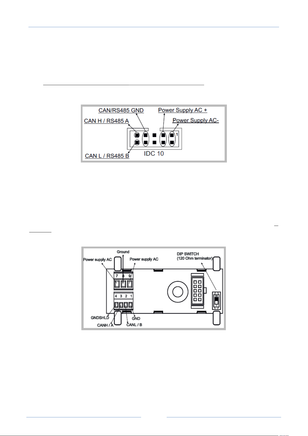
Power Supply and Modbus interface are available by using the bus for the Seneca DIN rail, by the rear IDC10 connector
or by Z-PC-DINAL1-35 accessory for Z-TWS4, Z-PC-DINAL2-52.5-17 for Z-PASS2-S. The following picture shows the
meaning of the IDC10 connector pins.
Power supply is available only from the rear connector for Z-TWS4, while:
Z-TWS4-IO can be powered also through 17-18 screw terminals;
Z-PASS2-S/ZPASS2-S-R01/ZPASS2-S-IO can be powered also through 14-15 screw terminals.
If Z-PC-DINAL1-35 or Z-PC-DINAL2-52.5-17 accessory is used, the power supply signals and communication signals may
be provided by the terminals block into the DIN rail support. In the following figure the meaning and the position of
the terminal blocks are shown. The DIP-switch that sets the 120 Ω terminator is used only for CAN communication (ZTWS4 only).
GNDSHLD: shield to protect the connection cables against interference (recommended).
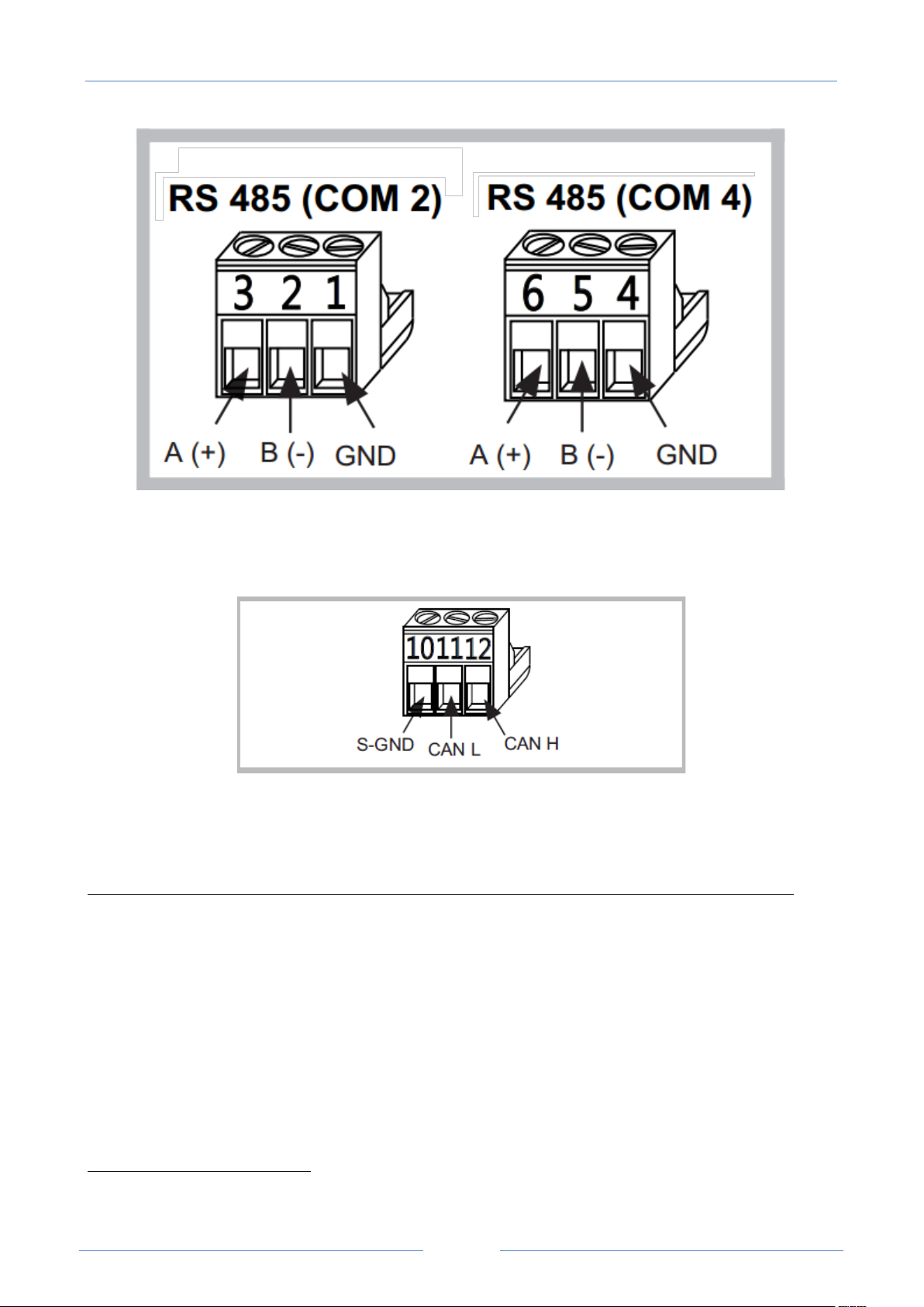
The Device has two RS 485 serial ports for Modbus communication: COM 4 and COM 2. The RS485 connection for
COM 2 can be set up by means of the corresponding screw terminals or by the IDC10 connector. On Z-TWS4, to select
RS 485 on IDC10 connector, put the SW1 DIP-switch on OFF position; on Z-PASS2-S, no operation is needed.
Page 17
USER MANUAL – Z-TWS4/Z-PASS2-S/S6001-RTU
17
2
The Z-TWS4 has a CAN port available on screw terminals 10-11-12. As an alternative, the connection can be set up on
the IDC10 connector. To select CAN port on IDC10 connector, put the SW1 DIP-switch on ON position.
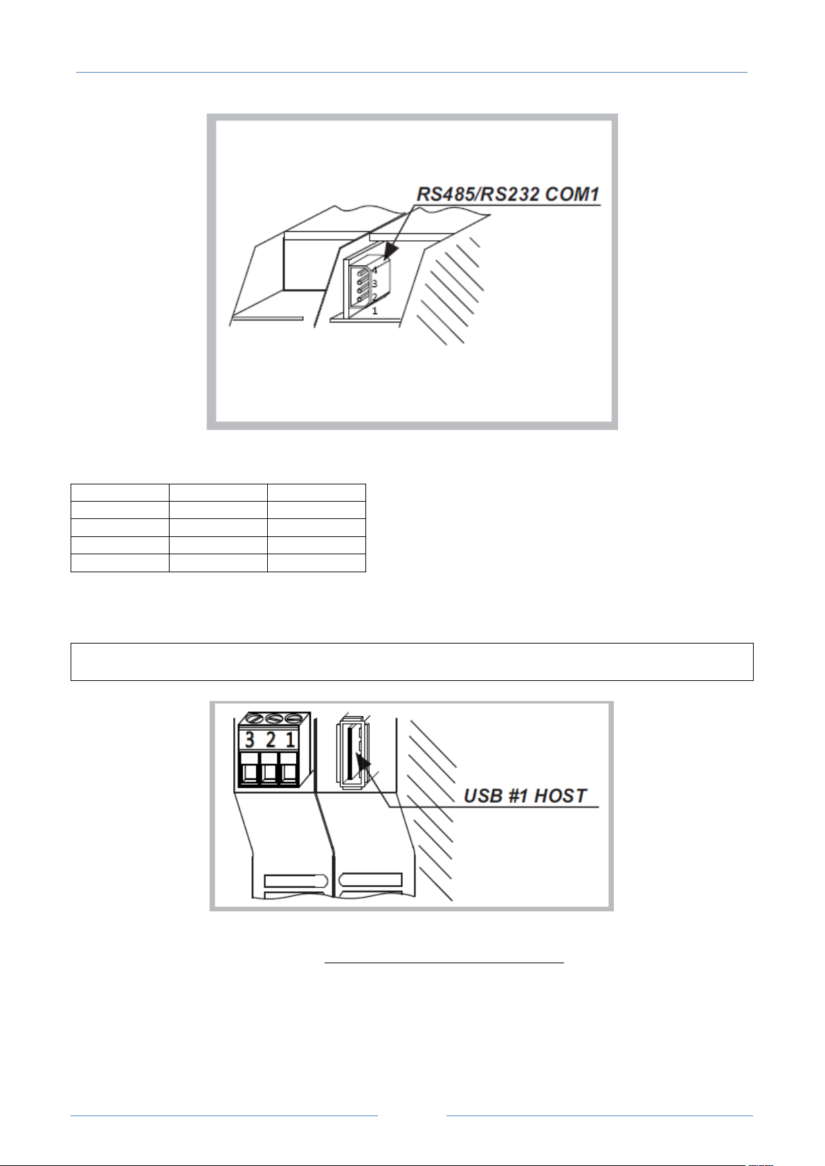
Through a removable 4 pin connector, the Device provides a serial RS232 port or, as an alternative, a third RS485 port.
In order to select the RS232 port on the removable 4 pin connector, put the SW2 DIP-switch on ON position; to select
the RS485 port on the removable 4 pin connector, put the SW2 DIP-switch on OFF position2.
In Z-TWS4-IO/Z-PASS2-S-IO, the mode (RS485/RS232) of this port is set as a parameter in software configuration.
The cable length for the RS232 interface must be less than 3 meters.
While in Z-TWS4 the SW2 DIP-switch position can be changed by the user, in Z-PASS2-S the DIP-switch is internal and
its position is permanently set in the factory.
Page 18
USER MANUAL – Z-TWS4/Z-PASS2-S/S6001-RTU
18
Pin
RS232
RS485
1 (bottom)
- - 2
Tx B 3
Rx A 4 (top)
GND
GND
The connector pin-out is given in the following table:
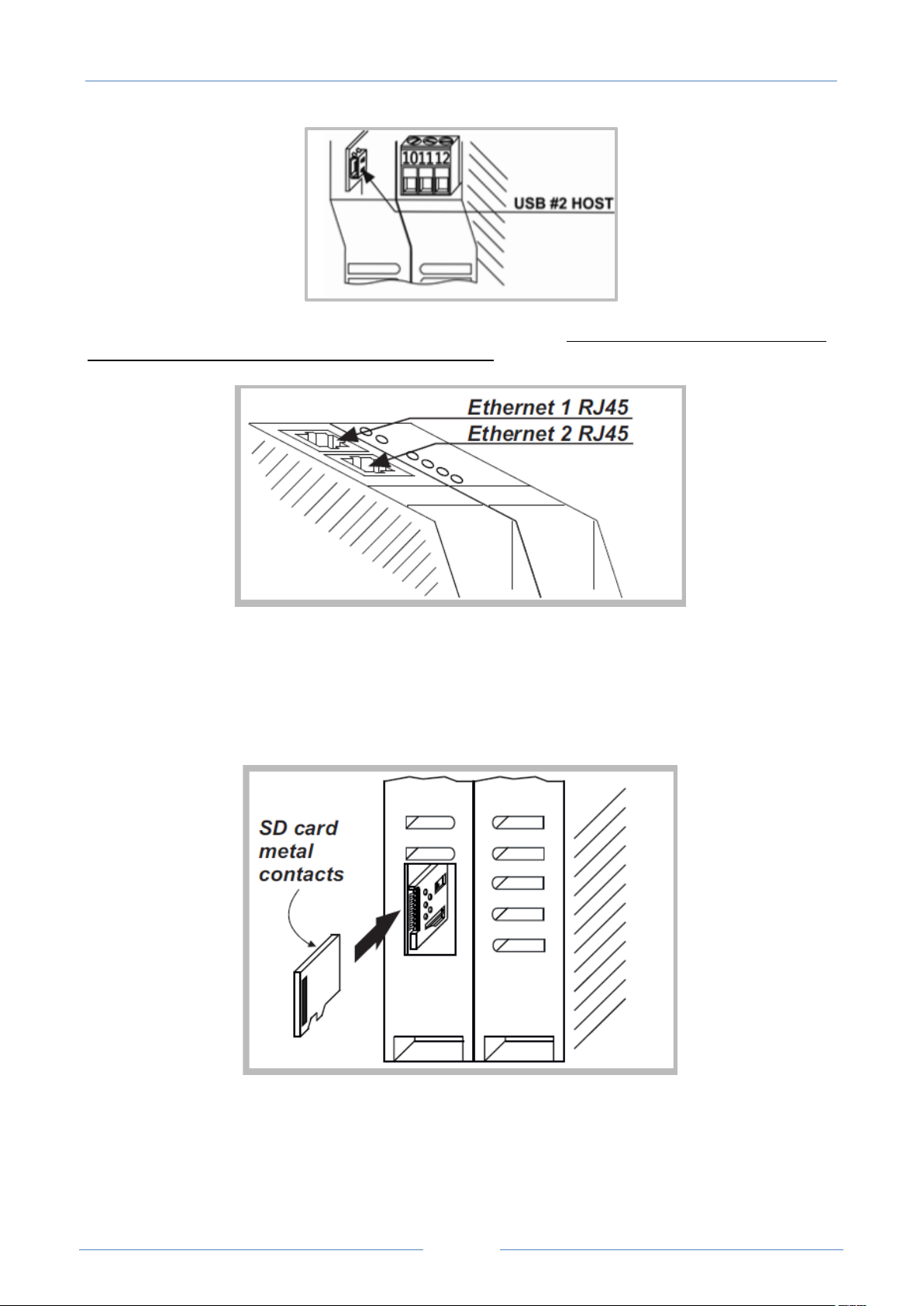
The Device has a USB HOST type A connector, that can be used as an additional serial port (using a Seneca S117P1, for
example) or to connect an external USB memory; this is used for FW upgrade (see chapter 17).
Please note that, on this USB port, the “hotplug” feature is not available; so, after plugging the USB device, it is
necessary to power off/on the Z-TWS4/Z-PASS2-S to let it detect the USB device.
The Z-TWS4 also has a second USB HOST connector, with micro-USB plug-in, that can be used to connect a USB device
by means of a “Micro USB to USB” adapter; this port is no more available in Z-TWS4-IO.
Page 19
USER MANUAL – Z-TWS4/Z-PASS2-S/S6001-RTU
19
The Device has two Ethernet ports with RJ45 connectors on the front panel. The two ports are internally connected in
HUB/SWITCH mode. The two ports have the same MAC Address.
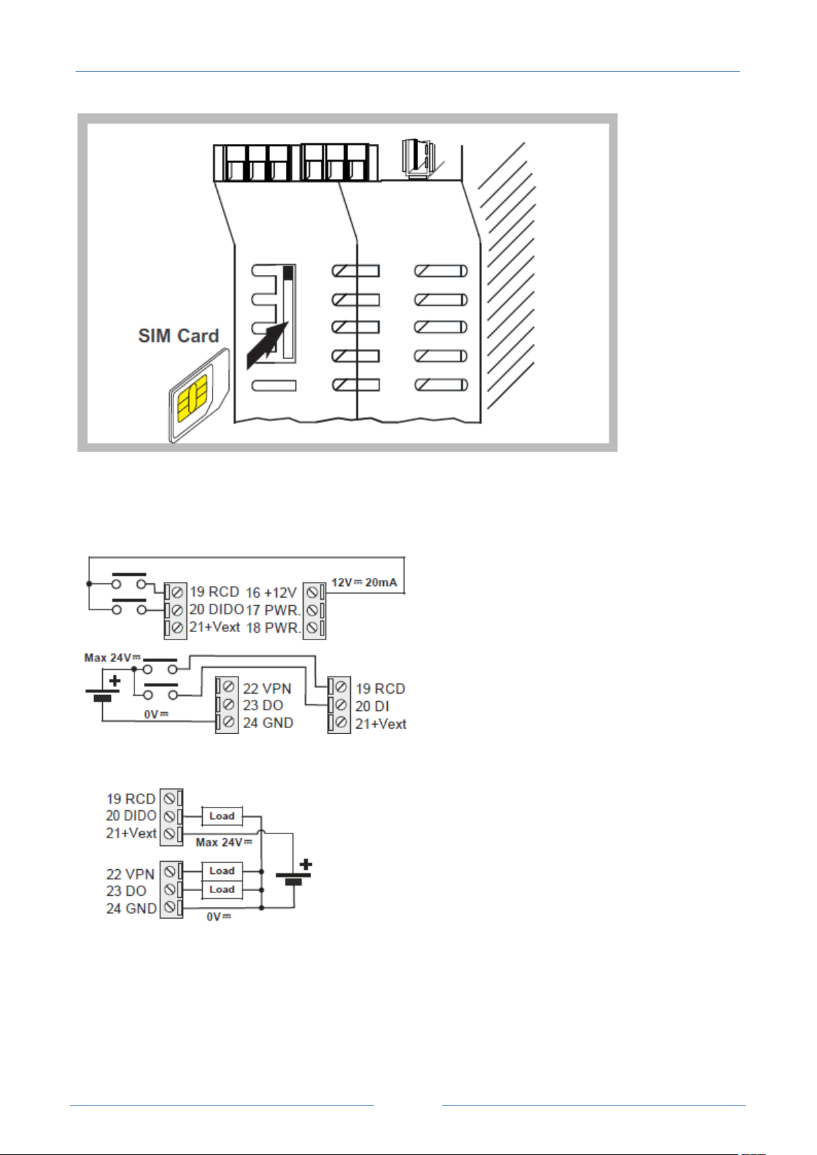
The Device has a plug-in connector for micro SD card placed in the side part of the case.
To insert the SD card into the connector, be sure that the SD card is oriented with metal contacts facing towards left
(with reference to the figure).
The SD card can be of any class.
The Z-PASS2-S has a slot for SIM card, placed on the side of the case. Before pushing the SIM card into this slot, please
be sure that the SIM card golden contacts are facing towards right (please see the figure below).
Page 20
USER MANUAL – Z-TWS4/Z-PASS2-S/S6001-RTU
20
4.1.1 Z-TWS4-IO Digital I/Os
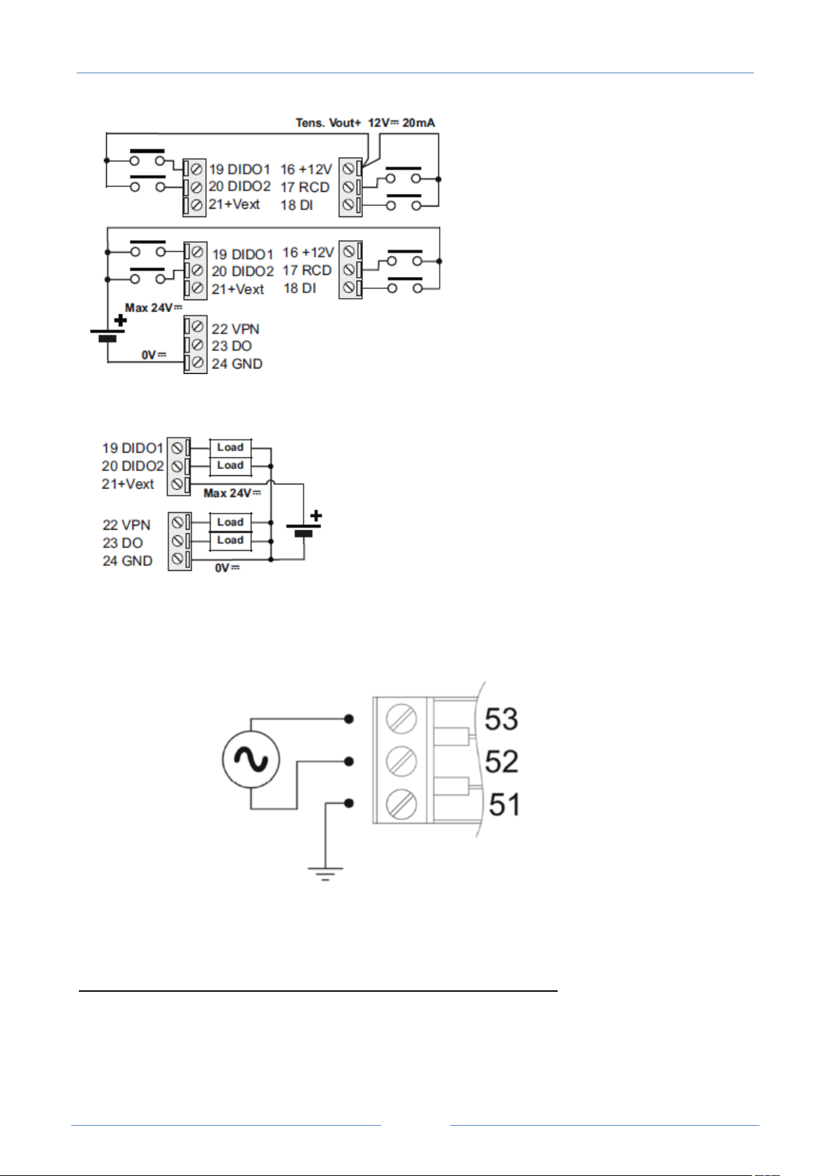
In Z-TWS4-IO, the electrical connections for the Digital Inputs shall be arranged as in the following figures.
The electrical connections for the Digital Outputs shall be arranged as in the following figure.
4.1.2 Z-PAS S 2-S-IO Digital I/Os
In Z-PASS2-S-IO, the electrical connections for the Digital Inputs shall be arranged as in the following
figures.
Page 21
USER MANUAL – Z-TWS4/Z-PASS2-S/S6001-RTU
21
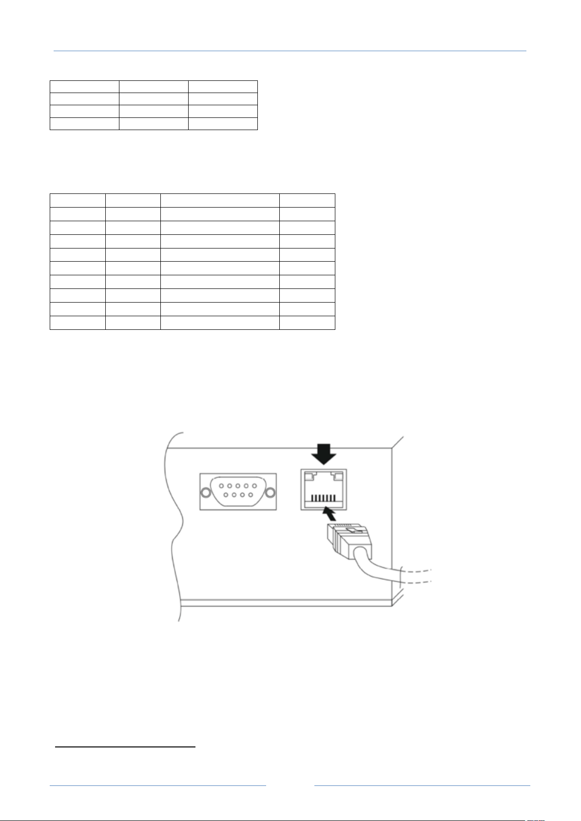
The electrical connections for the Digital Outputs shall be arranged as in the following figure.
4.2 S6001-RTU
Power supply must be connected to screw terminals 52 and 53. The supply voltage must be 24 ± 15 %
Vac/dc (any polarity).
Upper limits must not be exceeded to avoid serious damage to the device. It is necessary to protect the
power supply source against any failure of the device by means of an appropriately sized fuse.
S6001-RTU has two RS485 serial ports (COM2 and COM4) available on removable screw terminals, as
specified in the following table.
Page 22
USER MANUAL – Z-TWS4/Z-PASS2-S/S6001-RTU
22
Signal
COM2
COM4
GND
57
54
B
58
55 A 59
56
Pin
Name
Description
IN/OUT
1
DCD
Data carrier detect
In
2
RXD
Receive data
In 3 TXD
Transmit data
Out
4
DTR
Data terminal ready
Out 5 SG
Signal ground
6 DSR
Data set ready
In 7 RTS
Request to send
Out 8 CTS
Clear to send
In
9
RI
Ring indicator
In
3
An RS232 serial port with full handshaking signals is available on DB9 male connector on the left side of
S6001-RTU. Use the CS-DB9F-DB9F cable3 to connect RS232 devices.
Signals on DB9 connector are listed in the table below.
An optional communication bus is available on removable screw terminals 60,61,62, for future extensions.
S6001-RTU has 1 USB port which is an USB HOST with connector type “A”, suitable to connect, for example,
a mass storage (e.g.: a USB pen) with maximum consumption of 300 mA @ 5 Vdc.
An Ethernet port is available on the left side of S6001-RTU on an RJ45 connector.
An SD card slot is available, near the optional bus screw terminals; SD cards with storage capacity up to 32
GB can be used.
A SIM card slot, with a push-push connector, is available; 3V mini SIM cards can be used.
Two SMA antenna connectors are available, for Main and Diversity antennas.
The CS-DB9F-DB9F cable is supplied on request.
Page 23
USER MANUAL – Z-TWS4/Z-PASS2-S/S6001-RTU
23
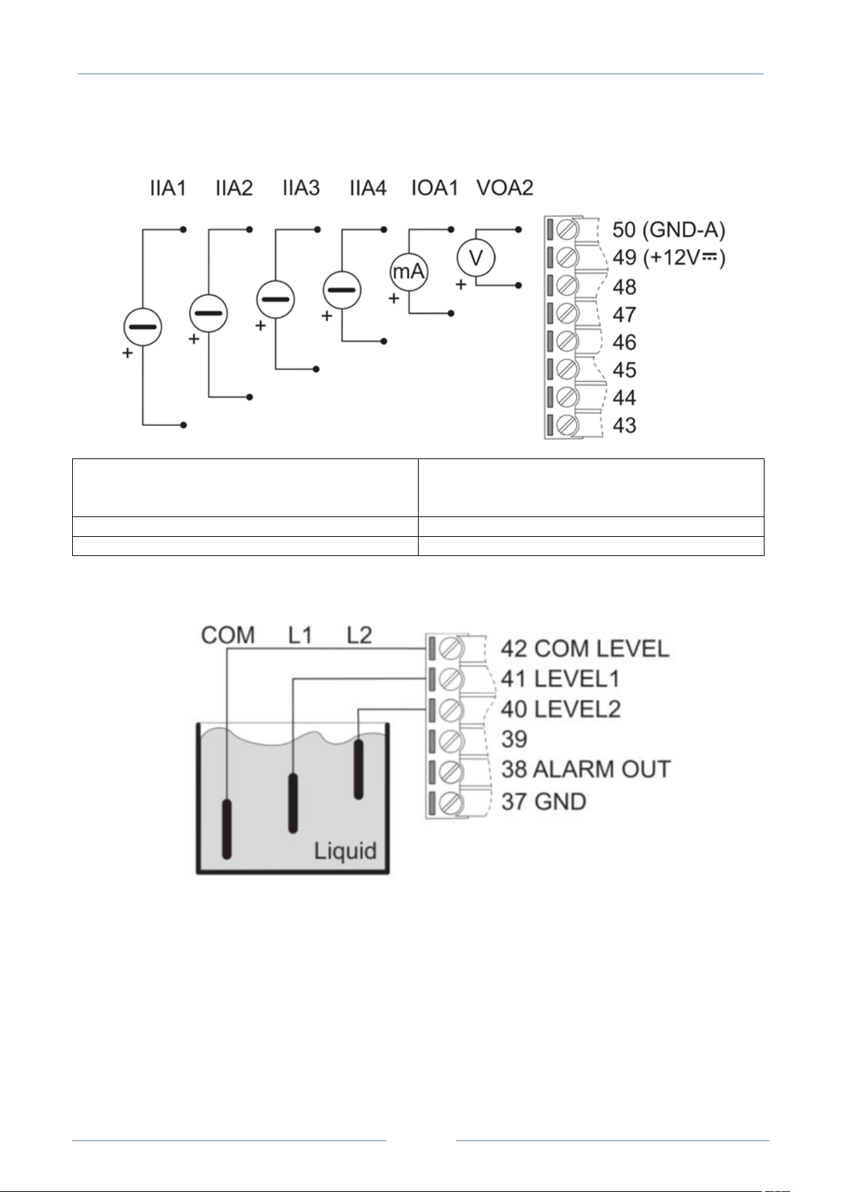
4 analog current inputs (0-20 mA)
Four active sensors are available from 43 to 46
screw terminals. Screw terminal 49 is a supply
voltage (+12 Vdc) for passive current sensor.
1 analog current output (0-20 mA)
Available between 47 and 50 screw terminals.
1 analog voltage output (0-10 Vdc)
Available between 48 and 50 screw terminals.
Analog inputs and outputs are available on screw terminals 43-50, as shown in the following figure and
table.
The Liquid Level Inputs are available on screw terminals 40-42, as shown in the following figure.
The analog level signals from screw terminals 40, 41, 42 can be used to control the level of liquid in a tank.
The supply voltage (12 Vdc @ 50mA) from screw terminals 38 and 37 can be used to connect, for example,
an acoustic alarm. Screw terminal 39 must not be connected.
Page 24
USER MANUAL – Z-TWS4/Z-PASS2-S/S6001-RTU
24
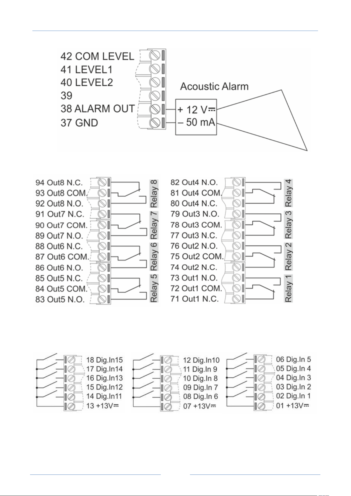
The 8 digital outputs (relays) are available on screw terminals 71-94, as shown in the following figure.
Eight SPDT relays are available to control, for example, external pumps. The operating voltage is 250 Vdc @
2 A.
The 15 digital inputs are available on screw terminals 1-18, as shown in the following figure.
All digital inputs are PNP type with optoisolation.
Page 25

USER MANUAL – Z-TWS4/Z-PASS2-S/S6001-RTU
25
LED
Status
Meaning
PWR Green
ON
The module is powered on
RUN Red
Blinking
The module is ready for use
LINK1 Yellow
ON
OFF
Ethernet 1 connection detected
Ethernet 1 connection absent
ACT1 Green
Blinking
OFF
There is data activity (Ethernet 1)
There is no data activity (Ethernet 1)
LINK2 Yellow
ON
OFF
Ethernet 2 connection detected
Ethernet 2 connection absent
ACT2 Green
Blinking
OFF
There is data activity (Ethernet 2)
There is no data activity (Ethernet 2)
RX1-2-4 Red
Blinking
ON
OFF
Data reception (COM 1-2-4)
Check the connection (COM 1-2-4)
No data reception (COM 1-2-4)
TX1-2-4 Red
Blinking
ON
OFF
Data transmission (COM 1-2-4)
Check the connection (COM 1-2-4)
No data transmission (COM 1-2-4)
3G PWR Green
(Z-PASS2-S only)
ON
The 3G Modem is powered on
STAT Yellow
(Z-PASS2-S only)
ON
Slow Blinking
Fast Blinking
Not registered on GSM network
Registered on GSM network
Mobile Network connection active
LED
Status
Meaning
PWR Green
ON
The module is powered on
RUN Red
Blinking
The module is ready for use
LAN/WAN
ON
The Ethernet ports are working in “LAN/WAN” mode
5 LEDs signaling
5.1 Z-TWS4, Z-PASS2-S
5.2 Z-PASS2-S-R01
Page 26

USER MANUAL – Z-TWS4/Z-PASS2-S/S6001-RTU
26
Yellow
OFF
-
SWITCH Green
ON
OFF
The Ethernet ports are working in “Switch” mode
-
VPN Yellow
ON
Blinking
OFF
VPN connection is working properly
VPN connection is not working properly
VPN functionality is disabled or
VPN Box/Point-to-Point functionality is enabled but no client is connected or
VPN Box/Single LAN functionality is enabled but the Device is not configured
yet
SERV Green
ON
Blinking
OFF
VPN Box “SERVICE” connection is working properly
VPN Box “SERVICE” connection is not working properly
VPN Box functionality is disabled
RX1-2-4 Red
Blinking
ON
OFF
Data reception (COM 1-2-4)
Check the connection (COM 1-2-4)
No data reception (COM 1-2-4)
TX1-2-4 Red
Blinking
ON
OFF
Data transmission (COM 1-2-4)
Check the connection (COM 1-2-4)
No data transmission (COM 1-2-4)
3G PWR Green
ON
The 3G Modem is powered on
STAT Yellow
ON
Slow Blinking
Fast Blinking
Not registered on GSM network
Registered on GSM network
Mobile Network connection active
LED
Status
Meaning
ETH1-2 Green
ON
OFF
Ethernet 1-2 connection detected
Ethernet 1-2 connection absent
ETH1-2 Yellow
Blinking
OFF
There is data activity (Ethernet 1-2)
There is no data activity (Ethernet 1-2)
Ethernet Connector LEDS
Page 27

27
LED
Status
Meaning
PWR Green
ON
The module is powered on
RUN Green
Blinking
The module is ready for use
DIDO1 Green
ON
OFF
Configurable Digital Input/Output 1 state is HIGH
Configurable Digital Input/Output 1 state is LOW
DIDO2 Green
ON
OFF
Configurable Digital Input/Output 2 state is HIGH
Configurable Digital Input/Output 2 state is LOW
DI Green
ON
OFF
Digital Input state is HIGH
Digital Input state is LOW
DO Green
ON
OFF
Digital Output state is HIGH
Digital Output state is LOW
RCD Green
ON
OFF
Remote Connection is disabled
Remote Connection is enabled
VPN Green
ON
Blinking
OFF
VPN connection is working properly
VPN connection is not working properly
VPN functionality is disabled or
VPN Box/Point-to-Point functionality is enabled but no client is connected or
VPN Box/Single LAN functionality is enabled but the Device is not configured
yet
LAN/WAN
Green
ON
OFF
The Ethernet ports are working in “LAN/WAN” mode
The Ethernet ports are working in “Switch” mode
SERV Green
ON
Blinking
OFF
VPN Box “SERVICE” connection is working properly
VPN Box “SERVICE” connection is not working properly
VPN Box functionality is disabled
RX2-4 Green
Blinking
ON
OFF
Data reception (COM 2-4)
Check the connection (COM 2-4)
No data reception (COM 2-4)
TX2-4 Green
Blinking
ON
Data transmission (COM 2-4)
Check the connection (COM 2-4)
5.3 Z-PASS2-S-IO
USER MANUAL – Z-TWS4/Z-PASS2-S/S6001-RTU
Page 28

28
OFF
No data transmission (COM 2-4)
3G PWR Green
ON
The 3G Modem is powered on
STAT Yellow
Slow blinking
(200 ms OFF,
1800 ms ON)
Slow blinking
(1800 ms OFF,
200 ms ON)
Fast blinking
(125 ms OFF, 125
ms ON)
Searching for GSM network
Registered on GSM network
Data transfer is ongoing
LED
Status
Meaning
ETH1-2 Green
ON
OFF
Ethernet 1-2 connection detected
Ethernet 1-2 connection absent
ETH1-2 Yellow
Blinking
OFF
There is data activity (Ethernet 1-2)
There is no data activity (Ethernet 1-2)
LED
Status
Meaning
PWR Green
ON
The module is powered on
RUN Green
Blinking
The module is ready for use
DIDO Green
ON
OFF
Configurable Digital Input/Output state is HIGH
Configurable Digital Input/Output state is LOW
DO Green
ON
OFF
Digital Output state is HIGH
Digital Output state is LOW
RCD Green
ON
OFF
Remote Connection is disabled
Remote Connection is enabled
VPN Green
ON
Blinking
OFF
VPN connection is working properly
VPN connection is not working properly
VPN functionality is disabled or
VPN Box/Point-to-Point functionality is enabled but no client is connected or
Ethernet Connector LEDS
USER MANUAL – Z-TWS4/Z-PASS2-S/S6001-RTU
5.4 Z-TWS4-IO
Page 29

USER MANUAL – Z-TWS4/Z-PASS2-S/S6001-RTU
29
VPN Box/Single LAN functionality is enabled but the Device is not configured
yet
LAN/WAN
Green
ON
OFF
The Ethernet ports are working in “LAN/WAN” mode
The Ethernet ports are working in “Switch” mode
SERV Green
ON
Blinking
OFF
VPN Box “SERVICE” connection is working properly
VPN Box “SERVICE” connection is not working properly
VPN Box functionality is disabled
RX2-4 Green
Blinking
ON
OFF
Data reception (COM 2-4)
Check the connection (COM 2-4)
No data reception (COM 2-4)
TX2-4 Green
Blinking
ON
OFF
Data transmission (COM 2-4)
Check the connection (COM 2-4)
No data transmission (COM 2-4)
LED
Status
Meaning
ETH1-2 Green
ON
OFF
Ethernet 1-2 connection detected
Ethernet 1-2 connection absent
ETH1-2 Yellow
Blinking
OFF
There is data activity (Ethernet 1-2)
There is no data activity (Ethernet 1-2)
Group
Number
Colour
Status
Meaning
Digital Inputs
1,2,3,4,5,6,7,8
9,10,11,12,13,14,15
Green
ON
OFF
High
Low
Digital Outputs
1,2,3,4,5,6,7,8
Red
ON
OFF
Closed
Open
3G Power Signal
2,3,4,5,6
Yellow
OFF
ON
6 ON = Max
1
Blinking
ON
1 Blinking = Min
Comm. Port COM2
RX, TX
Red
Blinking
RS485 activity
Red
Fixed ON
Verify connection
Comm. Port COM4
RX, TX
Red
Blinking
RS485 activity
Red
Fixed ON
Verify connection
Ethernet Connector LEDS
5.5 S6001-RTU
Frontal LEDS
Page 30

USER MANUAL – Z-TWS4/Z-PASS2-S/S6001-RTU
30
Run
1
Red
Blinking
Run
Level switch
L1, L2
Green
OFF, OFF (value 0)
ON, OFF (value 1)
ON, ON (value 2)
Under min level
Between min and
max levels
Over max level
LED
Status
Meaning
3G PWR Green
ON
The 3G Modem is powered on
STAT Yellow
ON
Slow Blinking
Fast Blinking
Not registered on GSM network
Registered on GSM network
Mobile Network connection active
Following are some further notes about LED behavior:
at power on, during the bootstrap phase, all LEDS, except for the COM PORT LEDs, are ON; when
the system is fully operational, RUN LED is blinking
when Straton application is not running, all LEDS, except for the COM PORT LEDs, are blinking
3G PWR SIG LED 1 is blinking, synchronously with RUN LED, in the following situations:
o GSM/3G network is not available (or signal level is too low)
o SIM is not inserted
Modem LEDS
6 Discovering the IP address
Z-TWS4/Z-PASS2-S/S6001-RTU devices come out of the factory with the default 192.168.90.101 IP address
on the Ethernet network interface.
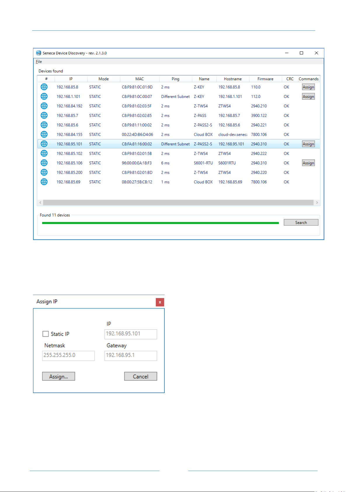
If this address is changed, and forgotten, it can be retrieved by running the “Seneca Device Discovery”
(SDD) application, as shown in the following figure:
Page 31
USER MANUAL – Z-TWS4/Z-PASS2-S/S6001-RTU
31
This application shows the IP address, MAC address, FW version and some other useful information, for
every Z-TWS4/Z-PASS2-S/S6001-RTU device (and other Seneca products) found in the LAN.
Moreover, by clicking on the “Assign” button, it is possible to change the network configuration parameters
of a device, as shown in the following figure:
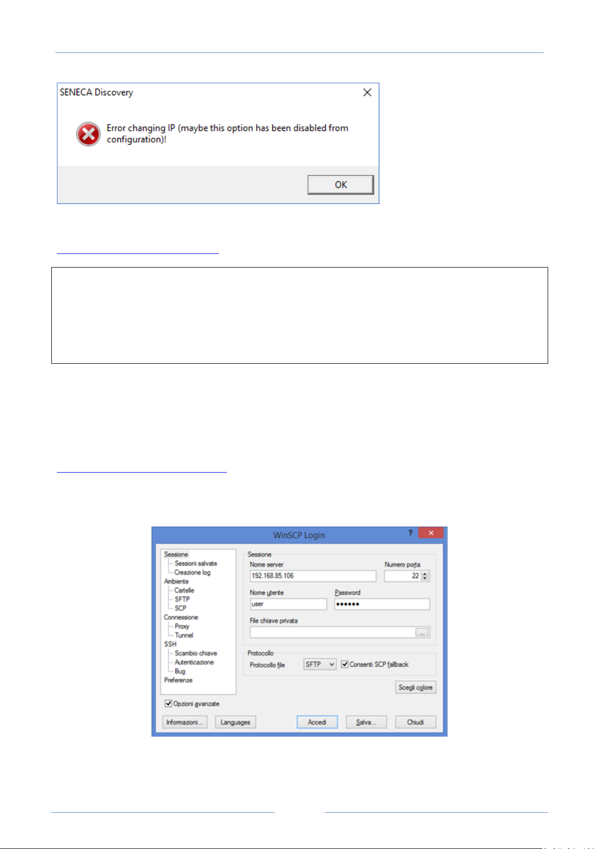
For security reasons, this feature can be disabled on the Device (see paragraph 18.1.2); in this case, the
following error message is shown, after clicking on the “Assign” button”.
Page 32
USER MANUAL – Z-TWS4/Z-PASS2-S/S6001-RTU
32
The SDD can be easily installed by running the installer program available at the following link:
http://www.seneca.it/products/sdd
NOTE:
- when the Device is working in “Switch” mode, the IP Address shown by the SDD is the same regardless of
the Ethernet port which the PC running the SDD is connected to;
- when the Device is working in “LAN/WAN” mode, the IP Address shown by the SDD is the LAN IP Address
when the PC is connected to the LAN port, the WAN IP Address when the PC is connected to the WAN port;
moreover, the network configuration parameter changes apply to the relevant port.
7 FTP/SFTP access
To easily access the Device by means of FTP/SFTP, you can use the WINSCP™ program; you can free
download WINSCP™ from:
http://winscp.net/eng/download.php
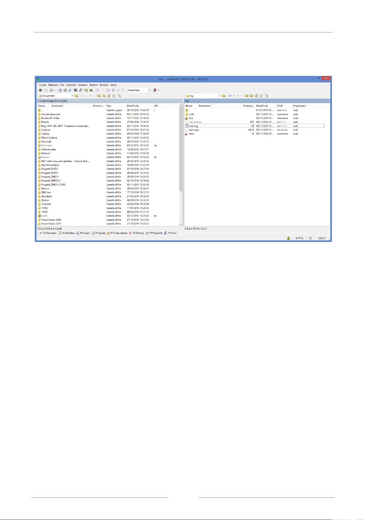
You must set the connection as in the following figure (the screenshot shows a connection to the
192.168.85.106 IP address):
The credentials (username and password) are those (“user”, “123456”) set for the “FTP USER” (see “Users
Configuration” web page in paragraph 18.1.7).
Page 33
USER MANUAL – Z-TWS4/Z-PASS2-S/S6001-RTU
33
After clicking the “Access” button, you will get a new window, as in the following screenshot; on the right,
you can copy and delete files directly to/from the Device.
The WinSCP program can be used both as an FTP or SFTP client to transfer files to/from the Device; just
select “FTP” or “SFTP” protocol in the “WinSCP Login” window; normally, it’s better to use SFTP, since it
provides a secure (i.e. encrypted) service.
8 StratON PLC
Z-TWS4/Z-PASS2-S/S6001-RTU StratON PLC provides the full support for IEC 61131-3 PLC Standard; an
Integrated Development Environment (IDE) is available for Windows™ PCs.
The StratON IDE includes several tools such as: a fieldbus configuration tool, an analog signal editor and
program editors compliant with the five languages of the IEC 61131-3 Standard: Sequential Function Chart
(SFC), Function Block Diagram (FBD), Ladder Diagram (LD), Structured Text (ST), Instruction List (IL).
With StratON IDE, it’s simple to write, download and debug IEC 61131-3 code.
8.1 Writing, downloading and running the first program
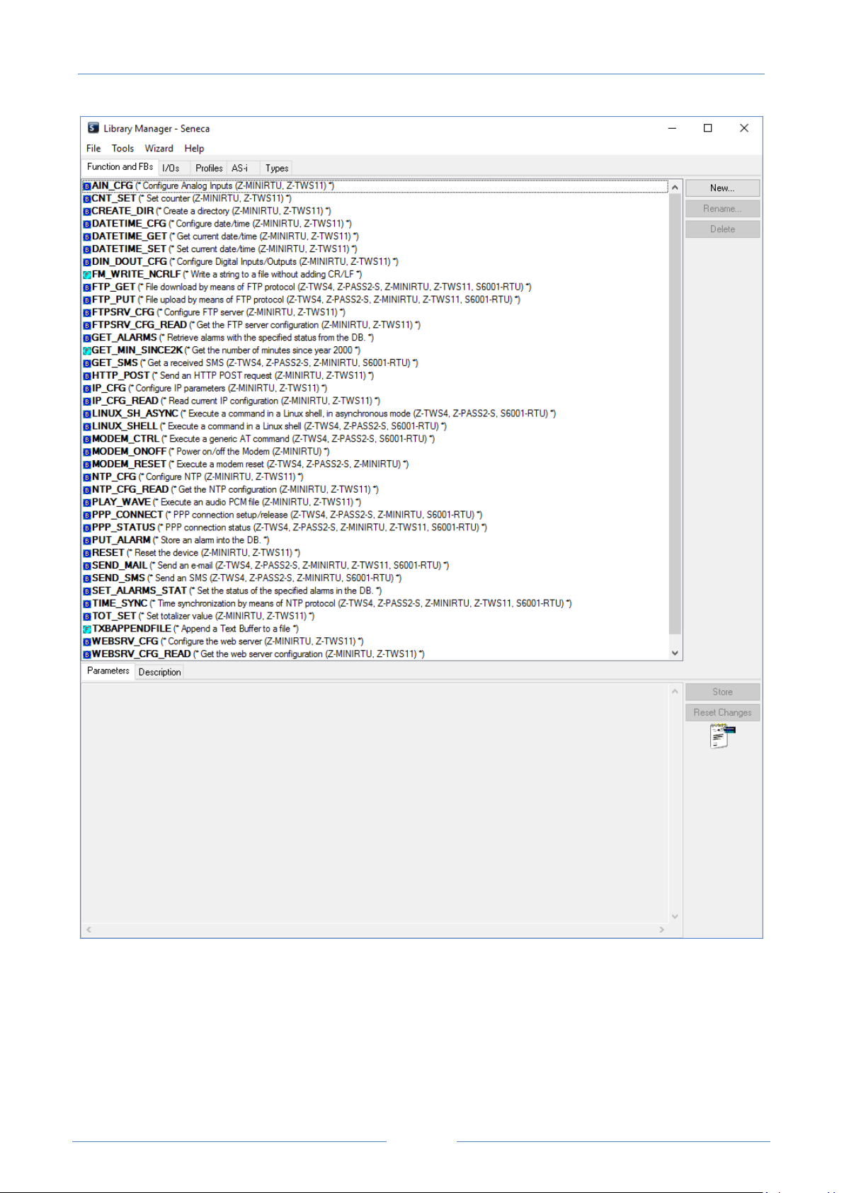
To let the PLC developer easily create StratON applications for Seneca CPUs, the following libraries are
available:
a Function Block (FB) and Functions library, which provides some frequently used functionalities,
particularly related to communication and data transfer tasks, compiled in the CPU firmware; the
direct use of these FBs and functions is targeted at skilled PLC developers (a detailed description of
the FBs and Functions is given in chapter 19);
a “Profiles” library, which provides access to the CPU I/Os by means of “profiled” variables; this is
needed for S6001-RTU and Z-PASS2-S-IO CPUs;
Page 34
USER MANUAL – Z-TWS4/Z-PASS2-S/S6001-RTU
34
a “User Defined Function Block” (UDFB) library, in ST language, which simplifies the use of the
above FBs, providing a simpler and “higher level” access to their functionalities.
Furthermore, two project templates are available for Z-PASS2-S and S6001-RTU CPUs, respectively.
An installer program, called “Seneca StratON Package setup”, is available which automatically installs the
above Seneca libraries and templates. The installer can also be used to install the StratON IDE and Z-NET4
SW (see chapter 20).
The installer is available at the following link:
http://www.seneca.it/products/seneca-straton-package
If, for some reasons, the installer can’t be run, the above libraries and templates can be installed manually
as described in the following sub-paragraph.
8.1.1 Sen eca libraries and templates instal l at ion
The following steps are needed to integrate the Seneca libraries and templates in the StratON IDE.
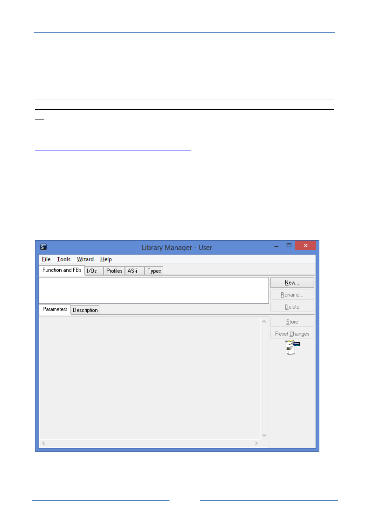
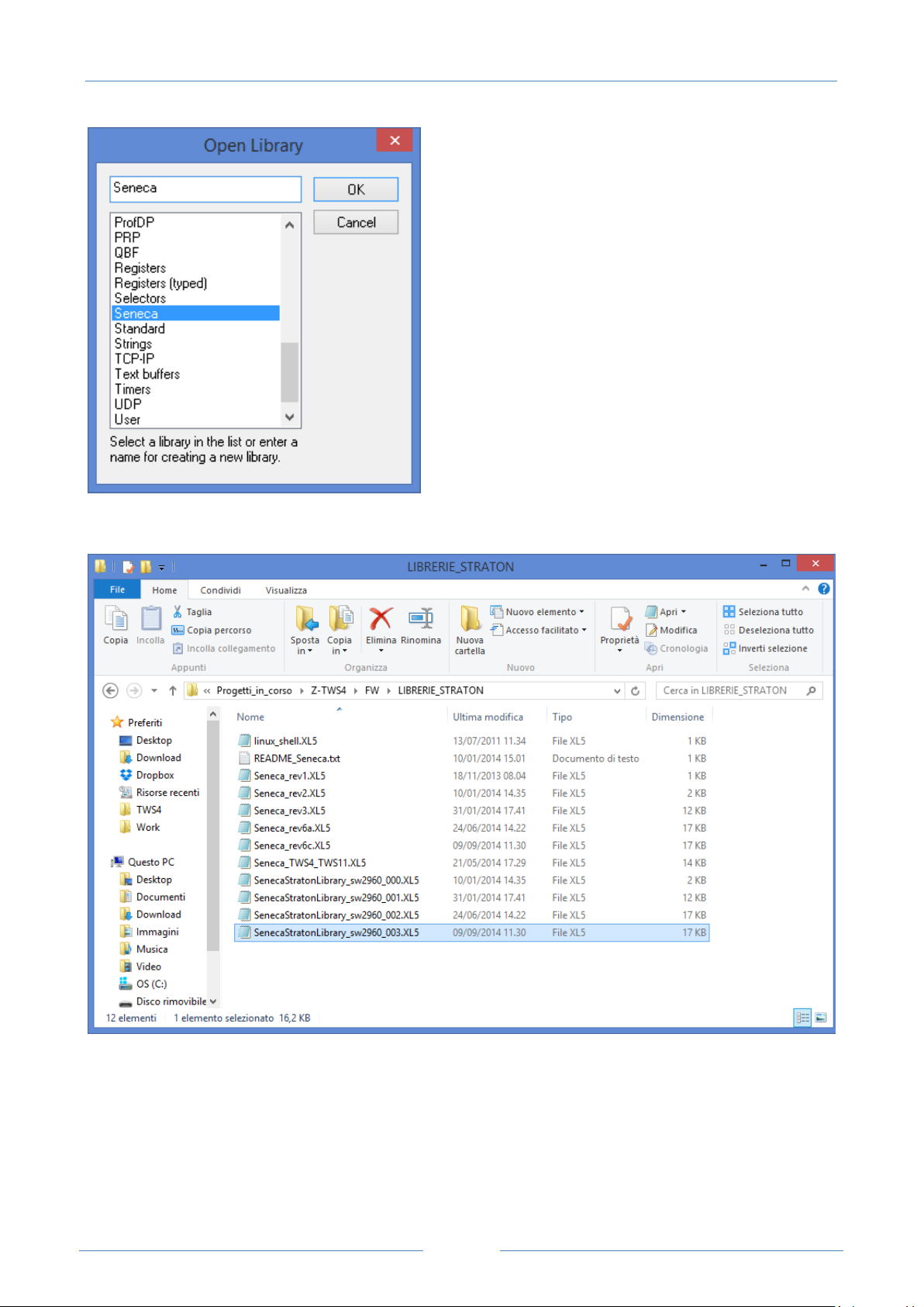
First, we must add the Seneca FB Library (file SenecaStratonLibrary.XL5) to the IDE, using the “Library
Manager” tool:
Select the “File / Open Library” option and enter the “Seneca” name to create the new Seneca library.
Page 35
USER MANUAL – Z-TWS4/Z-PASS2-S/S6001-RTU
35
Then, import the Library (menu “Tools / Import”):
Page 36
USER MANUAL – Z-TWS4/Z-PASS2-S/S6001-RTU
36
Save the library (menu “File / Save Library”).
The procedure to add the “Profiles library” to the IDE is identical to the one just explained; the only
difference is that the SenecaStratonProfiles.XL5 file shall be selected (instead of the
SenecaStratonLibrary.XL5 file).
Now that the “low-level” FBs are available, we have to install the UDFB library.
Page 37
USER MANUAL – Z-TWS4/Z-PASS2-S/S6001-RTU
37
The UDFB library is provided as a zip file, containing the following folders:
TWS_MISC
ZPASS2_Template
S6001_Template
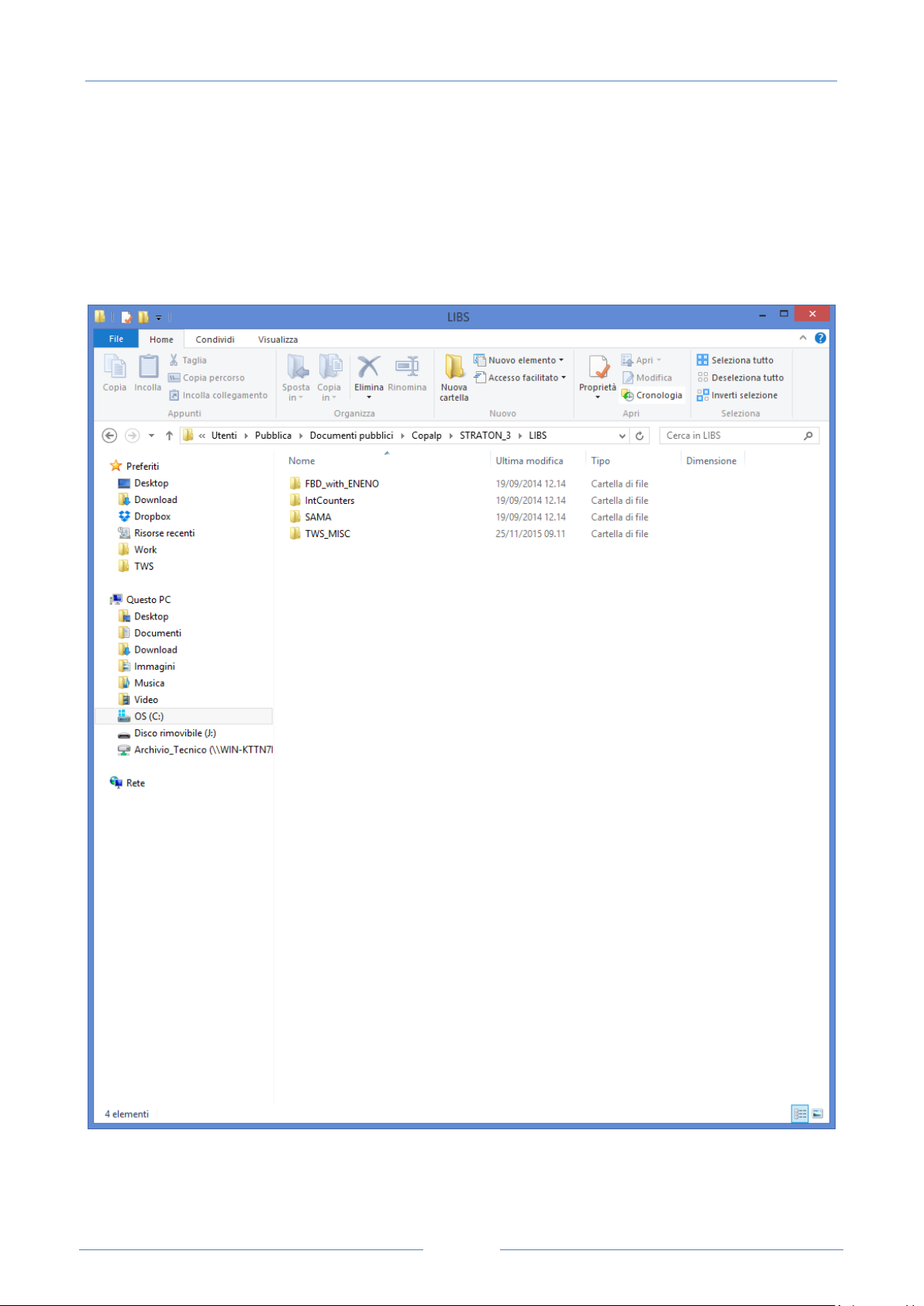
The TWS_MISC folder shall be copied into the following directory:
C:\Users\Public\Documents\Copalp\STRATON\LIBS
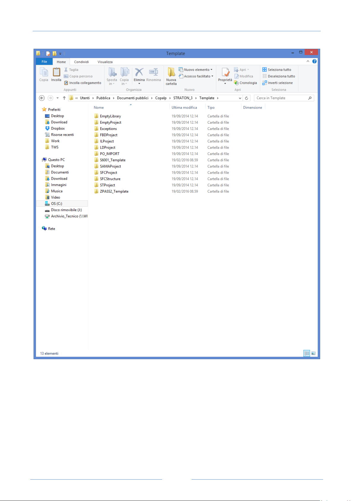
The ZPASS2_Template and S6001_Template folders shall be copied into the following directory:
C:\Users\Public\Documents\Copalp\STRATON\Template
Page 38
USER MANUAL – Z-TWS4/Z-PASS2-S/S6001-RTU
38
8.1.2 Creatin g a pr oject for Seneca CPUs
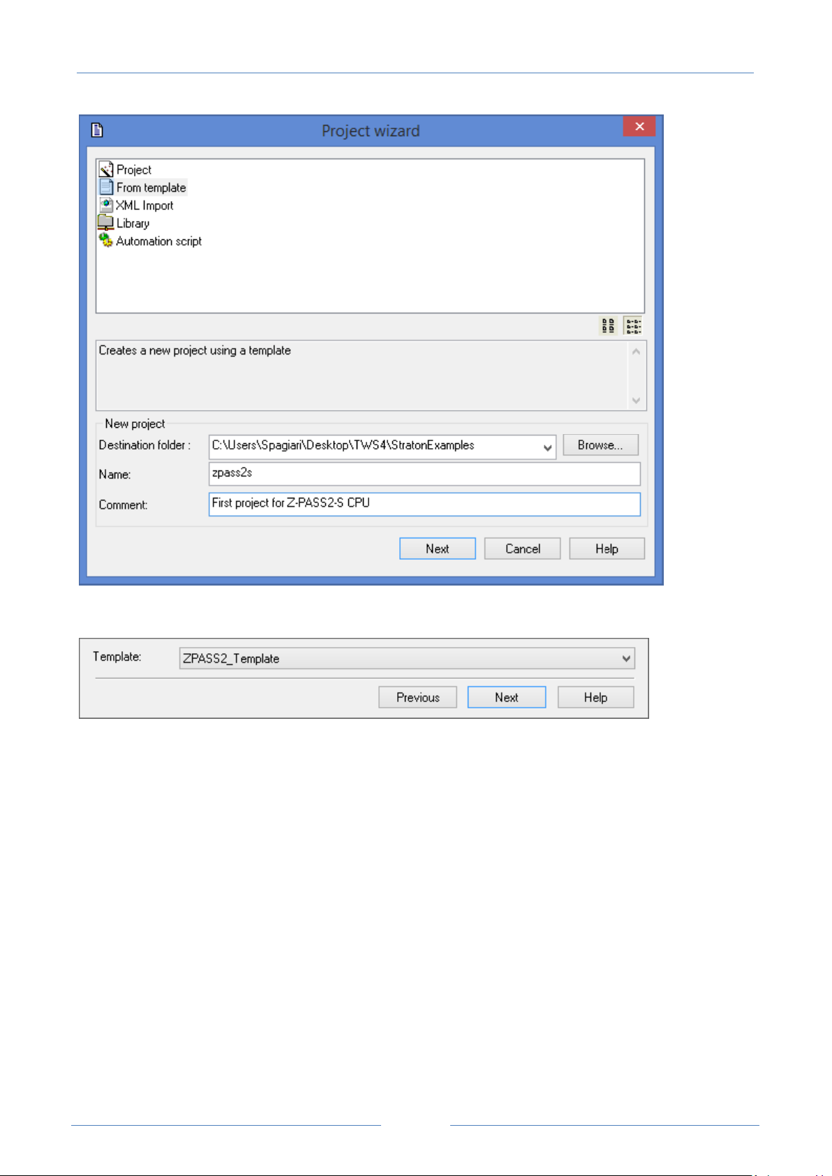
Run the StratON IDE and create a new project based on a template, as in the following figure:
Page 39
USER MANUAL – Z-TWS4/Z-PASS2-S/S6001-RTU
39
Select the “ZPASS2_Template” (or “S6001_Template”) in the template list.
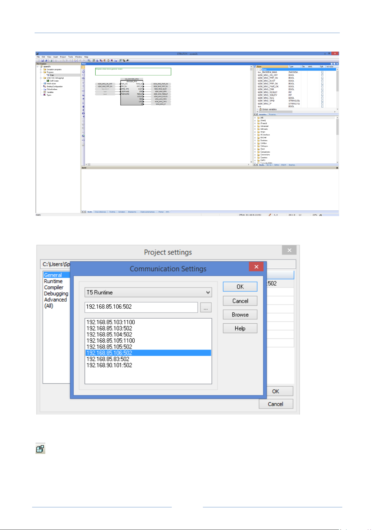
Now, as you can see in the following figure, in the Main program a ZMODEM_MNG UDFB instance is
already available, which lets you easily control the Z-PASS2-S/S6001-RTU modem.
Page 40
USER MANUAL – Z-TWS4/Z-PASS2-S/S6001-RTU
40
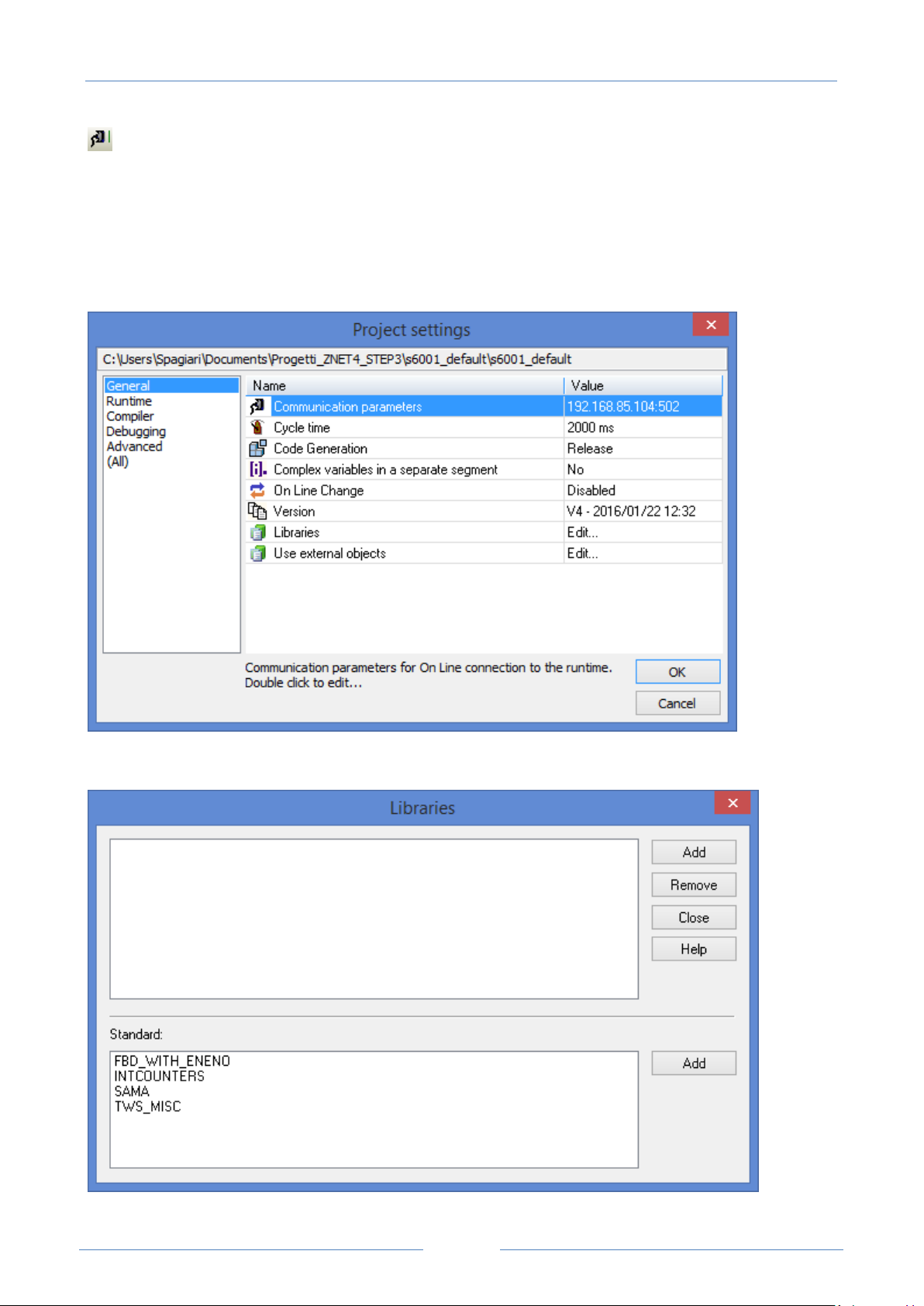
Set the correct target IP address (for example 192.168.85.106); normally, the port shall be set to 502:
Then press the icon:
to compile the project.
Download the code by pressing the icon:
Page 41
USER MANUAL – Z-TWS4/Z-PASS2-S/S6001-RTU
41
The project file will be placed into the /disk directory of the Device.
If the Straton project is not based on “ZPASS2_Template”/”S6001_Template”, the Seneca UDFB library can
still be used, as described in the following.
In the Straton IDE, go to the “Project Settings” window, shown below (menu “Project/Settings”):
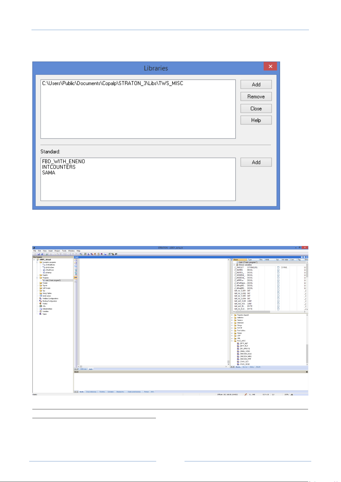
Click on “Libraries / Edit…”; the following window is shown:
Page 42
USER MANUAL – Z-TWS4/Z-PASS2-S/S6001-RTU
42
Select the “TWS_MISC” library and click on “Add”.
Finally, click on “Close”.
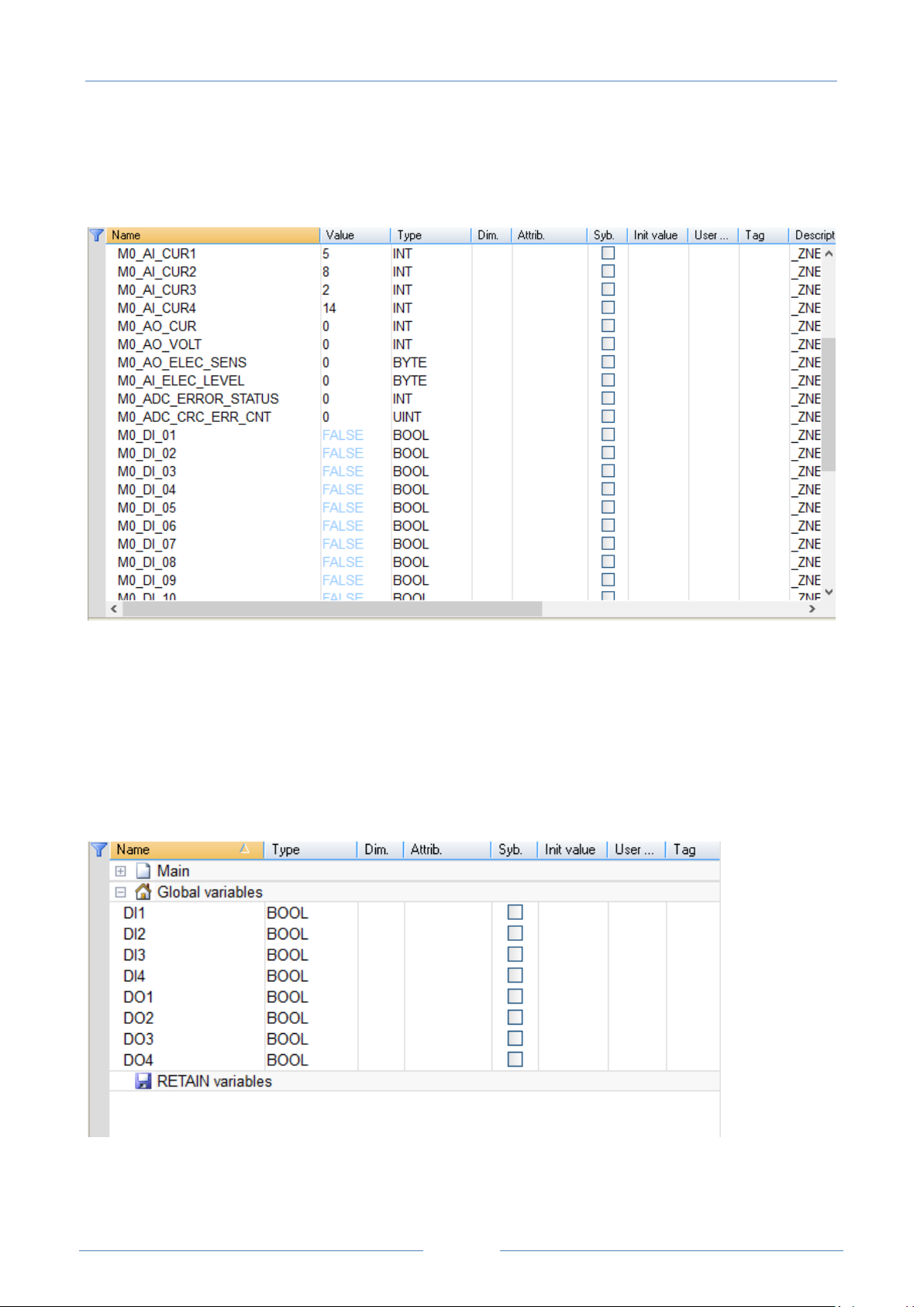
Now, the UDFB library is available in the project, as shown in the following figure:
If the Straton project has been built using the Seneca Z-NET4 SW (see chapter 20), the TWS_MISC is already
included, so the above procedure is not needed.
Page 43
USER MANUAL – Z-TWS4/Z-PASS2-S/S6001-RTU
43
In particular, when using S6001-RTU CPU, Z-NET4 SW provides a simple way to create the base Straton
project; in fact, all the variables corresponding to the CPU I/Os will be inserted in the project, as shown in
the following figure.
For more information about Straton IDE and related tools, please refer to StratON tutorials and on-line
help.
8.1.3 Z-PAS S 2-S-IO profiles
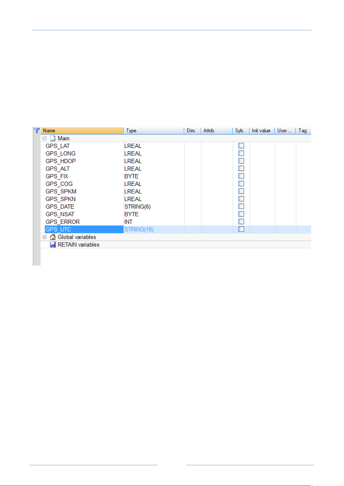
Two Straton I/O profiles are available for Z-PASS2-S-IO CPU.
The first profile, named “ZPASS_DIO”, provides variables corresponding to the available Digital I/Os, as
shown in the following figure.
It should be noted that four “DIx” variables and four “DOx” variables are declared, corresponding to the
maximum number of inputs and outputs possibly available; the Digital I/O configuration (see paragraph
Page 44
USER MANUAL – Z-TWS4/Z-PASS2-S/S6001-RTU
44
18.1.13) determines which of these variables are actually handled by the PLC; for example, if DIDO1 is set
as an input and DIDO2 as an output, DI3 and DO4 will be handled while DI4 and DO3 will not be used.
Moreover, while the variables corresponding to the inputs are updated by the PLC regardless of their
function modes, only the variables corresponding to the outputs set as “General Output” will actually affect
the digital outputs.
The second profile, named “ZPASS_GPS”, provides variables corresponding to the information given by the
GPS module, as shown in the following figure.
In particular, the GPS_ERROR variable tells if the other variables contain valid and updated values or not, in
the following way:
- GPS_ERROR = 0 GPS fixed; variables contain updated values
- GPS_ERROR = -1 GPS not fixed; variables contain not updated, possibly invalid, values
- GPS_ERROR = -2 some error has occurred; variables contain invalid values
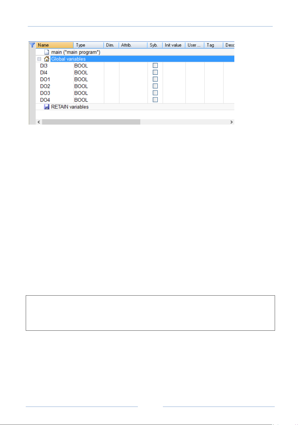
8.1.4 Z-TWS4-IO profile
The “ZPASS_DIO” profile is available also for Z-TWS4-IO, providing variables corresponding to the available
Digital I/Os, as shown in the following figure.
Page 45
USER MANUAL – Z-TWS4/Z-PASS2-S/S6001-RTU
45
It should be noted that two “DIx” variables and four “DOx” variables are declared, corresponding to the
maximum number of inputs and outputs possibly available; the Digital I/O configuration (see paragraph
18.1.13) determines which of these variables are actually handled by the PLC; for example, if DIDO1 is set
as an input and DIDO2 as an output, DI3 and DO4 will be handled while DI4 and DO3 will not be used.
Moreover, while the variables corresponding to the inputs are updated by the PLC regardless of their
function modes, only the variables corresponding to the outputs set as “General Output” will actually affect
the digital outputs.
8.2 Energy Management Protocols
The StratON soft-PLC installed on Z-TWS4/Z-PASS2-S/S6001-RTU supports the following “Energy
Management” protocols:
IEC 60870-5-101 (Master/Slave)
IEC 60870-5-104 (Master/Slave)
IEC 61850 (Master/Slave)
The activation of these protocols is license-based.
Please contact Seneca to get more information about getting the license for Energy Management protocols.
8.3 StratON Redundancy
WARNING!
At the date of this manual, the “StratON Redundancy” functionality is still in a “Beta version”; this means
that the proper operation of this functionality is not guaranteed for every kind of application; please contact
Seneca for further information.
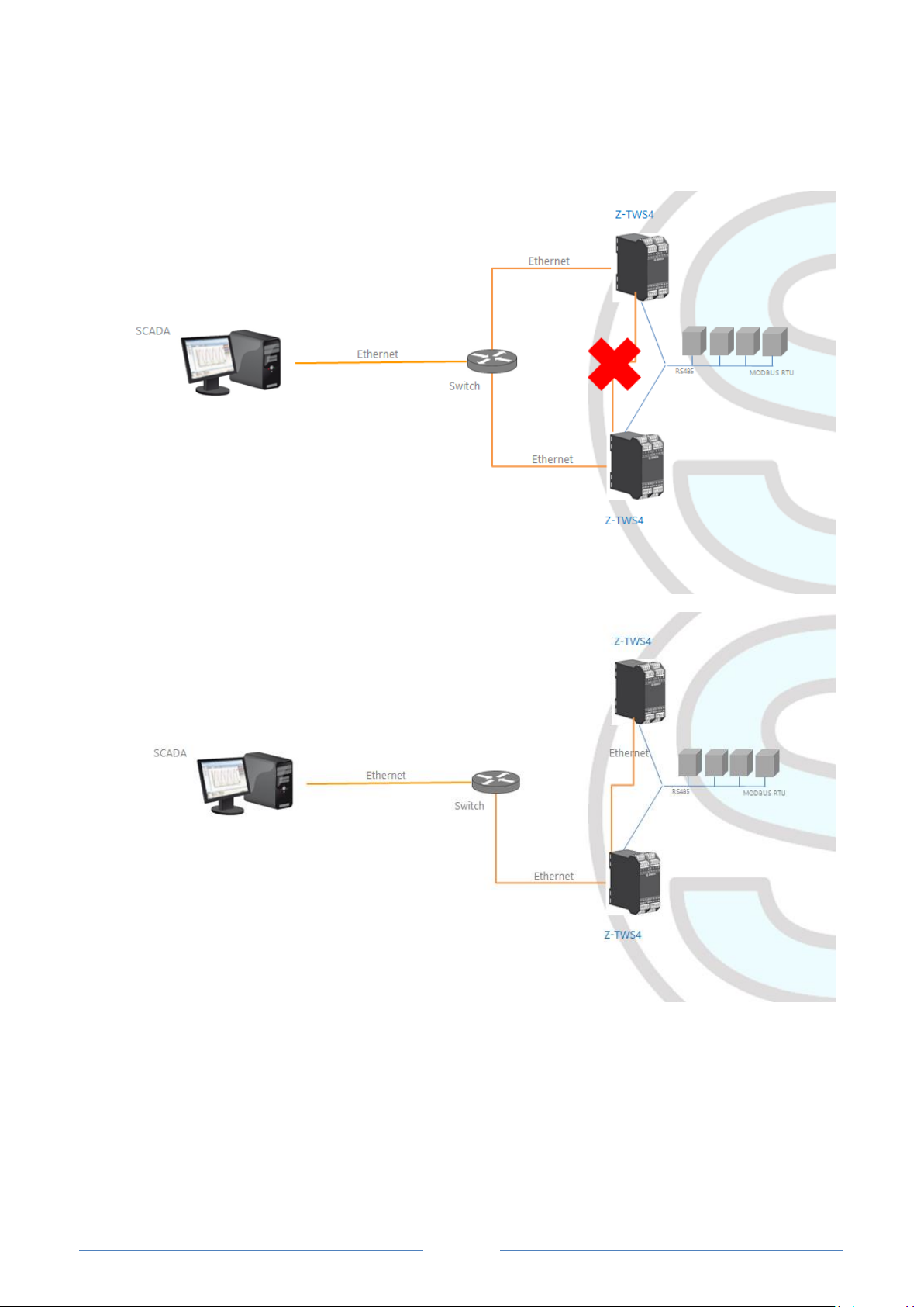
The StratON PLC provides a “Redundancy” functionality:
when this feature is enabled, two CPUs (Z-TWS4 or Z-PASS2-S or S6001-RTU) run the same StratON
application; the two CPUs connect each other via the Ethernet, in order to keep variables, state-machines
etc. synchronized between them; in each moment, only one of the two CPUs actually runs the application
and drives the fieldbus; if, for any reason, that CPU stops running, the application execution is handed over
to the second CPU.
Page 46
USER MANUAL – Z-TWS4/Z-PASS2-S/S6001-RTU
46
When the redundancy is used, some care must be taken when connecting the devices, in order to avoid
Ethernet loops; the Ethernet connections shall be set up as shown in the following figures.
Please see paragraph 18.1.2 for a description of the configuration parameters related to StratON
Redundancy.
9 Ethernet Mode (Z-PASS2-S-R01/Z-PASS2-S-IO/Z-TWS4-IO)
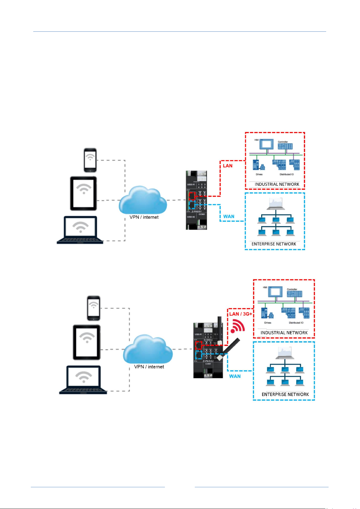
In Z-PASS2-S-R01/Z-PASS2-S-IO/Z-TWS4-IO products, the two available Ethernet ports can be configured as
two fully separated network interfaces (“LAN” and “WAN”) or, as in the older versions, they can work as
Page 47
USER MANUAL – Z-TWS4/Z-PASS2-S/S6001-RTU
47
ports of an Ethernet switch; the user can choose between the “LAN/WAN” mode and the “Switch” mode,
by means of a configuration parameter (“Ethernet Mode”) (see paragraph 18.1.2).
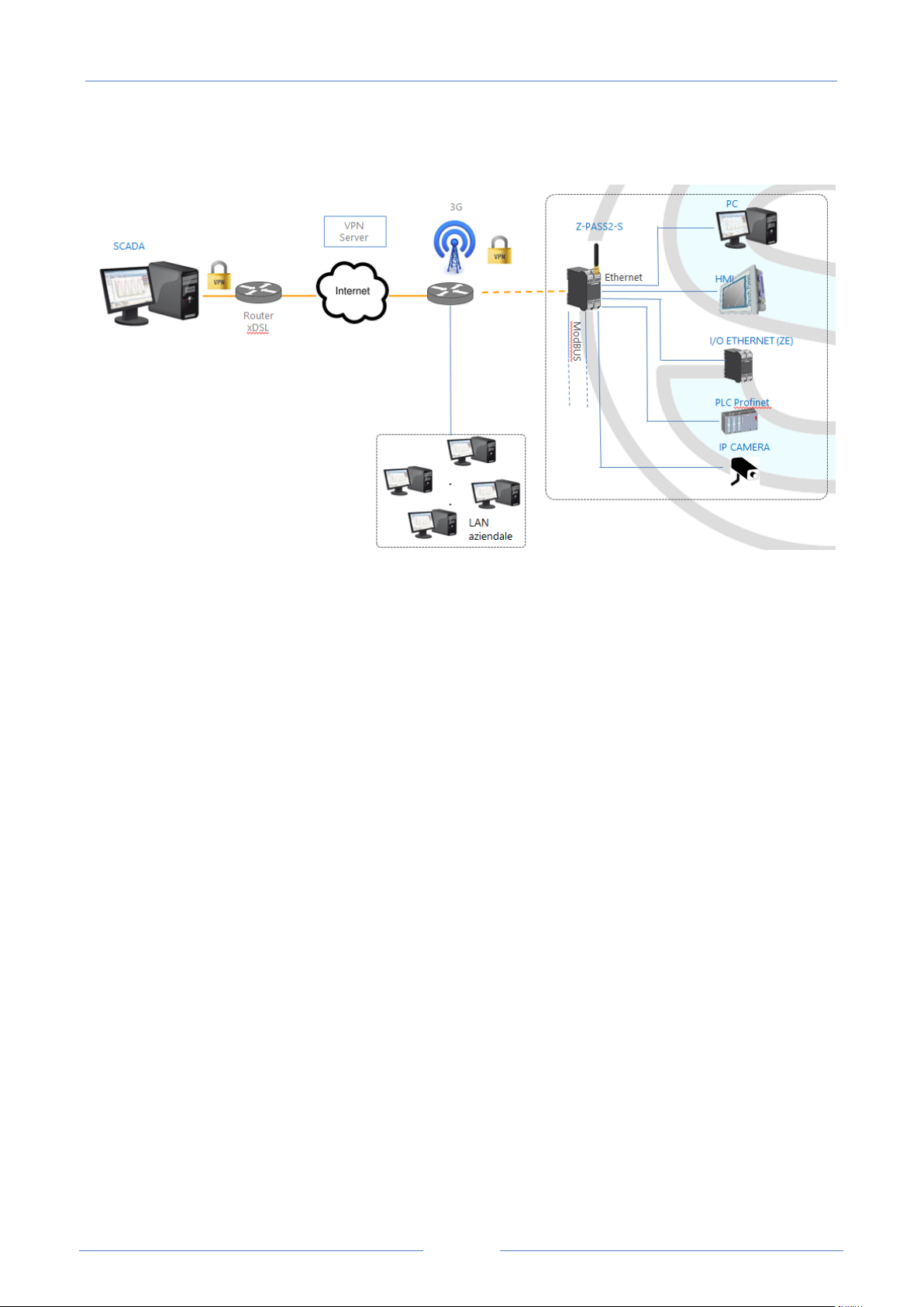
The “LAN/WAN” mode is needed when the “industrial” network connected to the LAN interface
(comprising e.g. HMI and PLC devices) shall be separated from the “enterprise” network connected to the
WAN interface (comprising enterprise PCs and servers); when the Device is remotely accessed through the
WAN interface, only devices connected to the LAN interface can be reached, while access to machines lying
in the enterprise network is forbidden; this is depicted in the following two figures.
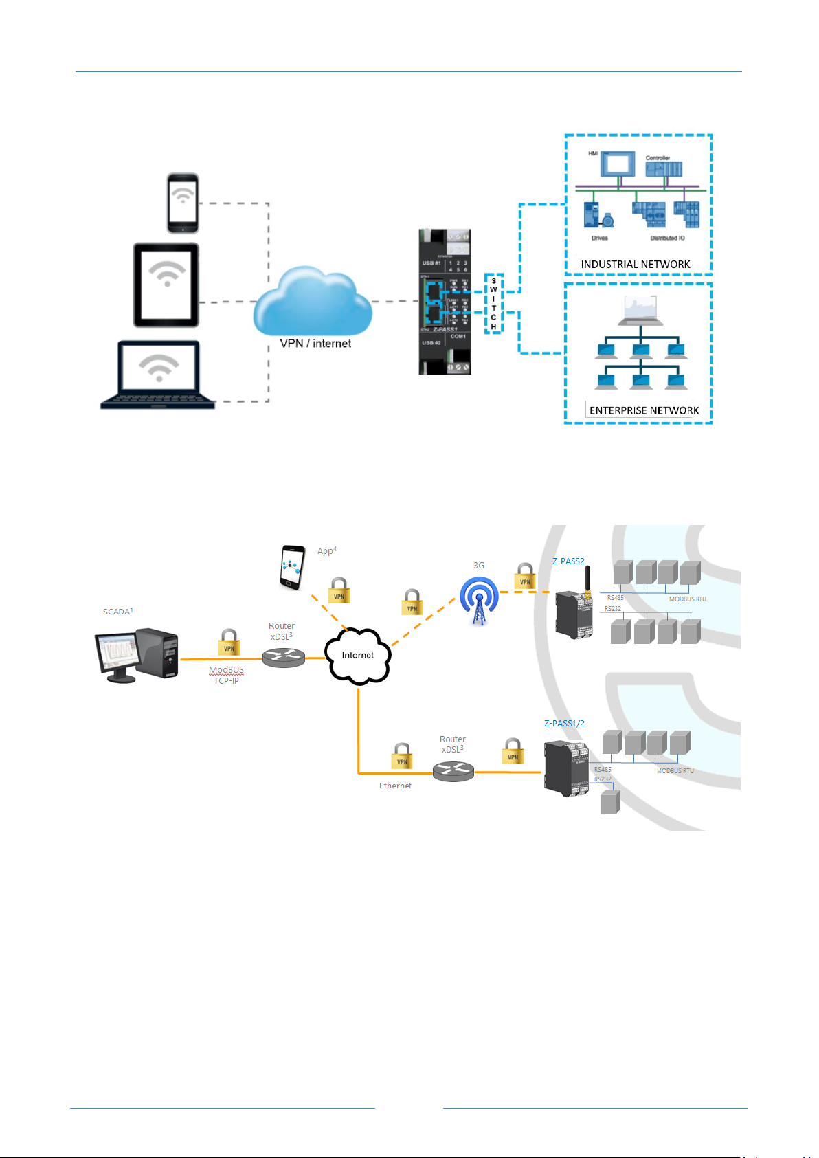
When this separation is not needed or when the Internet access is achieved only through the mobile (3G+)
interface, the “Switch” mode still lets the Device be used as an Ethernet switch, as shown in the following
figure.
Page 48
USER MANUAL – Z-TWS4/Z-PASS2-S/S6001-RTU
48
10 VPN
Z-TWS4/Z-PASS2-S/S6001-RTU support the standard OpenVPN protocol.
The main advantages that come from using a VPN are:
secure connections, since transported data are encrypted;
the ability to establish connections without interfering with the corporate LAN;
no need to have a static/public IP address on the WAN side;
remote configurability by a built-in Web Server.
Two “VPN modes“ are available, named “OpenVPN” and “VPN Box”, respectively.
Page 49

USER MANUAL – Z-TWS4/Z-PASS2-S/S6001-RTU
49
The “OpenVPN” mode can be used when the Device shall be installed in an already existing VPN. In this
case, an OpenVPN server shall be available and the certificate and key files for the Device client shall be
provided by the VPN administrator; the files can be uploaded to the Device using the “VPN configuration”
page of Device Web Server.
If the VPN infrastructure does not exist yet, the advisable choice is to adopt the “VPN Box” solution,
developed by Seneca. The “VPN Box” is an hardware appliance (or a virtual machine) which lets the user
easily setup two alternative kinds of VPN:
- “Single LAN” VPN
- “Point-to-Point” VPN
In the “Single LAN” VPN, all devices and PCs (and associated local subnets) configured into VPN are always
connected in the same network. In this scenario any PC Client can connect to any Device and to other
machines which lie in the Device LAN, but also any device/machine can connect to any other remote
device/machine which belongs to the same VPN network. This VPN architecture puts some constraints on
the device sub-networks definition, in fact all VPN clients must have a different IP address and different
local LAN, to avoid conflicts. The software named “VPN BOX Manager” configures VPN BOX and will help
you to avoid errors defining local subnets.
In the “Point-to-Point” VPN, a client PC, in a given moment, can perform a single connection, on demand,
to only one Device (and to machines which lie in the Device LAN) at time. Furthermore, devices can’t
communicate each other. The advantage of this architecture is that the same sub-network can be used in
all sites. Point to point mode makes it possible to define user groups and manage them. This VPN modality
must be configured on “VPN Box”.
There are two kinds of “Point-to-Point” VPN:
routing Layer 3 VPN
bridging Layer 2 VPN
In “Routing Layer 3 VPN”, only IP (Layer 3) packets are transported over the VPN tunnel and a new virtual
LAN is created with a network subnet which must be different from the LAN subnets of the server and
clients.
Conversely, in “Bridging Layer 2 VPN”, all Ethernet frames are transported over the VPN tunnel and the
clients are inserted in the server LAN.
Each of the two kinds has benefits and drawbacks:
Layer 2 benefits/drawbacks:
can transport any network protocol
broadcast traffic (e.g.: DHCP) is transported
causes much more traffic overhead on the VPN tunnel
Layer 3 benefits/drawbacks:
can transport only IP traffic
broadcast traffic (e.g.: DHCP) is not transported
lower traffic overhead, transports only traffic which is destined for the VPN clients
The “VPN Box” is supplied with two Windows applications:
Page 50
USER MANUAL – Z-TWS4/Z-PASS2-S/S6001-RTU
50
4
4
5
the “VPN Box Manager”, which allows to configure the VPN
mode on the VPN Box and manage the
devices5
the “VPN Client Communicator”, which lets the user connect the PC to the network (in the “Single
LAN” case) or to a specific device (in the “Point-to-Point” case)
A detailed description of “VPN Box” can be found in the “VPN Box User Manual”.
A detailed description of Z-TWS4/Z-PASS2-S/S6001-RTU VPN configuration parameters is given in 18.1.4
paragraph.
The following two sub-paragraphs give some more info about the two kinds of VPN.
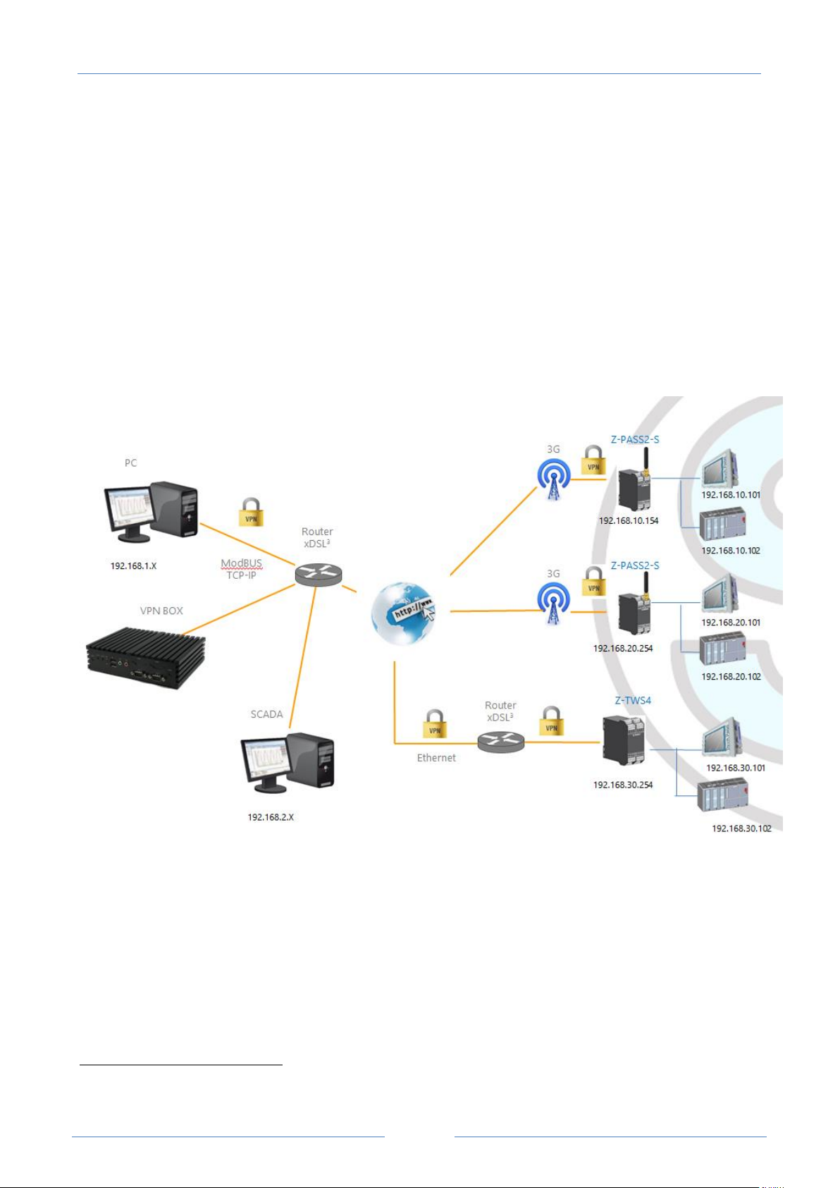
10.1 “Single LAN” VPN
The above figure gives an example of a “Single LAN” VPN.
The client PC (with IP address 192.168.1.X) can connect, just as an example, to the first Z-PASS2-S by using
its 192.168.10.154 IP address and to the PLC in the Z-PASS2-S LAN by using its local IP address
192.168.10.102.
Also, two devices which lie in two different LANs of the same VPN network (e.g.: 192.168.10.101 and
192.168.20.102) can connect to each other, again using their local IP addresses.
Only one of the two kinds of VPN can be configured on a given VPN Box.
“VPN Box” functionality is available also on Seneca Z-PASS1 and Z-PASS2 products.
Page 51
USER MANUAL – Z-TWS4/Z-PASS2-S/S6001-RTU
51
To let this scenario work correctly, an essential rule must always be followed: the Device LANs and the PC
LAN shall have different and not colliding subnets; so, in the above figure, the following subnets allocation
has been depicted:
PC LAN 192.168.1.0/24
SCADA LAN 192.168.2.0/24
Z-PASS2 LAN 192.168.10.0/24
Z-PASS2 LAN 192.168.20.0/24
Z-PASS1 LAN 192.168.30.0/24
The “VPN Box Manager” application guides you in the configuration task, checking that no subnet/IP
address conflict is present in the network.
If subnet/conflicts cannot be avoided, using a “Single LAN” VPN is still possible if local IP addresses are not
used; devices can be reached by means of their VPN IP addresses and machines beyond them can be
reached by configuring some “port forwarding” rules on the Device Router (see 18.1.5 paragraph).
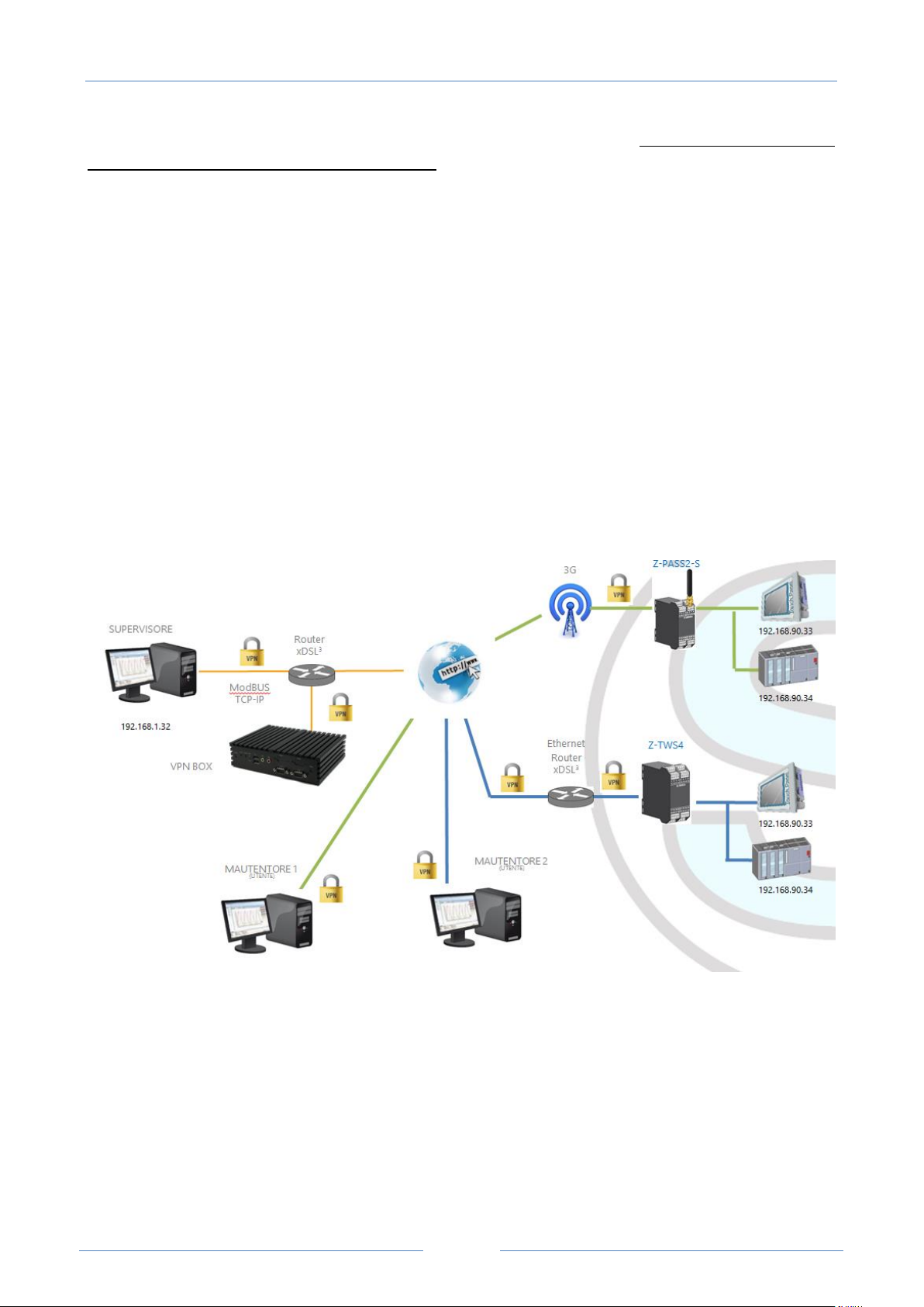
10.2 “Point-to-Point” VPN
The above figure gives an example of a “Point-to-Point” VPN.
In this scenario a PC (acting as a VPN Client) can connect, on demand, to only one Device and its subnet,
using local IP addresses. Since the client “sees” just one Z-TWS4/Z-PASS2-S/S6001-RTU (and attached
devices) at time, the same subnet configuration can be assigned to different sites, without creating
conflicts.
For this kind of VPN, the “VPN Box Manager” application lets define group of users that can connect only
to assigned devices.
Page 52
USER MANUAL – Z-TWS4/Z-PASS2-S/S6001-RTU
52
The “VPN Client Communicator” application retrieves the list of devices which are available for the logged
user; then the user can select one device on the list and connect to it.
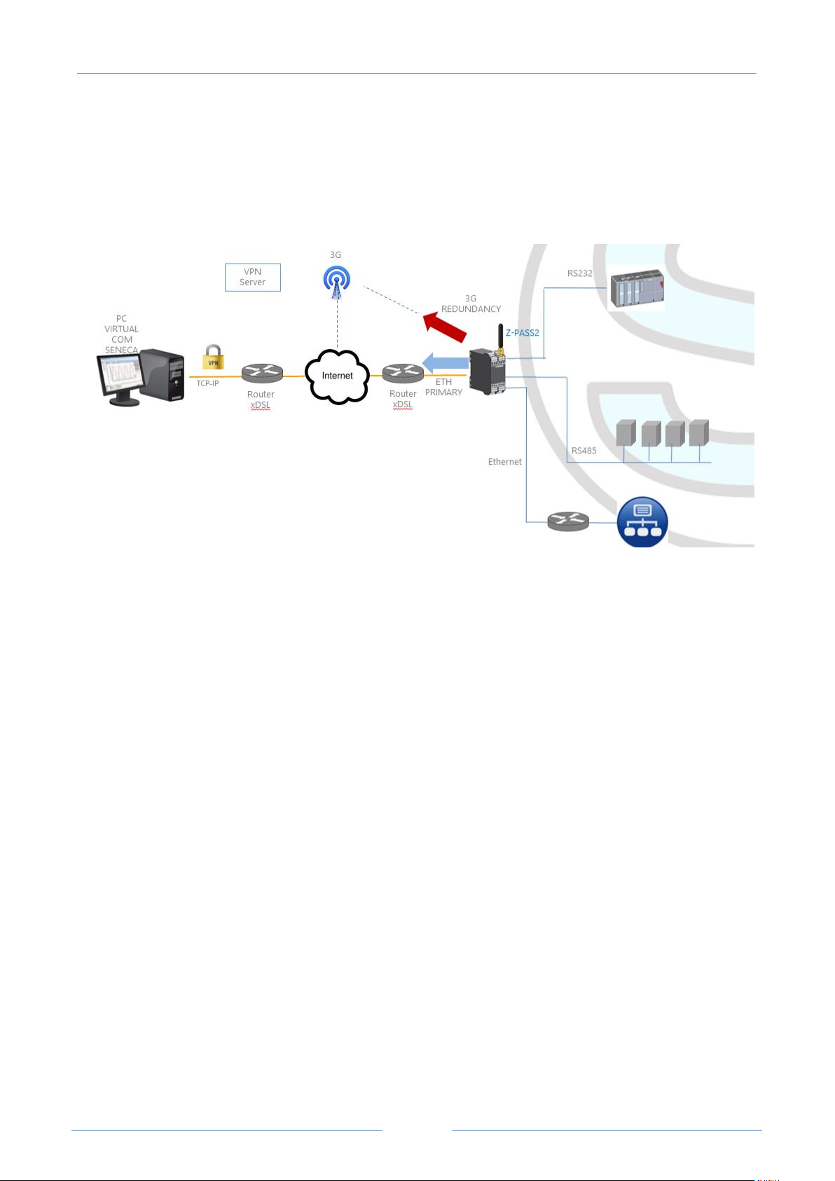
11 Network Redundancy
“Network Redundancy” is a functionality than can be enabled on the Device when a 3G modem is available
(true for Z-PASS2-S and S6001-RTU).
This functionality switches the network interface used to access the Internet from the Ethernet (“primary”
interface) to the Mobile/3G (“secondary” interface), when Internet access through the primary interface
becomes unavailable; when access through the primary interface become available again, the network
interface is switched back to Ethernet.
The parameters provided to configure Network Redundancy are explained in paragraph 18.1.2 “Network
and Services”.
Page 53
53
12 Router
USER MANUAL – Z-TWS4/Z-PASS2-S/S6001-RTU
As already told before, “Router” functionality routes packets between the WAN (Mobile Network) interface
and the LAN (Ethernet) interface and vice versa; so, this functionality especially makes sense when a 3G
connection is active, which needs the availability of a 3G modem (true for Z-PASS2-S and S6001-RTU).
More specifically, an important feature of the Router is what is known as “IP forwarding”; this means that
when the Device receives a packet not targeted for it, it does not discard the packet but forwards it to its
actual destination; when a packet is routed from the LAN to the WAN, the Device also performs what is
known as “IP masquerading”, meaning that the original source IP address is replaced with the IP address of
the WAN (Mobile Network) interface.
Another important feature is the availability of a DNS server/forwarder, which can resolve names either by
itself or querying the external configured DNS server.
Also, a DHCP server is available which assigns IP addresses to clients connected on the Device LAN; here,
you can configure the range of addresses used by the server and the lease time.
There is also the possibility to define up to five “Port Forwarding” rules or “Virtual Servers”; using these
rules, you can, for example, redirect packets received on a TCP or UDP port to another Device port or to
another machine, with a different IP address, on the same or another port.
As an alternative to using “Port Forwarding” rules, Router + VPN functionalities allow the use of local
addresses, as shown in the previous chapter; in the router configuration, a flag is given to enable this
feature.
A detailed description of the Router configuration can be found in paragraph 18.1.5.
Page 54

USER MANUAL – Z-TWS4/Z-PASS2-S/S6001-RTU
54
6
7
13 Remote Connection Disable
Z-PASS2-S-IO and Z-TWS4-IO products provide a dedicated digital input and a dedicated digital output to
control and monitor remote connection to the device.
In details:
- when “Remote Connection Disable” digital input is set to HIGH state, remote connection to the
device is disabled; conversely, when “Remote Connection Disable” digital input is set to LOW state,
remote connection to the device is enabled; “Remote Connection Disable” digital input state is
reported by the “RCD” LED;
- “Remote Connection Active” digital output is set to HIGH state when the device is remotely
accessed (VPN connection is active); it is set to LOW state when VPN connection is not active.
Four levels of security can be configured to disable remote connection:
- Level 1 (“VPN Connection”): VPN connections are disabled in any VPN mode (VPN Box Point-to-
Point, VPN Box Single LAN, OpenVPN), but VPN Box Service is still running, so the device can still be
monitored on VPN Box Manager;
- Level 2 (“VPN Service”): VPN Box Service is disabled, but the device can still access the Internet and
send/receive SMSs;
- Level 3 (“Internet Connection”): any Internet access is disabled, but the device can still
send/receive SMSs;
- Level 4 (“SMS Service”): modem is off, so SMSs can’t be sent/received.
See “Digital I/O Configuration” paragraph to learn how to set the desired security level.
14 Auto-APN
The Auto-APN feature lets the Device establish mobile data connections without requiring the user to
configure APN data6 for the SIM in use.
This is accomplished by using the SIM IMSI and, possibly, some other data available on the SIM, to select
the proper APN record in an internal DB7, containing APN records for all mobile operators in the world.
In some particular cases, however, when a “custom APN” shall be used, the Auto-APN feature can be
disabled, setting the “APN Mode” parameter to “Manual”, in the “Mobile Network” page (see paragraph
18.1.10).
15 M-Bus (ONLY Z-TWS4-IO and Z-PASS2-S-IO)
Z-TWS4-IO and Z-PASS2-S-IO, can be connected to a M-Bus fieldbus in the following way:
- connecting the Seneca “Z-MBUS” RS232-MBUS adapter to the COM1 serial port;
- setting the COM1 mode to RS232 (see paragraph 18.1.2).
APN data are: APN, Username, Password and Authentication Type.
This DB is updated to the one used in the last Android O.S. version.
Page 55

USER MANUAL – Z-TWS4/Z-PASS2-S/S6001-RTU
55
To handle M-Bus devices, the following resources are provided:
- the “M-Bus” section web pages
- the MBUS_READ_CTL function
- the MBUS_WRITE_RAW function block
The M-BUS web pages lets you scan the bus, searching for devices, detecting either their primary addresses
or secondary addresses; it also lets you read the data records and slave information from a device and
create the configuration files to be imported in Straton PLC.
The MBUS_READ_CTL FB lets you start/stop the M-BUS acquisition;
the MBUS_WRITE_RAW FB lets you build and send a generic M-Bus frame, thus providing a flexible way to
send configuration commands to M-Bus devices.
16 OPC Unified Architecture (OPC UA) protocol
OPC Unified Architecture (OPC UA) is a standardized machine to machine communication
protocol for industrial 4.0 automation developed by the OPC Foundation.
OPC UA is a vendor-independent communication protocol and it’s based on the client-server principle.
The devices support both OPC-UA server and OPC-UA client protocols (up to 10 servers by using the OPCUA client Function Blocks).
17 Upgrading the firmware by USB pen
The Device firmware can be upgraded by means of a USB pen; a pen drive formatted with FAT32 filesystem is needed.
The procedure is the following:
1) download the FW file from one of the following links:
http://www.seneca.it/products/z-tws4
http://www.seneca.it/products/z-pass2-s
http://www.seneca.it/products/s6001-rtu
the downloaded file is a .zip file; extract the FW file from it;
the FW file shall have a name like the following:
SW002940_xxx.bin
2) copy the file into the root of the USB pen
3) switch off the Device
4) insert the USB pen into the USB#1 port
Page 56

USER MANUAL – Z-TWS4/Z-PASS2-S/S6001-RTU
56
9
8
9
10
5) switch on the Device; the upgrade procedure will take some minutes to be completed; during this
time, the Device MUST NOT be switched off; during the procedure, the Device will be rebooted
several times; also, during the procedure, several LEDS will blink simultaneously8
6) the upgrade procedure is ended when only the LED “RUN” is blinking
7) remove the USB pen
18 Web Configuration Pages
NOTE: in this chapter, the web pages screen-shots are shown for only one of the products (Z-TWS4, ZPASS2-S, Z-PASS2-S-R01, Z-PASS2-S-IO, S6001-RTU); the pages for the other products are identical, except
for the product name shown in the top of the pages and for some details explained in the following
paragraphs.
Furthermore, for S6001-RTU one more page (“I/O View”) is available.
18.1 Administrator pages
The Device can be fully configured by means of a set of web configuration pages.
To access the Device configuration site, you have to connect the browser to the Device IP address on port
8080, e.g.:
http://192.168.90.101:808010
and, when asked, provide the following credentials (default values):
Username: admin
Password: admin
You come to the “Main View” page, described in the following paragraph.
This applies only to products with HW revisions IO and R01; in details: for IO HW revision, all LEDs will blink
simultaneously, except for Power, LAN/WAN, COM and modem LEDs; for R01 HW revision, RUN, VPN and SERV LEDs
will blink.
Also SERV and VPN LEDs might blink, depending on the Device configuration and status.
The default 80 HTTP port has been left available for customer pages.
Page 57
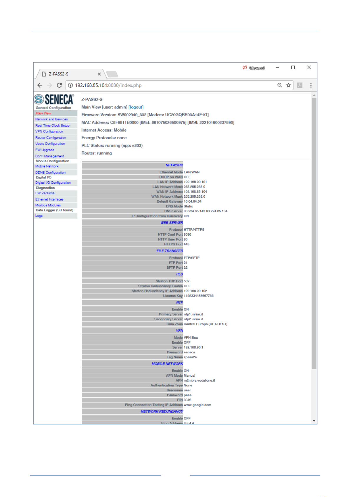
57
18.1.1 Ma i n Vi e w
USER MANUAL – Z-TWS4/Z-PASS2-S/S6001-RTU
In this page, main Device configuration parameters are shown, with their current values.
Page 58

USER MANUAL – Z-TWS4/Z-PASS2-S/S6001-RTU
58
On the left side of the page, like in all the other pages, a menu is shown which lets you access all the
configuration pages; the menu is divided in several sections:
General Configuration
Mobile Configuration (not available on Z-TWS4 and Z-TWS4-IO)
Digital I/O (on Z-PASS2-S-IO, Z-TWS4-IO products)
Diagnostics
Data Logger
In S6001-RTU, a “S6001-RTU” section is also present.
On top of the page, like in all the other pages, the following information are shown:
the page name
the FW version, along with the modem FW revision, for Z-PASS2-S/S6001-RTU; for S6001-RTU, the
FW version of the I/O board is also shown
the MAC address; the modem IMEI, for Z-PASS2-S/S6001-RTU; the SIM IMSI, for Z-PASS2-S/S6001-
RTU, when a SIM is present
the network interface used for Internet Access (i.e.: “Ethernet” or “Mobile”)
which energy protocols are enabled (on a license base)
the Soft PLC status (i.e.: “running” or “stopped”); if the PLC application execution is stopped or no
application is loaded on the Device, the status “app not running” is also shown; if the PLC
application is running, the name of the application is also shown
the Router status (i.e.: “running” or “disabled”)
The currently logged user (e.g.: “admin”) and the “Logout” link are also present, near the page name.
In this page, the following buttons are available:
“RESTART”, to perform the Device reboot
“FACTORY DEFAULT”, to reset the Device to its factory state
“CLEAN INTERNAL DATA LOGS”, to delete internal data log files (this does not affect the data log
files stored on the SD card, see paragraph 18.1.18)
Probably, the first parameters you need to change when setting up a new Device are those related to its
network configuration.
You can accomplish this in the “Network and Services” page, described in the following paragraph.
18.1.2 Ne tw o rk an d S ervic es
The parameters shown in this page slightly change, depending on the HW version of the product (ZTWS4/Z-PASS2-S or Z-PASS2-S-R01 or Z-TWS4-IO/Z-PASS2-S-IO) and, for new HW versions, on the selected
“Ethernet Mode”; this is shown in the following figures.
Page 59
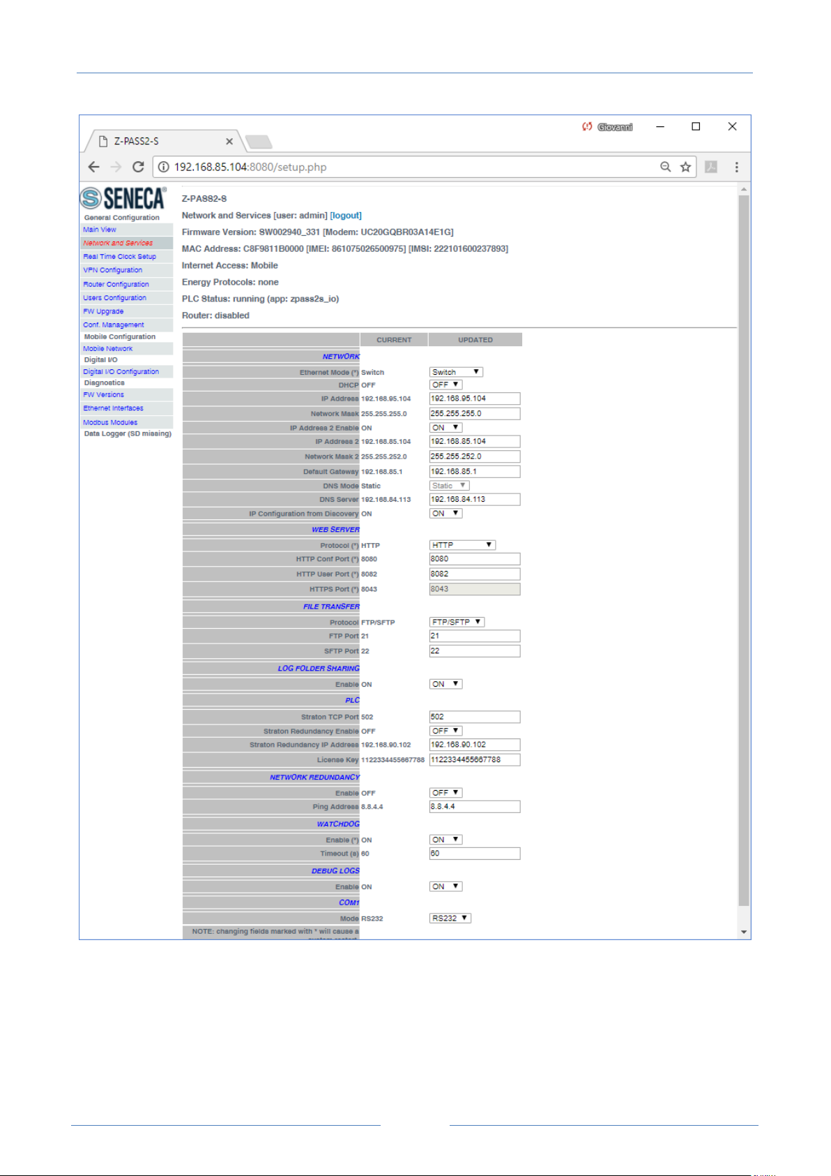
USER MANUAL – Z-TWS4/Z-PASS2-S/S6001-RTU
59
The previous figure shows the “Network and Services” page for a Z-PASS2-S-IO, when the “Ethernet Mode”
parameter is set to “Switch” ; it also applies to a Z-TWS4-IO in “Switch” mode.
Page 60
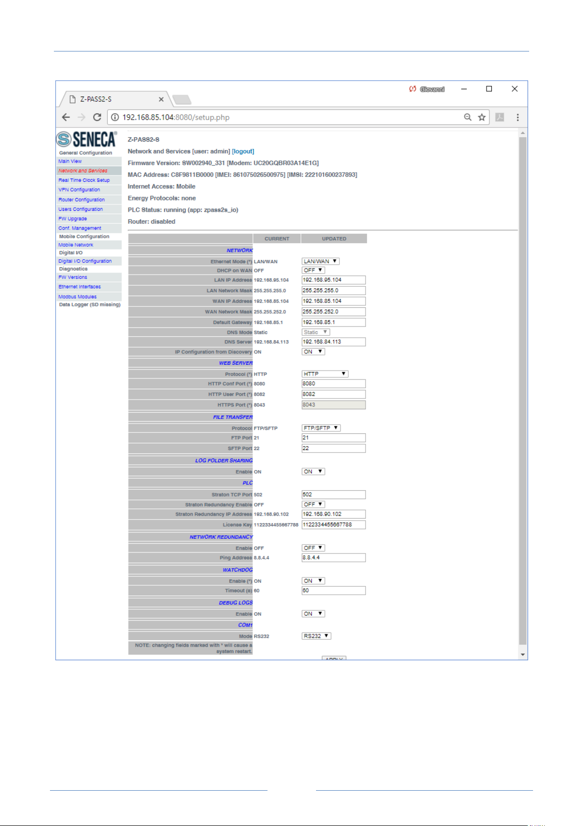
USER MANUAL – Z-TWS4/Z-PASS2-S/S6001-RTU
60
The previous figure shows the “Network and Services” page for a Z-PASS2-S-IO, when the “Ethernet Mode”
parameter is set to “LAN/WAN” it also applies to a Z-TWS4-IO in “LAN/WAN” mode.
Page 61
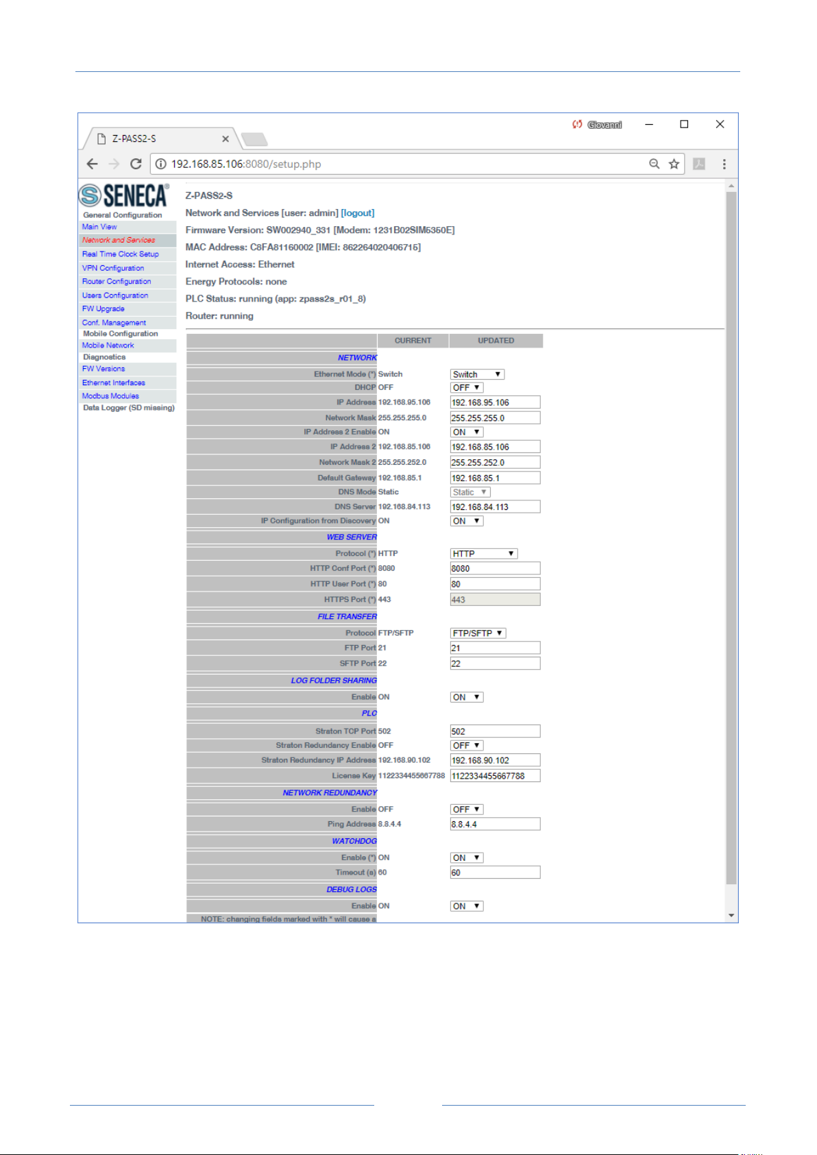
USER MANUAL – Z-TWS4/Z-PASS2-S/S6001-RTU
61
The previous figure shows the “Network and Services” page for a Z-PASS2-S-R01, when the “Ethernet
Mode” parameter is set to “Switch”.
Page 62
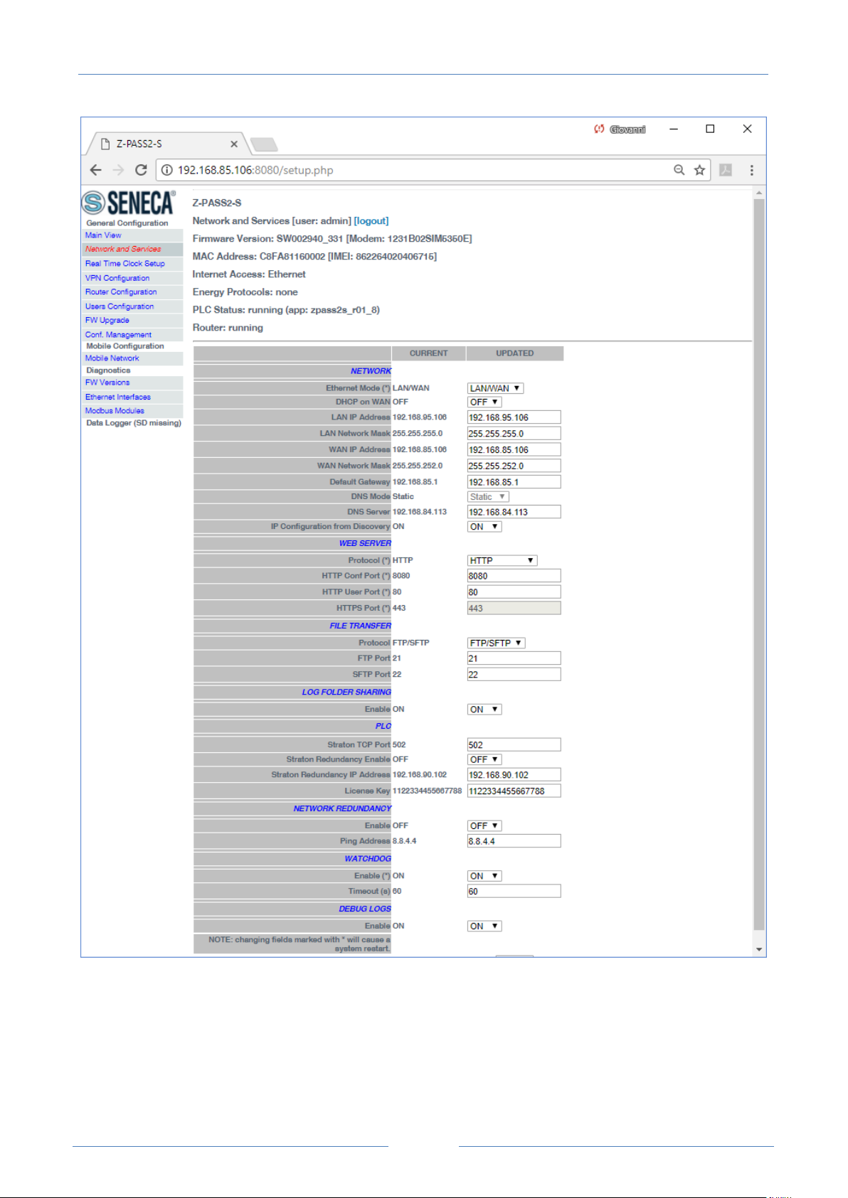
USER MANUAL – Z-TWS4/Z-PASS2-S/S6001-RTU
62
The previous figure shows the “Network and Services” page for a Z-PASS2-S-R01, when the “Ethernet
Mode” parameter is set to “LAN/WAN”.
Page 63
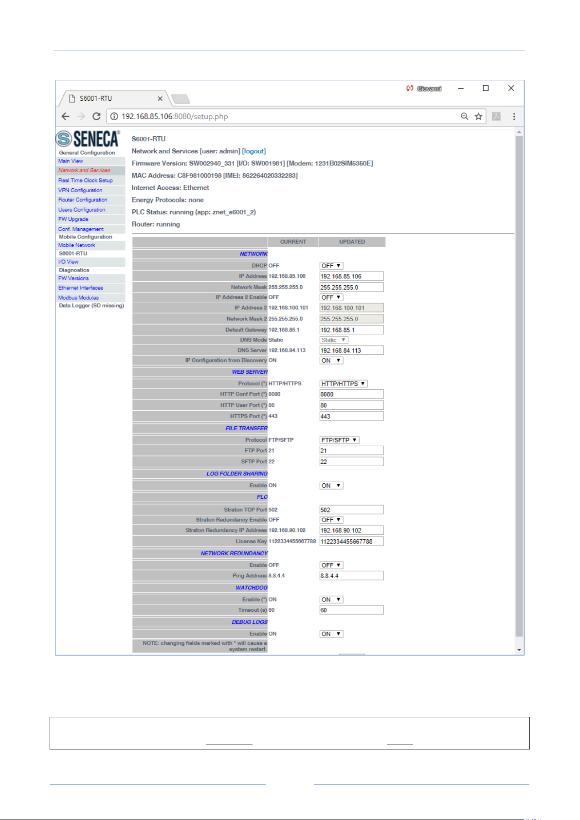
USER MANUAL – Z-TWS4/Z-PASS2-S/S6001-RTU
63
The previous figure shows the “Network and Services” page for a S6001-RTU; it also applies to a Z-TWS4
and Z-PASS2-S (old version).
There is an important difference between the parameter values shown in this page and those shown in the
“Main View” page: the former are configured values, whereas the latter are actual values.
Page 64

USER MANUAL – Z-TWS4/Z-PASS2-S/S6001-RTU
64
Field
Meaning
Default value
NETWORK/Ethernet Mode
This parameter determines if the
two Ethernet ports work as two
fully separated network interfaces
(“LAN/WAN”) or as the ports of an
Ethernet switch (“Switch”);
depending on the value of this
parameter, some other network
parameters are hidden/shown or
renamed as described below.
This parameter is available only for
Z-PASS2-S-R01, Z-PASS2-S-IO and
Z-TWS4-IO products. For all other
products, only “Switch” mode is
available, hence the parameter is
not shown.
LAN/WAN
Ethernet Mode = “Switch”
NETWORK/DHCP
Flag to enable/disable the DHCP
functionality on the Ethernet
interface.
OFF
NETWORK/IP Address
IP address of the Ethernet interface
(disabled when “DHCP” is set to
“ON”)
192.168.90.101
NETWORK/Network Mask
Network mask of the Ethernet
interface (disabled when “DHCP” is
set to “ON”)
255.255.255.0
NETWORK/IP Address 2 Enable
Flag to enable/disable the second
IP address on the Ethernet
interface.
Note that the second IP address
can be enabled also when the
DHCP functionality is active.
OFF
NETWORK/IP Address 2
Second IP address of the Ethernet
interface
192.168.100.101
NETWORK/Network Mask 2
Second network mask of the
Ethernet interface
255.255.255.0
Ethernet Mode = “LAN/WAN”
NETWORK/DHCP on WAN
Flag to enable/disable the DHCP
ON
To better explain this difference, let’s consider the case when the DHCP parameter is set to ON; in the
“Network and Services” page, you may see the 192.168.90.101 default value for the “IP Address”
parameter, whereas the “Main View” page shows the actual IP Address, assigned by the DHCP server.
In the following table, all configuration parameters available in the page are listed, with a short explanation
and the parameter default value for each of them.
Page 65

USER MANUAL – Z-TWS4/Z-PASS2-S/S6001-RTU
65
functionality on the WAN Ethernet
interface
NETWORK/LAN IP Address
IP address of the LAN Ethernet
interface
192.168.90.101
NETWORK/LAN Network Mask
Network mask of the LAN Ethernet
interface
255.255.255.0
NETWORK/WAN IP Address
IP address of the WAN Ethernet
interface (disabled when “DHCP on
WAN” is set to “ON”)
192.168.100.101
NETWORK/WAN Network Mask
Network mask of the WAN
Ethernet interface (disabled when
“DHCP on WAN” is set to “ON”)
255.255.255.0
NETWORK/Default Gateway
Default Gateway IP address
(disabled when DHCP functionality
is enabled on any interface).
When “Ethernet Mode” is set to
“LAN/WAN”, the Default Gateway
shall be in the WAN subnet.
192.168.100.1 , for Z-TWS4-R0x
and Z-PASS2-S-R0x (x=1,2)
192.168.90.1, for all other
products
NETWORK/DNS Mode
Tells if the DNS Server shall be set
statically (value: “Static”) or
dinamically assigned by the DHCP
Server (value: “DHCP”)
DHCP, for Z-TWS4-R0x and ZPASS2-S-R0x (x=1,2)
Static, for all other products
NETWORK/DNS Server
DNS server IP address (disabled
when DHCP functionality is enabled
on any interface and DNS Mode =
DHCP)
192.168.100.1 , for Z-TWS4-R0x
and Z-PASS2-S-R0x (x=1,2)
192.168.90.1, for all other
products
NETWORK/IP Configuration from
Discovery
Flag to enable/disable the
possibility of changing some of the
network configuration parameters
by means of the SDD application
(see chapter 6)
ON
WEB SERVER/Protocol
Protocol used to access the web
pages:
HTTP/HTTPS, HTTPS, HTTP
HTTP/HTTPS
WEB SERVER/HTTP Conf Port
TCP port to access the
configuration pages, using HTTP
protocol.
Please note that if this parameter is
set to 80 (standard HTTP port), the
web user site won’t be available
anymore.
8080
Default URL for conf pages:
Errore. Riferimento a
collegamento ipertestuale non
valido.
WEB SERVER/HTTP User Port
TCP port to access the user pages,
using HTTP protocol.
80
Default URL for user pages:
Errore. Riferimento a
Page 66

USER MANUAL – Z-TWS4/Z-PASS2-S/S6001-RTU
66
collegamento ipertestuale non
valido.>
WEB SERVER/HTTPS Port
TCP port to access the
configuration and user pages, using
HTTPS protocol.
443
Default URL for conf pages:
Errore. Riferimento a
collegamento ipertestuale non
valido.
Default URL for user pages:
Errore. Riferimento a
collegamento ipertestuale non
valido.
FILE TRANSFER/Protocol
Protocol used for File Transfer:
FTP/SFTP, SFTP, FTP
FTP/SFTP
FTP Port
TCP Port for FTP protocol
21
SFTP Port
TCP Port for SFTP protocol
22
LOG FOLDER SHARING/Enable
Flag to enable/disable the sharing
of the “/log” directory (by means
of “Samba” service)
ON
PLC/Straton TCP Port
TCP port to connect to the Straton
server
502
PLC/Straton Redundancy Enable
Flag to enable/disable the Straton
Redundancy functionality
OFF
PLC/Straton Redundancy IP
Address
IP address of the second Device
used for Straton Redundancy
192.168.90.102
PLC/License Key
Key to enable/disable Energy
Protocol functionalities in Straton
(see paragraph 8.2)
1122334455667788 (dummy
value)11
NETWORK REDUNDANCY/Enable
Flag to enable/disable the
“Network Redundancy”
functionality, that is using the
Ethernet interface as the primary
interface to access the Internet and
the Mobile interface as the
secondary interface, if the access
through the primary interface
becomes unavailable
OFF
NETWORK REDUNDANCY/Ping
Address
IP Address used as ping destination
to check if access to the Internet
through the primary interface
(Ethernet) is available.
This address shall be different from
the one set for “DNS Server”
8.8.4.4
11
The correct License Key string is provided by Seneca.
Page 67

USER MANUAL – Z-TWS4/Z-PASS2-S/S6001-RTU
67
parameter, otherwise an error is
shown.
WATCHDOG/Enable
Flag to enable/disable the
watchdog functionality
ON
WATCHDOG/Timeout (s)
Watchdog timeout, in seconds;
when watchdog is enabled, if it’s
not refreshed for this amount of
seconds, the system will be
rebooted.
Possible values are in the range
[30..3600].
60
DEBUG LOGS/Enable
Flag to enable/disable the debug
logs
OFF
COM1/Mode
Operating mode of the COM1 serial
port; possible values: RS485,
RS232, Z-MBUS (Meter Bus
extension)
RS232 and Z-MBUS parameters are
available only for Z-TWS4-IO and ZPASS2-S-IO products.
RS485
Some notes about the “DHCP” parameters:
the “DHCP” parameter can be set to “ON” only if the “DHCP Server” parameter of the “Router
Configuration” page is set to “OFF” (see paragraph 18.1.5);
only the “DHCP on WAN” parameter can be set to “ON”.
You can change any of the above parameters; to apply the changes, press the “APPLY” button; as warned
by the note on the page, only for some parameters, the parameter change requires rebooting the Device;
these parameters are:
NETWORK/Ethernet Mode
WEB SERVER/Port
WATCHDOG/Enable, only when changing ON -> OFF
DEBUG LOGS/Enable, only when changing ON -> OFF
If the “LOG FOLDER SHARING/Enable” parameter is ON, on a Windows PC, you can directly access the
“/log” directory, as shown in the following pictures (the sharing name is equal to the product name,
without ‘-‘ character, that is “ZPASS2S”, “ZTWS4” or “S6001RTU”):
Page 68
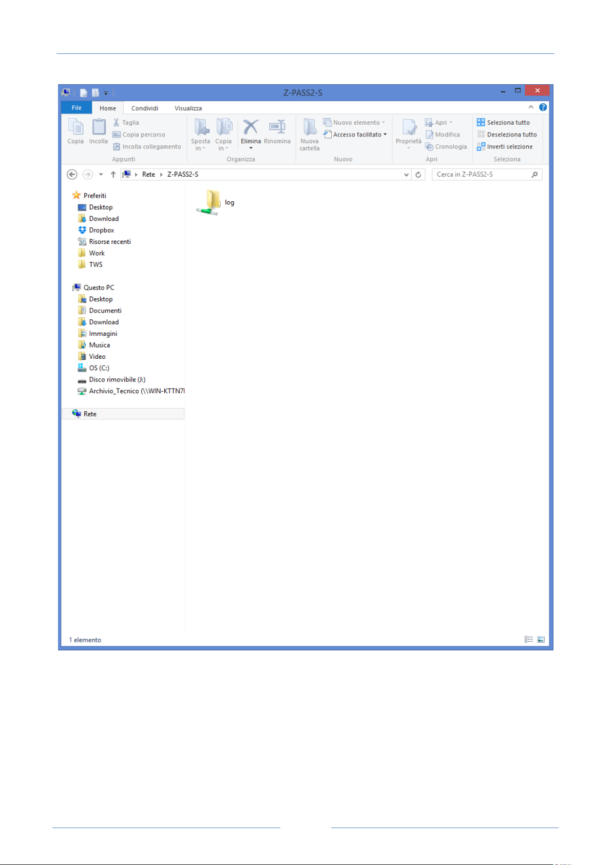
USER MANUAL – Z-TWS4/Z-PASS2-S/S6001-RTU
68
Page 69
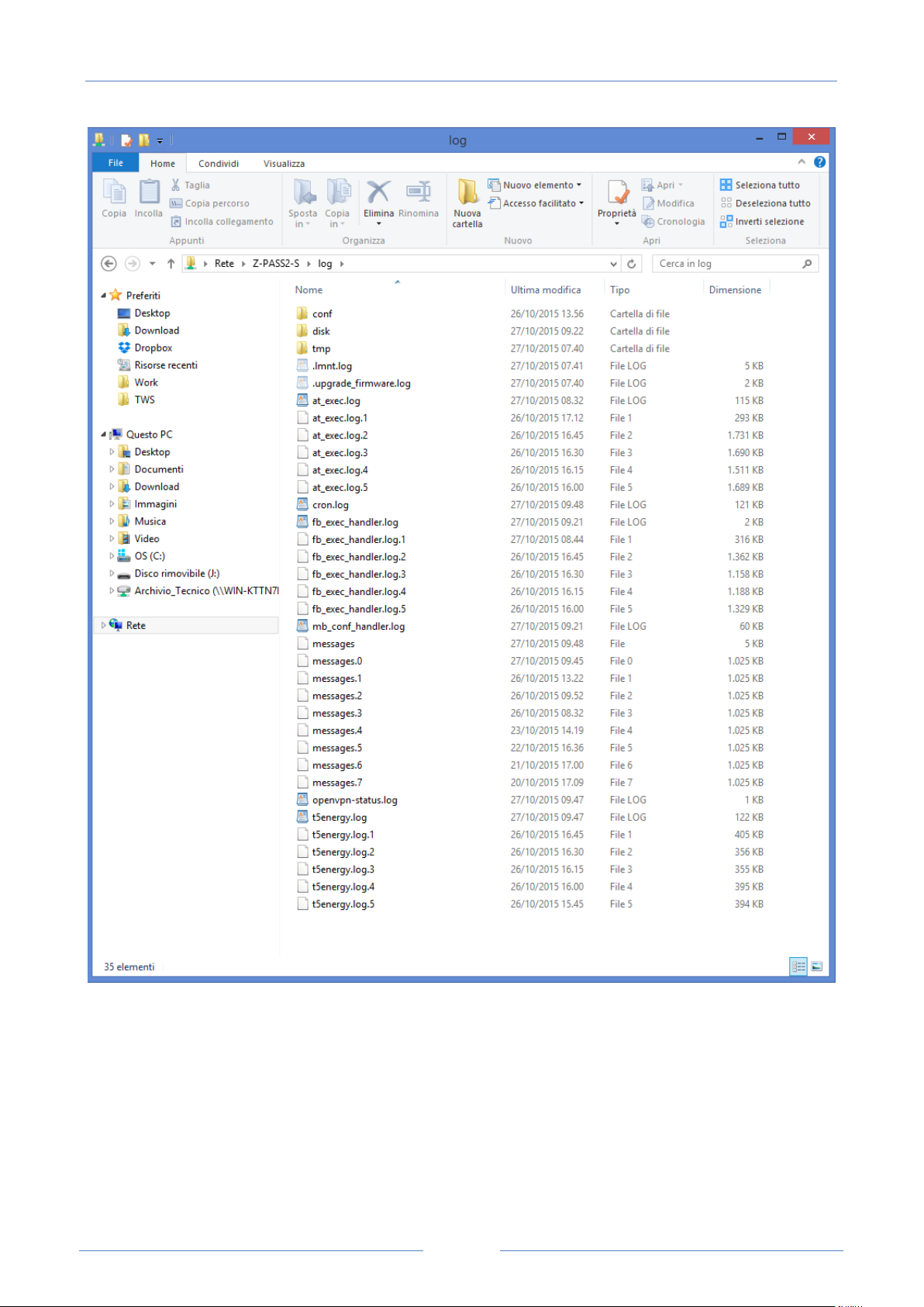
USER MANUAL – Z-TWS4/Z-PASS2-S/S6001-RTU
69
Depending on the LAN configuration, a login may be needed to access the shared folder; if so, use the
credentials shown in the following figure (username: “\guest”, password: “” [empty]).
18.1.3 Real T im e Clock S etu p
By clicking on the “Real Time Clock Setup” link, in the “General Configuration” menu, you come to the
following page:
Page 70
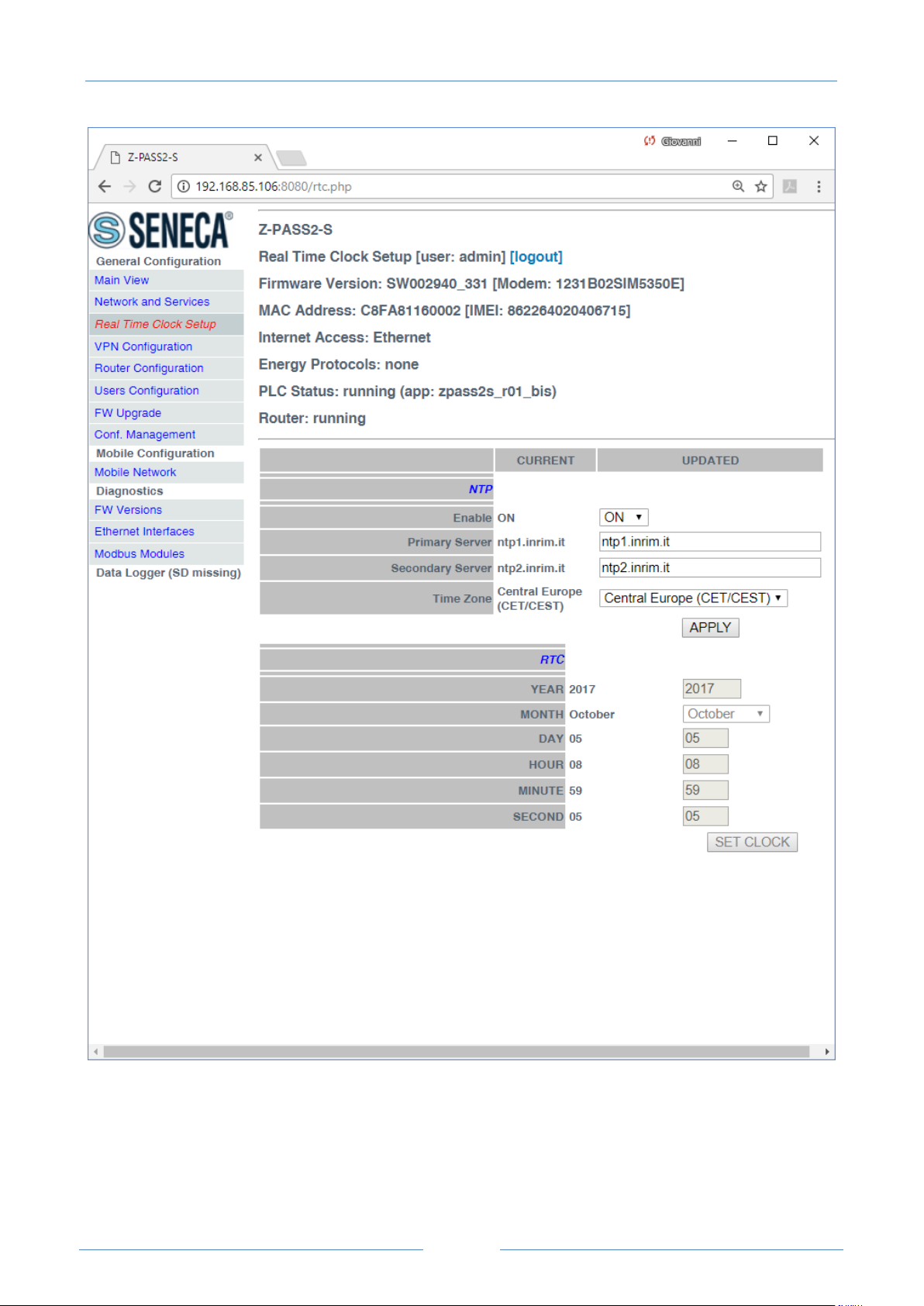
USER MANUAL – Z-TWS4/Z-PASS2-S/S6001-RTU
70
This page is made up of two sections: “NTP” and “RTC”.
In the “NTP” section, you can change the parameters related to the Network Time Protocol and to the Time
Zone, as listed in the following table:
Page 71
USER MANUAL – Z-TWS4/Z-PASS2-S/S6001-RTU
71
Field
Meaning
Default value
NTP/Enable
Flag to enable/disable time
synchronization by means of NTP
protocol
ON
NTP/Primary Server
IP address or FQDN12 of the Primary
NTP Server
ntp1.inrim.it
NTP/Secondary Server
IP address or FQDN of the Secondary
NTP Server
ntp2.inrim.it
NTP/Time Zone
Time Zone
Central Europe (CET/CEST)
12
When the “Time Zone” parameter is set to “Central Europe (CET/CEST)” value, the Device automatically
enables (CEST) / disables (CET) the “Daylight Saving Time” setting.
A large number of Time Zones are available, as partially shown in the following figure:
FQDN: Fully Qualified Domain Name, e.g.: “pool.ntp.org”.
Page 72
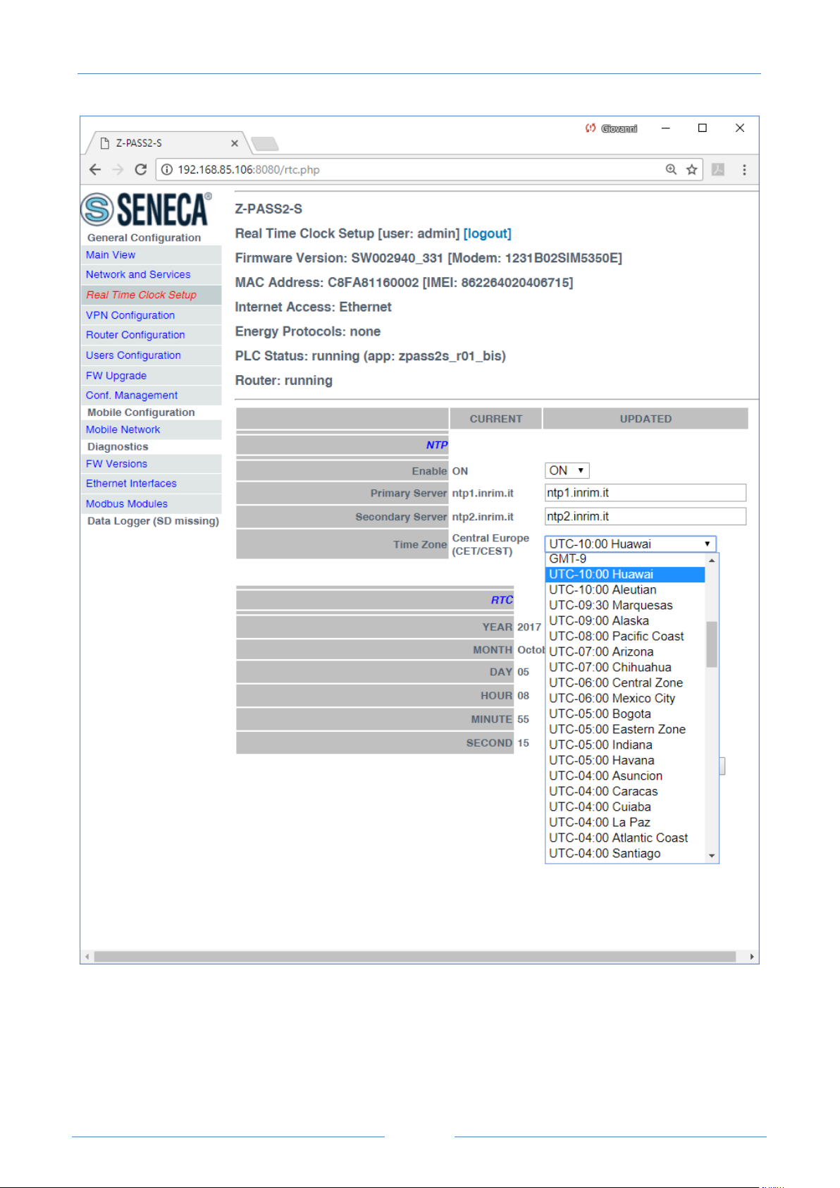
USER MANUAL – Z-TWS4/Z-PASS2-S/S6001-RTU
72
The “RTC” section of the page lets you manually change the Device date/time settings; since this makes
sense only if NTP time synchronization is not enabled, when “NTP/Enable” parameter is “ON” the input
fields and the “SET CLOCK” button are disabled and the parameters are only for viewing.
Instead, when “NTP/Enable” parameter is “OFF”, the input fields in the “NTP” section are still enabled; this
lets you change and save the parameter values, even if they are not actually used.
Page 73
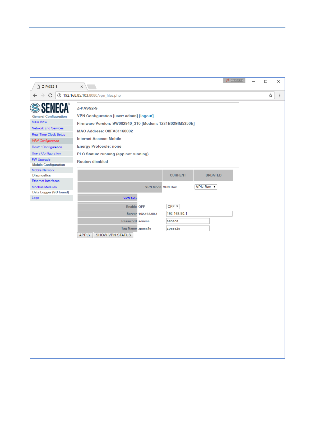
USER MANUAL – Z-TWS4/Z-PASS2-S/S6001-RTU
73
18.1.4 VPN Conf igu r ation
By clicking on the “VPN Configuration” link, in the “General Configuration” menu, you come to the
following page:
The page has a different layout depending on the value of the “VPN Mode” parameter, which can be
“OpenVPN” or “VPN Box” (for an explanation of these values, see chapter 10).
18.1.4.1 OpenVPN
The page is made up of two sections: “VPN Files” and “VPN Configuration”.
Page 74
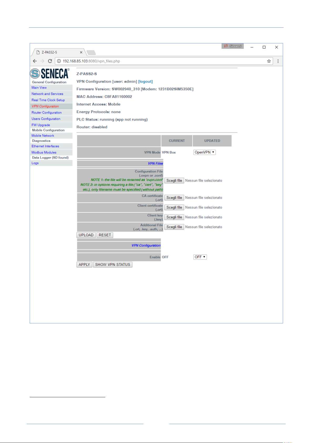
USER MANUAL – Z-TWS4/Z-PASS2-S/S6001-RTU
74
13
The “VPN Files” section lets you load the files needed to configure Open VPN and establish a secure VPN
connection; these files are described in the following.
18.1.4.1.1 Configuration File
This file shall contain all the information needed to configure the Open VPN behaviour; the main
configuration options are13:
if the Device shall act as a client or a server (typically, it will be a client)
For more information about Open VPN configuration options, please refer to the OpenVPN web page
(“openvpn.net”).
Page 75

USER MANUAL – Z-TWS4/Z-PASS2-S/S6001-RTU
75
the transport protocol (UDP or TCP)
the server IP address/host name and port
the files needed to perform authentication procedures
etc.
This file has the .ovpn extension (in Windows systems) or .conf extension (in Linux systems); regardless of
the original name, it will be renamed as ovpn.conf on the Device.
This is the only mandatory file, that is if this file has not been loaded on the Device, VPN can’t be enabled.
As reminded in the web page, in options requiring a file argument, only the file name shall be given, with
no path, as in the following example:
ca ca.crt OK
ca /home/config/vpn/ca.crt KO !
Other two important rules that shall be followed are:
the “dev” option shall be: “dev tun0” or “dev tap0”
the “log” option shall be omitted (so that, logs are written to syslog)
An example of a client configuration file is given in paragraph 18.1.4.1.7.
18.1.4.1.2 CA certificate
This file shall contain the Certification Authority (CA) certificate and has the .crt extension.
It is needed when the configuration file contains the “ca” option.
18.1.4.1.3 Client certificate
This file shall contain the client certificate and has the .crt extension.
It is needed when the configuration file contains the “cert” option.
18.1.4.1.4 Client key
This file shall contain the client key and has the .key extension.
It is needed when the configuration file contains the “key” option.
18.1.4.1.5 Additional file
This file can be of any type and may be needed for configuration options other than “ca”, “cert” and “key”.
More than one additional file can be loaded.
You can browse your PC to select the above files and send them to the Device by pressing the “UPLOAD”
button.
Once the upload is done, a result page is shown like in the following figure.
Page 76
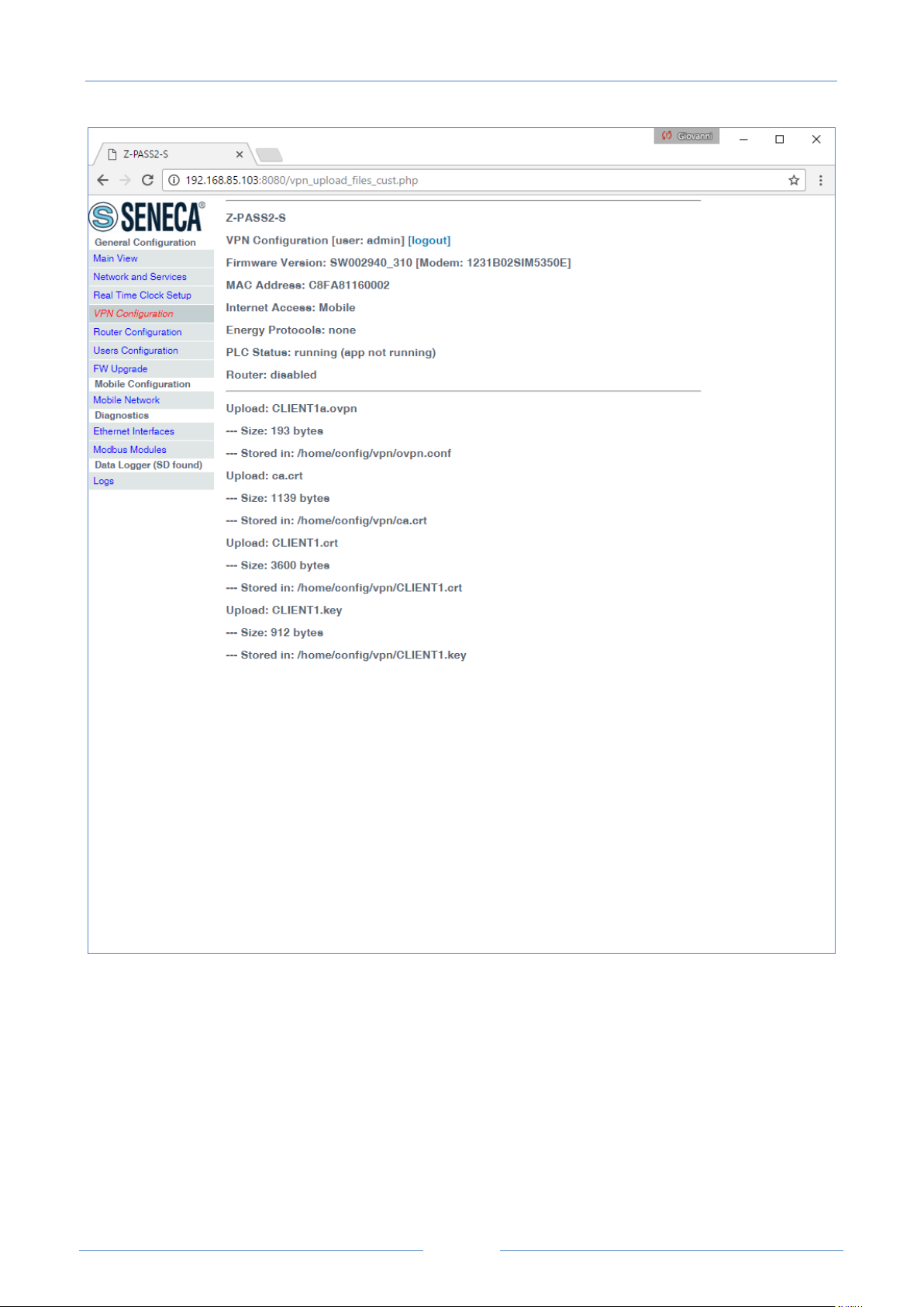
USER MANUAL – Z-TWS4/Z-PASS2-S/S6001-RTU
76
Page 77
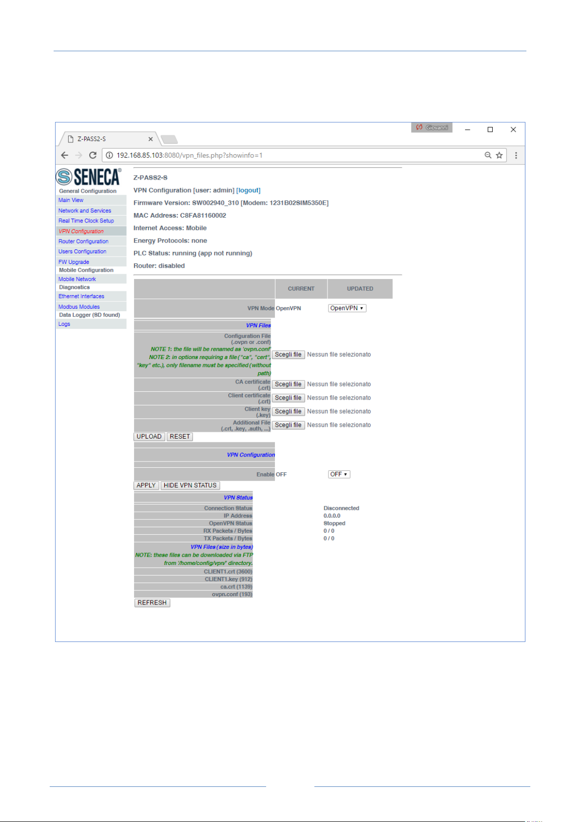
USER MANUAL – Z-TWS4/Z-PASS2-S/S6001-RTU
77
You can check which VPN files are stored on the Device by clicking on the “SHOW VPN STATUS” button, as
shown in the following figure (remember that the configuration file is renamed as “ovpn.conf”):
As reminded by the web page, the VPN files can be downloaded from the Device, if needed, via FTP/SFTP;
they can be found in the /home/config/vpn directory, as shown in the following figure.
Page 78
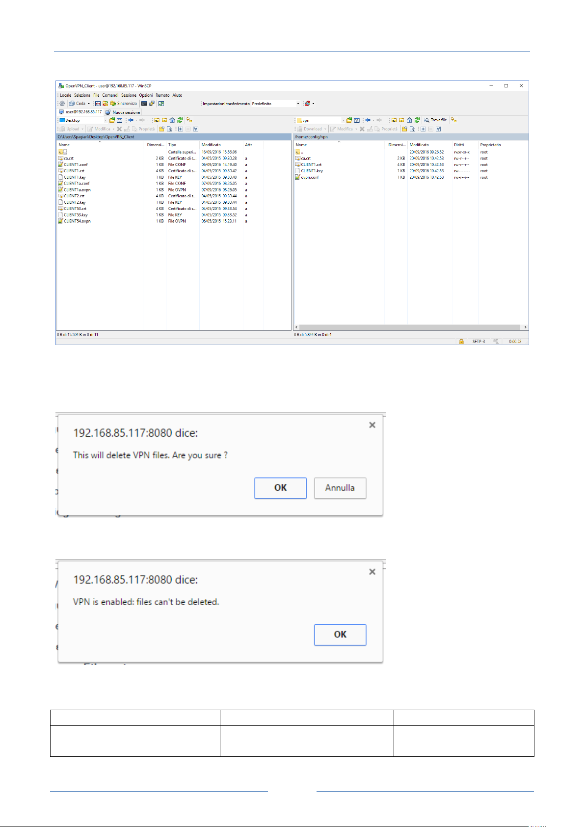
USER MANUAL – Z-TWS4/Z-PASS2-S/S6001-RTU
78
Field
Meaning
Default value
VPN Configuration/Enable
Flag to enable/disable the VPN
connectivity; when enabled, the
OFF
Is is possible to clear all the VPN files, by clicking on the “RESET” button; a pop-up will appear, requiring a
confirmation:
If VPN is enabled, the user is not allowed to delete VPN files, as warned by the following pop-up:
In the “VPN Configuration” section, there is only one parameter, as described in the following table:
Page 79
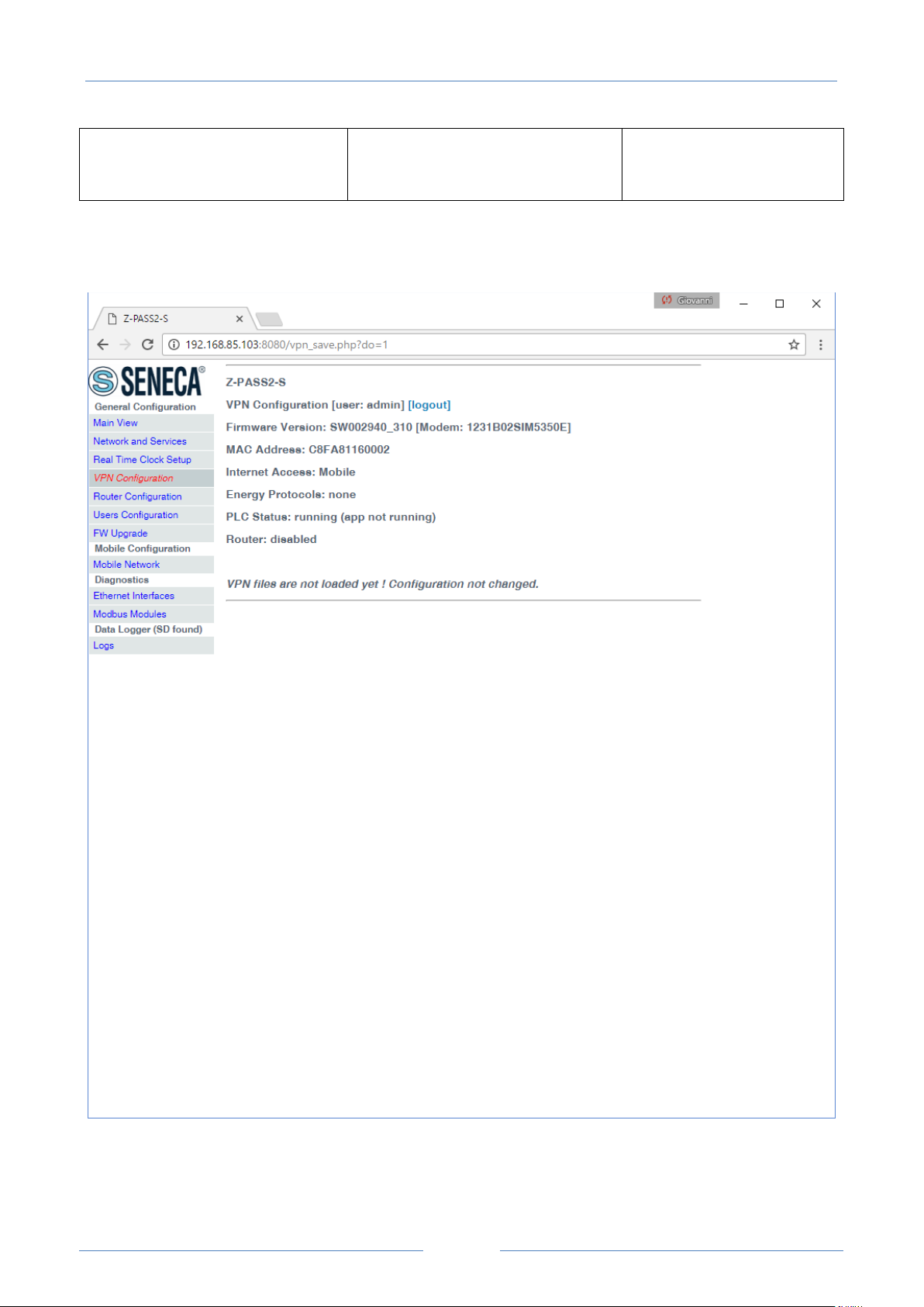
USER MANUAL – Z-TWS4/Z-PASS2-S/S6001-RTU
79
Device will run the Open VPN
process with the loaded
configuration
As already told above, if you try to enable the VPN connectivity, but no configuration file has been
uploaded to the Device yet, an error is given as shown in the following figure:
When you click on the “SHOW VPN STATUS” button, a third section appears, named “VPN Status”, showing:
the VPN “Connection Status” (i.e.: “Disconnected” or “Connected”)
Page 80
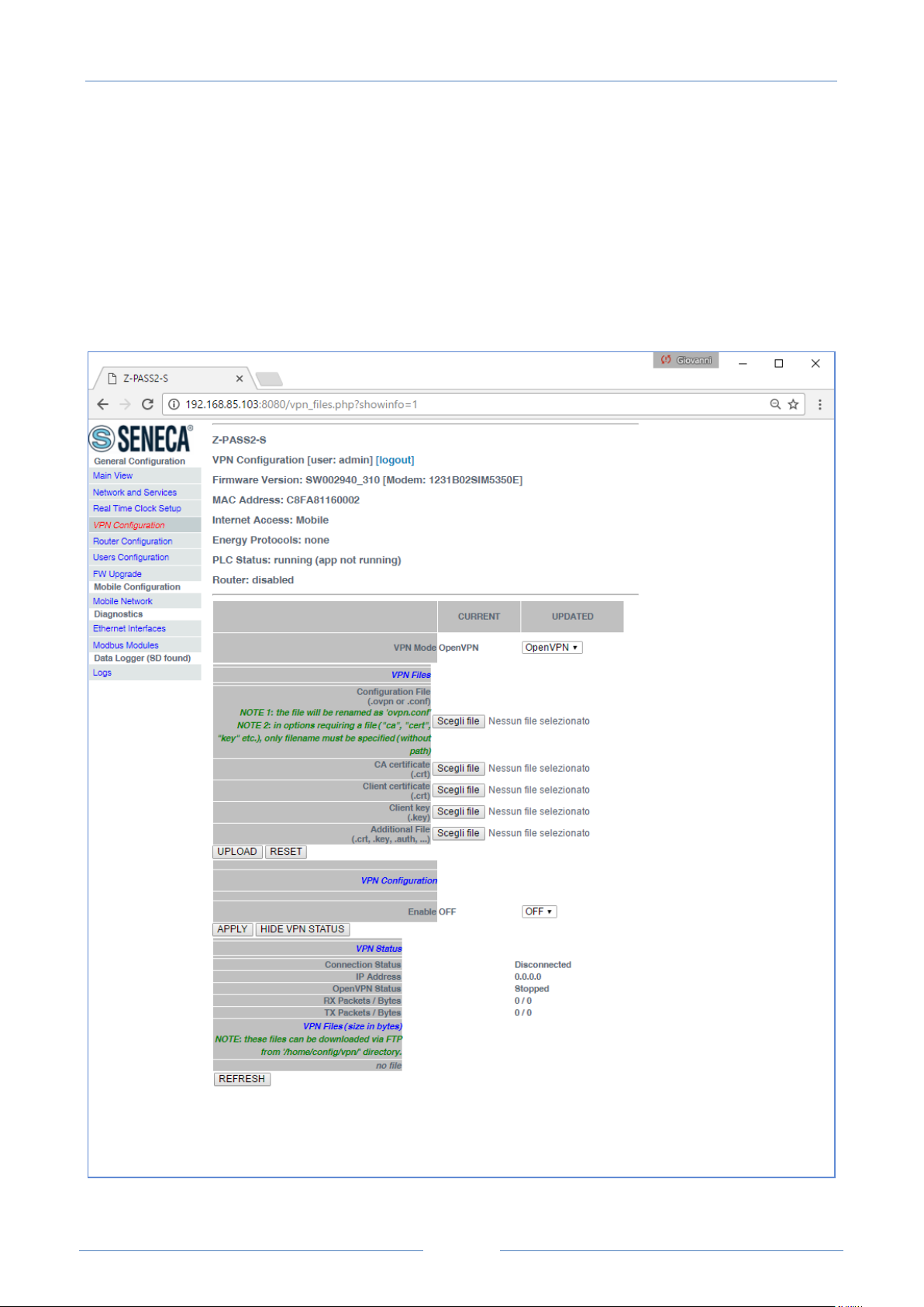
USER MANUAL – Z-TWS4/Z-PASS2-S/S6001-RTU
80
the IP address assigned to the VPN interface when “Connected”, the “dummy” IP address “0.0.0.0”
when “Disconnected”
the “OpenVPN Status” (i.e.: “Stopped” or “Running”)
the number of packets/bytes received from the VPN interface, when connected; “0/0” when
disconnected
the number of packets/bytes sent to the VPN interface, when connected; “0/0” when disconnected
the VPN files stored on the Device (see above)
as shown in the following couple of figures:
Page 81
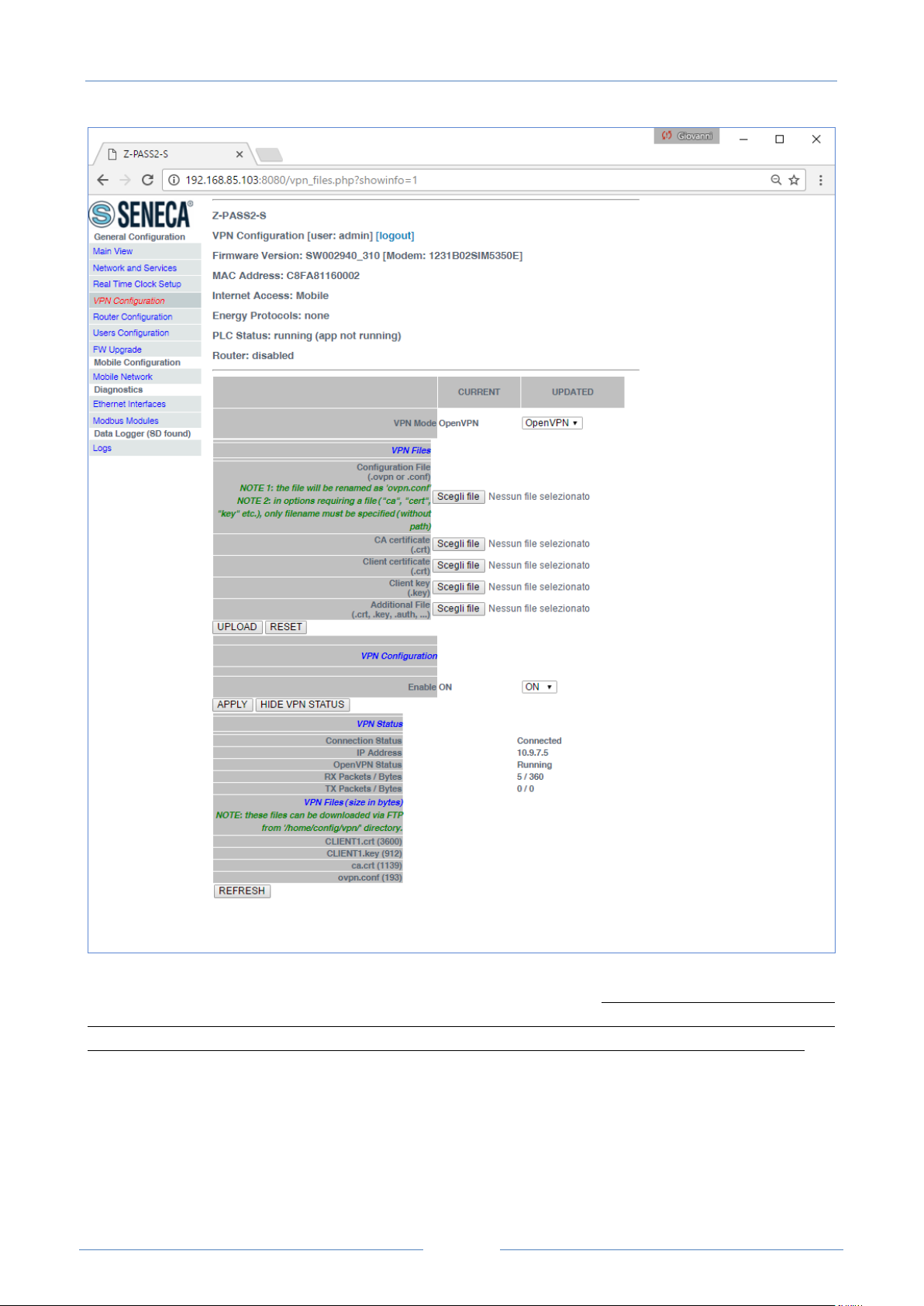
USER MANUAL – Z-TWS4/Z-PASS2-S/S6001-RTU
81
An important status information is given by the “OpenVPN Status” field; if VPN is enabled (“ON”), but this
status is “Stopped”, Open VPN process could not be correctly started: probably, the configuration file
contains some errors or, maybe, some options not supported by the Device Open VPN implementation.
You can refresh the VPN status, by clicking on the “REFRESH” button.
Finally, you can hide the “VPN Status” section, by clicking on the “HIDE VPN STATUS” button.
Page 82

USER MANUAL – Z-TWS4/Z-PASS2-S/S6001-RTU
82
LED
Status
Meaning
VPN Yellow
ON
Blinking
VPN connection is working properly
VPN connection is not working properly
18.1.4.1.6 OpenVPN Server configuration file
This paragraph gives an example of OpenVPN server configuration; this is the server configuration typically
used with Z-TWS4/Z-PASS2-S/S6001-RTU devices.
port 1194
proto udp
dev tun
ca ca.crt
cert server.crt
key server.key
dh dh1024.pem
server 10.9.7.0 255.255.255.0
ifconfig-pool-persist ipp.txt
client-config-dir ccd
client-to-client
keepalive 10 120
comp-lzo
persist-key
persist-tun
status openvpn-status.log
verb 3
18.1.4.1.7 OpenVPN Client configuration file
This paragraph gives an example of OpenVPN client configuration; this is the client configuration typically
loaded on Z-TWS4/Z-PASS2-S/S6001-RTU devices.
client
dev tun
port 1194
proto udp
remote 2.192.5.105 1194
nobind
ca ca.crt
cert tws4.crt
key tws4.key
comp-lzo
persist-key
persist-tun
script-security 3 system
verb 3
18.1.4.1.8 LED signalling (Z-PASS2-S-R01/Z-PASS2-S-IO/Z-TWS4-IO)
In Z-PASS2-S-R01/Z-PASS2-S-IO/Z-TWS4-IO products, when VPN functionality is enabled in “OpenVPN”
mode, the “SERV” and “VPN“ LEDs give the following status information (see chapter 5):
Page 83

USER MANUAL – Z-TWS4/Z-PASS2-S/S6001-RTU
83
OFF
VPN functionality is disabled
SERV Green
-
Not used
18.1.4.2 VPN Box
The page contains only ony section: “VPN Box”, as shown in the following figure.
Page 84
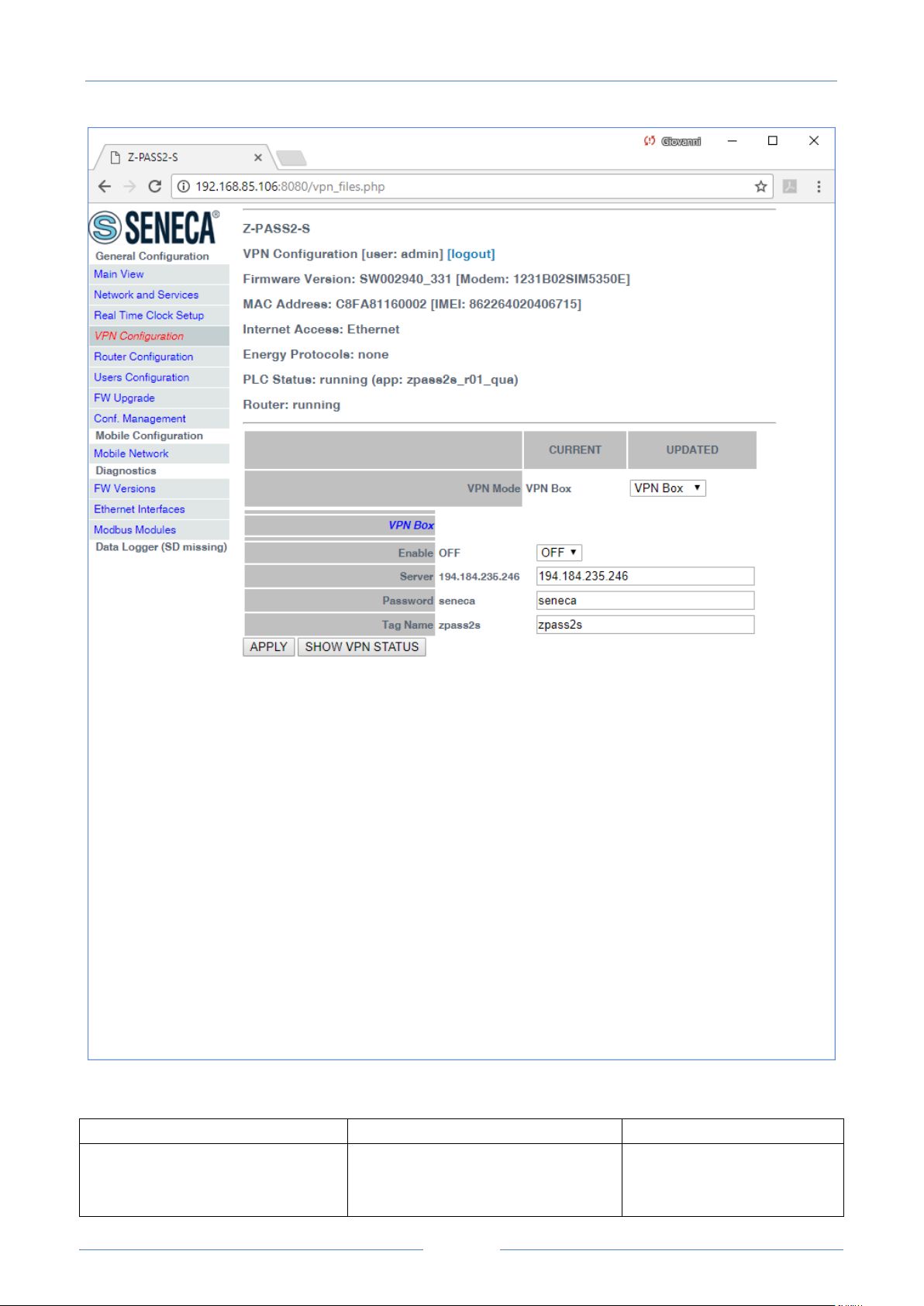
USER MANUAL – Z-TWS4/Z-PASS2-S/S6001-RTU
84
Field
Meaning
Default value
VPN BOX/Enable
Flag to enable/disable the “VPN
Box” functionality, that is the
procedure/protocol that lets the
OFF
The “VPN Box” section contains the following parameters:
Page 85

USER MANUAL – Z-TWS4/Z-PASS2-S/S6001-RTU
85
Device setup the VPN, by interacting
with the “VPN Box” server (see “VPN
Box User Manual”)
VPN BOX/Server
IP address or FQDN of the “VPN Box”
server
192.168.90.1
VPN BOX/Password
Password to access the “VPN Box”
server
seneca
VPN BOX/Tag Name
Mnemonic name used to uniquely
identify the Device; if the default
(“zpass2s”) value is left, the Device
will register as
“zpass2s_<MACAddress>” or
“ztws4_<MACAddress>” on the VPN
Box
zpass2s
When you click on the “SHOW VPN STATUS” button, a new section appears, named “VPN Status”, showing:
the VPN “Connection Status” (i.e.: “Disconnected” or “Connected”)
the IP address assigned to the VPN interface when “Connected”, the “dummy” IP address “0.0.0.0”
when “Disconnected”; this row is not shown for “Point-to-Point (L2)” VPN Box, since no IP address
is assigned to the VPN interface
the “OpenVPN Status” (i.e.: “Stopped” or “Running”)
the number of packets/bytes received by the VPN interface, when connected; “0/0” when
disconnected
the number of packets/bytes sent by the VPN interface, when connected; “0/0” when disconnected
the “VPN Box Type”, which can be “Point-to-Point”, “Point-to-Point (L2)” or “Single LAN”, if VPN
Box is enabled
the “VPN Box Status”, if VPN Box is enabled
the username of the connected user, if any
as shown in the following three figures:
Page 86
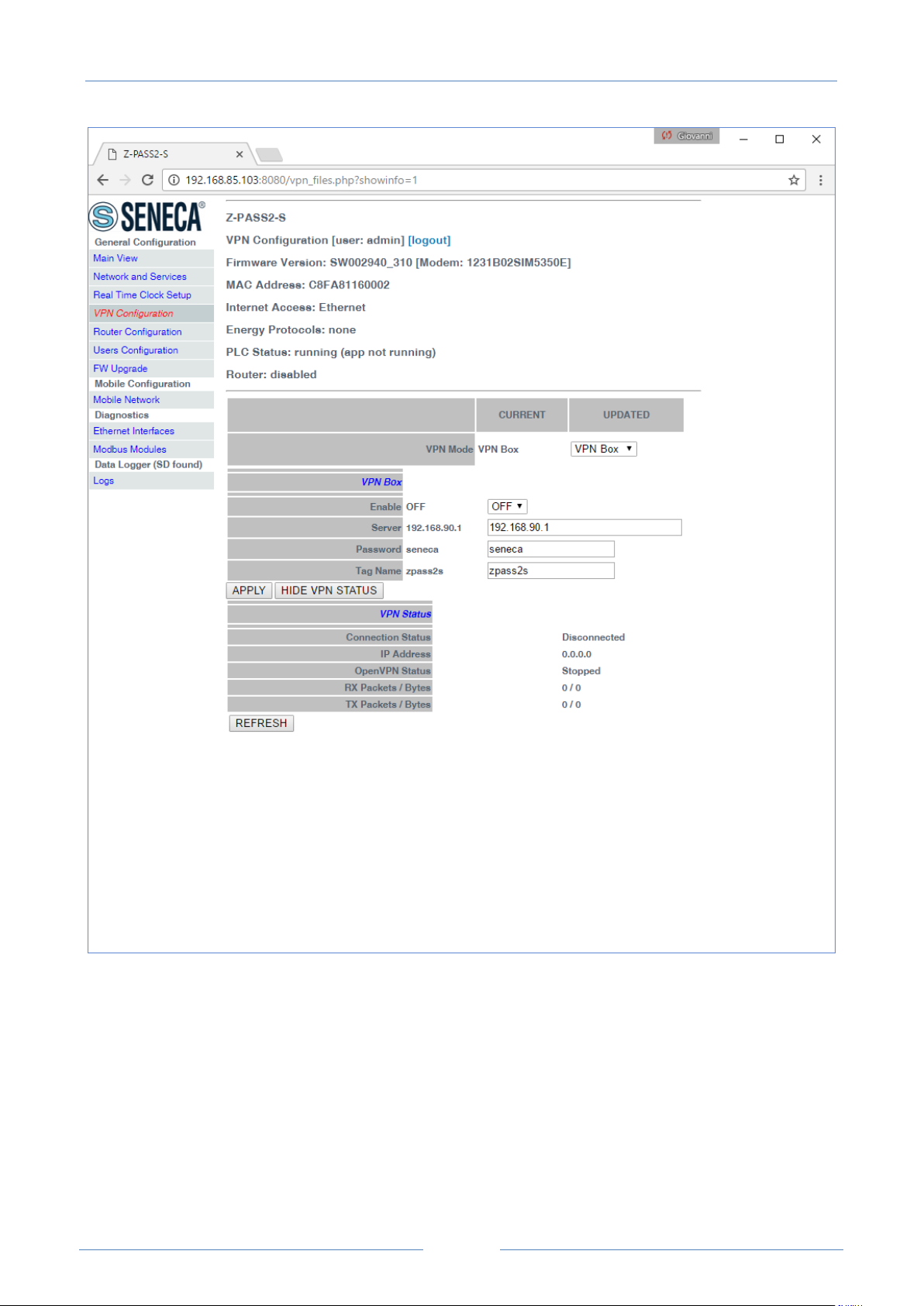
USER MANUAL – Z-TWS4/Z-PASS2-S/S6001-RTU
86
Page 87
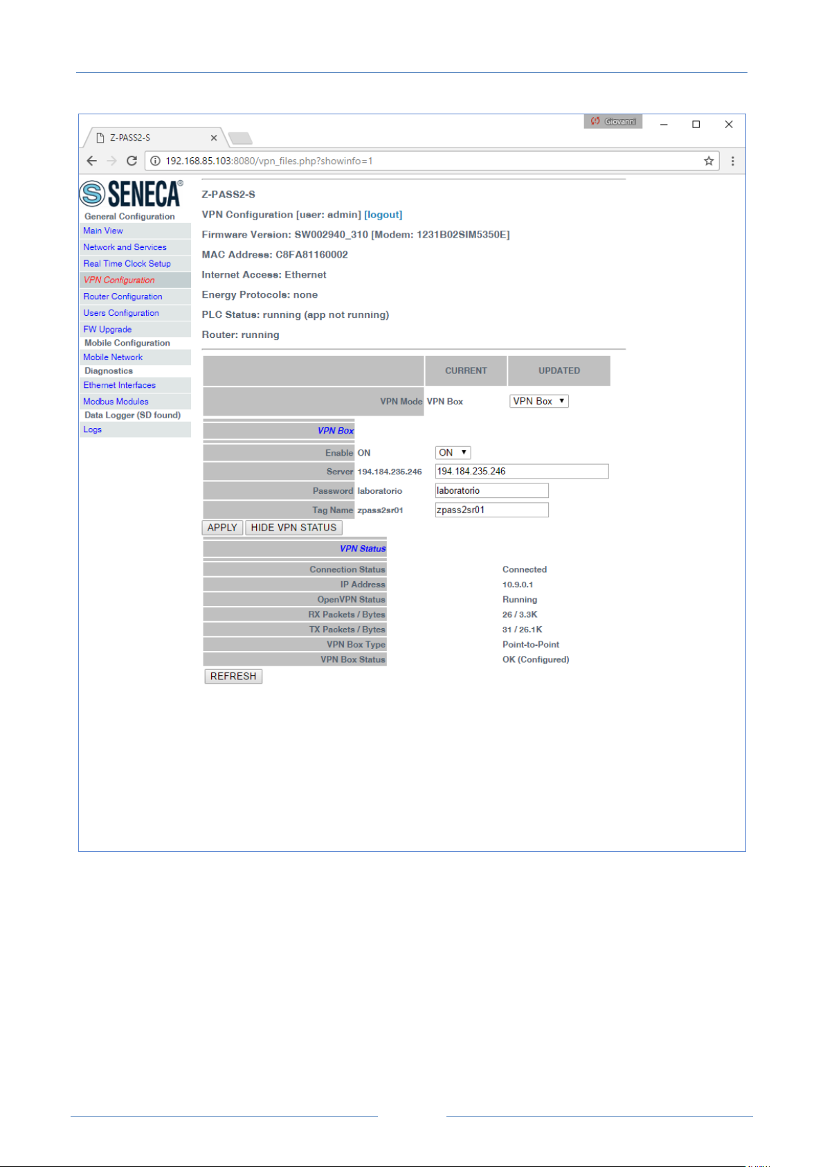
USER MANUAL – Z-TWS4/Z-PASS2-S/S6001-RTU
87
Page 88
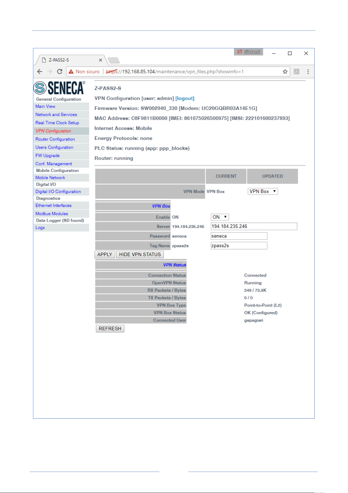
USER MANUAL – Z-TWS4/Z-PASS2-S/S6001-RTU
88
For an explanation of the differences between a “Single LAN” VPN and a “Point-to-Point” VPN, see chapter
10.
The “VPN Box Status” string has the following format:
Page 89
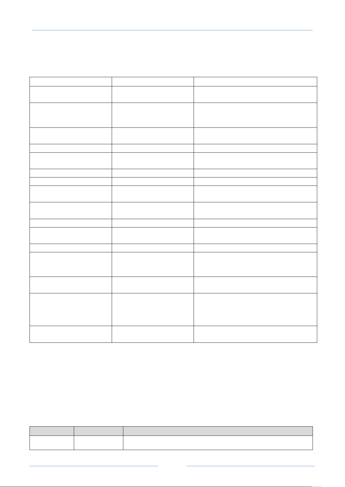
USER MANUAL – Z-TWS4/Z-PASS2-S/S6001-RTU
89
Result
Status
Meaning
Error (Unexpected response)
A response code has been received that is not
handled by the Device (it should never occur)
Error (No response from VPN
Box)
No response has been received from the VPN Box
(response timeout); this is normally due to
connectivity problems
Error (Invalid response from
VPN Box)
A response has been received whose content is
not valid for the Device (it should never occur)
Error (Wrong password)
The password set on the Device is wrong
Error (License Limit Reached)
The maximum number of devices allowed by the
license are already registered on VPN Box
Error (VPN Box not configured)
The VPN Box has not been configured yet
Error (Generic error)
A generic error has occurred on the VPN Box
OK The Device has just been registered on the VPN
Box
OK
New
The Device is registered on the VPN Box, but it is
not configured yet (“Single LAN” only)
OK
Configuration updated
The Device configuration has just been updated
OK
Configured
The Device is properly configured and available
for VPN connection
OK
Ban
The Device has been banned
OK
Not found
The Device is unknown for the VPN Box; this
happens when Device registration is deleted on
the VPN Box
OK
Unknown
The Device has an “unknown” status in the VPN
Box (it should never occur)
OK
Not bound
The “tunnel” between the Device and the VPN
Box is not up; this may occur when the tunnel
port is blocked (“not open”) in the ADSL router
on the VPN Box side (“Point-to-Point” only)
OK
Unexpected status
A status code has been received that is not
handled by the Device (it should never occur)
LED
Status
Meaning
VPN Yellow
ON
VPN connection is working properly
Result (Status)
The following table gives a short explanation of the possible “Result” and “Status” strings:
You can refresh the VPN status, by clicking on the “REFRESH” button.
Finally, you can hide the “VPN Status” section, by clicking on the “HIDE VPN STATUS” button.
18.1.4.2.1 LED signalling (Z-PASS2-S-R01/Z-PASS2-S-IO/Z-TWS4-IO)
In Z-PASS2-S-R01/Z-PASS2-S-IO/Z-TWS4-IO products, when VPN functionality is enabled in “VPN Box/Single
LAN” mode, the “SERV” and “VPN“ LEDs give the following status information (see chapter 5):
Page 90

USER MANUAL – Z-TWS4/Z-PASS2-S/S6001-RTU
90
Blinking
OFF
VPN connection is not working properly
The Device has not been configured by the VPN Box yet or VPN Box
functionality is disabled
SERV Green
ON
Blinking
OFF
VPN Box “SERVICE” connection is working properly
VPN Box “SERVICE” connection is not working properly
VPN Box functionality is disabled
LED
Status
Meaning
VPN Yellow
ON
OFF
A VPN client is connected to the Device
No VPN client is connected to the Device or VPN Box functionality is disabled
SERV Green
ON
Blinking
OFF
VPN Box “SERVICE” connection is working properly
VPN Box “SERVICE” connection is not working properly
VPN Box functionality is disabled
Similarly, when VPN functionality is enabled in “VPN Box/Point-to-Point” mode, the “SERV” and “VPN“ LEDs
give the following status information (see chapter 5):
18.1.5 Rou t e r C o n f i gu r at ion
By clicking on the “Router Configuration” link, in the “General Configuration” menu, you come to the
following page:
Page 91
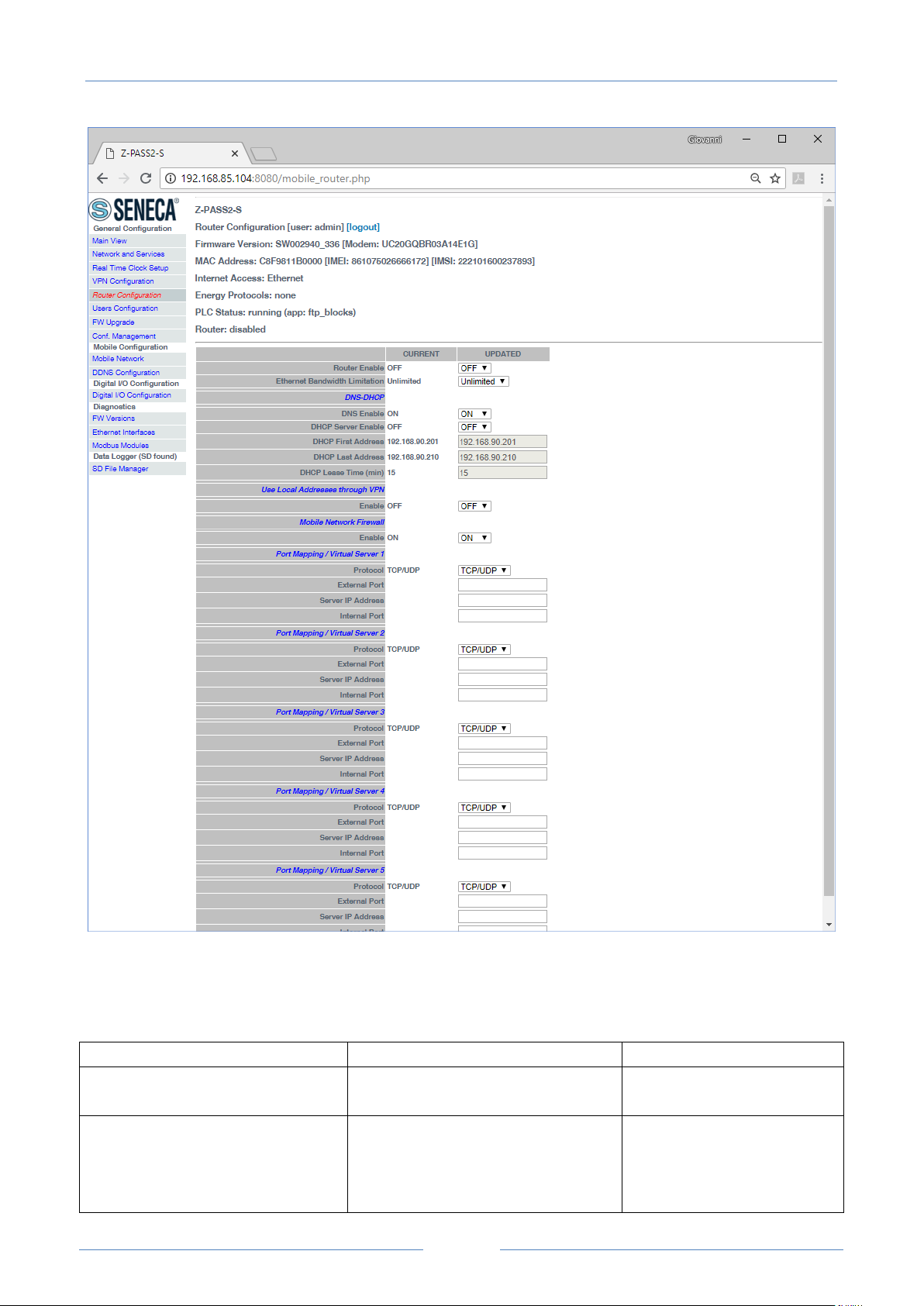
USER MANUAL – Z-TWS4/Z-PASS2-S/S6001-RTU
91
Field
Meaning
Default value
Router Enable
Flag to enable/disable the Router
functionality
OFF
Ethernet Bandwidth Limitation
This parameter can be used to limit
the bandwidth on the ethernet
interfaces; this may be needed to
avoid overloading the CPU, when a
Unlimited
In this page, you can change the parameters related to the Router functionality.
First, you have a set of general parameters, as listed in the following table:
Page 92

USER MANUAL – Z-TWS4/Z-PASS2-S/S6001-RTU
92
large amount of data is forwarded
from one interface to the other (LAN
↔ WAN).
Since this does not occur when the
two ethernet interfaces work in
“switch” mode, the parameter is not
shown when “Ethernet Mode”
parameter is set to “Switch” (see
paragraph 18.1.2).
Possible values are:
Unlimited
20 Mbit/s
10 Mbit/s
1 Mbit/s
DNS Enable
Flag to enable/disable the DNS
forwarding service
ON
DHCP Server Enable
Flag to enable/disable the DHCP
service (DHCP server)
NOTE: this parameter can be set to
“ON” only if the “DHCP” parameter
of the “Network and Services” page
is set to “OFF”.
OFF
DHCP First Address
DHCP Last Address
These parameters define the range
of IP addresses assigned by the
DHCP server to requesting clients
192.168.90.201
192.168.90.210
DHCP Lease Time (min)
Validity period for the IP address
assignment, in minutes.
Possible values are in the range
[1..60].
15
Field
Meaning
Default value
Use Local Addresses Through VPN
Flag to enable/disable the access to
the Device and other devices which
are in the Device LAN by using their
local (LAN) IP addresses
OFF
Field
Meaning
Default value
Mobile Network Firewall/Enable
Flag to enable/disable the “Mobile
Network Firewall”, that is
disable/enable access to the Device
and other devices which are in the
Device LAN, by using the IP address
ON
Then, you have the parameter shown in the following table.
Then, you have another important parameter, which is shown in the following table.
Page 93

USER MANUAL – Z-TWS4/Z-PASS2-S/S6001-RTU
93
assigned to the Mobile Network (3G)
interface.
To open a port in the firewall, a
“Port Mapping / Virtual Server” rule
shall be defined.
The above parameter shall be set to ON, to protect the Device against undesired (maybe malicious)
accesses.
This is the only parameter in the “Router Configuration” page that is working also when the Router
functionality is disabled (Router Enable = OFF).
It is important to note that, when the VPN is activated (see 18.1.4 paragraph), the parameter is
automatically set to ON, as warned by the message shown in the following figure.
Page 94
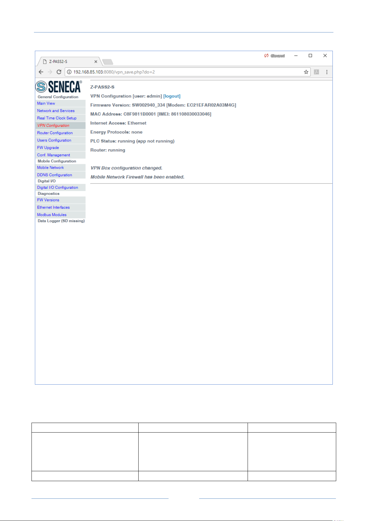
USER MANUAL – Z-TWS4/Z-PASS2-S/S6001-RTU
94
Field
Meaning
Default value
Protocol
This parameter defines the transport
protocol (or kind of port) which is
affected by the rule: TCP, UDP or
both
TCP/UDP
External Port
TCP or UDP port which a packet was
Empty
Finally, there are 5 sections which let you define up to 5 “Port Mapping” rules (also known as “Virtual
Servers”); in each section, the available parameters are the following:
Page 95

USER MANUAL – Z-TWS4/Z-PASS2-S/S6001-RTU
95
originally sent to
Server IP Address
IP address which the received packet
is forwarded to
Empty
Internal Port
TCP or UDP port which the received
packet is forwarded to
Empty
If Router is left disabled (Router Enabled = OFF), you can still change parameters; changes will be saved
without actually applying them (except for the “Mobile Network Firewall” parameter, as told before); the
following message will be given, after clicking the “APPLY” button:
Page 96
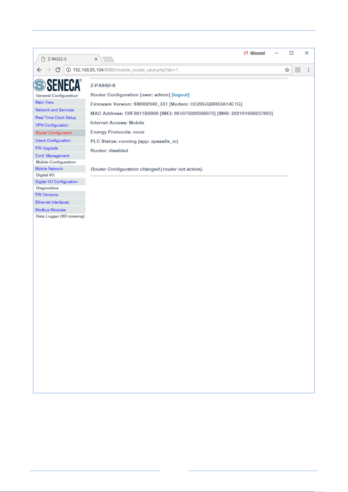
USER MANUAL – Z-TWS4/Z-PASS2-S/S6001-RTU
96
If you try to enable the DHCP server functionality (DHCP Server Enable = ON), but the “DHCP First Address”
and “DHCP Last Address” parameters define an address range that is not congruent with the Ethernet
configuration (IP address and network mask), an error is given, as shown in the following figure:
Page 97
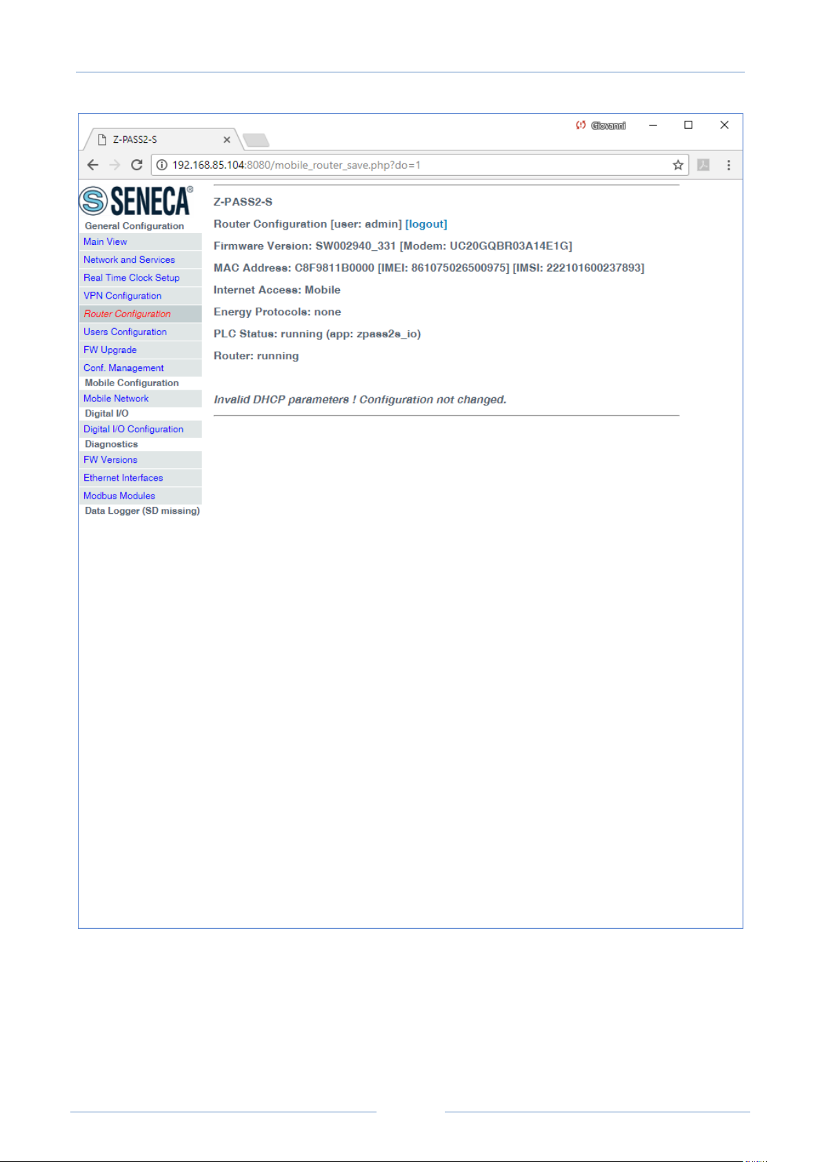
USER MANUAL – Z-TWS4/Z-PASS2-S/S6001-RTU
97
As already told before, the Router configuration page lets you define up to 5 “Port Forwarding” rules or
“Virtual Servers”.
An example is given in the following figure:
Page 98
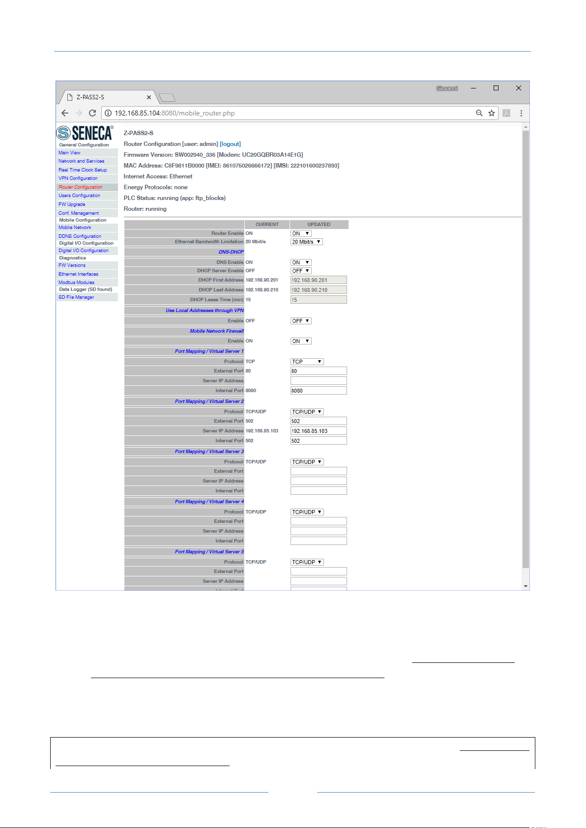
USER MANUAL – Z-TWS4/Z-PASS2-S/S6001-RTU
98
In this example, 2 rules have been set:
the first rule tells the Device that any TCP packet received on the 80 (HTTP) port has to be
forwarded to the 8080 port, leaving the original destination IP address unchanged; so, this rule lets
you access the Device configuration web site on the standard HTTP port; however, by doing this,
the access to the custom user’s pages won’t be possible anymore !
the second rule tells the Device that any TCP or UDP packet received on the 502 port (which is
often used for Modbus TCP protocol) shall be forwarded to the 192.168.85.103 IP address (which
corresponds to another device) on the same (502) destination port.
Another important aspect of “Port Mapping / Virtual Server” rules is that they let define which ports are
open in the “Mobile Network Firewall”; for example, if you want to connect to the web configuration site
Page 99
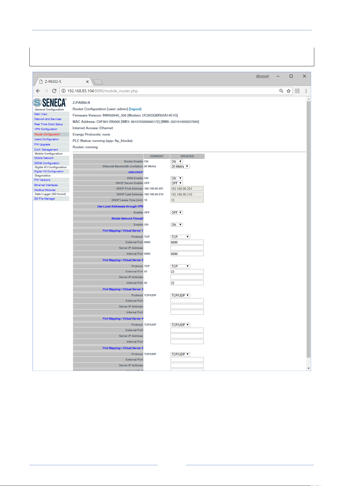
USER MANUAL – Z-TWS4/Z-PASS2-S/S6001-RTU
99
and to the SSH console, through the public IP address assigned to the 3G interface, the 8080 and 22 TCP
ports shall be open; this can be done as shown in the following figure.
18.1.6 OP C UA S erv er Conf i g u r at ion
By clicking on the “OPC UA Server Conf” link, in the “General Configuration” menu, you come to the
following page:
Page 100
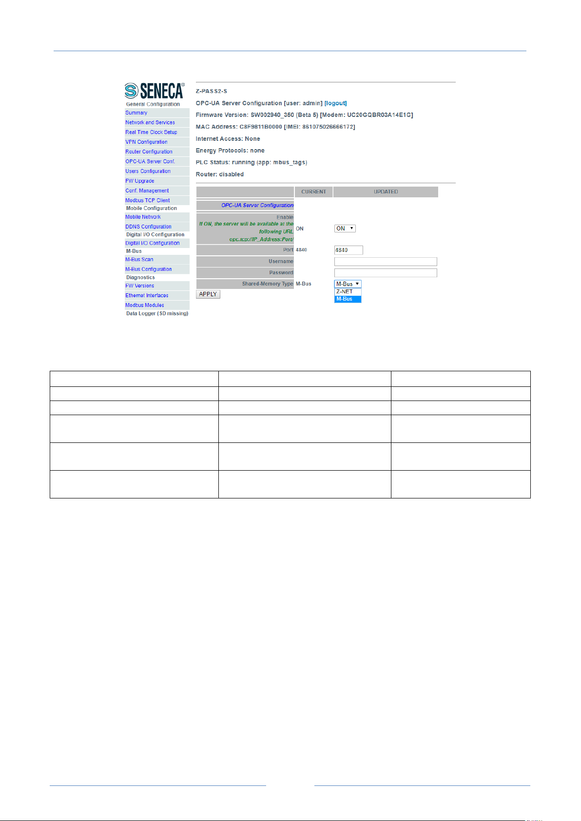
USER MANUAL – Z-TWS4/Z-PASS2-S/S6001-RTU
100
Field
Meaning
Default value
Enable
Enable or not
OFF
Port
The server port to use
4840
Username
The username provided with the service
subscription
empty
Password
The password provided with the service
subscription
empty
Shared Memory
Select which shared memory must
access with the OPC-UA protocol.
Z-NET
In this page, you can set the parameters related to the OPC Unified Architecture (OPC UA), as listed in the
following table:
Note that for access the server with a OPC UA client you must use the following url:
opc.tcp://IP_ADDR:PORT/
where:
IP_ADDR is the actual IP address
PORT is the configured port for the OPC UA server
18.1.7 Us ers Conf i g u r at ion
By clicking on the “Users Configuration” link, in the “General Configuration” menu, you come to the
following page:
 Loading...