

Page 1
Page 1
MI003790
MI003796
SENECA s.r.l.
Via Austria, 26 – 35127 –PADOVA – ITALY
Tel. +39.049.8705355 – 8705359 Fax. +39.049.8706287
Web site: www.seneca.it
Technical assistance: [email protected] (IT), [email protected] (Other)
Commercial reference: [email protected] (IT), [email protected] (Other)
This document is property of SENECA srl. Duplication and reproduction are forbidden, if not authorized. Contents of the present
documentation refers to products and technologies described in it. All technical data contained in the document may be modified
without prior notice Content of this documentation is subject to periodical revision.
To use the product safely and effectively, read carefully the following instructions before use. The product must be used only for the use
for which it was designed and built. Any other use must be considered with full responsibility of the user. The installation,
implementation and set-up is allowed only for authorized operators; these ones must be people physically and intellectually suitable.
Set up must be performed only after a correct installation and the user must perform every operation described in the installation
manual carefully. Seneca is not considered liable of failure, breakdown, accident caused for ignorance or failure to apply the indicated
requirements. Seneca is not considered liable of any unauthorized changes. Seneca reserves the right to modify the device, for any
commercial or construction requirements, without the obligation to promptly update the reference manuals.
No liability for the contents of this documents can be accepted. Use the concepts, examples and other content at your own risk. There
may be errors and inaccuracies in this document, that may of course be damaging to your system. Proceed with caution, and although
this is highly unlikely, the author(s) do not take any responsibility for that. Technical features subject to change without notice.
USER MANUAL
Z-KEY
MODBUS ETHERNET SERIAL GATEWAY
AND SERIAL DEVICE SERVER
Page 2

USER MANUAL – Z-KEY
2
Date
Revision
Notes
06/02/2015
00
First revision.
31/03/2015
01
Added Export tag setup Webserver function, added
Seneca discovery and Easy Z-KEY utilities.
08/04/2015
02
Added Glossary.
Added Z-modem protocol issue through internet
Minor fix
14/07/2015
03
Added support for 7 bits Uarts (from SW004100_105)
20/11/2015
04
Added CGI command chapter
18/05/2016
05
Added Gateway Optimzed function from revision
Firmware 4100_108
Added Chapter Easy Setup APP for Android
Added Chapter Seneca Discovery Device
Updated Seneca Device Discovery Chapter
01/12/2016
06
Removed WARNING about using multi TCP Clients in
Bridge mode
02/11/2017
07
Changed PDF title
Page 3

USER MANUAL – Z-KEY
3
Table of Contents
1. GLOSSARY .................................................................................................................. 7
2. INTRODUCTION ........................................................................................................... 9
2.1. Features ......................................................................................................................................................... 9
2.2. General Specification ....................................................................................................................................10
3. ELECTRICAL CONNECTIONS .................................................................................. 11
3.1. Terminal Positions ........................................................................................................................................11
4. DEBUG LEDS ............................................................................................................. 13
5. DEFAULT CONMFIGURATION ................................................................................. 14
6. ETHERNET COMMUNICATION ................................................................................. 15
6.1. Searching Z-KEY devices in a network with the Seneca Discovery Utility .......................................................15
6.2. Changing the IP address from the USB port...................................................................................................16
7. THE EMBEDDED WEBSERVER ................................................................................ 20
7.1. LAN connection to the webserver .................................................................................................................20
8. MODBUS RTU AND MODBUS TCP-IP PROTOCOL ................................................ 22
8.1. Modbus function code supported .................................................................................................................22
9. BRIDGE MODBUS TCP-IP TO MODBUS RTU.......................................................... 23
9.1. How it works .................................................................................................................................................24
9.2. Modbus Bridge Webserver configuration ......................................................................................................24
10. GATEWAY MODBUS TCP-IP / MODBUS RTU (PORT 1 AND PORT 2 MODBUS
MASTER) .......................................................................................................................... 30
10.1. How it works .................................................................................................................................................31
10.2. Modbus Gateway configuration (Port 1 and Port 2 Modus Master) ..............................................................32
10.3. Modbus Gateway Tags Setup, export and import .........................................................................................38
Page 4

USER MANUAL – Z-KEY
4
10.4. Modbus Gateway Real Time view .................................................................................................................41
10.5. Using the Microsoft Excel ™ template for Tags setup ....................................................................................41
11. GATEWAY MODBUS TCP-IP / MODBUS RTU (1 PORT MASTER AND 1 PORT
SLAVE) .............................................................................................................................. 44
11.1. How it works .................................................................................................................................................44
11.2. Gateway Modbus TCP-IP / Modbus RTU (1 port Master and 1 port Slave) Webserver configuration ............45
11.3. Modbus Gateway Tags Setup, export and import .........................................................................................52
11.4. Modbus Gateway Real Time view .................................................................................................................55
11.5. Import/Export TAGs setup ............................................................................................................................55
12. GATEWAY MODBUS TCP-IP / MODBUS RTU (2 PORT SLAVES) ...................... 58
12.1. How it works .................................................................................................................................................58
12.2. Webserver configuration Gateway Modbus TCP-IP / Modbus RTU (2 port Slaves) ........................................59
12.3. Modbus Gateway Tags Setup, export and import .........................................................................................65
12.4. Modbus Gateway Real Time view .................................................................................................................69
12.5. Using the Microsoft Excel ™ template for Tags configuration ........................................................................69
13. REMOTE SERIAL COM PORT ............................................................................... 71
13.1. How it works .................................................................................................................................................71
13.2. Remote Serial Com Port Webserver configuration ........................................................................................72
13.3. Seneca Serial to Ethernet Connect ................................................................................................................76
13.3.1. Installing Seneca Serial to Ethernet Connect driver .................................................................................... 76
13.3.2. Select the Com port for Seneca Serial to Ethernet Connect ....................................................................... 80
13.3.3. Configuring Seneca Serial to Ethernet Connect .......................................................................................... 81
13.3.4. Debugging the Connection ......................................................................................................................... 82
13.3.5. Changing the COM port number................................................................................................................. 83
14. THE CUSTOM WEBSERVER ................................................................................. 88
15. ACCESSING THE Z-KEY FROM INTERNET ......................................................... 89
16. THE KIT-USB .......................................................................................................... 91
Page 5

USER MANUAL – Z-KEY
5
17. THE RS232 DB9 CABLE ........................................................................................ 91
18. WINDOWS USB DRIVERS INSTALLATION .......................................................... 92
19. FIRMWARE UPDATE.............................................................................................. 94
19.1. Firmware Update from Webserver ...............................................................................................................94
19.2. Firmware Update from FTP server ................................................................................................................94
19.3. Firmware Update from microSD card ............................................................................................................94
20. SENECA DISCOVERY DEVICE .............................................................................. 95
21. EASY SETUP APP FOR ANDROID ........................................................................ 95
22. CGI (COMMON GATEWAY INTERFACE) COMMAND .......................................... 96
Page 6

USER MANUAL – Z-KEY
6
Seneca Z-KEY
CAUTION!
UNDER ANY CIRCUMSTANCES, SENECA S.R.L. OR ITS SUPPLIERS SHALL NOT BE RESPONSIBLE FOR
LOSS OF RECORDING DATA/INCOMES OR FOR CONSEQUENTIAL OR INCIDENTAL DAMAGE DUE
TO NEGLECT OR RECKLESS MISHANDLING OF Z-KEY, EVEN THOUGH SENECA IS WELL AWARE OF
THESE POSSIBLE DAMAGES.
SENECA, ITS SUBSIDIARIES, AFFILIATES, COMPANIES OF THE GROUP, ITS SUPPLIERS AND
RETAILERS SHALL NOT GUARANTEE THAT THE FUNCTIONS WILL SATISFY COMPLETELY
CUSTOMER’S EXPECTATIONS OR THAT Z-KEY, THE FIRMWARE AND THE SOFTWARE SHALL HAVE
NO ERRORS OR WORK CONTINUOUSLY.
Page 7

USER MANUAL – Z-KEY
7
1. Glossary
Modbus RTU
An open protocol for the serial communications developed by Modicon Inc. (AEG Schneider Automation
International S.A.S.). Simple and robust, it has since become a de facto standard communication protocol.
For more info http://www.modbus.org/specs.php
MODBUS TCP-IP
The Modbus RTU protocol with a TCP interface that runs on Ethernet.
For more info http://www.modbus.org/specs.php
MODBUS BRIDGE
A device that translates, in real time, from Modbus TCP-IP ethernet protocol to Modbus RTU serial
protocol.
MODBUS GATEWAY
A device that translate Modbus TCP-IP protocol to Modbus RTU protocol using a buffered memory (called
shared memory). The shared memory can be accessed by multiple devices through Modbus TCP-IP,
Modbus RTU, Webservers etc… but must be configured. The Modbus Gateways are used for speed-up and
for simplify a Modbus network.
SERIAL DEVICE SERVER (REMOTE COM PORT)
A device that enables devices with an RS-232, RS-422 or RS-485 serial interface to connect to an IP network.
This makes it possible to use Ethernet in place of serial cables, minimizing workstation clutter and also
allowing serial devices to be placed far away from the computers with which they are used. A Serial device
server is virtually transparent to the serial protocol.
MODBUS RTU MASTER-SLAVE
The Master is connected with one or more slaves, the slave waits for an incoming register(s) request from
the master. Only one master is allowed, for overcome this limitation you must use a Modbus gateway.
MODBUS TCP-IP CLIENT-SERVER
Page 8

USER MANUAL – Z-KEY
8
The Client (called Master in Modbus RTU) establishes a connection with the Server (called Slave in Modbus
RTU). The Server waits for an incoming connection from the Client. Once a connection is established, the
Server then responds to the registers queries from the Client.
WEBSERVER
A software that store, process and deliver web pages to clients. Clients web can be PCs, Smartphones, Tablets
with a browser (Chrome, Internet Explorer, Firefox etc…).
Page 9

USER MANUAL – Z-KEY
9
2. Introduction
Z-KEY is a serial device server, a Modbus TCP-IP to Modbus RTU Gateway and a Modbus TCP-IP to Modbus
RTU Bridge, into one product.
Two independent serial ports (one RS485 and a RS232/RS485 configurable port), a Fast Ethernet 10100MBits and an USB port are available.
The USB port can be used also like a communication port supporting the Modbus RTU protocol for
configuration purpose.
An internal Webserver is also available for configuration and real time values view, a custom webserver con
be loaded into a microSD card (not supplied).
Z-Key is configurable in 5 different modes:
Bridge Modbus TCP-IP to Modbus RTU
Gateway Modbus TCP-IP to Modbus RTU
Gateway Modbus TCP-IP to Modbus RTU (1 port slave and 1 port Master)
Gateway Modbus TCP-IP to Modbus RTU (2 ports slaves)
Remote Serial COM port
2.1. Features
Fast Ethernet port (10-100 Mbit/s)
Support for Transparent Remote Serial Port, Modbus Gateway, Modbus Bridge
Multiprotocol Gateway, Bridge support: Modbus TCP-IP server protocol (by the fast Ethernet), Modbus
RTU master/slave independent configurable on the NR 2 serial ports (NR 1 RS485, and NR 1
RS232/RS485).
Transparent Ethernet to serial connection with Seneca Ethernet to serial driver connection, no protocol
dependent.
Internal webserver for complete configuration
Up to 8 simultaneous client Modbus TCP-IP supported (Bridge or Gateway mode)
Gateway mode: up to 500 Modbus TAG (up to 1000 Modbus registers)
Export/Import Tags setup from Webserver
Export/Import Tags setup to Execel™ template
USB port for changing IP address configuration
Customizable embedded Webserver with CGI support on microSD card
Configurable by Webserver or by USB (Easy setup software)
Replica of the Modbus registers on TCP-IP protocol, Modbus RTU
Baud rate for Modbus RTU: from 1200 baud up to 115200 baud
1500 Vac galvanic isolation between power supply and communication
Quick installation on DIN 46277 rail
Removable screw terminals with section of 2.5 mm2
Firmware update by internal Webserver, FTP server or microSD card
Page 10
USER MANUAL – Z-KEY
10
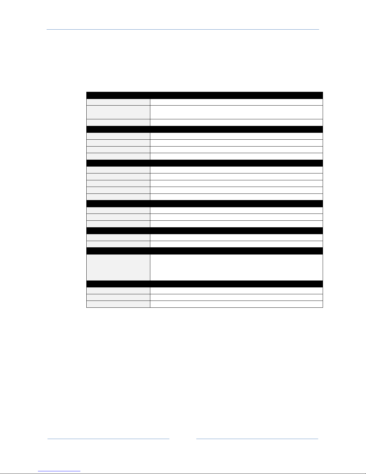
2.2. General Specification
GENERAL SPECIFICATIONS
Power supply
19.. 28 Vac (50..60 Hz), 11.. 40Vdc
maximum power
consumption
1,2 W
Isolation
1500 Vac
ETHERNET
Ethernet
10 - 100 Mbit/s
Protocol
Modbus TCP-IP
Max connection length
100 m
Connection
RJ 45 on frontal
RS485 COMMUNICATION PORTS
Number
2
Port #1
IDC10 connector (Modbus RTU Master or slave port)
Port #2
Screw terminals 10-11-12 (Modbus RTU Master or slave port)
Baudrate
1200..115200 configurable
Baudrate
1200..115200 configurable
ENVIRONMENTAL CONDITIONS
Temperature
-20 °C.. +50 °C
Humidity
30 ..90% a 40 °C no condensing
Storage temperature
-25..+85 °C
BOX
Dimensions
100 x 17,5 x 111 mm
Box; protection degree
Black, PA6, IP20
CONNECTORS
IDC 10 for Seneca bus
Removable terminals, pitch 5,08 mm
Micro USB
Ethernet RJ45
STANDARDS
EN 61000-6-4/ 2007
Emission, industrial environmental
EN 61000-6-2/ 2005
Immunity, industrial environmental
EN 61010-1/ 2001
Safety
Page 11
USER MANUAL – Z-KEY
11
3. Electrical Connections
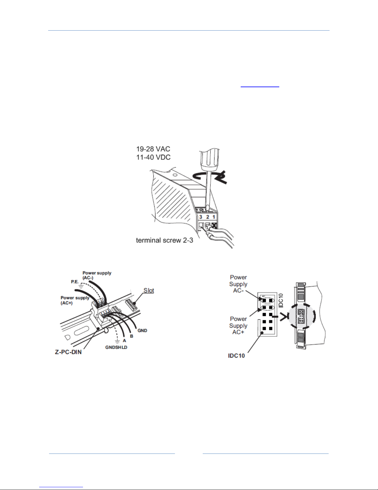
For more info please refer to the Installation manual, downloadable from www.seneca.it in the Z-KEY
section.
3.1. Terminal Positions
For power ON Z-KEY, connect the screw terminal 2-3 or use the Seneca BUS for connect the IDC10
connector:
The RS485#1 is available from the IDC10 connector
The RS485/RS232 port #2 is available from the screw terminals 10-11-12:
Page 12
USER MANUAL – Z-KEY
12
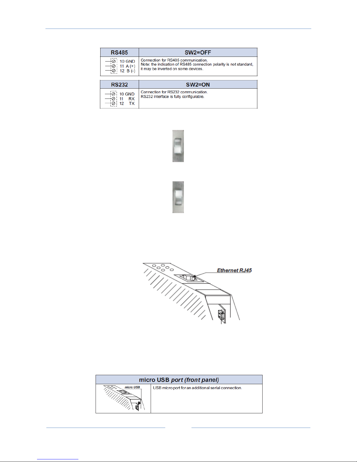
For configure port 2 in RS485 mode set the SW2 to OFF:
For configure port 2 in RS232 mode set the SW2 to ON:
Note: before to insert the cable into RJ45 connector, remove the protection rubber:
Micro USB port for a PC connection:
Page 13
USER MANUAL – Z-KEY
13
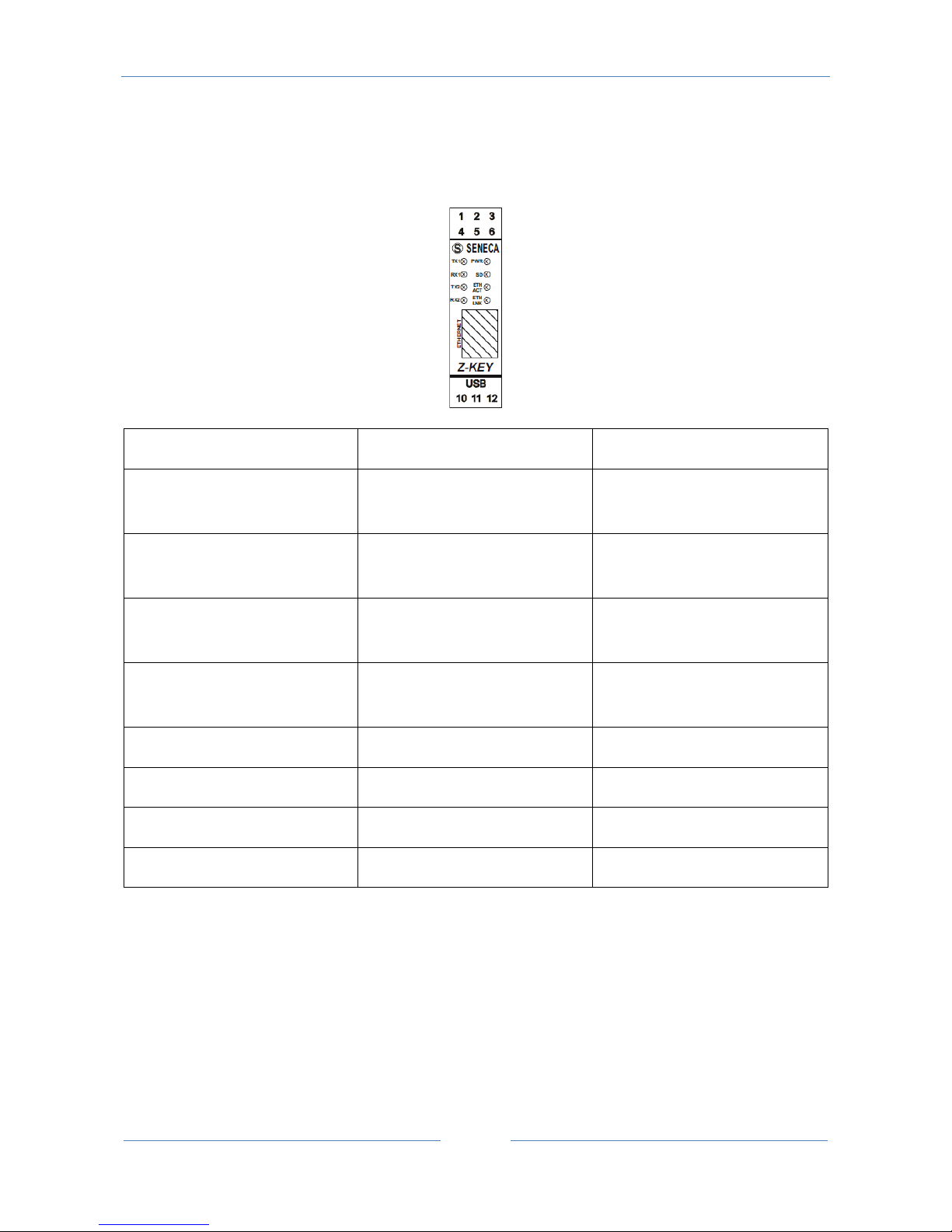
4. Debug Leds
LED
STATE
MEANING
TX1
FLASHING
Data transmission on RS485
port #1
RX1
FLASHING
Data reception on RS485 port
#1
TX2
FLASHING
Data transmission on
RS485/RS232 port #2
RX2
FLASHING
Data reception on
RS485/RS485 port #2
PWR
ON
Z-KEY is POWERED ON
SD
FLASHING
ACCESSING TO THE SD CARD
ETH TRF
FLASHING
Data traffic on Ethernet port
ETH LINK
ON
Ethernet port connected
Page 14
USER MANUAL – Z-KEY
14
5. Default Conmfiguration
The default configuration is:
IP STATIC: 192.168.90.101
Gateway: 192.168.90.1
Mode: Modbus RTU Bridge on port 1 and port 2
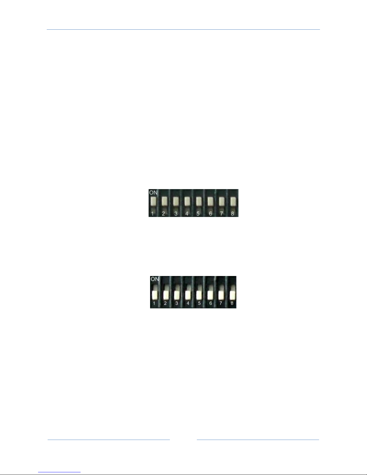
For return to the default configuration:
1) Switch off Z-KEY
2) Move to “ON” all the dip switched:
3) Switch ON Z-KEY
4) Wait 10 seconds
5) Switch OFF Z-KEY
6) Switch OFF all the dip switches:
Now Z-KEY is loaded with the default configuration.
Page 15

USER MANUAL – Z-KEY
15
6. Ethernet communication
The Z-KEY include a fast Ethernet port (10-100Mbit), the TCP-IP integrated protocol supports:
-Static IP address or DHCP
-Gateway support
-Modbus TCP-IP server protocol (support up to 8 Modbus TCP-IP client at the same time)
-Webserver (with user / password protection)
-FTP server (with user / password protection)
The default configuration for the Ethernet port is:
Static IP address 192.168.90.101
Gateway 192.168.90.1
WARNING!
BEFORE CONNECT Z-KEY ON THE NETWORK BE SURE THAT THE IP ADDRESS 192.168.90.101 IT’S NOT
USED BY ANOTHER ETHERNET DEVICE!
WARNING!
DON’T CONNECT MORE THAN 1 Z-KEY WITH THE DEFAULT IP ADDRESS ON THE NETWORK!
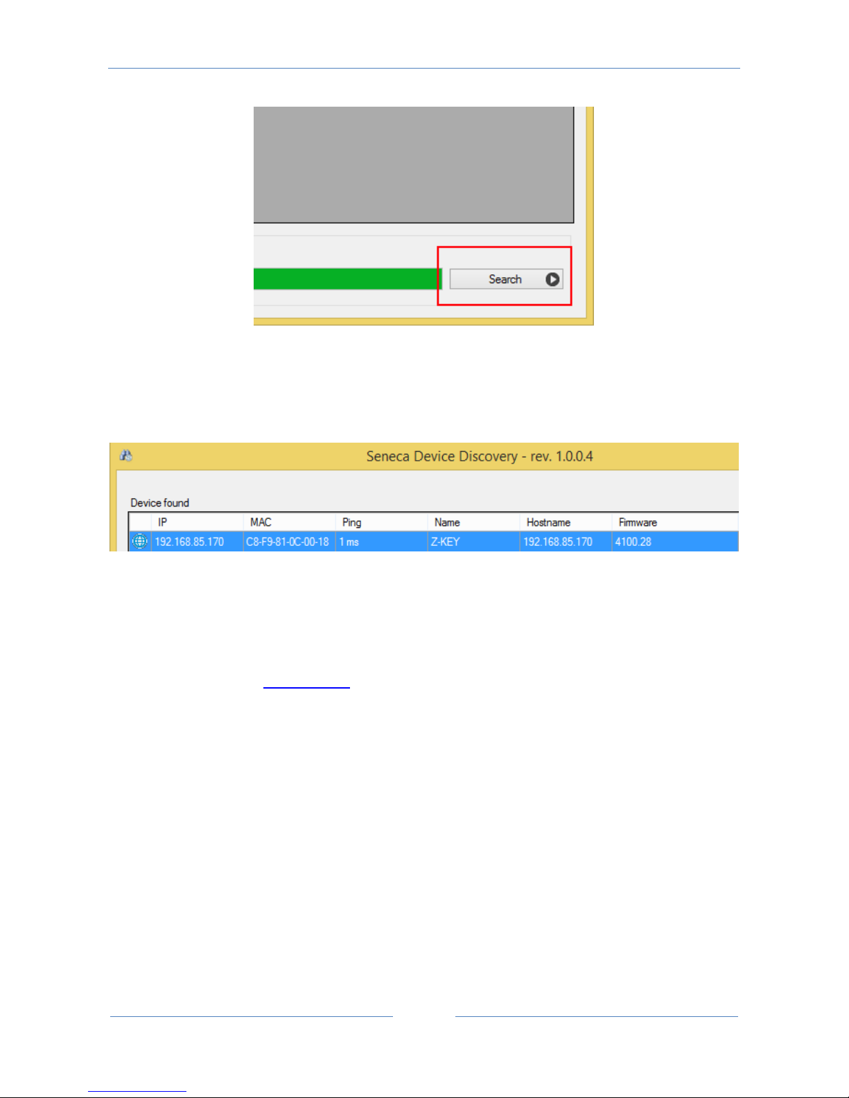
6.1. Searching Z-KEY devices in a network with the Seneca Discovery Utility
From the seneca website (www.seneca.it) in the Z-KEY section you can freely download the Seneca
Discovery Utility for obtain the actual Z-KEYs ip addresses in your network.
Click on Search for start the discovery process:
Page 16
USER MANUAL – Z-KEY
16
A list of devices found will be displayed:
6.2. Changing the IP address from the USB port
From the seneca website (www.seneca.it) in the Z-KEY section you can freely download the Seneca Easy
Setup software.
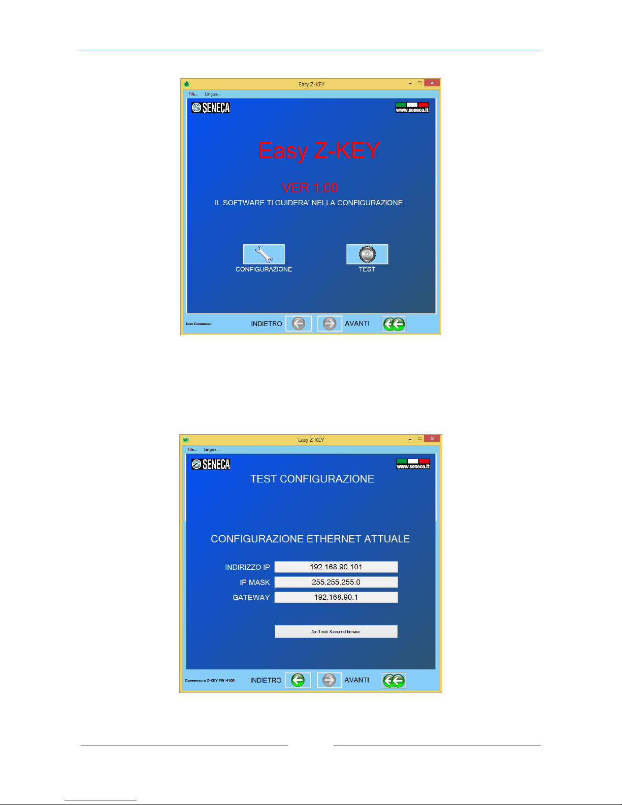
The Z-KEY section launch the EASY Z-KEY Utility for changing or obtaining the Z-KEY actual IP:
Page 17
USER MANUAL – Z-KEY
17
Connect Z-KEY to a PC with a standard micro USB cable, power up the Z-KEY and Click on “TEST” to obtain
the actual IP address:
Page 18
USER MANUAL – Z-KEY
18
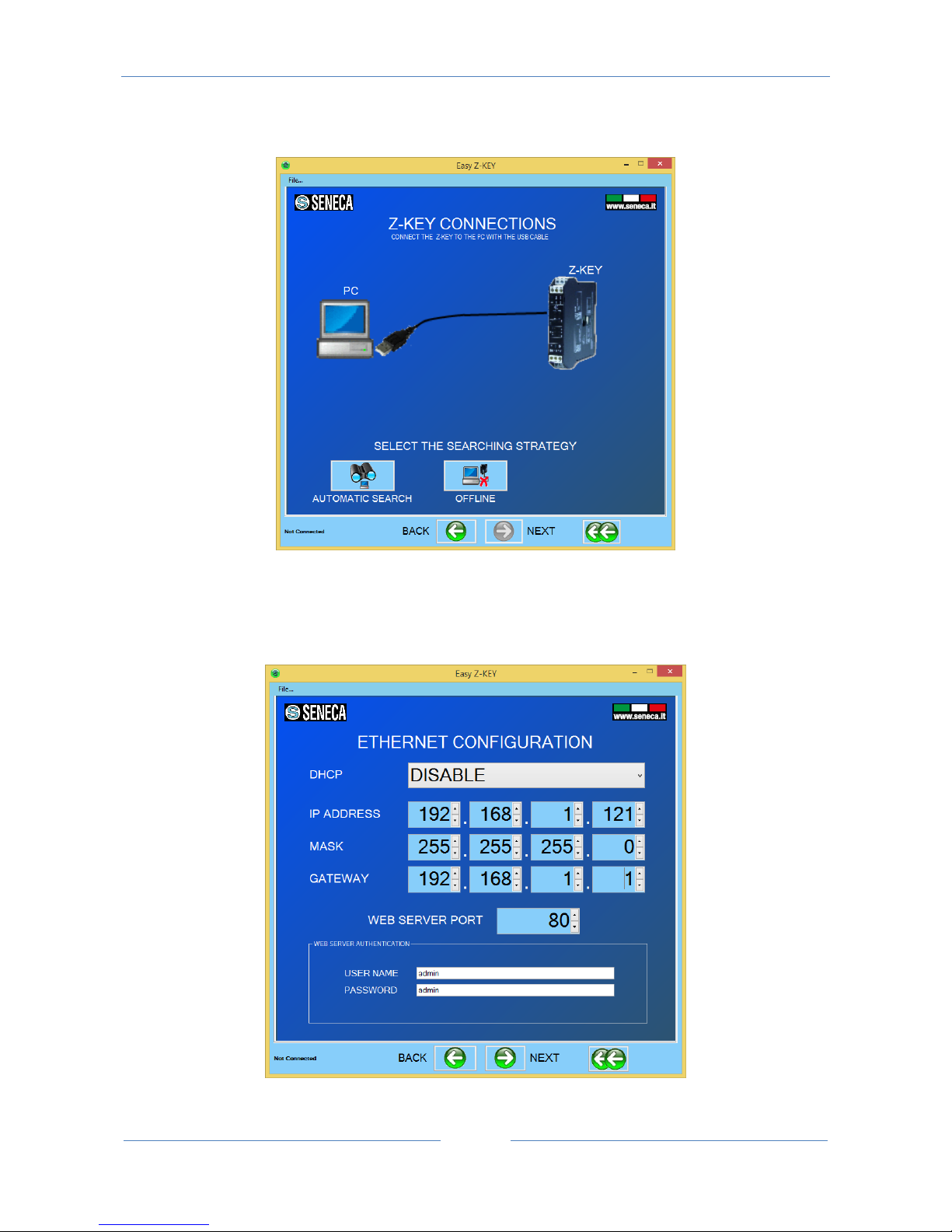
For changing the actual IP configuration return to the home page and click on “CONFIGURATION”:
Than click on “Automatic Search”, read the configuration from the Z-KEY than modify the actual
configuration with the new parameters:
Page 19
USER MANUAL – Z-KEY
19
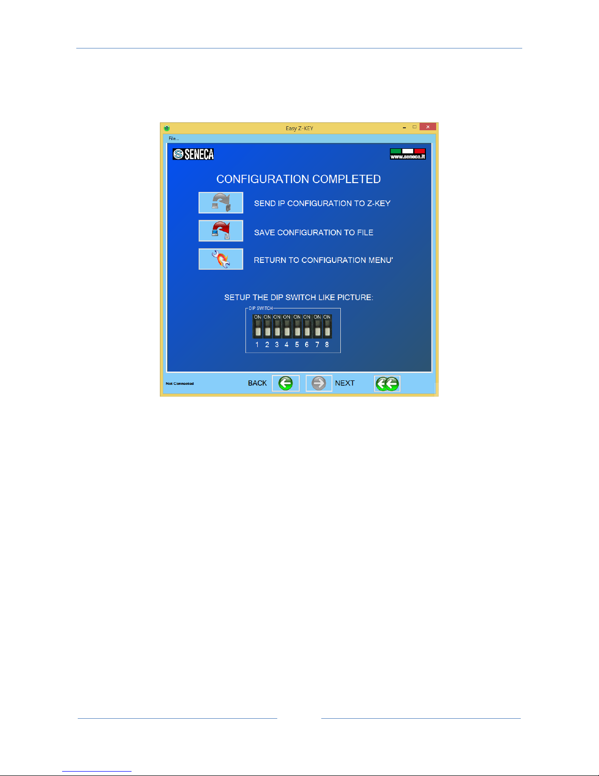
Then click on “send configuration to Z-KEY” button:
Page 20
USER MANUAL – Z-KEY
20
7. The embedded Webserver
The Z-KEY include a Webserver for setup or for view the real time TAGs value.
For Access to the internal webserver type in a browser:
http://192.168.90.101/maintenance/index.html
where 192.168.90.101 is the default ip address.
The webserver can be protected by a user name and a password.
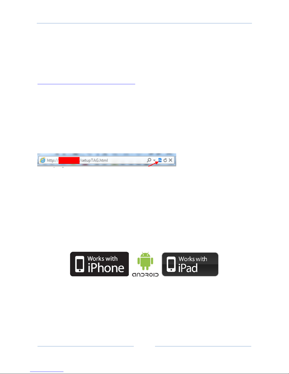
If you are using Internet explorer 9 (or newer) you must enable the compatibility mode (see the arrow
below):
The Z-KEY Embedded Webserver works with the following browser:
-Internet explorer
-Firefox
-Chrome
-Android
-Iphone/Ipad
7.1. LAN connection to the webserver
For connect an Ethernet device to the Z-KEY Webserver you must have the two Ip addresses compatible.
Page 21
USER MANUAL – Z-KEY
21
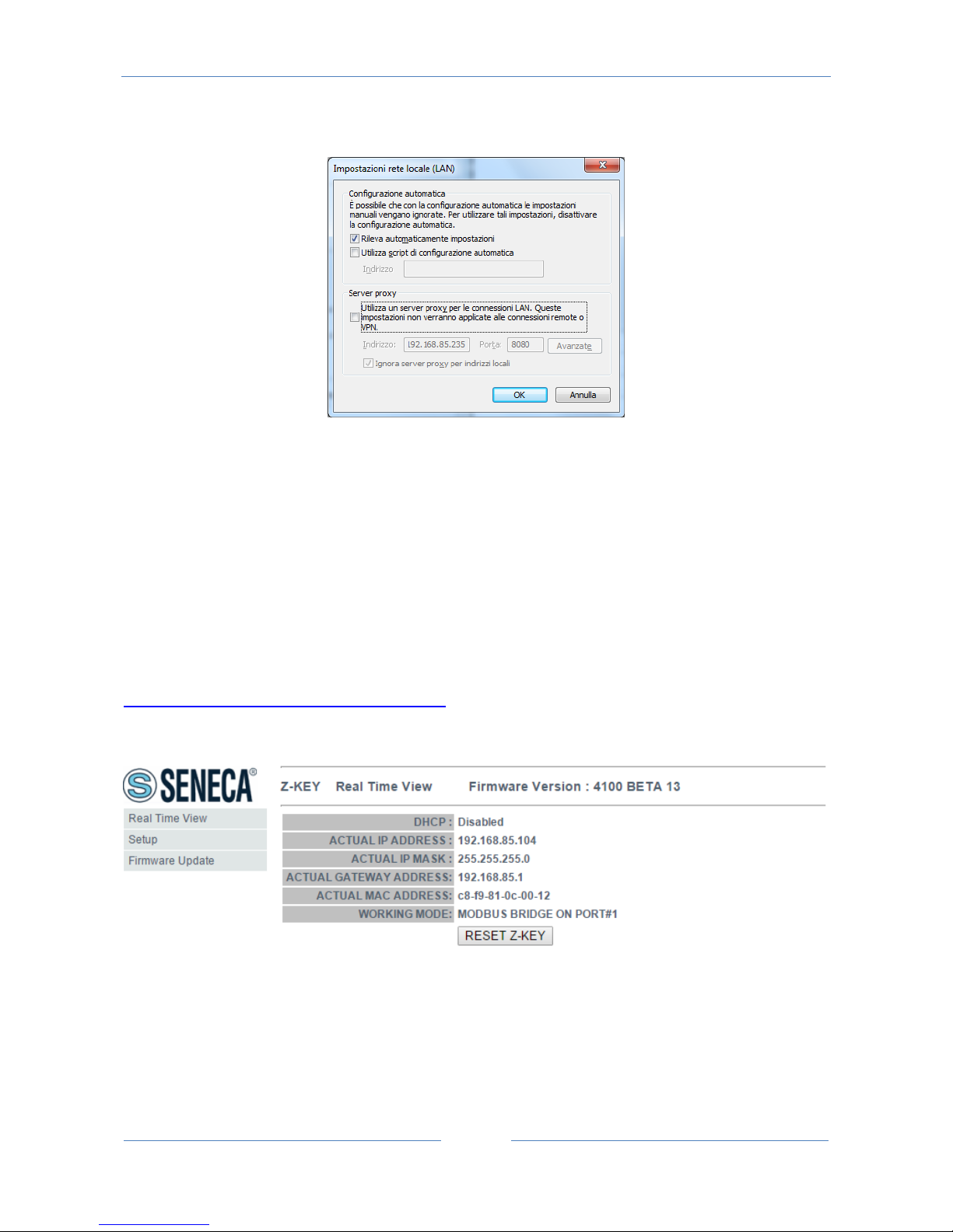
Also you must disable the flag on the proxy server configuration into the browser:
For example if the Z-KEY address is 192.168.90.101 with subnet mask 255.255.255.0 the other device must
have the ip starting with 192.168.90, so for example 192.168.90.102 can works.
The Z-KEY ethernet device support the auto-switching mode so it’s possible to connect an Ethernet device
point to point without the need of a Router or Switch.
For connect a WiFi device to the Z-KEY Webserver you need a Wifi access point or a WiFi router, in the case
of a WiFi Router into the Z-KEY configuration set the Gateway IP equals to the Router IP.
If the ip configuration it’s made correctly the webserver appear:
http://192.168.90.101/maintenance/index.html
Page 22

USER MANUAL – Z-KEY
22
8. Modbus RTU and Modbus TCP-IP protocol
The Modbus protocols supported by the Z-KEY are:
Modbus RTU Master
Modbus RTU Slave
Modbus TCP-IP Server
for more information about this protocols please refer to Modbus specification website:
http://www.modbus.org/specs.php
For using the USB Port you must install the USB driver first (see chapter 18)
8.1. Modbus function code supported
The following Modbus functions are supported:
Read Coils (function 1)
Read Discrete Inputs (function 2)
Read Holding Register (function 3)
Read Input Registers (function 4)
Write Single Coil (function 5)
Write Single Register (function 6)
Write Multiple registers (function 16)
Page 23
USER MANUAL – Z-KEY
23
9. Bridge Modbus TCP-IP to Modbus RTU
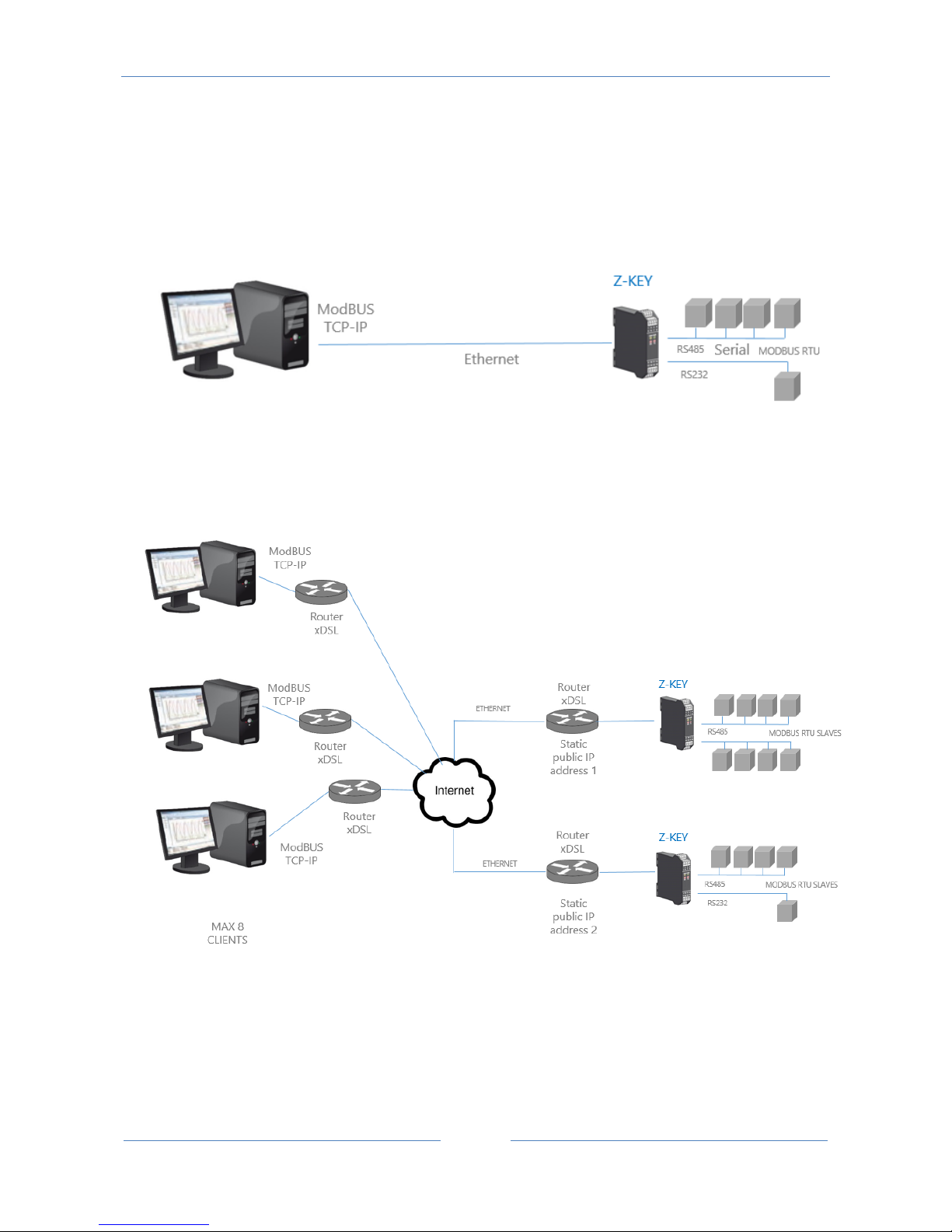
In this scenario a Modbus TCP-IP master is connected with ethernet to Z-KEY, one or more Modbus RTU slaves (for
example the Z-PC Seneca Series) are connected to the RS232/RS485 serial ports.
A typical LAN connection is represented into this figure:
Also a remote communication through internet with multiple clients is possible:
For internet communication the Routers connected to the Z-KEY must have a static ip address (or a DDNS service
activated).
A Maximum of 8 simultaneous Modbus TCP-IP clients is supported.
Page 24
USER MANUAL – Z-KEY
24
9.1. How it works
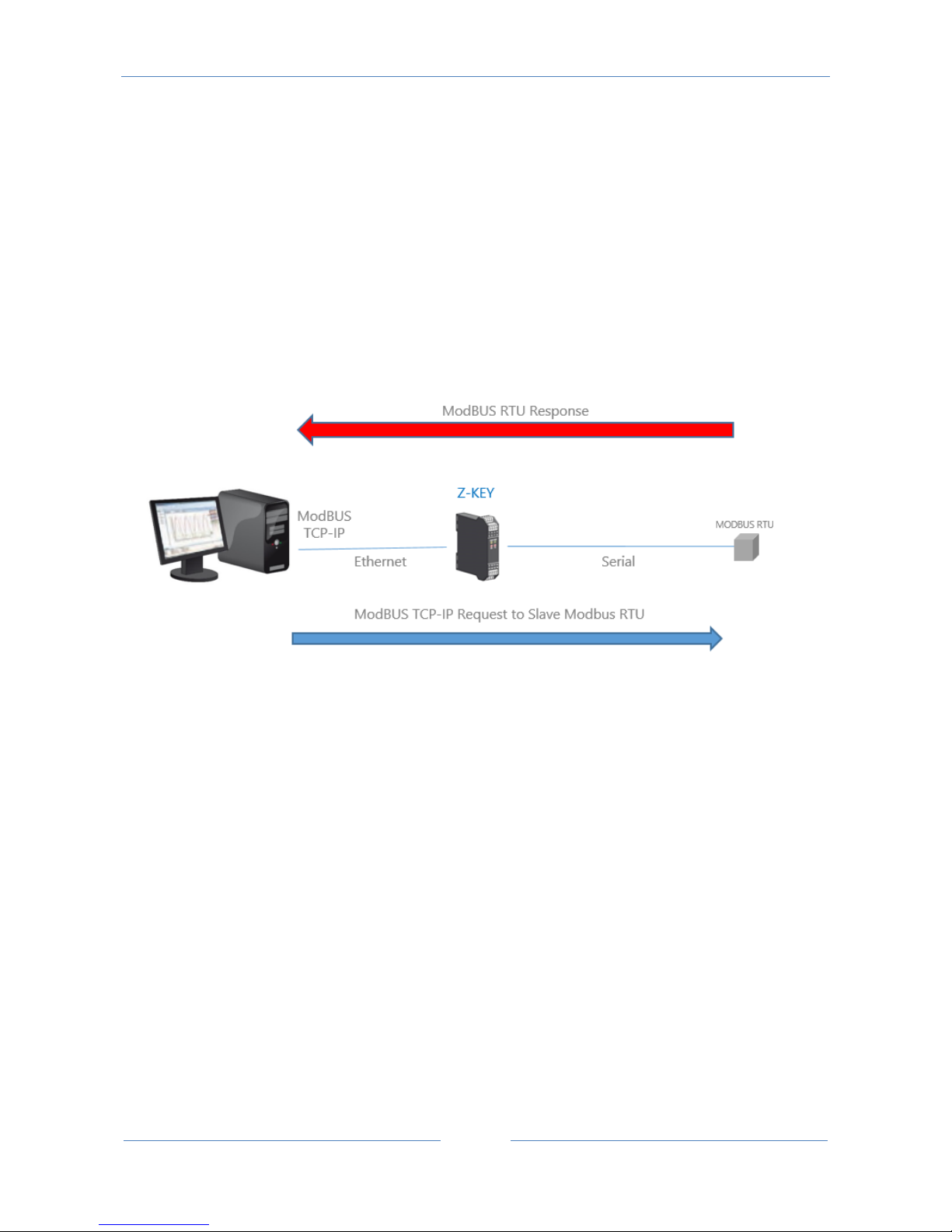
The Bridge Modbus TCP-IP to Modbus RTU is the simplest way to communicate with Modbus RTU slaves by
an ethernet connection.
There is no need to configure which registers must be requested because the conversion from Ethernet to
serial is executed in real time.
Only the serial configuration must be made (baud rate, parity etc…).
The Master (client) Modbus TCP-IP request a modbus register by ethernet, then the Z-KEY convert the
request to the serial Modbus RTU slave, the Modbus RTU response is also retranslated in Modbus TCP to
the Master.
CAUTION!
It’s not possible to connect two Modbus RTU slaves with the same Modbus address, if you need to connect 2
Modbus RTU slaves with the same Modbus address (not configurable) you must use 2 Z-KEYs.
9.2. Modbus Bridge Webserver configuration
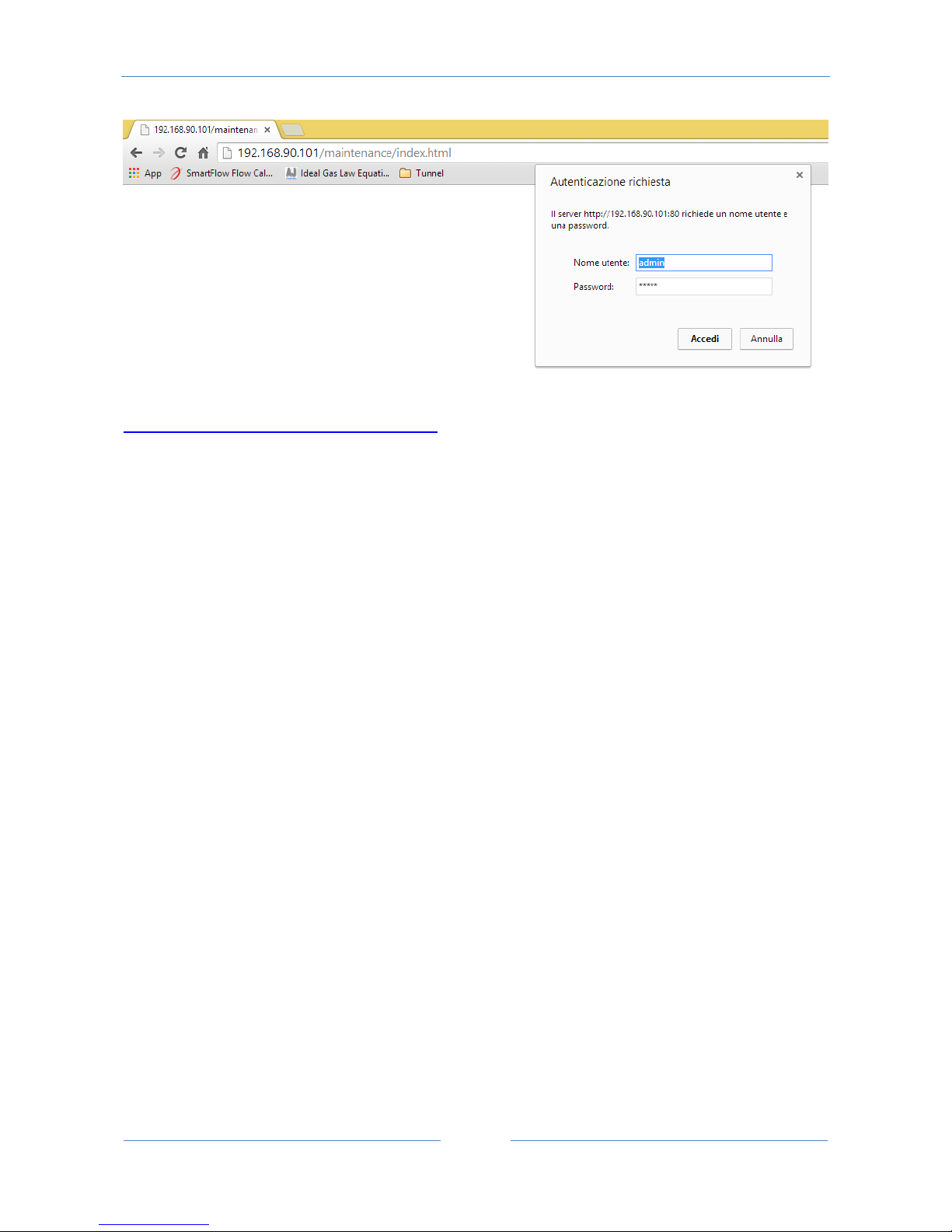
Connect to the webserver by entering the ip address, by default:
Page 25
USER MANUAL – Z-KEY
25
http://192.168.90.101/maintenance/index.html
Enter the user name and password, by default:
User: admin
Password: admin
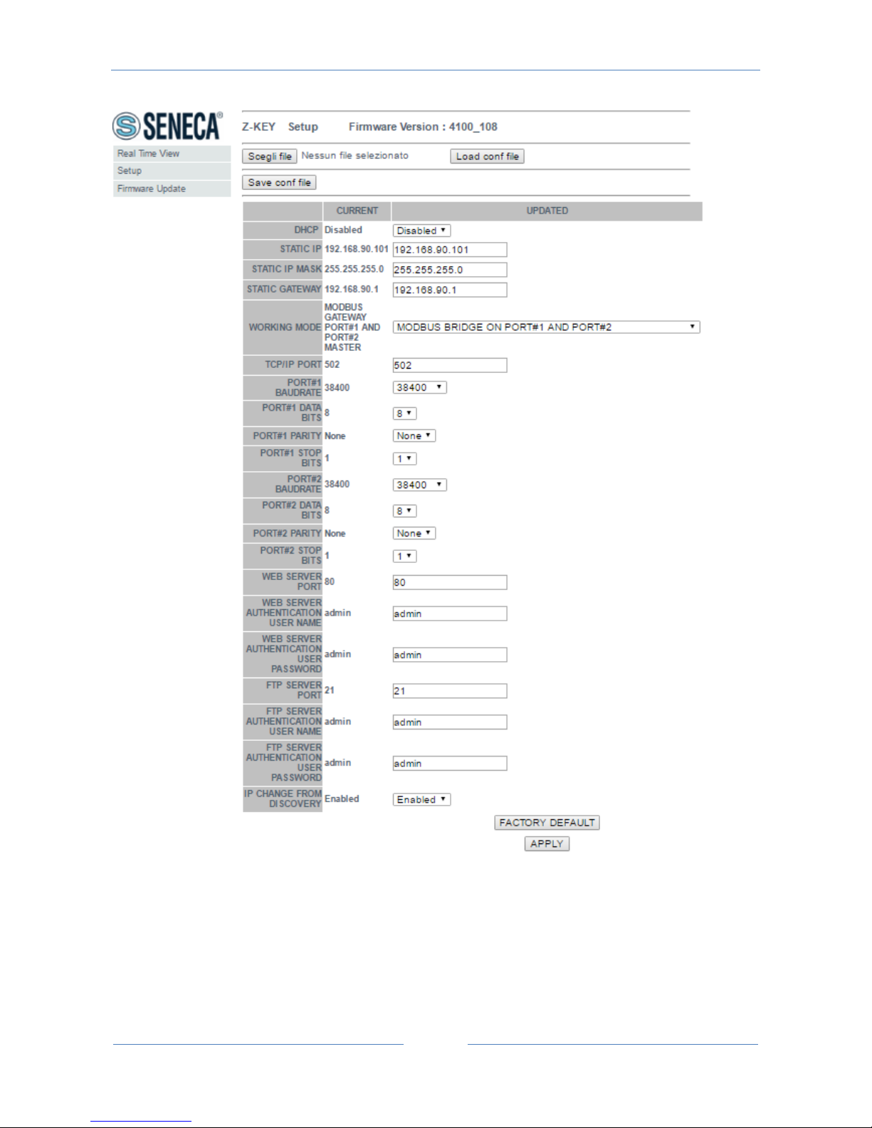
Now the Webserver can be used for configuring the Z-KEY module, all parameters are visible clicking on
“Setup” button to the left of the screen:
Page 26
USER MANUAL – Z-KEY
26
On the first column represents the parameter name, the second column (current) it’s the current
parameter value. The last column can be used for changing the current configuration.
When a configuration it’s made you must confirm with “APPLY”, then the new configuration became
operative.
If you need to reset to the default parameters click on “FACTORY DEFAULT” button.
Page 27

USER MANUAL – Z-KEY
27
The parameters are explained below:
DHCP
Disable: A static Ip address is used
Enable: The IP address, the IP-Mask and the Gateway address are obtained from the DHCP server.
The Z-KEY IP address can be read from the USB port with the Easy Setup test configuration , or with the
Seneca Discovery utility (see the Z-KEY section on seneca web site for download).
STATIC IP ADDRESS
Static IP address when DHCP is Disable
STATIC IP MASK
mask when DHCP is Disable
STATIC GATEWAY
Gateway address when DHCP is Disable
WORKING MODE
Select the Modbus Bridge working mode, for Modbus Bridge you can select which serial port use.
Modbus Bridge on port#1: the packets are routed only to serial port 1 (no packets are routed to serial port
2)
Modbus Bridge on port#2: the packets are routed only to serial port 2 (no packets are routed to serial port
1)
Modbus Bridge on port#1 and port#2: the packets are routed to serial port1 and serial port2 (Note that in
this case all the slaves modbus addresses must be different!)
TCP/IP PORT
TCP-IP port for Modbus TCP-IP Server protocol (Max 8 clients)
Page 28

USER MANUAL – Z-KEY
28
PORT #n BAUDRATE
Used to Set the port baudrate
PORT #n BITS
Used to Set the number of bits for the serial communication.
PORT #n PARITY
Used to Set the port parity (None, Odd or even)
PORT #n STOP BITS
Used to Set the port parity (1 or 2; note that if the parity is set, only 1 bit can be used)
PORT #n TIMEOUT
Used to Set the timeout on Modbus Master mode before making a new call
WEB SERVER PORT
Used to Set the TCP-IP port for the Webserver
WEB SERVER AUTHENTICATION USER NAME
Used to Set the User Name for accessing the Webserver (if User Name and Password are leave empty no
authentication is require for webserver access)
WEB SERVER AUTHENTICATION USER PASSWORD
Used to Set the Password for accessing the Webserver (if User Name and Password are leave empty no
authentication is require for webserver access)
FTP SERVER PORT
Used to Set the TCP-IP port for the FTP Server
Page 29

USER MANUAL – Z-KEY
29
FTP SERVER AUTHENTICATION USER NAME
Used to Set the User Name for accessing the FTP Server (if User Name and Password are leave empty no
authentication is require for webserver access)
FTP SERVER AUTHENTICATION USER PASSWORD
Used to Set the Password for accessing the FTP server (if User Name and Password are leave empty no
authentication is require for ftp access)
IP CHANGE FROM DISCOVERY
Used to Set if a user is allowed to change IP configuration from the software “Seneca Discovery Device”
WARNING!
REMEMBER ALWAYS TO CONFIGURE THE WEBSERVER AND FTP AUTHENTICATION USER NAME AND
PASSWORD FOR RESTRICT THE ACCESS TO THE FTP AND THE WEBSERVER. IF YOU LEAVE THE TWO
PARAMETERS TEXT BOXES BLANK NO AUTHENTICATION IT’S REQUIRED FOR ACCESS.
WARNING!
WHEN USE THE MODBUS BRIDGE MODE, REMEMBER THAT ALL THE MODBUS SLAVES MUST HAVE A
DIFFERENT ADDRESS!
CAUTION!
If you are using Internet explorer 9 (or newer) you must enable the compatibility mode (see the arrow
below):
Page 30
USER MANUAL – Z-KEY
30
10. Gateway Modbus TCP-IP / Modbus RTU (Port 1 and Port 2 Modbus
Master)
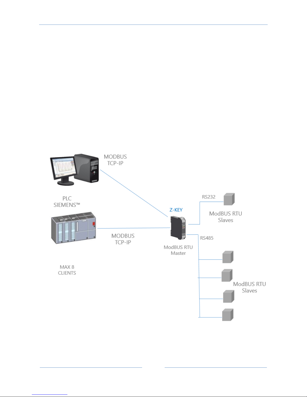
In this scenario a Modbus TCP-IP master is connected with ethernet to Z-KEY, one or more Modbus RTU
slaves (for example the Z-PC Seneca Series) are connected to the RS232/RS485 serial ports.
The Z-Key configured in Gateway is used for optimizing the Network performance and Modbus TCP-IP PLC
software. Also PLCs like Siemens™ can be connected with Modbus RTU slaves by using the free standard
Modbus TCP-IP library without the need of a customization.
A typical LAN connection is represented into this figure:
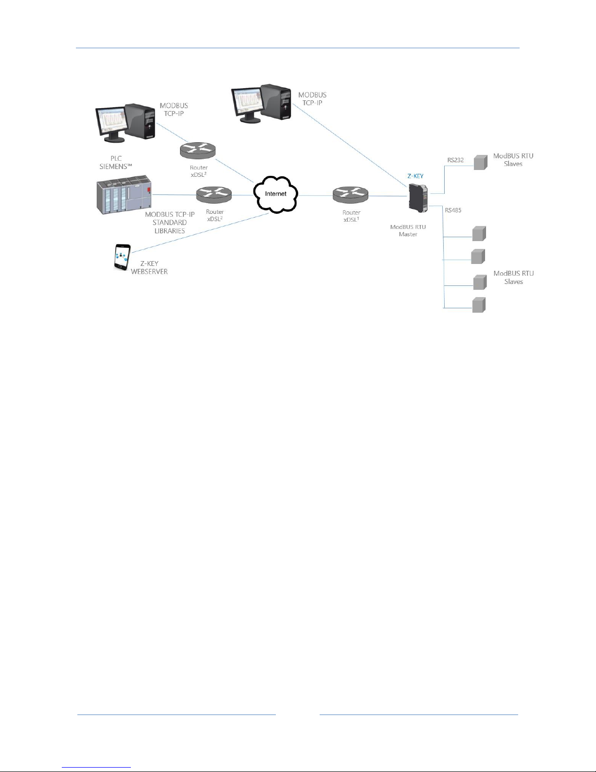
Also a remote communication through internet with multiple clients is possible, with the gateway
configuration the tags are visible through the internal webserver:
Page 31
USER MANUAL – Z-KEY
31
For internet communication the Routers connected to the Z-KEY must have a static ip address (or a DDNS
service activated).
A Maximum of 8 simultaneous Modbus TCP-IP clients is supported.
10.1. How it works
Into a Modbus RTU bus it’s essential to read as fast as possible the registers from the various Modbus Slave
devices.
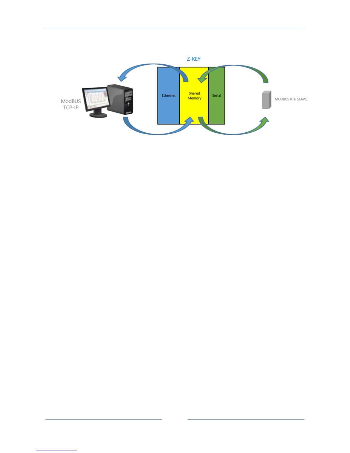
The Z-KEY can be configured with up to 500 tag (1 tag = 1 variable that can be composed by one or two
Modbus registers), these values are stored into the Z-KEY shared memory that can be accessed from
Ethernet.
The Shared Memory is refreshed as fast as possible by the serial communication, so when a register is
required from the Ethernet port, the values are read directly from the Shared memory without the needed
of waiting the Slave response time:
Page 32
USER MANUAL – Z-KEY
32
Another benefit is that the Shared memory can be accessed also from the web using the Z-KEY embedded
webserver.
Multiple Slaves can also be converted into a unique Modbus address, this makes much easier to develop
software from the ethernet side.
PLCs can also benefit the access to a unique slave address for use with the standard Modbus TCP-IP
libraries (linked to a unique modbus address).
A unique slave address is needful when there is a big slaves number, in this case using Z-KEY in gateway
mode will reduce drastically the bus polling time and the number of slaves can grow using more than one ZKEY.
From the revision firmware 4100_108 the gateway can automatically optimize the Modbus request by
using a multiple register request. With this optimization the bus speed increases drastically.
10.2. Modbus Gateway configuration (Port 1 and Port 2 Modus Master)
Connect to the webserver by entering the ip address, by default:
Page 33
USER MANUAL – Z-KEY
33
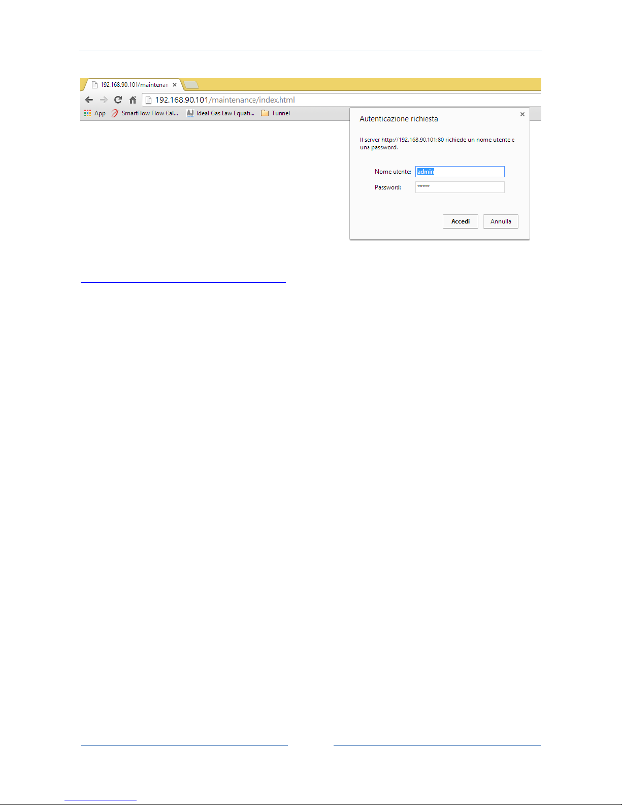
http://192.168.90.101/maintenance/index.html
Enter the user name and password, by default:
User: admin
Password: admin
Now the Webserver can be used for configuring the Z-KEY module, all parameters are visible clicking on
“Setup” button to the left of the screen:
Page 34
USER MANUAL – Z-KEY
34
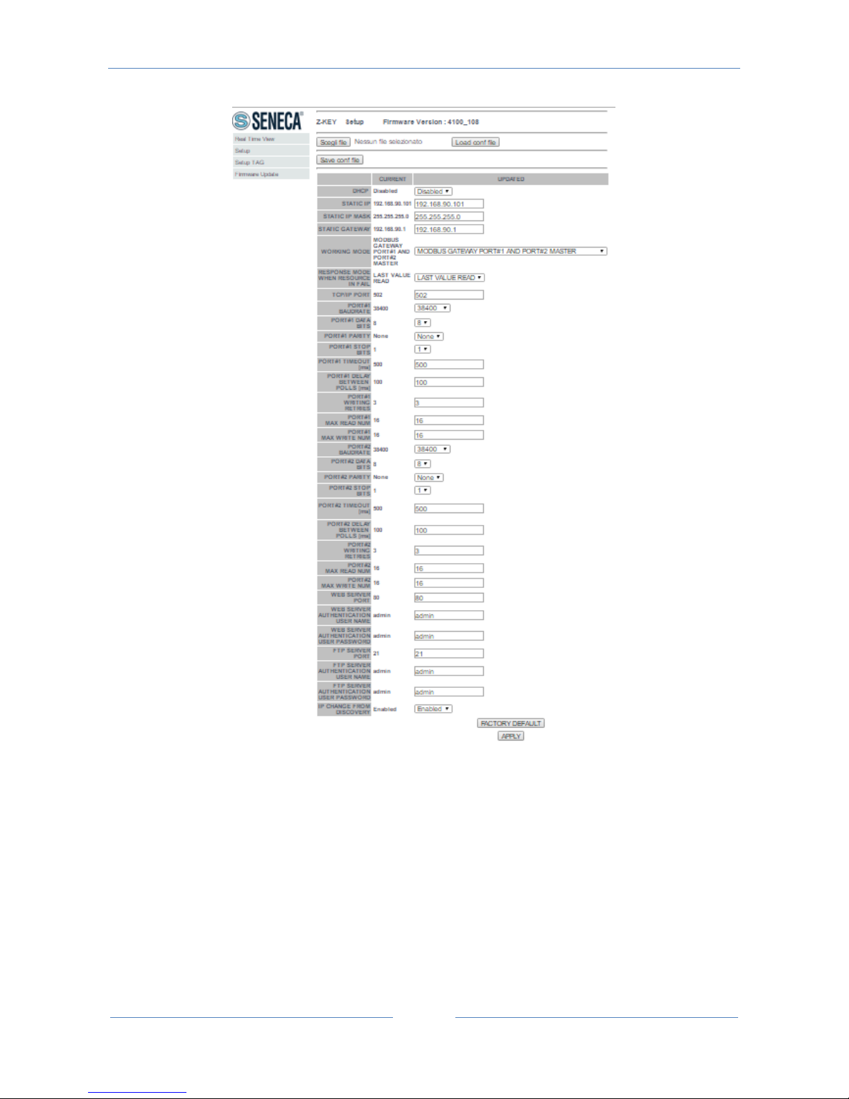
On the first column represents the parameter name, the second column (current) it’s the current
parameter value. The last column can be used for changing the current configuration.
When a configuration it’s made you must confirm with “APPLY”, then the new configuration became
operative.
If you need to reset to the default parameters click on “FACTORY DEFAULT” button.
In this page you can save and load a previous configuration (a configuration is made of Configuration and
Tags configuration).
The parameters are explained below:
Page 35

USER MANUAL – Z-KEY
35
DHCP
Disable: A static Ip address is used
Enable: The IP address, the IP-Mask and the Gateway address are obtained from the DHCP server.
The Z-KEY IP address can be read from the USB port with the Easy Setup test configuration, or with the
Seneca Discovery utility (see the Z-KEY section on seneca web site for download).
STATIC IP ADDRESS
Static IP address when DHCP is Disable
STATIC IP MASK
mask when DHCP is Disable
STATIC GATEWAY
Gateway address when DHCP is Disable
WORKING MODE
Select the Modbus Gateway port1 and port2 Master working mode.
RESPONSE MODE
Select which type of response do you want when a Modbus slave don’t respond to a modbus request. You
can select from
Last value read (the value is frizeed to the last value read)
Exception (Z-KEY exception response)
TCP/IP PORT
TCP-IP port for Modbus TCP-IP Server protocol (Max 8 clients)
Page 36

USER MANUAL – Z-KEY
36
PORT #n BAUDRATE
Used to Set the port baudrate
PORT #n BITS
Used to Set the number of bits for the serial communication.
PORT #n PARITY
Used to Set the port parity (None, Odd or even)
PORT #n STOP BITS
Used to Set the port parity (1 or 2; note that if the parity is set, only 1 bit can be used)
PORT #n TIMEOUT
Used to Set the timeout on Modbus Master mode before making a new call
PORT #n DELAY BETWEEN POLLS
Used to Set the delay between two Modbus Master request
PORT #n WRITING RETRIES
Used to Set the retries to write a Modbus register into the Modbus Master mode
PORT #n MAX WRITE NUM
Used to Set the maximum number of registers that can be written with the Modbus function “Write Multiple
Registers” or “Write Multiple Coils”.
PORT #n MAX READ NUM
Used to Set the maximum number of registers that can be read with the Modbus function “Read Multiple
Registers” or “Read Multiple Coils”.
Page 37

USER MANUAL – Z-KEY
37
WEB SERVER PORT
Used to Set the TCP-IP port for the Webserver
WEB SERVER AUTHENTICATION USER NAME
Used to Set the User Name for accessing the Webserver (if User Name and Password are leave empty no
authentication is require for webserver access)
WEB SERVER AUTHENTICATION USER PASSWORD
Used to Set the Password for accessing the Webserver (if User Name and Password are leave empty no
authentication is require for webserver access)
FTP SERVER PORT
Used to Set the TCP-IP port for the FTP Server
FTP SERVER AUTHENTICATION USER NAME
Used to Set the User Name for accessing the FTP Server (if User Name and Password are leave empty no
authentication is require for webserver access)
FTP SERVER AUTHENTICATION USER PASSWORD
Used to Set the Password for accessing the FTP server (if User Name and Password are leave empty no
authentication is require for ftp access)
IP CHANGE FROM DISCOVERY
Used to Set if a user is allowed to change IP configuration from the software “Seneca Discovery Device”
WARNING!
Page 38
USER MANUAL – Z-KEY
38
REMEMBER ALWAYS TO CONFIGURE THE WEBSERVER AND FTP AUTHENTICATION USER NAME AND
PASSWORD FOR RESTRICT THE ACCESS TO THE FTP AND THE WEBSERVER. IF YOU LEAVE THE TWO
PARAMETERS TEXT BOXES BLANK NO AUTHENTICATION IT’S REQUIRED FOR ACCESS.
CAUTION!
If you are using Internet explorer 9 (or newer) you must enable the compatibility mode (see the arrow
below):
10.3. Modbus Gateway Tags Setup, export and import
The Z-KEY in Modbus Gateway mode needs to configure the Tags to put into the internal shared memory.
From the Webserver click on “Setup TAGs” button to the left menu:
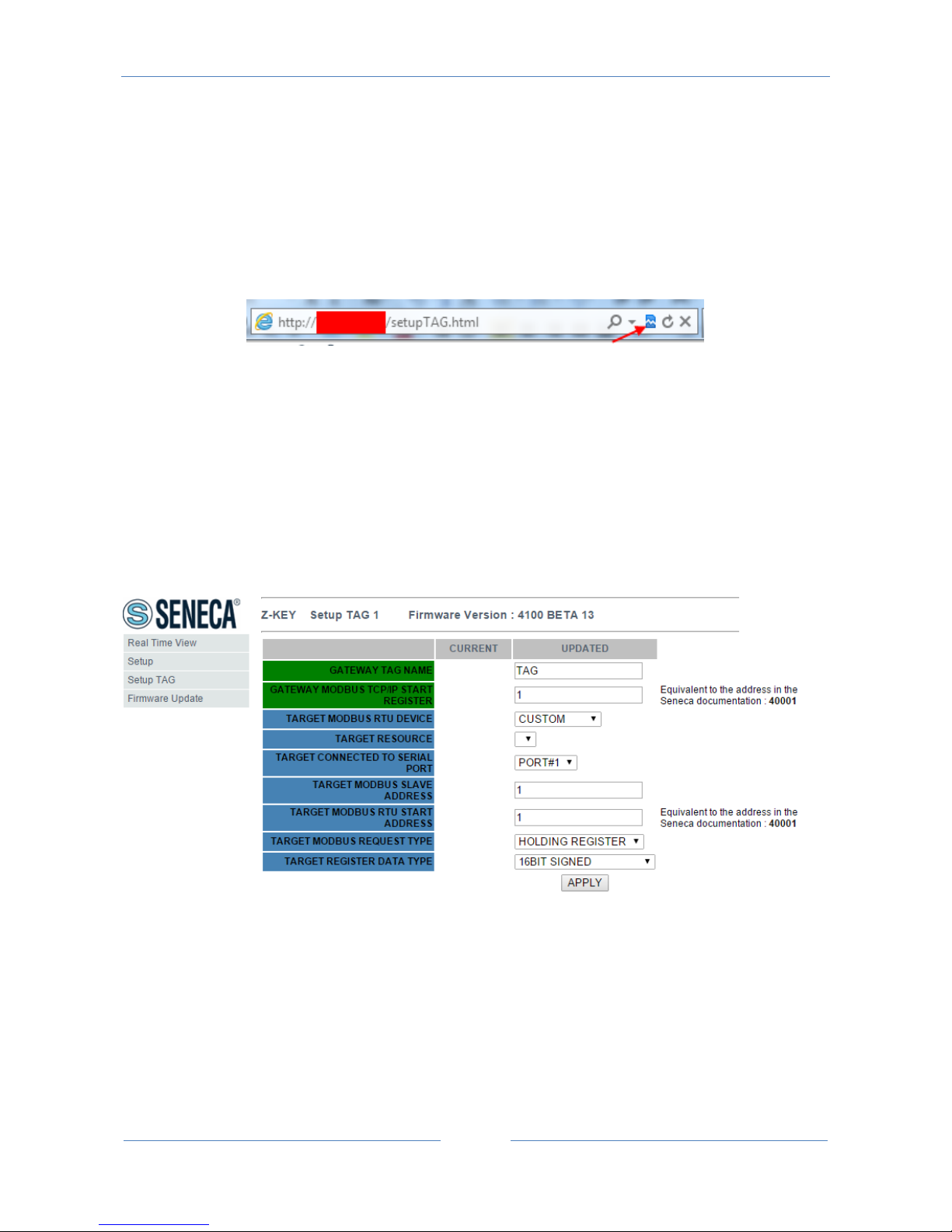
Now you can ADD, Modify, Delete or move one tag. When you modify or add a tag a new page appear:
Gateway Tag Name
Set the Tag name to show in the Webserver realtime view.
Gateway Modbus TCP-IP Start Register
Page 39

USER MANUAL – Z-KEY
39
Set the address where the tag is placed in shared memory for access from Modbus TCP-IP.
Target Modbus RTU Device
Select the Modbus RTU slave model from the Seneca database or select “custom” if you don’t use a Seneca
Modbus RTU slave.
Target Resource
If you are using a Seneca Modbus RTU Slave select the resource name from the Seneca database.
Target Connected to serial port
Select at which Z-KEY serial port is connected the modbus rtu slave device.
Target Modbus RTU Slave Station Address
Select the Device Modbus Station Address (also named Modbus node address).
Target Modbus RTU start register
Select the Modbus RTU slave start register TAG
Modbus Request Type
Select the Modbus Register Request type from:
Coil
Discrete Input
Holding Register
Input Register
Data Type
Select the TAG variable type from:
Page 40
USER MANUAL – Z-KEY
40
16 BITS UNSIGNED: 1 modbus register, from 0 to 65535
16 BITS SIGNED: 1 modbus register, from -32768 to +32767
32 BITS UNSIGNED MSW : 2 modbus registers with the lower address Modbus register that hold the Most
Significant Word, from 0 to 4294967295
32 BITS UNSIGNED LSW : 2 modbus registers with the lower address Modbus register that hold the Less
Significant Word, from 0 to 4294967295
32 BITS SIGNED MSW : 2 modbus registers with the lower address Modbus register that hold the Most
Significant Word, from -2147483648 to +2147483647
32 BITS SIGNED LSW : 2 modbus registers with the lower address Modbus register that hold the Less
Significant Word, from -2147483648 to +2147483647
FLOAT MSW : 2 modbus registers with the lower address Modbus register that hold the Most Significant
Word, Floating point single precision (IEEE 758-2008)
FLOAT LSW : 2 modbus registers with the lower address Modbus register that hold the Less Significant
Word, Floating point single precision (IEEE 758-2008)
BIT : 1 Boolean coil or Discrete input register
this field is automatically filled if you have select a Seneca Device into the “Device” field.
WARNING!
All 32 bits values are stored into 2 consecutive registers, for example:
TAG Totalizer 1 in unsigned 32 bits MSW type is stored into registers 40016 and 40017:
The most significant word is the register 40016, the less significant word is the 40017.
So the 32bits value is obtained by the following relation:
𝑇𝑜𝑡𝑎𝑙𝑖𝑧𝑒𝑟1=𝑅𝑒𝑔(40017)+(𝑅𝑒𝑔(40016)×216)=
𝑅𝑒𝑔(40017)+(𝑅𝑒𝑔(40016)×65536)
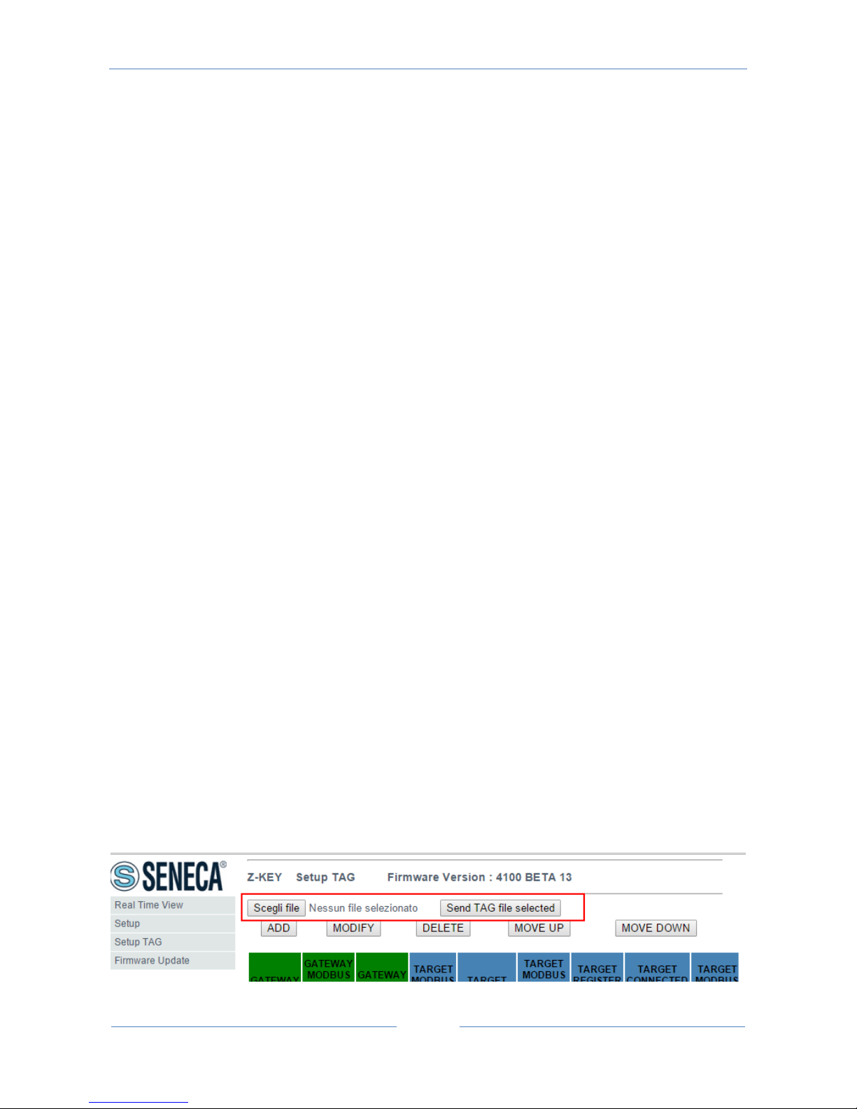
The Tags setup can be imported/exported from/to a “.cgi” file:
Page 41

USER MANUAL – Z-KEY
41
Note that a .cgi file can be also imported/exported from/to the Z-KEY Excel template.
10.4. Modbus Gateway Real Time view
Where the TAG are setup it’s possible to view in real time the communication from the webserver.
The real time view will show the TCP-IP configuration and the TAGS info.
The Tags info include: The TAG Name, the Gateway TAG Modbus Address, the Tag value and the TAG status
(OK = read ok, FAIL = read fail).
This Real Time View is very useful for connecting Mobile devices.
10.5. Using the Microsoft Excel ™ template for Tags setup
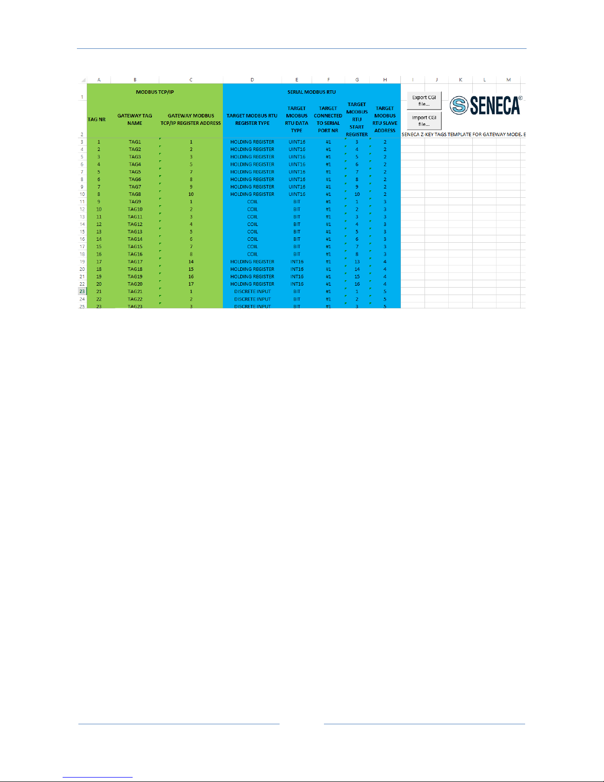
Preparing the Tag configuration can be a frustrating operation if it’s made with the webserver so a
Microsoft Excel™ Template is available for create a .bin file to import to the Z-KEY.
This operation drastically speed up the TAG configuration.
The template can be freely downloaded from the seneca website into the Z-KEY section.
Page 42
USER MANUAL – Z-KEY
42
TAG NR
The tag index from 1 to 500
Gateway Tag Name
Enter the Tag mnemonic name
Gateway Modbus TCP-IP Register Address
Enter the TAG register address that will be accessed from TCP-IP (also from serial port if slave mode is
configured). For Seneca Modbus Standard address 1 holding register is equivalent to 40001, address 2 to
40002 etc… .
Target Modus RTU REGISTER TYPE
Select the register type from the combobox list
Target Modus RTU DATA TYPE
Select the target modbus rtu register type
Target Connected to serial port NR
Select the serial port where the slave modbus is connected to
Target Modbus RTU Start Register
Enter the Modbus Slave start register (if holding register 1=40001 etc…)
Page 43

USER MANUAL – Z-KEY
43
Target Modbus RTU Slave Address
Enter the Modbus RTU Slave Station address
The setup can be exported from Excel to a .cgi file (for to be imported in the webserver) or imported from a
.cgi file (exported from the webserver).
Page 44
USER MANUAL – Z-KEY
44
11. Gateway Modbus TCP-IP / Modbus RTU (1 port Master and 1 port
Slave)
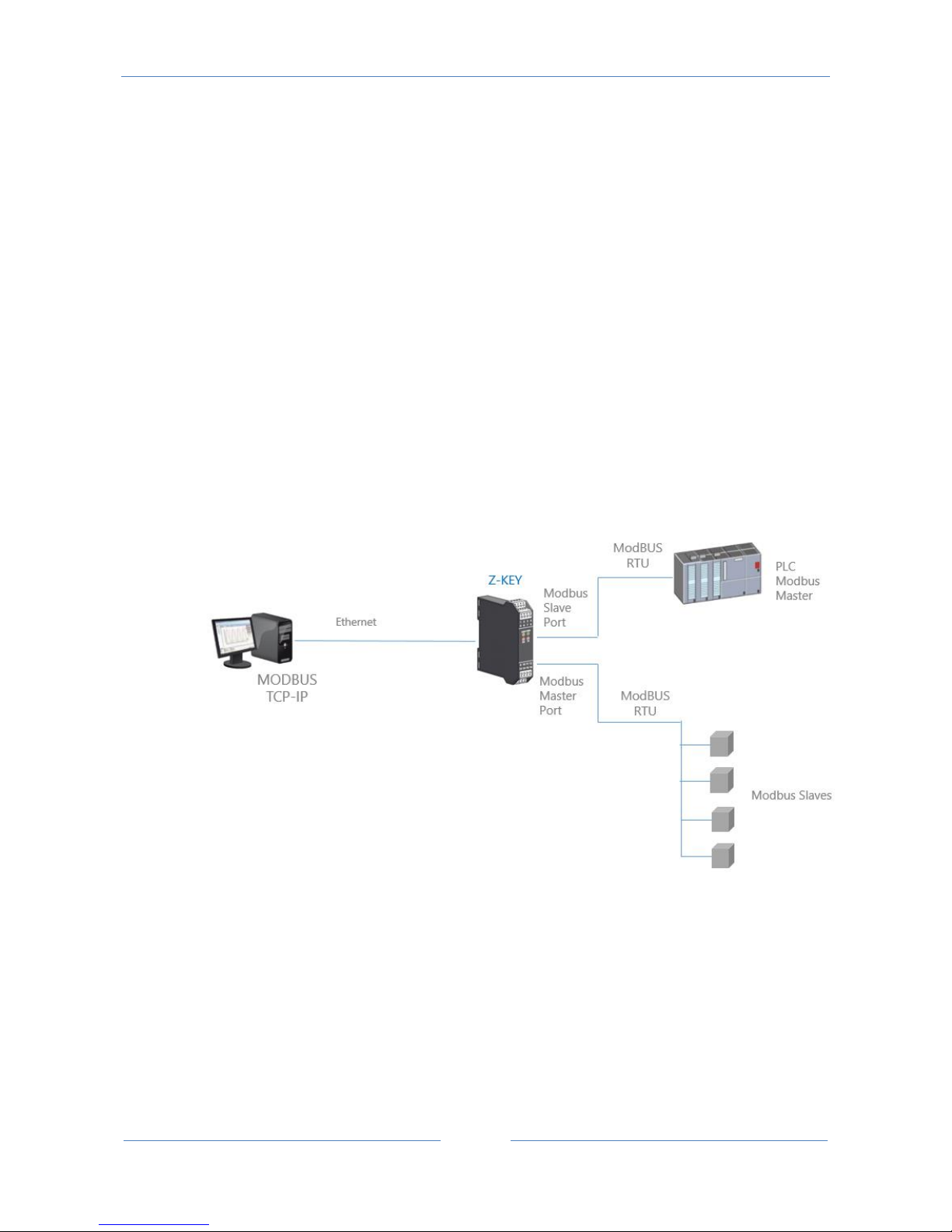
In this scenario a Modbus TCP-IP master is connected with ethernet to Z-KEY, one PLC with only the
Modbus Master protocol is connected to the Z-KEY Modbus slave port. By this port the Modbus RTU Slaves
(connected to the Z-KEY Modbus Master port) values are available for the PLC.
Also the PLC can write to the Modbus Slaves registers.
Through the ethernet the Registers written from the Z-KEY Modbus Slave Port or read from the the Modbus
Slave Port are available.
A typical LAN connection is represented into this figure:
11.1. How it works
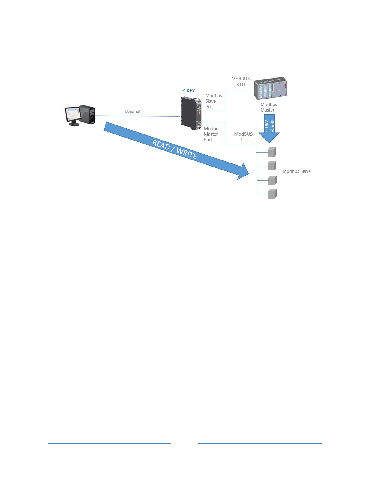
A lot of PLCs have the limitation that only the Modbus Master protocol is implemented. When values from
the Modbus Slaves must be read/write from the PLC and also from a SCADA/Datalogger, the Z-KEY can be
configured with one serial port in modbus slave (connected to the PLC modbus master port) and the other
in modbus master (connected to the modbus slaves).
Page 45
USER MANUAL – Z-KEY
45
This feature is possible using the internal Z-KEY shared memory.
The PLC Modbus Master and the Ethernet client(s) writes/reads the Z-KEY shared memory registers, the ZKEY maintain refreshed the shared memory with the Modbus Slaves.
CAUTION!
Z-KEY IN GATEWAY MODE DOESN’T IMPLEMENT THE MODBUS TCP-IP CLIENT PROTOCOLS.
11.2. Gateway Modbus TCP-IP / Modbus RTU (1 port Master and 1 port Slave)
Webserver configuration
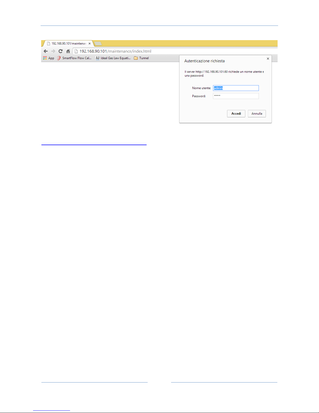
Connect to the webserver by entering the ip address, by default:
Page 46
USER MANUAL – Z-KEY
46
http://192.168.90.101/maintenance/index.html
Enter the user name and password, by default:
User: admin
Password: admin
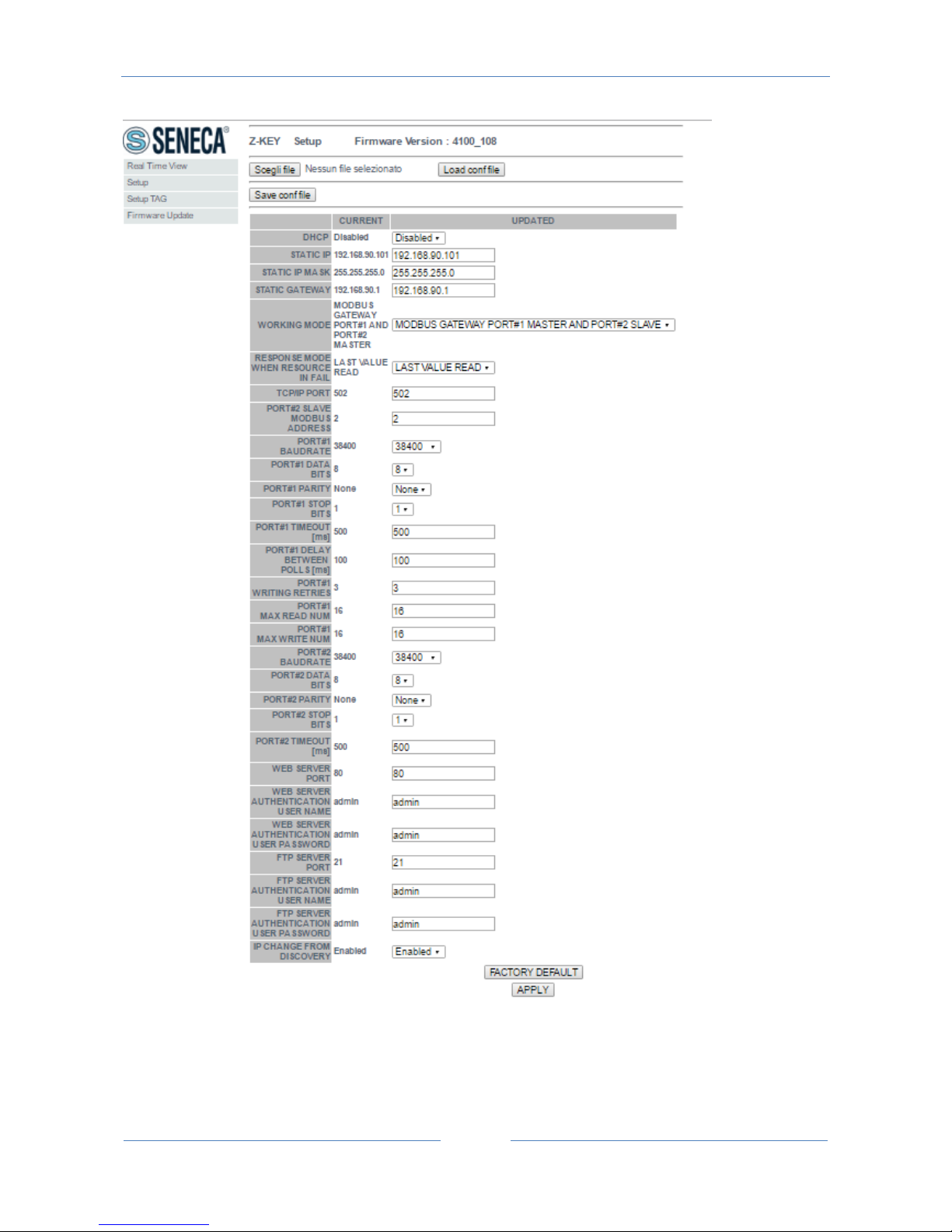
Now the Webserver can be used for configuring the Z-KEY module, all parameters are visible clicking on
“Setup” button to the left of the screen:
Page 47
USER MANUAL – Z-KEY
47
On the first column represents the parameter name, the second column (current) it’s the current
parameter value. The last column can be used for changing the current configuration.
Page 48

USER MANUAL – Z-KEY
48
When a configuration it’s made you must confirm with “APPLY”, then the new configuration became
operative.
If you need to reset to the default parameters click on “FACTORY DEFAULT” button.
In this page you can save and load a previous configuration (a configuration is made of Configuration and
Tags configuration).
The parameters are explained below:
DHCP
Disable: A static Ip address is used
Enable: The IP address, the IP-Mask and the Gateway address are obtained from the DHCP server.
The Z-KEY IP address can be read from the USB port with the Easy Setup test configuration, or with the
Seneca Discovery utility (see the Z-KEY section on seneca web site for download).
STATIC IP ADDRESS
Static IP address when DHCP is Disable
STATIC IP MASK
mask when DHCP is Disable
STATIC GATEWAY
Gateway address when DHCP is Disable
WORKING MODE
Select the Modbus Gateway working mode, select also which port must be master and slave.
RESPONSE MODE
Select which type of response do you want when a Modbus slave don’t respond to a modbus request. You
can select from
Page 49

USER MANUAL – Z-KEY
49
Last value read (the value is freezed to the last value read)
Exception (Z-KEY exception response)
TCP/IP PORT
TCP-IP port for Modbus TCP-IP Server protocol (Max 8 clients)
PORT #n MODBUS SLAVE ADDRESS
If you have selected the port 1 into Modbus Slave mode, select the Modbus Station address
PORT #1 BAUDRATE
Used to Set the port baudrate
PORT #1 BITS
Used to Set the number of bits for the serial communication.
PORT #1 PARITY
Used to Set the port parity (None, Odd or even)
PORT #1 STOP BITS
Used to Set the port parity (1 or 2; note that if the parity is set, only 1 bit can be used)
PORT #1 TIMEOUT
Used to Set the timeout on Modbus Master mode before making a new call
PORT #1 DELAY BETWEEN POLLS
Used to Set the delay between two Modbus Master request
Page 50

USER MANUAL – Z-KEY
50
PORT #1 WRITING RETRIES
Used to Set the retries to write a Modbus register into Modbus Master mode
PORT #1 MAX WRITE NUM
Used to Set the maximum number of registers that can be written with the Modbus function “Write Multiple
Registers” or “Write Multiple Coil”.
PORT #1 MAX READ NUM
Used to Set the maximum number of registers that can be read with the Modbus function “Read Multiple
Registers” or “Read Multiple Coils”.
PORT #2 BAUDRATE
Used to Set the port baudrate
PORT #2 BITS
Used to Set the number of bits for the serial communication.
PORT #2 PARITY
Used to Set the port parity (None, Odd or even)
PORT #2 STOP BITS
Used to Set the port parity (1 or 2; note that if the parity is set, only 1 bit can be used)
PORT #2 TIMEOUT
Used to Set the timeout on Modbus Master mode before making a new call
PORT #2 MODBUS READING DELAY
Used to Set the delay between two Modbus Master request
Page 51

USER MANUAL – Z-KEY
51
PORT 2 MODBUS WRITING RETRIES
Used to Set the retries to write a Modbus register into Modbus Master mode
WEB SERVER PORT
Used to Set the TCP-IP port for the Webserver
WEB SERVER AUTHENTICATION USER NAME
Used to Set the User Name for accessing the Webserver (if User Name and Password are leave empty no
authentication is require for webserver access)
WEB SERVER AUTHENTICATION USER PASSWORD
Used to Set the Password for accessing the Webserver (if User Name and Password are leave empty no
authentication is require for webserver access)
FTP SERVER PORT
Used to Set the TCP-IP port for the FTP Server
FTP SERVER AUTHENTICATION USER NAME
Used to Set the User Name for accessing the FTP Server (if User Name and Password are leave empty no
authentication is require for webserver access)
FTP SERVER AUTHENTICATION USER PASSWORD
Used to Set the Password for accessing the FTP server (if User Name and Password are leave empty no
authentication is require for ftp access)
IP CHANGE FROM DISCOVERY
Used to Set if a user is allowed to change IP configuration from the software “Seneca Discovery Device”
Page 52
USER MANUAL – Z-KEY
52
WARNING!
REMEMBER ALWAYS TO CONFIGURE THE WEBSERVER AND FTP AUTHENTICATION USER NAME AND
PASSWORD FOR RESTRICT THE ACCESS TO THE FTP AND THE WEBSERVER. IF YOU LEAVE THE TWO
PARAMETERS TEXT BOXES BLANK NO AUTHENTICATION IT’S REQUIRED FOR ACCESS.
CAUTION!
If you are using Internet explorer 9 (or newer) you must enable the compatibility mode (see the arrow
below):
11.3. Modbus Gateway Tags Setup, export and import
The Z-KEY in Modbus Gateway mode needs to configure the Tags to put into the internal shared memory.
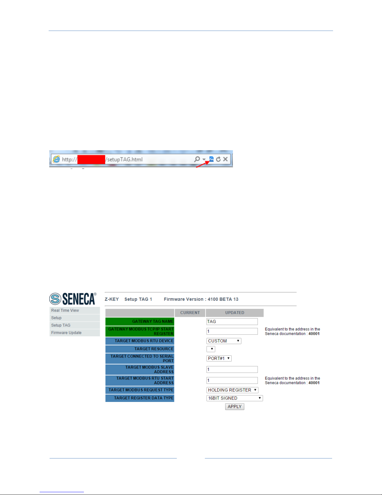
From the Webserver click on “Setup TAGs” button to the left menu:
Now you can ADD, Modify, Delete or move one tag. When you modify or add a tag a new page appear:
Gateway Tag Name
Page 53

USER MANUAL – Z-KEY
53
Set the Tag name to show in the Webserver realtime view
Gateway Modbus TCP-IP Start Register
Set the address where the tag is placed in shared memory for access from Modbus TCP-IP.
Target Modbus RTU Device
Select the Modbus RTU slave model from the Seneca database or select “custom” if you don’t use a Seneca
Modbus RTU slave.
Target Resource
If you are using a Seneca Modbus RTU Slave select the resource name from the Seneca database.
Target Connected to serial port
Select at which Z-KEY serial port is connected the modbus rtu slave device.
Target Modbus RTU Slave Station Address
Select the Device Modbus Station Address (also named Modbus node address).
Target Modbus RTU start register
Select the Modbus RTU slave start register TAG
Modbus Request Type
Select the Modbus Register Request type from:
Coil
Discrete Input
Holding Register
Input Register
Page 54

USER MANUAL – Z-KEY
54
Data Type
Select the TAG variable type from:
16 BITS UNSIGNED: 1 modbus register, from 0 to 65535
16 BITS SIGNED: 1 modbus register, from -32768 to +32767
32 BITS UNSIGNED MSW : 2 modbus registers with the lower address Modbus register that hold the Most
Significant Word, from 0 to 4294967295
32 BITS UNSIGNED LSW : 2 modbus registers with the lower address Modbus register that hold the Less
Significant Word, from 0 to 4294967295
32 BITS SIGNED MSW : 2 modbus registers with the lower address Modbus register that hold the Most
Significant Word, from -2147483648 to +2147483647
32 BITS SIGNED LSW : 2 modbus registers with the lower address Modbus register that hold the Less
Significant Word, from -2147483648 to +2147483647
FLOAT MSW : 2 modbus registers with the lower address Modbus register that hold the Most Significant
Word, Floating point single precision (IEEE 758-2008)
FLOAT LSW : 2 modbus registers with the lower address Modbus register that hold the Less Significant
Word, Floating point single precision (IEEE 758-2008)
BIT : 1 Boolean coil or Discrete input register
this field is automatically filled if you have select a Seneca Device into the “Device” field.
WARNING!
All 32 bits values are stored into 2 consecutive registers, for example:
TAG Totalizer 1 in unsigned 32 bits MSW type is stored into registers 40016 and 40017:
The most significant word is the register 40016, the less significant word is the 40017.
So the 32bits value is obtained by the following relation:
𝑇𝑜𝑡𝑎𝑙𝑖𝑧𝑒𝑟1=𝑅𝑒𝑔(40017)+(𝑅𝑒𝑔(40016)×216)=
𝑅𝑒𝑔(40017)+(𝑅𝑒𝑔(40016)×65536)
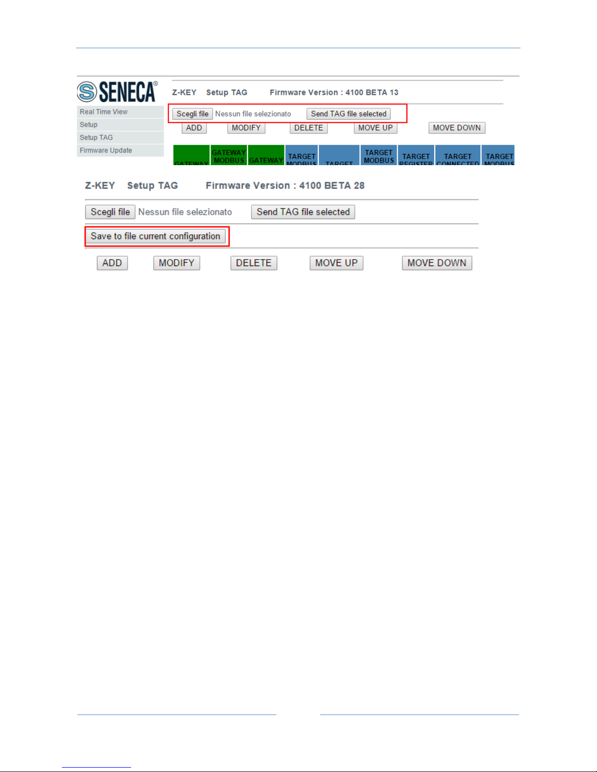
The Tags setup can be imported/exported from/to a “.cgi” file:
Page 55
USER MANUAL – Z-KEY
55
Note that a .cgi file can be also imported/exported from/to the Z-KEY Excel template.
11.4. Modbus Gateway Real Time view
Where the TAG are setup it’s possible to view in real time the communication from the webserver.
The real time view will show the TCP-IP configuration and the TAGS info.
The Tags info include: The TAG Name, the Gateway TAG Modbus Address, the Tag value and the TAG status
(OK = read ok, FAIL = read fail).
This Real Time View is very useful for connecting Mobile devices.
11.5. Import/Export TAGs setup
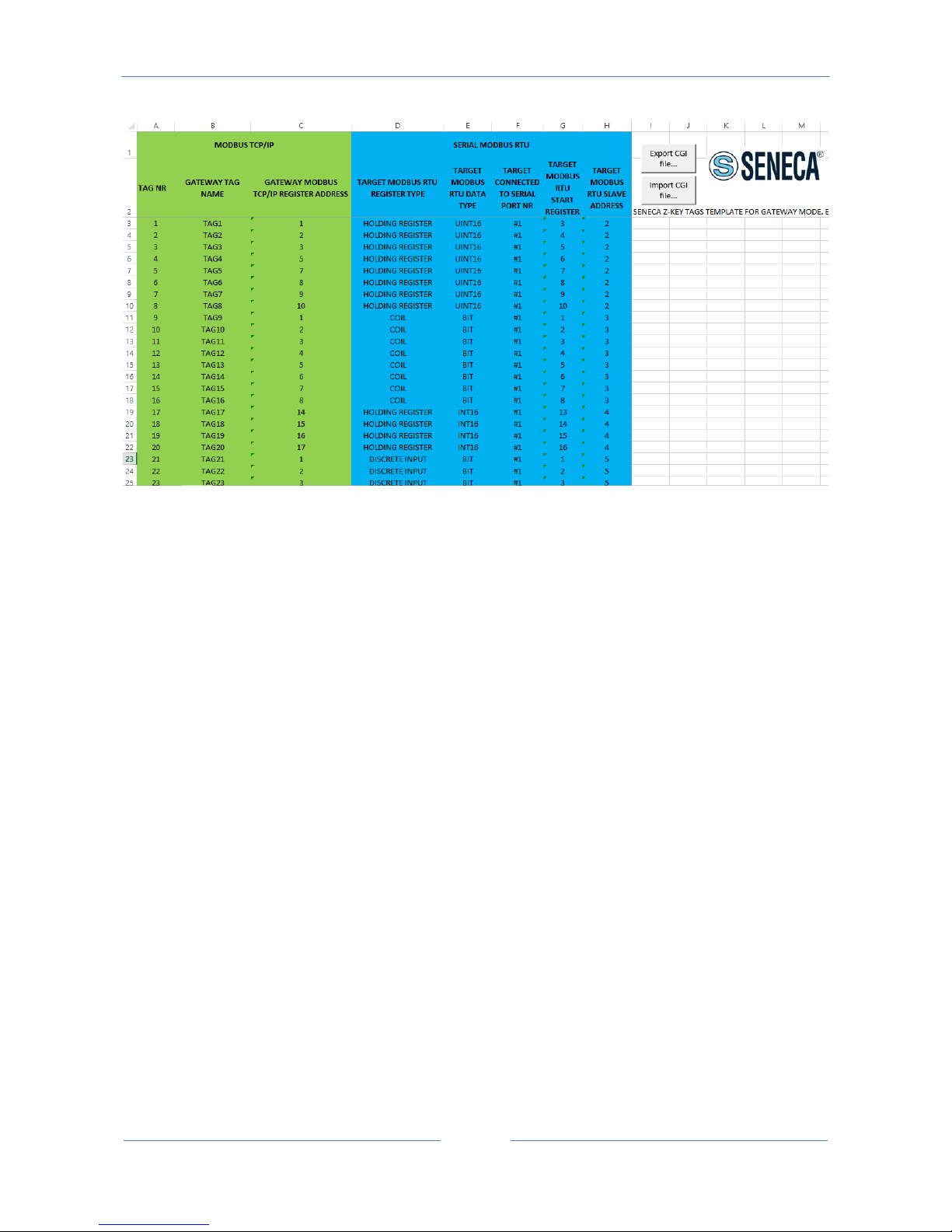
Preparing the Tag configuration can be a frustrating operation if it’s made with the webserver, so a
Microsoft Excel™ Template is available for create a .bin file to import to the Z-KEY.
This operation drastically speed up the TAG configuration.
The template can be freely downloaded from the seneca website into the Z-KEY section.
Page 56
USER MANUAL – Z-KEY
56
TAG NR
The tag index from 1 to 500
Gateway Tag Name
Enter the Tag mnemonic name
Gateway Modbus TCP-IP Register Address
Enter the TAG register address that will be accessed from TCP-IP (also from serial port if slave mode is
configured). For Seneca Modbus Standard address 1 holding register is equivalent to 40001, address 2 to
40002 etc… .
Target Modus RTU REGISTER TYPE
Select the register type from the combobox list
Target Modus RTU DATA TYPE
Select the target modbus rtu register type
Target Connected to serial port NR
Select the serial port where the slave modbus is connected to
Target Modbus RTU Start Register
Enter the Modbus Slave start register (if holding register 1=40001 etc…)
Page 57

USER MANUAL – Z-KEY
57
Target Modbus RTU Slave Address
Enter the Modbus RTU Slave Station address
The setup can be exported from Excel to a .cgi file (for to be imported in the webserver) or imported from a
.cgi file (exported from the webserver).
Page 58
USER MANUAL – Z-KEY
58
12. Gateway Modbus TCP-IP / Modbus RTU (2 port Slaves)
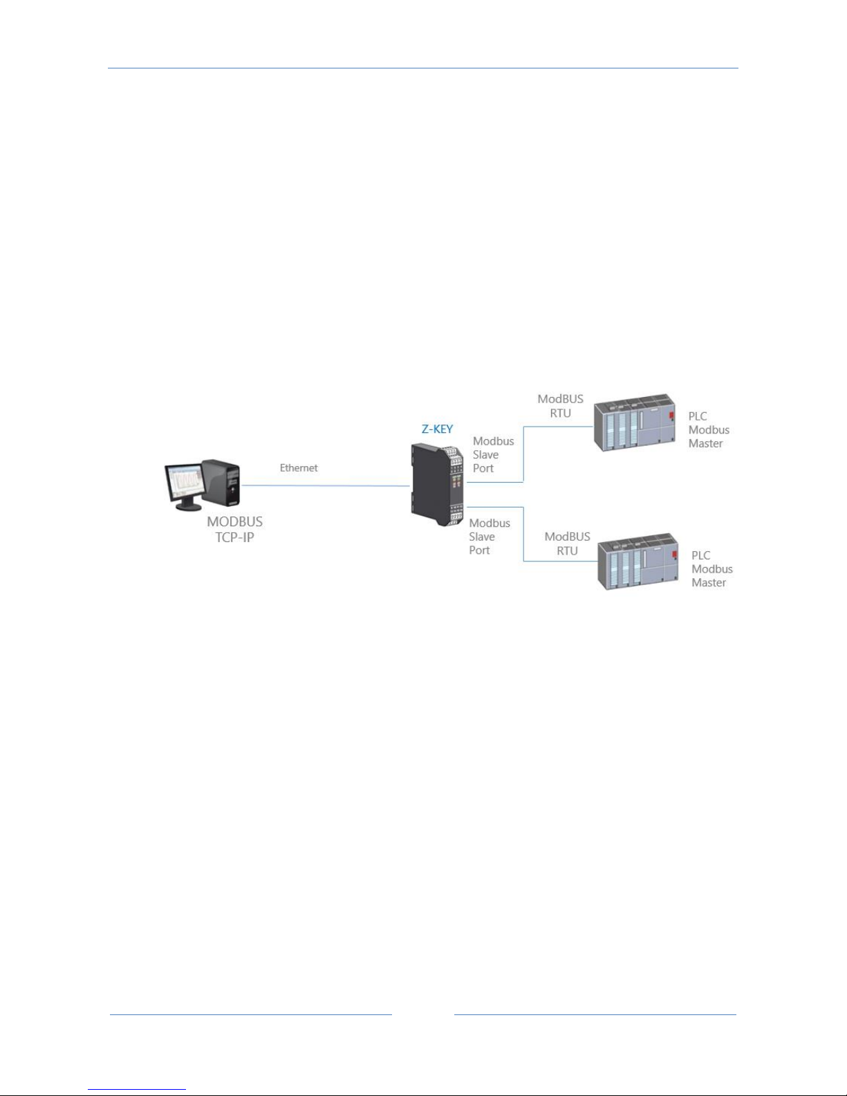
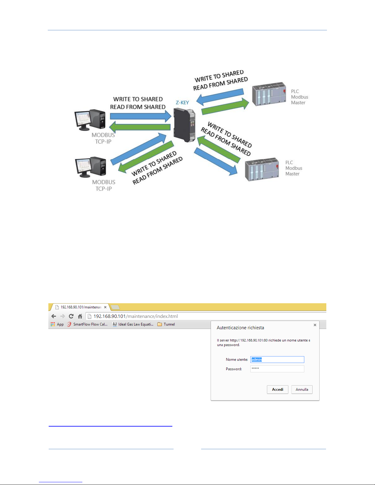
In this scenario a Modbus TCP-IP master is connected with ethernet to Z-KEY, Two PLCs with only the
Modbus Master protocol are connected to the Z-KEY Modbus slave ports. By this ports the PLC can
communicate with each other.
A typical LAN connection is represented into this figure:
12.1. How it works
A lot of PLCs have the limitation that only the Modbus Master protocol is implemented. When values from the
Modbus Slaves must be shared with another PLC/SCADA/DATALOGGER etc.. the Z-KEY can be configured in Gateway
mode with the 2 ports in Modbus Slave.
In this way the two PLCs and the Ethernet Clients can freely write/read the Z-KEY Shadow memory for data sharing:
Page 59
USER MANUAL – Z-KEY
59
The Z-KEY shared memory can be freely read and written from Ethernet or/and from the serial ports.
The Shared memory registers must be defined before with the setup TAG section.
12.2. Webserver configuration Gateway Modbus TCP-IP / Modbus RTU (2 port
Slaves)
Connect to the webserver by entering the ip address, by default:
http://192.168.90.101/maintenance/index.html
Page 60

USER MANUAL – Z-KEY
60
Enter the user name and password, by default:
User: admin
Password: admin
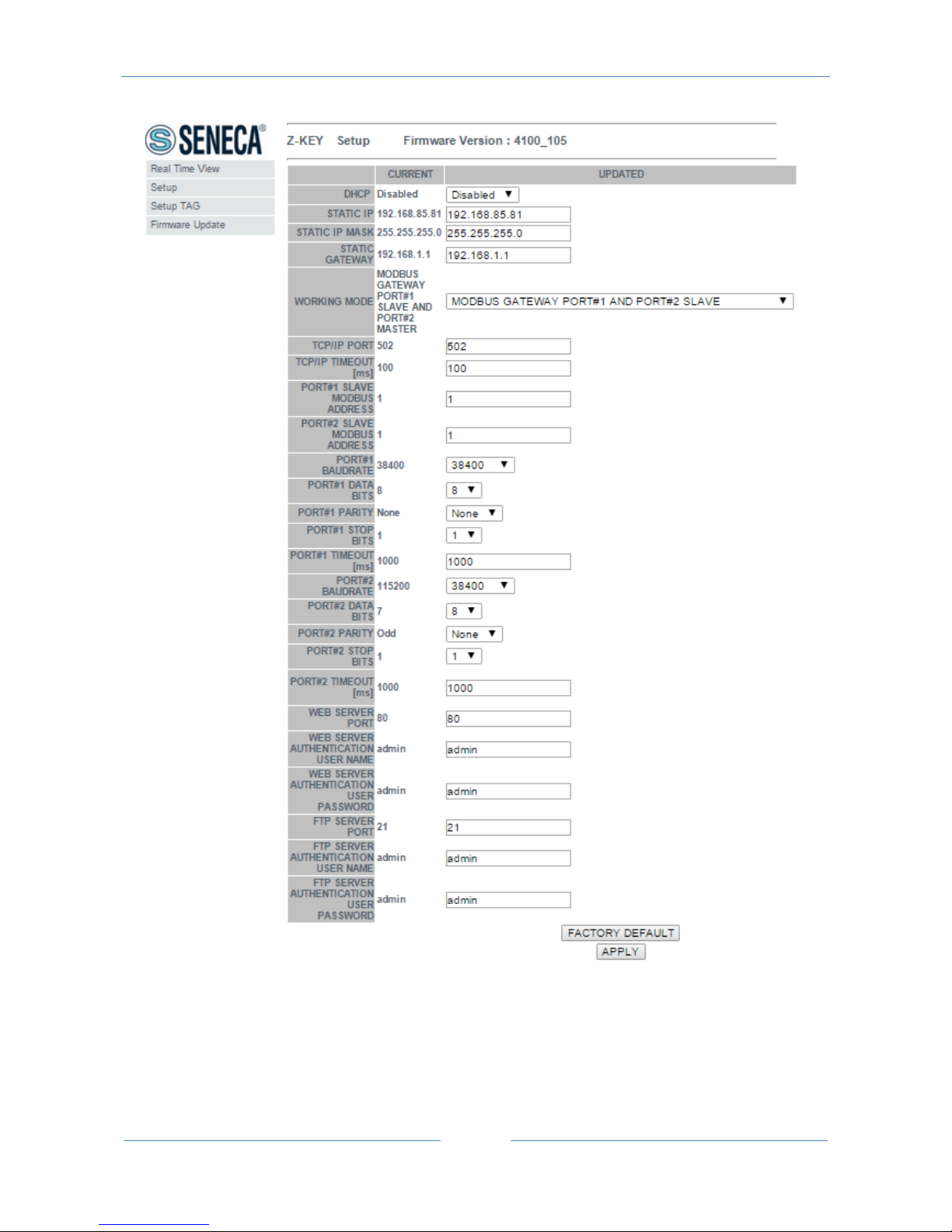
Now the Webserver can be used for configuring the Z-KEY module, all parameters are visible clicking on
“Setup” button to the left of the screen:
Page 61
USER MANUAL – Z-KEY
61
On the first column represents the parameter name, the second column (current) it’s the current
parameter value. The last column can be used for changing the current configuration.
When a configuration it’s made you must confirm with “APPLY”, then the new configuration became
operative.
Page 62

USER MANUAL – Z-KEY
62
If you need to reset to the default parameters click on “FACTORY DEFAULT” button.
The parameters are explained below:
DHCP
Disable: A static Ip address is used
Enable: The IP address, the IP-Mask and the Gateway address are obtained from the DHCP server.
The Z-KEY IP address can be read from the USB port with the Easy Setup test configuration, or with the
Seneca Discovery utility (see the Z-KEY section on seneca web site for download).
STATIC IP ADDRESS
Static IP address when DHCP is Disable
STATIC IP MASK
mask when DHCP is Disable
STATIC GATEWAY
Gateway address when DHCP is Disable
WORKING MODE
Select the Modbus Gateway working mode with port 1 and port2 modbus slave.
RESPONSE MODE
Select which type of response do you want when a Modbus slave don’t respond to a modbus request. You
can select from
Last value read (the value is freezed to the last value read)
Exception (Z-KEY exception response)
TCP/IP PORT
TCP-IP port for Modbus TCP-IP Server protocol (Max 8 clients)
Page 63

USER MANUAL – Z-KEY
63
PORT #1 MODBUS SLAVE ADDRESS
Select the Modbus Slave Station address for this Port
PORT #2 MODBUS SLAVE ADDRESS
Select the Modbus Slave Station address for this Port
PORT #1 BAUDRATE
Used to Set the port baudrate
PORT #1 BITS
Used to Set the number of bits for the serial communication.
PORT #1 PARITY
Used to Set the port parity (None, Odd or even)
PORT #1 STOP BITS
Used to Set the port parity (1 or 2; note that if the parity is set, only 1 bit can be used)
PORT #1 TIMEOUT
Used to Set the timeout on Modbus Master mode before making a new call
PORT #2 BAUDRATE
Used to Set the port baudrate
PORT #2 BITS
Used to Set the number of bits for the serial communication.
Page 64

USER MANUAL – Z-KEY
64
PORT #2 PARITY
Used to Set the port parity (None, Odd or even)
PORT #2 STOP BITS
Used to Set the port parity (1 or 2; note that if the parity is set, only 1 bit can be used)
PORT #2 TIMEOUT
Used to Set the timeout on Modbus Master mode before making a new call
WEB SERVER PORT
Used to Set the TCP-IP port for the Webserver
WEB SERVER AUTHENTICATION USER NAME
Used to Set the User Name for accessing the Webserver (if User Name and Password are leave empty no
authentication is require for webserver access)
WEB SERVER AUTHENTICATION USER PASSWORD
Used to Set the Password for accessing the Webserver (if User Name and Password are leave empty no
authentication is require for webserver access)
FTP SERVER PORT
Used to Set the TCP-IP port for the FTP Server
FTP SERVER AUTHENTICATION USER NAME
Used to Set the User Name for accessing the FTP Server (if User Name and Password are leave empty no
authentication is require for webserver access)
Page 65
USER MANUAL – Z-KEY
65
FTP SERVER AUTHENTICATION USER PASSWORD
Used to Set the Password for accessing the FTP server (if User Name and Password are leave empty no
authentication is require for ftp access)
WARNING!
REMEMBER ALWAYS TO CONFIGURE THE WEBSERVER AND FTP AUTHENTICATION USER NAME AND
PASSWORD FOR RESTRICT THE ACCESS TO THE FTP AND THE WEBSERVER. IF YOU LEAVE THE TWO
PARAMETERS TEXT BOXES BLANK NO AUTHENTICATION IT’S REQUIRED FOR ACCESS.
CAUTION!
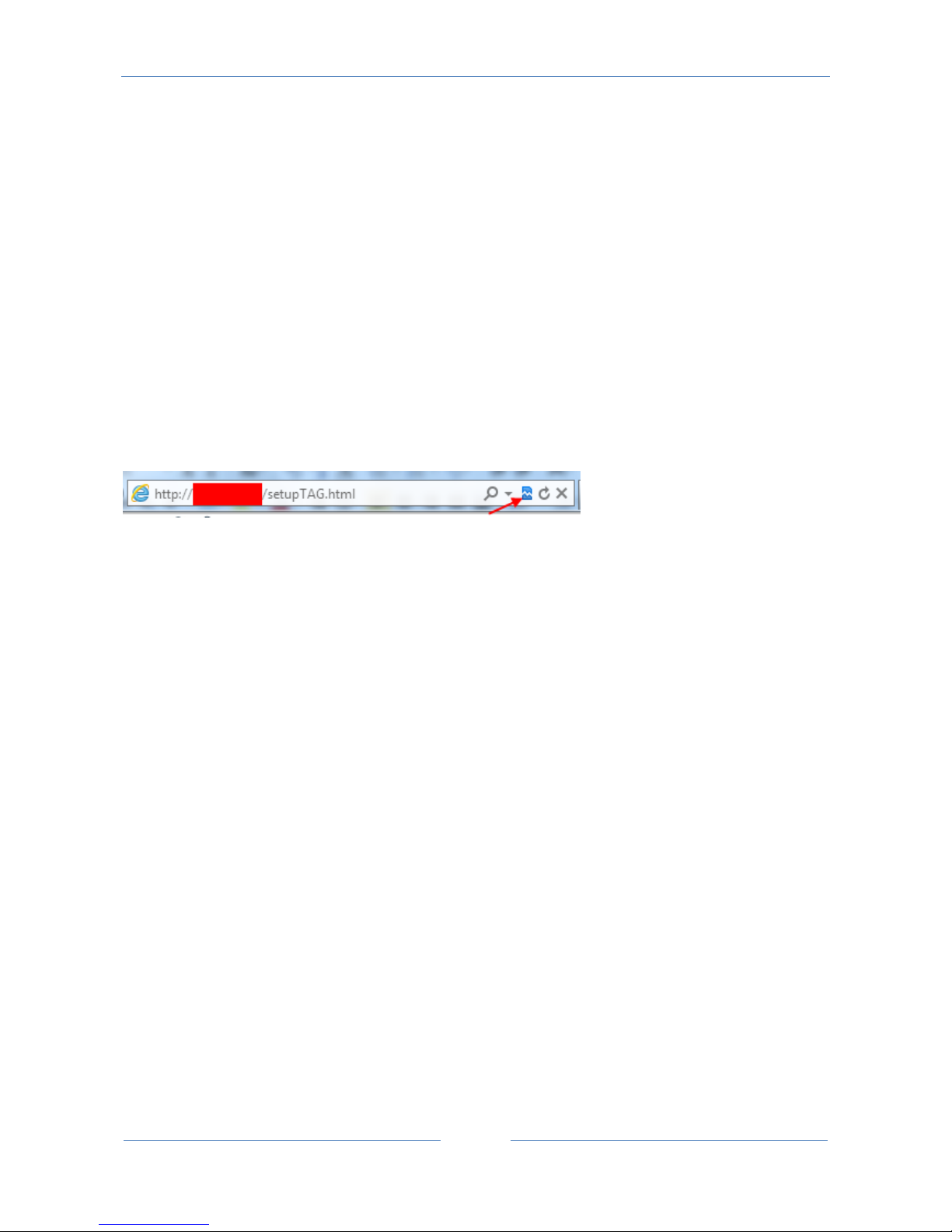
If you are using Internet explorer 9 (or newer) you must enable the compatibility mode (see the arrow
below):
12.3. Modbus Gateway Tags Setup, export and import
The Z-KEY in Modbus Gateway mode needs to configure the Tags to put into the internal shared memory.
From the Webserver click on “Setup TAGs” button to the left menu:
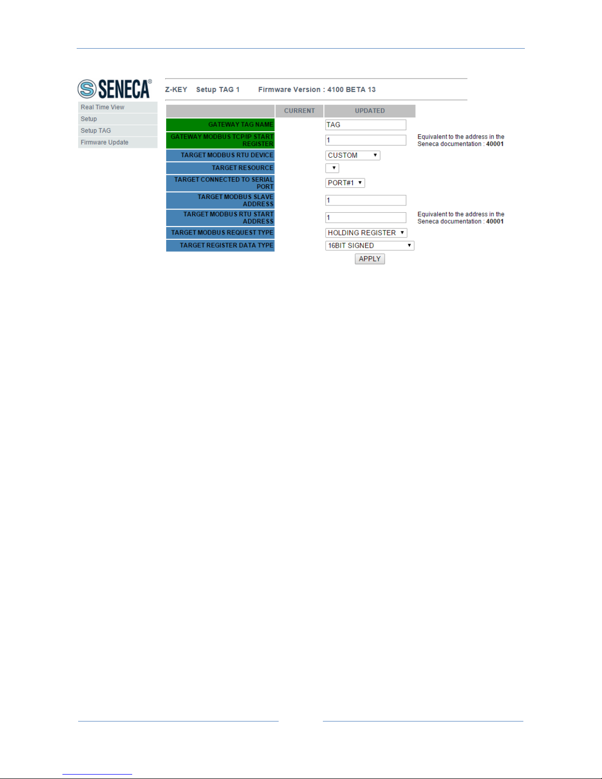
Now you can ADD, Modify, Delete or move one tag. When you modify or add a tag a new page appear:
Page 66
USER MANUAL – Z-KEY
66
Gateway Tag Name
Set the Tag name to show in the Webserver realtime view
Gateway Modbus TCP-IP Start Register
Set the address where the tag is placed in shared memory for access from Modbus TCP-IP.
Target Modbus RTU Device
Select the Modbus RTU slave model from the Seneca database or select “custom” if you don’t use a Seneca
Modbus RTU slave.
Target Resource
If you are using a Seneca Modbus RTU Slave select the resource name from the Seneca database.
Target Connected to serial port
Select at which Z-KEY serial port is connected the modbus rtu slave device.
Target Modbus RTU Slave Station Address
Page 67

USER MANUAL – Z-KEY
67
Select the Device Modbus Station Address (also named Modbus node address).
Target Modbus RTU start register
Select the Modbus RTU slave start register TAG
Modbus Request Type
Select the Modbus Register Request type from:
Coil
Discrete Input
Holding Register
Input Register
Data Type
Select the TAG variable type from:
16 BITS UNSIGNED: 1 modbus register, from 0 to 65535
16 BITS SIGNED: 1 modbus register, from -32768 to +32767
32 BITS UNSIGNED MSW : 2 modbus registers with the lower address Modbus register that hold the Most
Significant Word, from 0 to 4294967295
32 BITS UNSIGNED LSW : 2 modbus registers with the lower address Modbus register that hold the Less
Significant Word, from 0 to 4294967295
32 BITS SIGNED MSW : 2 modbus registers with the lower address Modbus register that hold the Most
Significant Word, from -2147483648 to +2147483647
32 BITS SIGNED LSW : 2 modbus registers with the lower address Modbus register that hold the Less
Significant Word, from -2147483648 to +2147483647
FLOAT MSW : 2 modbus registers with the lower address Modbus register that hold the Most Significant
Word, Floating point single precision (IEEE 758-2008)
FLOAT LSW : 2 modbus registers with the lower address Modbus register that hold the Less Significant
Word, Floating point single precision (IEEE 758-2008)
BIT : 1 Boolean coil or Discrete input register
Page 68
USER MANUAL – Z-KEY
68
this field is automatically filled if you have select a Seneca Device into the “Device” field.
WARNING!
All 32 bits values are stored into 2 consecutive registers, for example:
TAG Totalizer 1 in unsigned 32 bits MSW type is stored into registers 40016 and 40017:
The most significant word is the register 40016, the less significant word is the 40017.
So the 32bits value is obtained by the following relation:
𝑇𝑜𝑡𝑎𝑙𝑖𝑧𝑒𝑟1=𝑅𝑒𝑔(40017)+(𝑅𝑒𝑔(40016)×216)=
𝑅𝑒𝑔(40017)+(𝑅𝑒𝑔(40016)×65536)
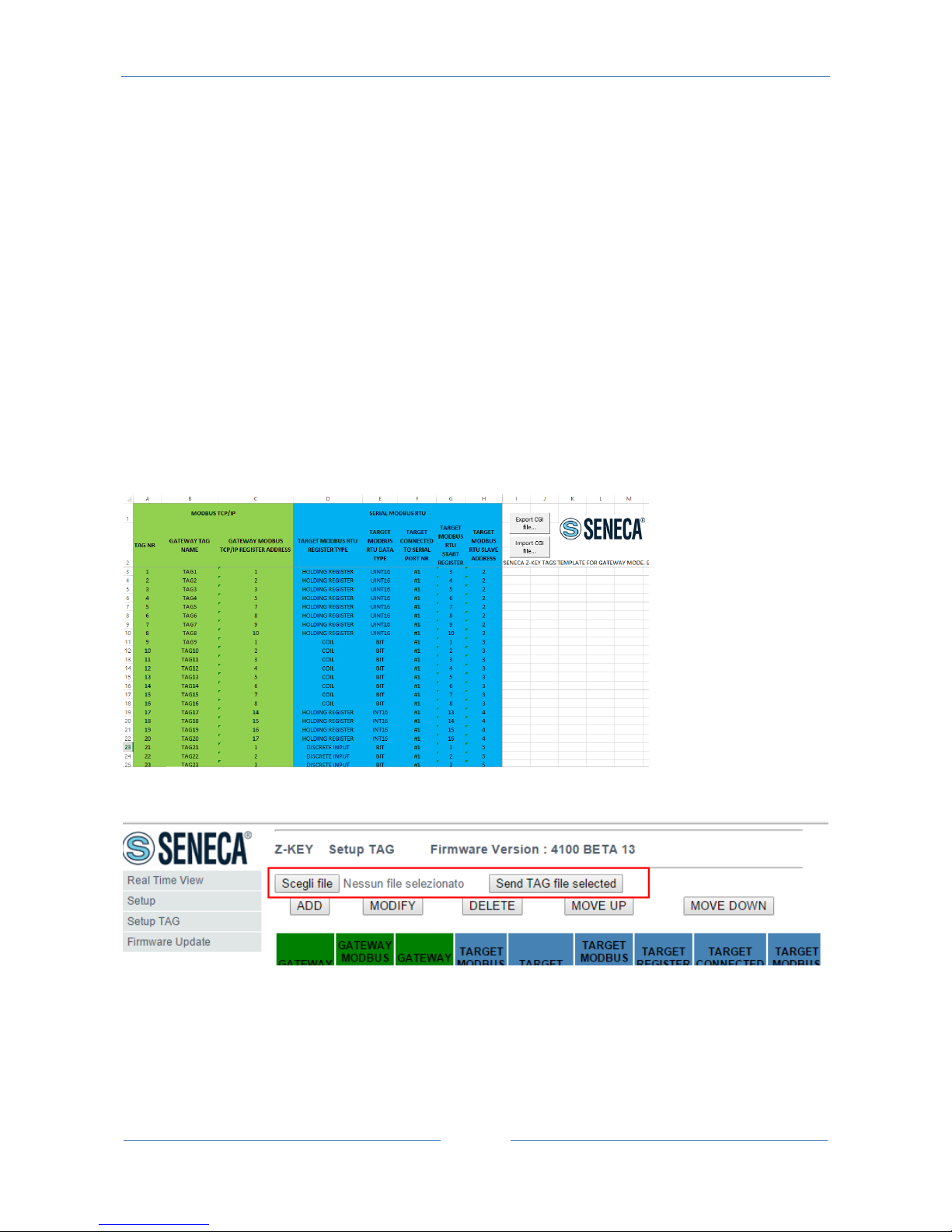
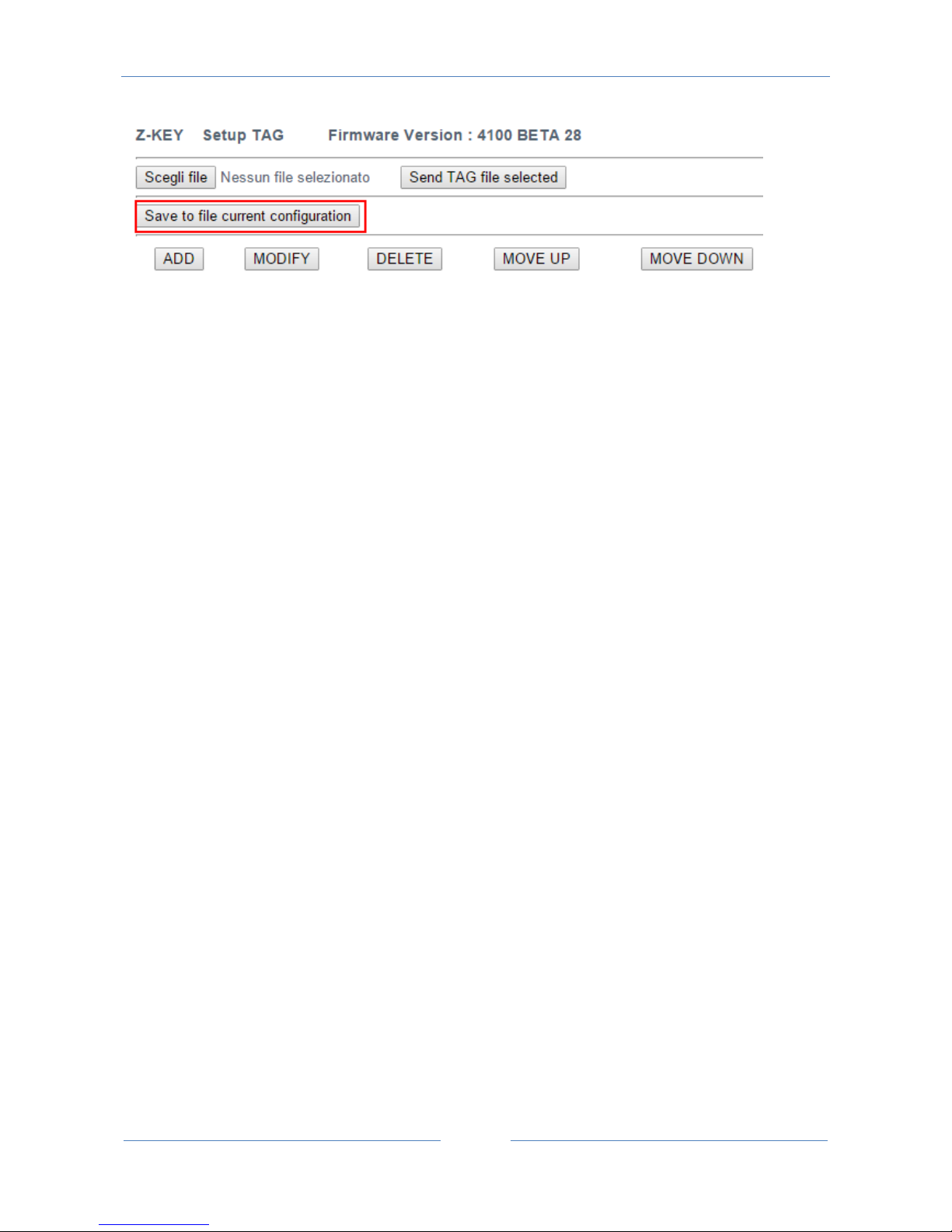
The Tags setup can be imported/exported from/to a “.cgi” file:
Page 69
USER MANUAL – Z-KEY
69
Note that a .cgi file can be also imported/exported from/to the Z-KEY Excel template.
12.4. Modbus Gateway Real Time view
Where the TAG are setup it’s possible to view in real time the communication from the webserver.
The real time view will show the TCP-IP configuration and the TAGS info.
The Tags info include: The TAG Name, the Gateway TAG Modbus Address, the Tag value and the TAG status
(OK = read ok, FAIL = read fail).
This Real Time View is very useful for connecting Mobile devices.
12.5. Using the Microsoft Excel ™ template for Tags configuration
Preparing the Tag configuration can be a frustrating operation if it’s made with the webserver so a
Microsoft Excel™ Template is available for create a .bin file to import to the Z-KEY.
This operation drastically speed up the TAG configuration.
The template can be freely downloaded from the seneca website into the Z-KEY section.
TAG NR
The tag index from 1 to 500
Gateway Tag Name
Enter the Tag mnemonic name
Gateway Modbus TCP-IP Register Address
Page 70

USER MANUAL – Z-KEY
70
Enter the TAG register address that will be accessed from TCP-IP (also from serial port if slave mode is
configured). For Seneca Modbus Standard address 1 holding register is equivalent to 40001, address 2 to
40002 etc… .
Target Modus RTU REGISTER TYPE
Select the register type from the combobox list
Target Modus RTU DATA TYPE
Select the target modbus rtu register type
Target Connected to serial port NR
Select the serial port where the slave modbus is connected to
Target Modbus RTU Start Register
Enter the Modbus Slave start register (if holding register 1=40001 etc…)
Target Modbus RTU Slave Address
Enter the Modbus RTU Slave Station address
The setup can be exported from Excel to a .cgi file (for to be imported in the webserver) or imported from a
.cgi file (exported from the webserver).
Page 71
USER MANUAL – Z-KEY
71
13. Remote Serial Com Port
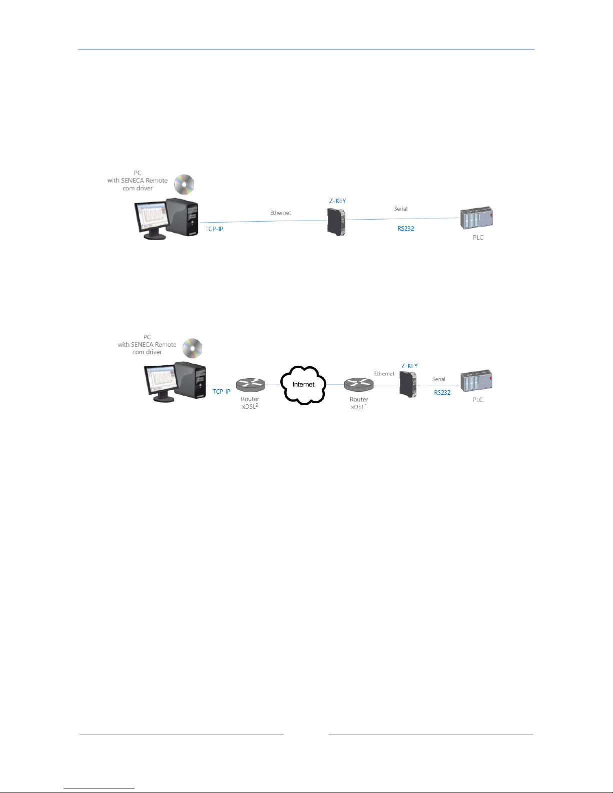
In this scenario a Serial device must be connected to a PC but the device is too far away from the PC.
The Z-Key can be used for extend the serial port using the ethernet connection:
Also a connection through internet can be made (typically for remote maintenance of machines, PLC etc…):
For internet communication the Router connected to the Z-KEY must have a static ip address.
NOTE:
Z-KEY, in Remote serial com port mode, supports one PC connection at a time.
NOTE:
For using the ZModem serial protocol with Z-KEY through internet, remember to activate the
protocol crash recovery option.
13.1. How it works
If a PC program has only the serial port support but you need to exit from the ethernet you can install the
Serial to Ethernet driver freely supplied by Seneca.
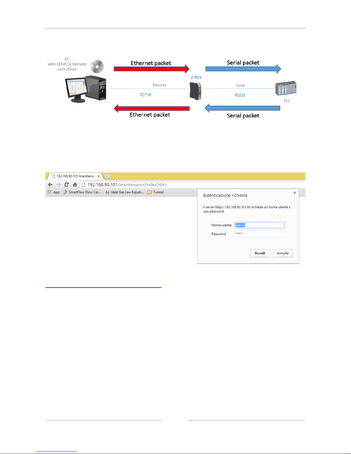
With this driver installed a couple of virtual serial port is created, using these serial ports from a pc
software the serial traffic will pass through ethernet. After that the Z-KEY will convert the ethernet traffic to
serial through the real serial port, also Z-KEY will reconvert to ethernet the serial communication responses.
Page 72
USER MANUAL – Z-KEY
72
13.2. Remote Serial Com Port Webserver configuration
Connect to the webserver by entering the ip address, by default:
http://192.168.90.101/maintenance/index.html
Enter the user name and password, by default:
User: admin
Password: admin
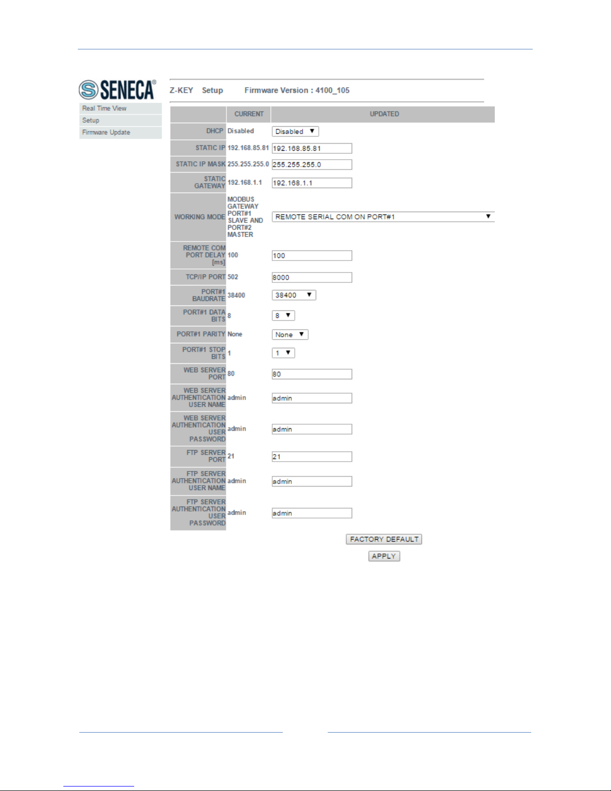
Now the Webserver can be used for configuring the Z-KEY module, all parameters are visible clicking on
“Setup” button to the left of the screen:
Page 73
USER MANUAL – Z-KEY
73
The first column represents the parameter name, the second column (current) it’s the current parameter
value. The last column can be used for changing the current configuration.
When a configuration it’s made you must confirm with “APPLY”, then the new configuration became
operative.
If you need to reset to the default parameters click on “FACTORY DEFAULT” button.
The parameters are explained below:
Page 74

USER MANUAL – Z-KEY
74
DHCP
Disable: A static Ip address is used
Enable: The IP address, the IP-Mask and the Gateway address are obtained from the DHCP server.
The Z-KEY IP address can be read from the USB port with the Easy Setup test configuration, or with the
Seneca Discovery utility (see the Z-KEY section on seneca web site for download).
STATIC IP ADDRESS
Static IP address when DHCP is Disable
STATIC IP MASK
mask when DHCP is Disable
STATIC GATEWAY
Gateway address when DHCP is Disable
WORKING MODE
Select the Remote COM Port working mode, select which serial port to use (remember that only port #2
can be configured in RS232 mode).
TCP/IP PORT
TCP-IP port for Remote com port mode (default port 8000)
REMOTE COM PORT DELAY
Enter the silence time after which the serial packet is sent to the Ethernet. Can be that this value must be
adjusted for your specific application if you encounter communication errors.
PORT #n BAUDRATE
Page 75

USER MANUAL – Z-KEY
75
Used to Set the port baudrate
PORT #n BITS
Used to Set the number of bits for the serial communication.
PORT #n PARITY
Used to Set the port parity (None, Odd or even)
PORT #n RS485 STOP BITS
Used to Set the port parity (1 or 2; note that if the parity is set, only 1 bit can be used)
WEB SERVER PORT
Used to Set the TCP-IP port for the Webserver
WEB SERVER AUTHENTICATION USER NAME
Used to Set the User Name for accessing the Webserver (if User Name and Password are leave empty no
authentication is require for webserver access)
WEB SERVER AUTHENTICATION USER PASSWORD
Used to Set the Password for accessing the Webserver (if User Name and Password are leave empty no
authentication is require for webserver access)
FTP SERVER PORT
Used to Set the TCP-IP port for the FTP Server
FTP SERVER AUTHENTICATION USER NAME
Used to Set the User Name for accessing the FTP Server (if User Name and Password are leave empty no
authentication is require for webserver access)
Page 76
USER MANUAL – Z-KEY
76
FTP SERVER AUTHENTICATION USER PASSWORD
Used to Set the Password for accessing the FTP server (if User Name and Password are leave empty no
authentication is require for ftp access)
WARNING!
REMEMBER ALWAYS TO CONFIGURE THE WEBSERVER AND FTP AUTHENTICATION USER NAME AND
PASSWORD FOR RESTRICT THE ACCESS TO THE FTP AND THE WEBSERVER. IF YOU LEAVE THE TWO
PARAMETERS TEXT BOXES BLANK NO AUTHENTICATION IT’S REQUIRED FOR ACCESS.
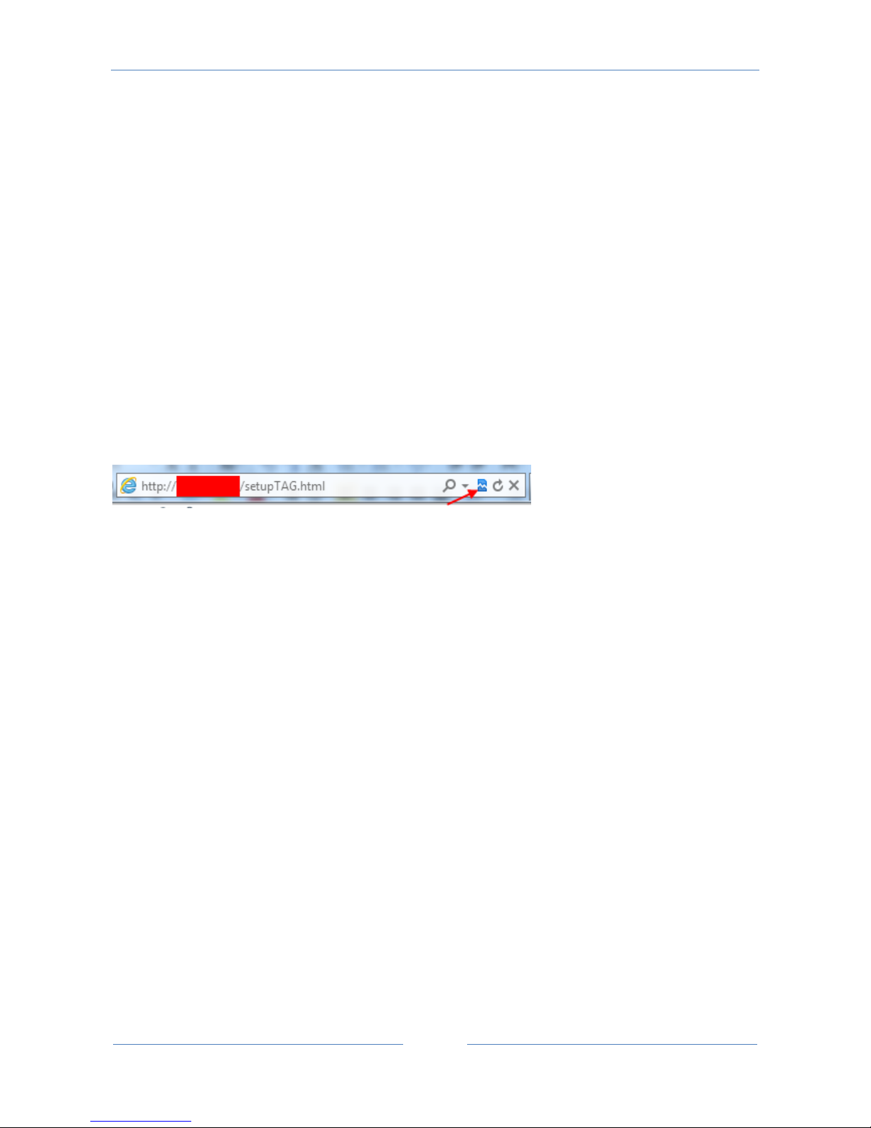
CAUTION!
If you are using Internet explorer 9 (or newer) you must enable the compatibility mode (see the arrow
below):
13.3. Seneca Serial to Ethernet Connect
For using Z-KEY in remote serial com port mode you need to install in a PC the Seneca Serial to Ethernet
Connect software.
13. 3 . 1 . Installing Seneca Serial to Ethernet Conne ct driver
Seneca Ethernet to Serial Connect runs on windows vista™, windows 7™, windows 8.1™ and windows 10™.
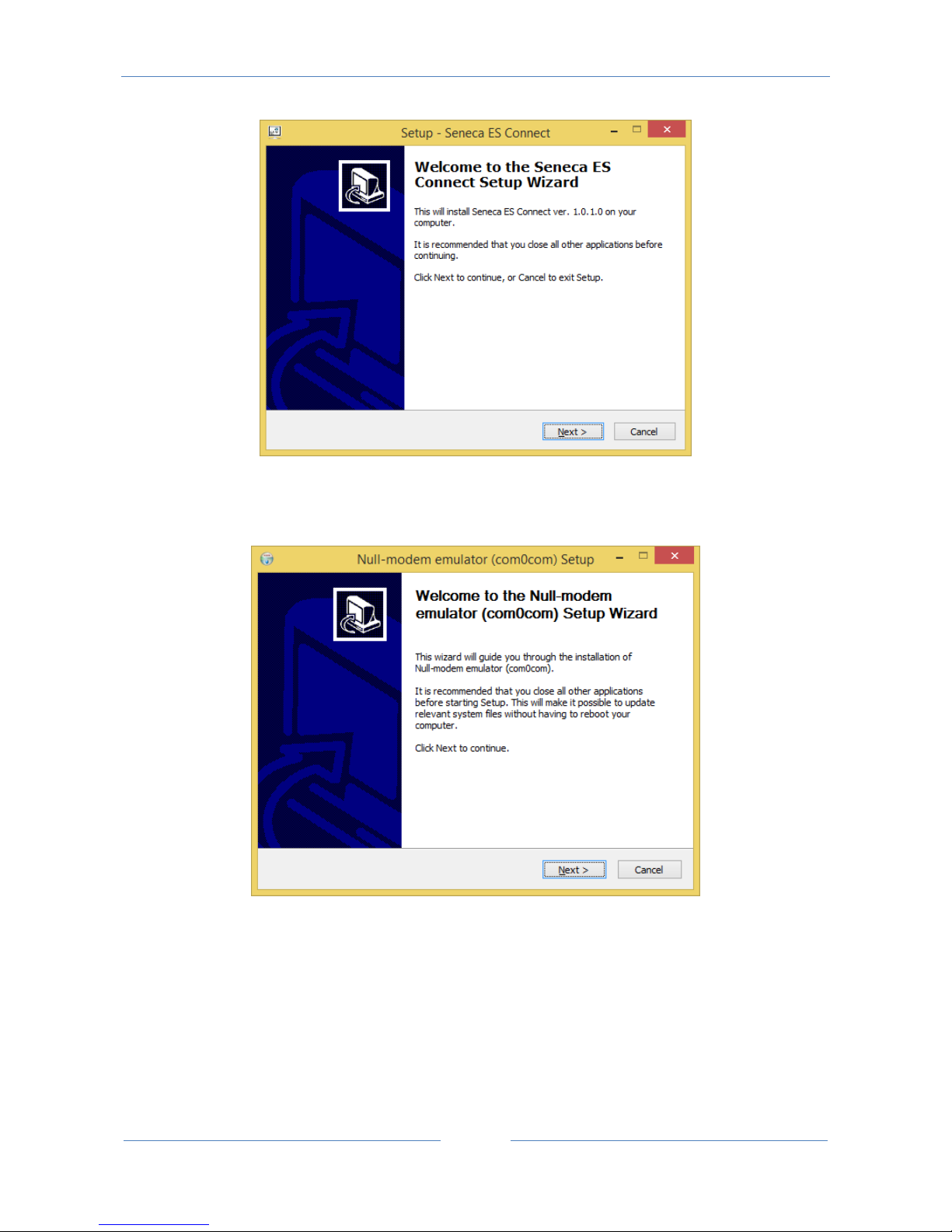
Double click the installer:
Page 77
USER MANUAL – Z-KEY
77
After that the com0com driver will be installed:
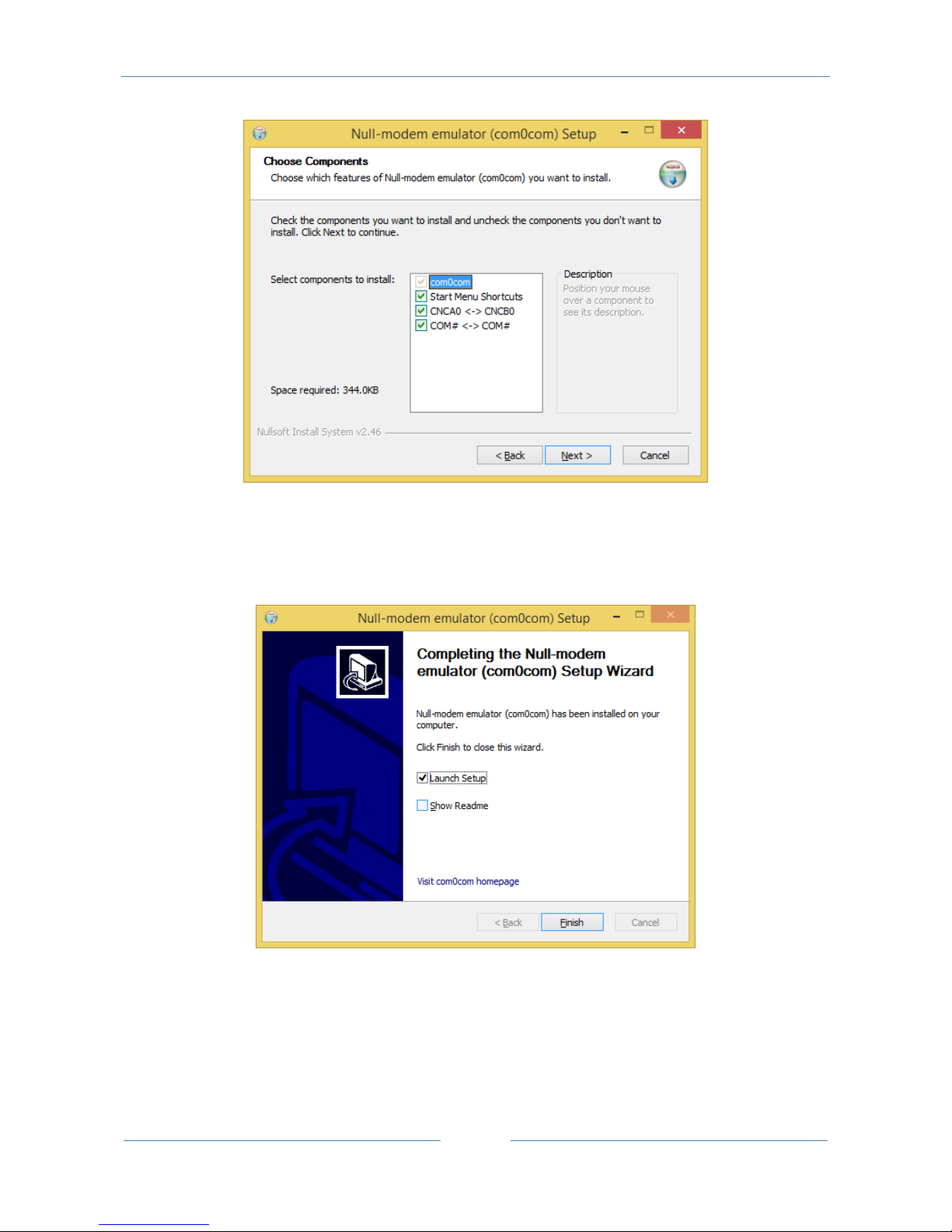
Select the CNCA0<->CNCB0 and the COM#<->COM# virtual port names:
Page 78
USER MANUAL – Z-KEY
78
Now Click on Launch Setup:
Press Finish, the com0com setup will open:
Page 79
USER MANUAL – Z-KEY
79
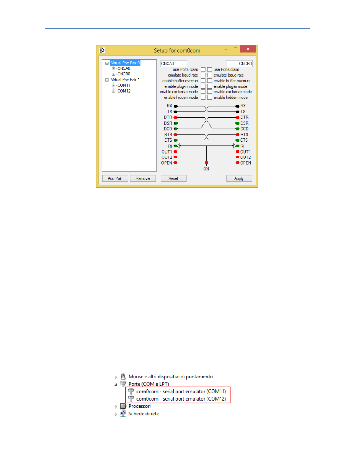
We have installed two Pairs of Virtual Ports:
CNCA0, CNCB0
And also:
COM11, COM12 (note that in your system the com# can be different)
The first Pair can be used in software that support the CNCA names, the other in software that support only the Ports
class.
If you need to add more virtual ports press the “Add Pair” button the select if you need or not a port class.
Confirm the driver installation with “Apply”.
The serial port emulator Couple COM11-COM12 will be available:
Page 80
USER MANUAL – Z-KEY
80
13. 3 . 2 . Select the Com port for Seneca Serial to Ethernet Connect
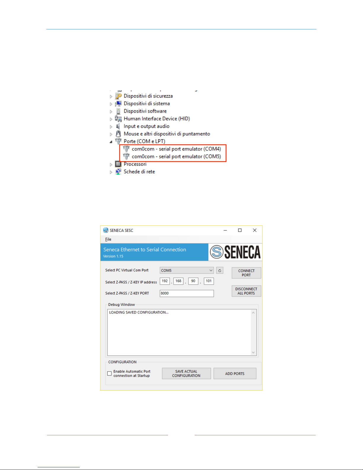
The driver installation will use the first 2 serial port that are free (in our case the driver has created the
COM4 and COM5 pair):
The Ethernet to serial connection software will use only one port (the right port in the com0com setup),
only the com0com ports will be displayed.
We connect the COM5 to the Seneca ES Connector:
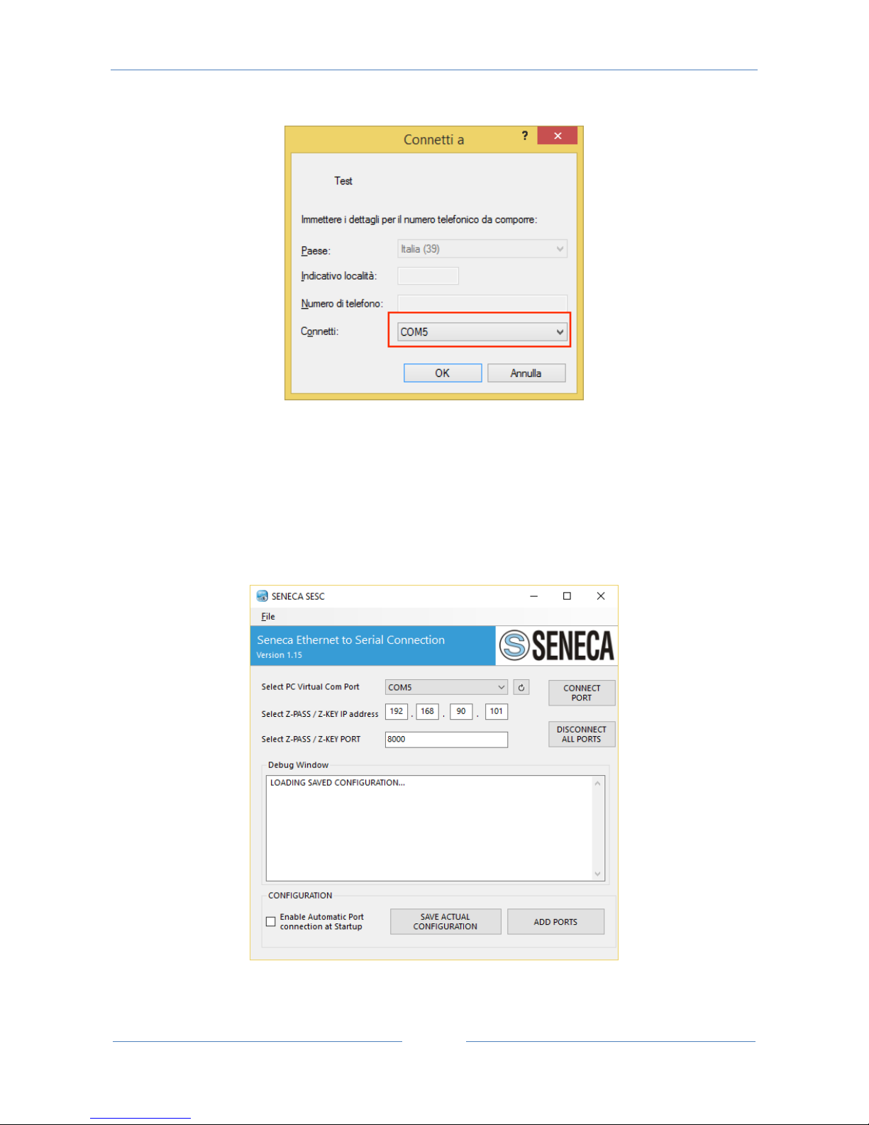
Now use the same COM5 (for example in a terminal software):
Page 81
USER MANUAL – Z-KEY
81
The COM5 is now connected to Z-KEY by the TCP port 8000:
13. 3 . 3 . Configuring Seneca Serial to Ethernet Connect
Select the Virtual COM Port
Select the Z-KEY IP address (default 192.168.90.101).
Page 82

USER MANUAL – Z-KEY
82
Select the TCP-IP port (default 8000).
Then click on “Connect PORT”.
If you need to connect another serial com to another Z-KEY configure the new com port and the new IP
addess then click on “Connect Port”.
For disconnect all Ports click on “Disconnect All Ports”.
For automatically connect the PC at startup save the configuration and enable the “Automatic Port
Connection at Startup” flag.
13. 3 . 4 . Debugging the Connection
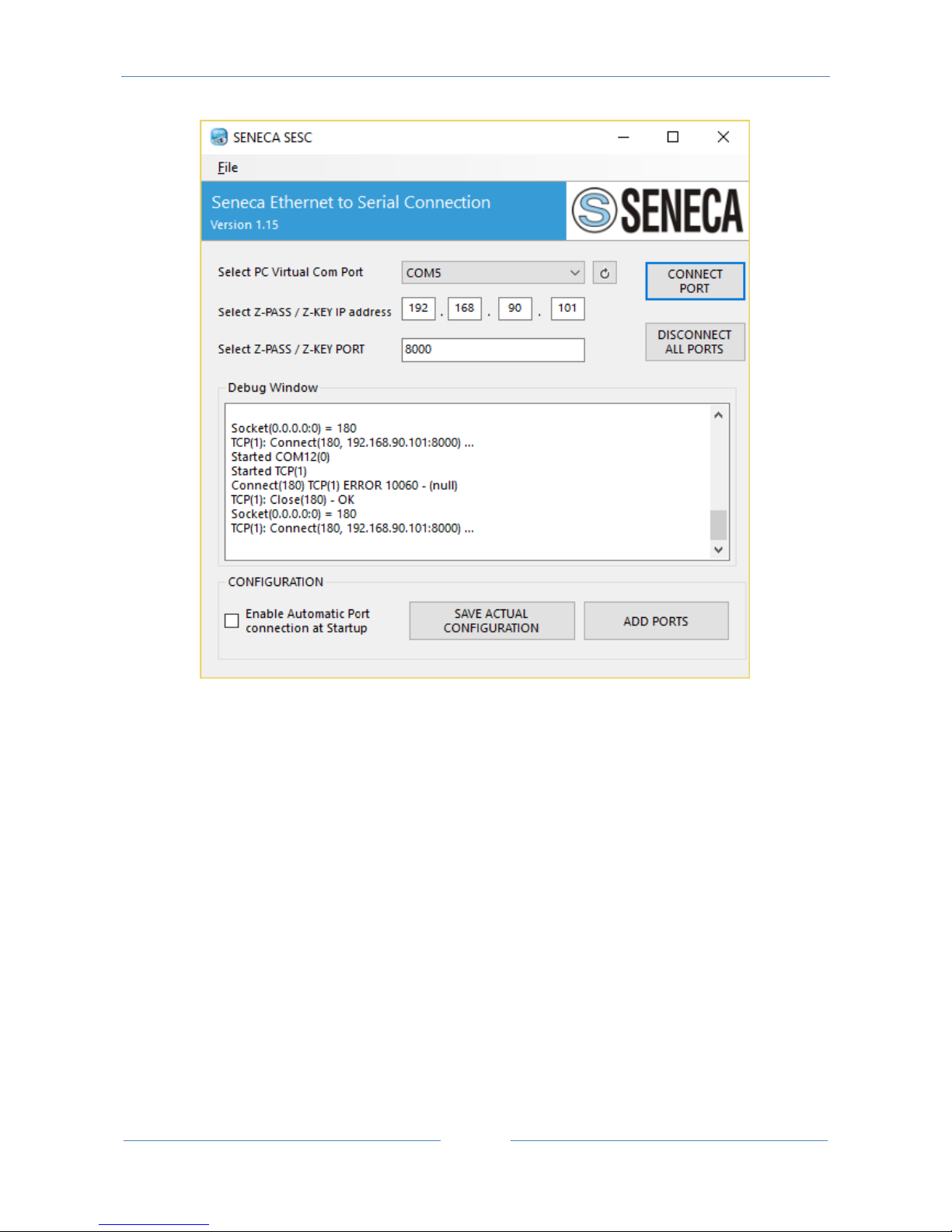
Before click on “Connect Port” you can select to open a Debug Window for verify the connection
configuration:
Then click on “Connect Port”:
If you see “Connect Error” like here:
Page 83
USER MANUAL – Z-KEY
83
Check the configuration (Z-KEY ip address and port).
13. 3 . 5 . Changing the COM port number
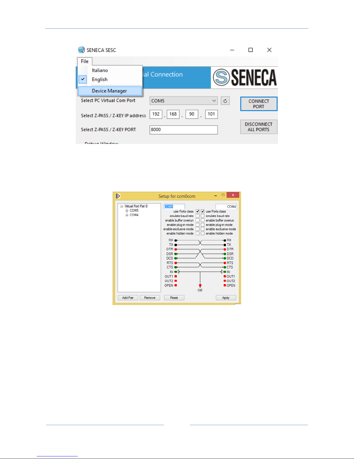
Old software can use only a little range of COM ports, so you may need to change the virtual COM number.
In Our case the COM pair created is COM4 / COM5 but we want to change to COM2 / COM3:
Click on “Device Manager” Button:
Page 84
USER MANUAL – Z-KEY
84
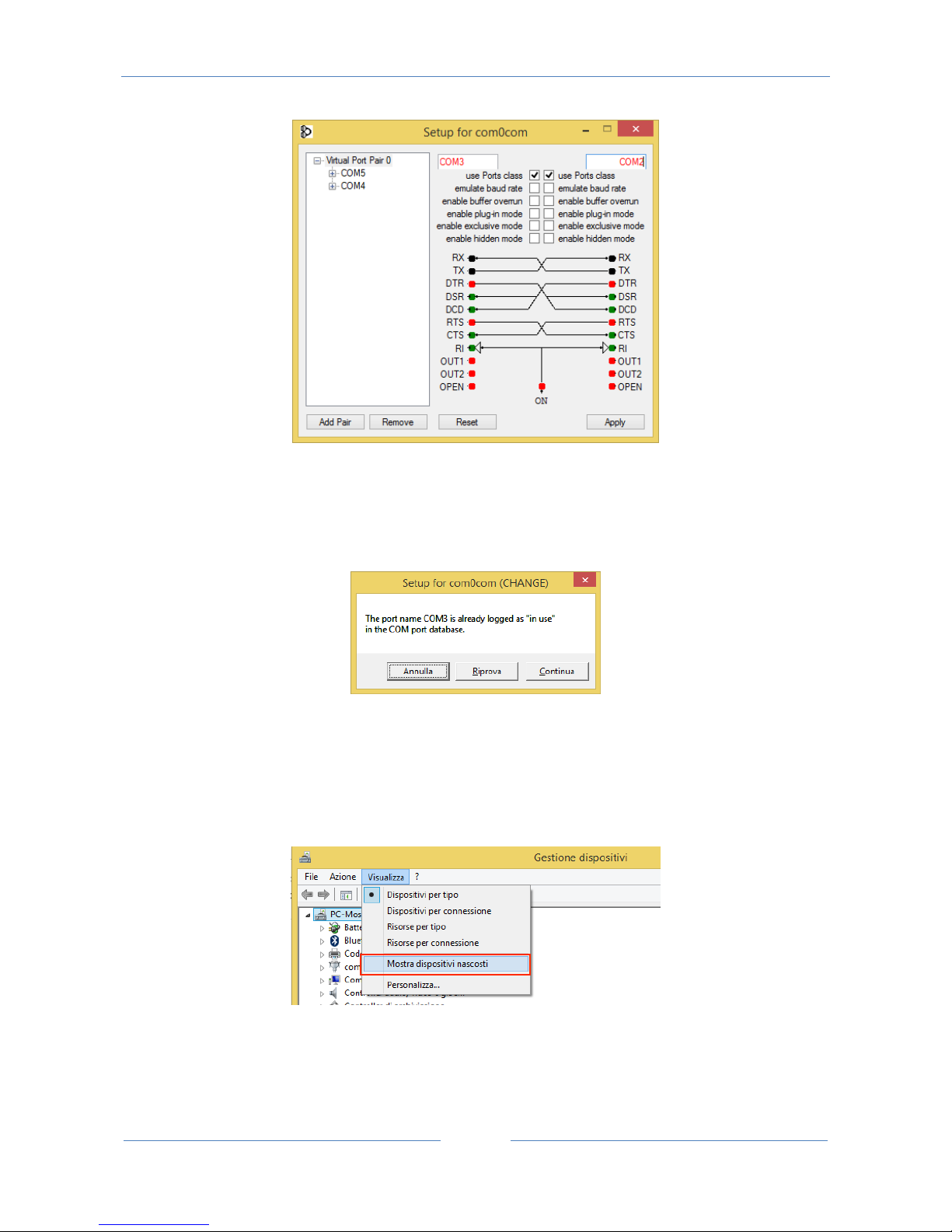
The com0com setup window will open:
Now change COM5 to COM3 and COM4 to COM2 Then click “Apply”:
Page 85
USER MANUAL – Z-KEY
85
Sometimes the COM can be marked as “in use”:
If you need to use this COM number Click on “Continue”, then go to the device manager.
We must uncheck the “in use” flag by uninstalling the port. Because the port now is not connected click on
“Show hidden peripherals”:
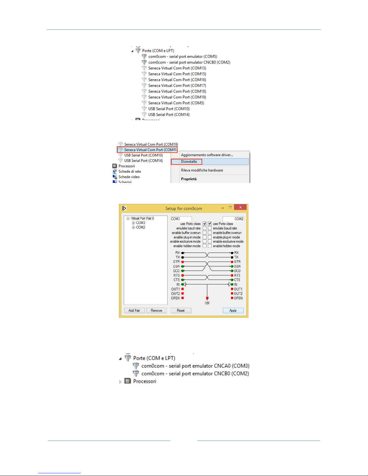
Now all the Ports that are not in use are displayed in transparent (also our COM3):
Page 86
USER MANUAL – Z-KEY
86
Now select the COM3 port and click on “Uninstall”:
Now the COM3 is free and we can use it on the com0com setup:
Then Click on “Apply”, Now the COM3, COM2 pair is created:
WARNING!
Seneca to ethernet connector use always the right port in the com0com Setup (in our case COM2)
Page 87

USER MANUAL – Z-KEY
87
Page 88

USER MANUAL – Z-KEY
88
14. THE CUSTOM WEBSERVER
A custom webserver can be loaded into a microSD card, copy the html pages to the /web directory.
Launch the custom webserver by typing:
http://192.168.90.101/index.html
where 192.168.90.101 is the default ip address.
Demo templates can be freely downloaded from:
http://www.seneca.it/products/z-key
Page 89
USER MANUAL – Z-KEY
89
15. ACCESSING THE Z-KEY FROM INTERNET
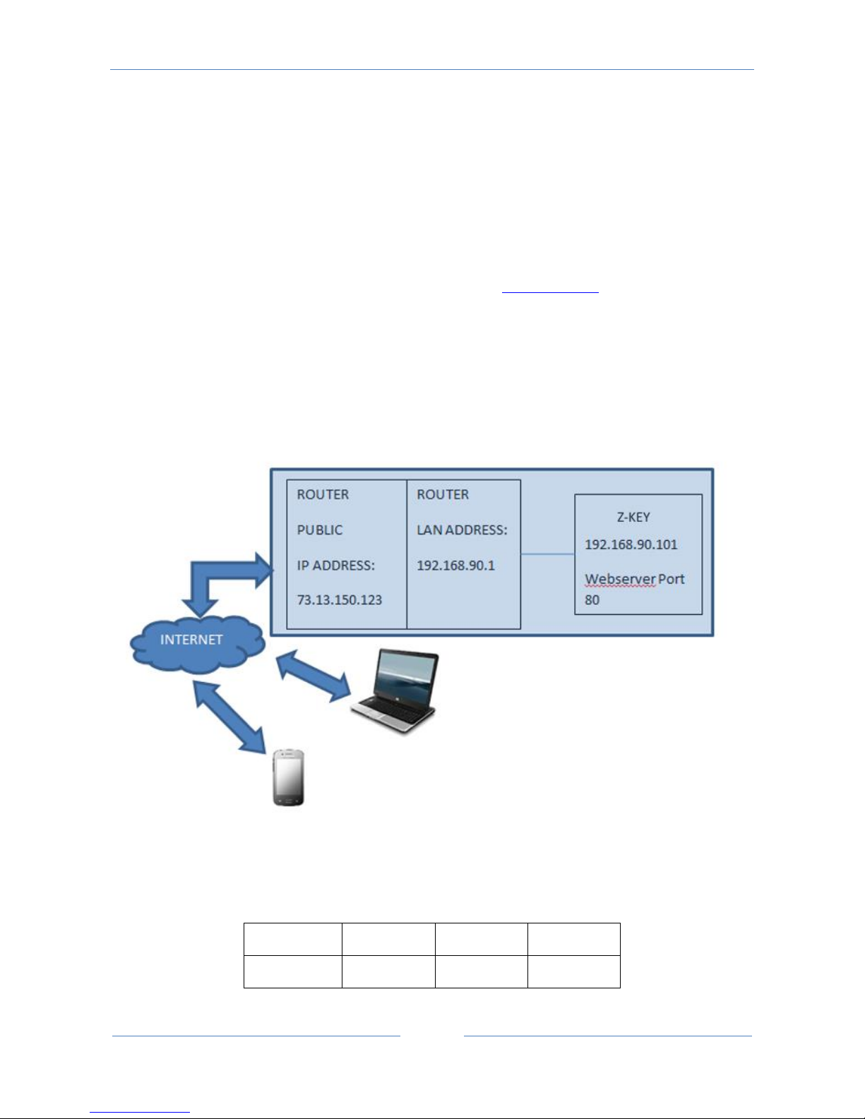
Using a static public ip address it’s possible to configure the router for accessing Z-KEY from internet.
This operation it’s known as “Virtual server “or “Port forwarding” refers to your Router documentation for
more info.
The Ip address of your internet connection must have a static public ip address, if your public ip address
isn’t static you can obtain-it by using a Dynamic DNS like Dyndns (http://dyn.com/).
Take a look to this example:
The Router IP address is 192.168.1.1 and the Z-KEY device address is 192.168.1.101 with the Webserver on
port 80.
For example the Router Public IP address is 73.13.150.123.
Now we must open the port 80 on the router and forwarding it to the IP 192.168.90.101:
So the configuration on the router must be:
IP ADDRESS
PRIVATE PORT
PUBLIC PORT
PROTOCOL
192.168.1.101
80
8080
UDP/TCP
Page 90

USER MANUAL – Z-KEY
90
With this Virtual Server entry, all Internet traffic on Port 8080 with ip address 73.13.150.123 will be
redirected to Z-KEY webserver on port 80 at IP Address 192.168.1.101.
So for accessing to the Z-KEY Webserver using a browser you must enter
http://73.13.150.123/maintenance/index.html:8080
A similar configuration can be used for Modbus TCP-IP access:
IP ADDRESS
PRIVATE PORT
PUBLIC PORT
PROTOCOL
192.168.1.101
502
502
UDP/TCP
Page 91

USER MANUAL – Z-KEY
91
16. THE KIT-USB
The KIT-USB can be obtained from Seneca (can be bought also from the E-commerce Website
www.seneca.it )
The kit contain:
A CD with the Easy Setup software (that contain the USB drivers)
A standard mini USB Cable
A standard micro USB Cable
The Easy Setup software can also be freely downloaded from the website: www.seneca.it
17. THE RS232 DB9 CABLE
The RS232 DB9 CABLE can be obtained from Seneca (can be bought also from the E-commerce Website
www.seneca.it ) for connection between Z-KEY to a DB9 RS232 device.
Page 92

USER MANUAL – Z-KEY
92
18. WINDOWS USB DRIVERS INSTALLATION
The drivers are compatible with the following operating systems:
Windows xp (32 bits)
Windows xp (64 bits)
Windows 7 (32 bits)
Windows 7 (64 bits)
Windows 8 (32 bits) (*)
Windows 8 (64 bits) (*)
Windows 8.1 (32 bits) (*)
Windows 8.1 (64 bits) (*)
Windows 10 (32 bits) (*)
Windows 10 (64 bits) (*)
(*) = From software Easy Setup revision 3.53 or newer.
For installing the USB drivers follow this procedure:
Install the Easy Setup software from the USB KIT CD (see chapter 16) or from the Seneca website
At the end of the installation confirm the USB drivers installation, click on “install the driver software”:
Power up the Z-KEY and connect the USB to the PC, the new hardware it’s detected:
Page 93

USER MANUAL – Z-KEY
93
Now the device it’s connected to the PC.
The operation is performed only the first time that you connect the device.
Page 94

USER MANUAL – Z-KEY
94
19. Firmware Update
Z-Key support the firmware update from webserver, FTP server and microSD card.
Last firmware can be downloaded from:
http://www.seneca.it/products/z-key
19.1. Firmware Update from Webserver
For update the Z-KEY firmware go to the Firmware Update section on the Webserver, select the .bin
firmware then click on “Send new firmware update selected”.
At the end of the file transfer the Z-KEY will switch ON all the red leds and start to program the firmware to
the internal flash (takes about 30 seconds). At the end the Z-KEY will reboot with the new firmware.
WARNING!
Don’t power down the Z-KEY when the update firmware procedure is started!
19.2. Firmware Update from FTP server
For update the Z-KEY firmware from FTP server you must insert a microSD card formatted with fat16 or
fat32 filesystem.
Copy the file “zkey.bin” with the new firmware to the root.
At the end of the file transfer the Z-KEY will switch ON all the red leds and start to program the firmware to
the internal flash (takes about 30 seconds). At the end the Z-KEY will reboot with the new firmware.
WARNING!
Don’t power down the Z-KEY when the update firmware procedure is started!
19.3. Firmware Update from microSD card
For updating the firmware from the microSD card follow the procedure:
Switch OFF Z-KEY
Copy in the microSD root the “zkey.bin” firmware file
Insert the microSD card in the Z-KEY
Switch ON Z-KEY
Page 95
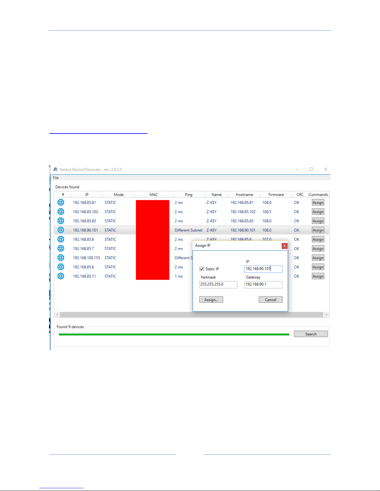
USER MANUAL – Z-KEY
95
Now the Z-KEY will switch ON all the red leds and starts to program the firmware to the internal flash
(takes about 30 seconds). At the end, the Z-KEY will reboot with the new firmware.
The file “zkey.bin” will be automatically deleted from the microSD card
20. Seneca Discovery Device
The Seneca Discovery Device Tool is available for free from:
http://www.seneca.it/products/z-key
With this Tool you can search Z-KEY devices (and others Seneca Device) and change the actual IP
configuration also if your PC has a different subnet.
WARNING!
For Security Reasons you can disable the IP change functionality from the Webserver “Setup” page.
21. Easy Setup APP for Android
Using an OTG Cable and an Android Device With OTG capability you can use Easy Setup App for change the
IP configuration directly from the USB connector.
Page 96

USER MANUAL – Z-KEY
96
For more info go to the and search for the “Seneca Easy Setup APP” icon
.
The OTG Cable can be buy directly from www.seneca.it :
22. CGI (common gateway interface) command
When Z-KEY is configured in Gateway mode it’s possible to read tags values using CGI (Common Gateway
Interface) line commands.
The cgi syntax is (where 192.168.90.101 is the Z-KEY ip address and N is the TAG page to read):
http://192.168.90.101/index.cgi?page=N
N can be from 1 to 10, every page contain 50 tag values.
For example for obtain the first 50 tags the cgi can be:
http://192.168.90.101/index.cgi?page=1
the response is:
NAME: RTU name
FW: Firmware revision
DHCP: activated or not
IP: Actual IP address
NET: Network mask
GW: Gateway address.
MAC: MAC address.
MODE_NR: the actual mode:
0 = "MODBUS BRIDGE ON PORT#1"
1 ="MODBUS BRIDGE ON PORT#2",
Page 97

USER MANUAL – Z-KEY
97
2 = "MODBUS BRIDGE ON PORT#1 AND PORT#2"
3 = "MODBUS GATEWAY PORT#1 AND PORT#2 MASTER"
4 = “MODBUS GATEWAY PORT#1 MASTER AND PORT#2 SLAVE"
5 = "MODBUS GATEWAY PORT#1 SLAVE AND PORT#2 MASTER"
6 = “MODBUS GATEWAY PORT#1 AND PORT#2 SLAVE"
7 = "REMOTE SERIAL COM ON PORT#1"
8 = "REMOTE SERIAL COM ON PORT#2"
ELEMENTS NUMBER: Tags number in this call.
After this begin the Tag values:
TAGNAME: Tag name
TAGADDRESS: Tag Modbus address
TAGFORMAT: Data format
TAGVALUE: Tag value
TAGSTATUS: FAIL or OK
For example a response is:
Z-KEY
4100
Disabled
192.168.85.104
255.255.255.0
192.168.85.1
c8-f9-81-0c-00-26
3
50
Page 98

USER MANUAL – Z-KEY
98
TAG1
40001
UINT16
50
OK
TAG2
40002
UINT16
1000
OK
TAG3
40003
UINT16
50
OK
TAG4
40005
UINT16
0
OK
TAG5
40007
UINT16
40
FAIL
TAG6
40008
Page 99

USER MANUAL – Z-KEY
99
UINT16
0
OK
[…]
40057
FP LSW
0.000000
FAIL
 Loading...