

Page 1
SENECA s.r.l.
(Other)
This document is property of SENECA srl. Duplication and reproduction of its are forbidden
(though partial), if not authorized. Contents of present documentation refers to products and
technologies described in it. Though we strive for reach perfection continually, all technical data
contained in this document may be modified or added due to technical and commercial needs;
it’s impossible eliminate mismatches and discordances completely. Contents of present
documentation is anyhow subjected to periodical revision. If you have any questions don’t
hesitate to contact our structure or to write us to e-mail addresses as above mentioned.
USER MANUAL
Z-GPRS2-SEAL
Z-LOGGER-SEAL
Z-GPRS2-SEAL
Multi-protocol Datalogger/RTU with GSM/GPRS modem and embedded I/O
Multi-protocol Datalogger/RTU with embedded I/O
Via Austria 26, PADOVA – ITALY
Tel. +39.049.8705355 – 8705359 Fax. +39.049.8706287
Web site: www.seneca.it
Customer service: supporto@seneca.it (IT), support@seneca.it
(Other)
Commercial information: commerciale@seneca.it (IT), sales@seneca.it
Z-LOGGER
MI003574_EN

USER MANUAL – Z-GPRS2-SEAL / Z-LOGGER-SEAL
2
Date
Version
Changes
23/04/14
1
First Revision
15/05/14
2
Modified the remote firmware and configuration update
file names.
Added new SMS commands.
Added the Syslog “week rotation”.
Added chapters: Fw update, Configuration update and
Troubleshooting.
21/05/14
3
Changed chapters Local and remote firmware and
configuration update.
Added chapter Extended Phonebook
31/10/14
4
Changed update remote FW/CFG/PHONEBOOK chapters
Added Modbus TCP-IP Server commands
Changed USB drivers chapter (now are signed)
10/02/15
5
http post available only with a GPRS connection

USER MANUAL – Z-GPRS2-SEAL / Z-LOGGER-SEAL
3
SENECA Z-GPRS2 / Z-LOGGER ..................................................................................... 11
PRELIMINARY INFORMATION ........................................................................................ 11
1. CHARACTERISTICS .................................................................................................. 13
1.1. Z-GPRS2 Model characteristics ......................................................................................................................13
1.2. Z-LOGGER Model characteristics ...................................................................................................................14
1.3. Technical Specifications ................................................................................................................................14
1.4. Digital Inputs .................................................................................................................................................14
1.5. Digital outputs ..............................................................................................................................................15
1.6. Analog Inputs ................................................................................................................................................15
1.7. Communication Ports....................................................................................................................................15
1.8. Storage units .................................................................................................................................................16
1.9. Power supply ................................................................................................................................................16
1.10. Environmental conditions .............................................................................................................................16
1.11. Regulations ...................................................................................................................................................16
1.12. Case specifications ........................................................................................................................................17
1.13. Insulation ......................................................................................................................................................17
2. CONNECTIONS .......................................................................................................... 18
2.1. Power supply connections ............................................................................................................................18
2.2. Analog input connections ..............................................................................................................................18
2.3. Auxiliary voltage connections .......................................................................................................................18

USER MANUAL – Z-GPRS2-SEAL / Z-LOGGER-SEAL
4
2.4. Serial communication RS485 ports connections ............................................................................................19
2.5. Digital outputs connections ..........................................................................................................................20
2.6. Digital inputs connections .............................................................................................................................20
3. SIGNAL LEDS ............................................................................................................ 21
3.1. Z-GPRS2 leds .................................................................................................................................................21
3.2. Z-Logger leds .................................................................................................................................................22
4. DEVICES OVERVIEW ................................................................................................ 24
5. SWITCH ON, SWITCH OFF AND FORCED SWITCH OFF OF Z-GPRS2/Z-LOGGER
25
6. SUPPORTED SIM CARDS (Z-GPRS2 ONLY) ........................................................... 26
7. GSM SIGNAL (Z-GPRS2 ONLY) ................................................................................ 27
8. BACKUP BATTERY ................................................................................................... 29
9. USB DRIVER INSTALLATION ON MICROSOFT WINDOWS™ OPERATING
SYSTEMS .......................................................................................................................... 29
9.1. Installing the USB driver on Windows XP™, Windows Vista™ , Windows 7™, Windows 8™ and Windows
8.1™ 30
10. SEAL (SENECA ADVANCED LANGUAGE) .......................................................... 30
10.1. SEAL Overview ..............................................................................................................................................31
10.2. Program Execution in the Graph Panel ..........................................................................................................32
10.3. How SEAL works............................................................................................................................................32
11. THE SEAL MENU BAR ........................................................................................... 36
11.1. Menu File ......................................................................................................................................................36
11.2. Menu Edit .....................................................................................................................................................36
11.3. Menu Project Project Settings .......................................................................................................................37
11.4. Groups, Profiles and Users ............................................................................................................................38

USER MANUAL – Z-GPRS2-SEAL / Z-LOGGER-SEAL
5
11.5. Menu Project: Users ......................................................................................................................................44
11.6. Menu Project: User – Add User .....................................................................................................................45
11.7. Menu Project: User Groups ...........................................................................................................................45
11.8. Menu RTU: Connection .................................................................................................................................46
11.9. Menu RTU Test Monitor ................................................................................................................................47
11.10. Menu RTU: FW Update .............................................................................................................................52
11.11. Menu RTU: Open project from RTU ..........................................................................................................53
11.12. Menu RTU: Convert Phonebook CSV .........................................................................................................53
11.13. Menu Build: Generate ...............................................................................................................................53
11.14. Menu Build: Generate and send to RTU ....................................................................................................54
11.15. Menu Window: Build Output ....................................................................................................................55
11.16. Menu Window: Edit Form .........................................................................................................................55
11.17. Menu Window: Logs .................................................................................................................................55
11.18. Menu Window: Default Layout .................................................................................................................56
11.19. Menu Window: Tile Horizontal .................................................................................................................56
11.20. Menu Window: Tile Vertical .....................................................................................................................56
11.21. Menu help ................................................................................................................................................56
12. THE SEAL ICON MENU .......................................................................................... 56
12.1. GSM/GPRS Modem .......................................................................................................................................57
12.2. Ethernet Services ..........................................................................................................................................59
12.3. Real Time Clock .............................................................................................................................................68
12.4. Cloud.............................................................................................................................................................72
12.5. Modbus RTU and Modbus TCP-IP Master Window .......................................................................................76
12.6. Data Logger Window .....................................................................................................................................84
12.7. Application Window .....................................................................................................................................89
12.8. System Management Configuration Window ................................................................................................98

USER MANUAL – Z-GPRS2-SEAL / Z-LOGGER-SEAL
6
12.9. Analog Input Configuration Window .............................................................................................................99
12.10. Digital Input Configuration Window ....................................................................................................... 102
12.11. Digital Input Configuration Window ....................................................................................................... 103
12.12. Digital Output Configuration Window..................................................................................................... 107
13. EVENT BLOCKS ................................................................................................... 108
13.1. Event Block SYS_POW_DOWN: System Management Power Down ............................................................ 108
13.2. Event Block SYS_LOW_BAT: System Management Battery Control ............................................................. 109
13.3. Event Block AIN_MAX: Analog Input Maximum Threshold Event ................................................................ 109
13.4. Event Block AIN_HIGH: Analog Input High Threshold Event ........................................................................ 109
13.5. Event Block AIN_LOW: Analog Input Low Threshold Event ......................................................................... 109
13.6. Event Block AIN_LOW: Analog Input Low Threshold Event ......................................................................... 110
13.7. Event Block RTC_DAYLIGHT: Daylight Event ................................................................................................ 110
13.8. Event Block RTC_DAWN: Sunrise Event ....................................................................................................... 110
13.9. Event Block RTC_DUSK: Sunset Event .......................................................................................................... 110
13.10. Event Block RTC_SYNC: Time Synchronization Error Event ...................................................................... 111
13.11. Event Block DIN_ON: Not filtered Digital Input ON Event ....................................................................... 111
13.12. Event Block DIN_ALM: Filtered Digital Input Event ................................................................................. 111
13.13. Event Block DIN_TOT_ALM: Total Counter Event .................................................................................... 111
13.14. Event Block DIN_CNT_ALM: Partial Counter Event .................................................................................. 112
13.15. Event Block DIN_WORK_ALM: Work Time Event .................................................................................... 112
13.16. Event Block DIN_DELTA_ALM: Delta Counter Event ................................................................................ 112
13.17. Event Block DIN_TOT_RESET: Total Counter Reset Event ........................................................................ 112
13.18. Event Block DIN_CNT_RESET: Partial Counter Reset Event ...................................................................... 113
14. VARIABLE BLOCKS............................................................................................. 113
14.1. Variable Block SYS_POW: Main Power Variable .......................................................................................... 113
14.2. Variable Block SYS_VBAT: Main Power Variable ......................................................................................... 113

USER MANUAL – Z-GPRS2-SEAL / Z-LOGGER-SEAL
7
14.3. Variable Block AIN_VAL : Analog Input Datalogger Sampled Value ............................................................. 114
14.4. Variable Block AIN_AVG : Analog Input Datalogger Average Value ............................................................. 114
14.5. Variable Block AIN_MIN : Analog Input Datalogger Minimum Value........................................................... 114
14.6. Variable Block AIN_MAX : Analog Input Datalogger Maximum Value ......................................................... 115
14.7. Variable Block DIN_STS: Digital Input Value Sampled Variable ................................................................... 115
14.8. Variable Block DIN_TOT: Total Counter Value Sampled Variable ................................................................ 116
14.9. Variable Block DIN_CNT: Partial Counter Value Sampled Variable .............................................................. 116
14.10. Variable Block DOUT_STS: Digital Output Value Sampled Variable ......................................................... 116
14.11. Variable Block GSM_DBM: GSM signal field Value Sampled Variable ..................................................... 117
14.12. Variable Block MODBUS IN/OUT: Modbus Value Variable ...................................................................... 117
15. BLOCKS FUNCTIONS .......................................................................................... 118
15.1. Function Block BIT: STATE BITS TEST FUNCTION .......................................................................................... 118
15.2. Function Block BIT_AND: AND REGISTERS STATE BITS TEST FUNCTION ....................................................... 119
15.3. Function Block BIT_AND: OR REGISTERS STATE BITS TEST FUNCTION ......................................................... 121
15.4. Function Block CMP: ANALOG DIFFERENCE COMPARE FUNCTION .............................................................. 122
15.5. Function Block THR: ANALOG THRESHOLD COMPARE WITH HYSTERESIS FUNCTION .................................. 123
15.6. Function Block CPY: ANALOG VARIABLE COPY TO ANOTHER VARIABLE WITH TRIGGER FUNCTION ............ 124
15.7. Function Block LST: SCALED ANALOG INPUTS LESS THAN COMPARE FUNCTION ......................................... 125
15.8. Function Block GRT: SCALED ANALOG INPUTS GREATER THAN COMPARE FUNCTION................................. 126
15.9. Function Block POW: ANALOG INPUTS MULTIPLICATION GREATER THAN COMPARE FUNCTION ................ 127
15.10. Function Block AVG: ANALOG AVERAGE GREATER THAN COMPARE FUNCTION ..................................... 128
15.11. Function Block DEV: ANALOG AVERAGE ABSOLUTE DIFFERENCE GREATER THAN COMPARE FUNCTION 129
15.12. Function Block MAD: ANALOG AVERAGE ABSOLUTE DIFFERENCE COMPARE WITH CHANNEL DETECT
FUNCTION 130
16. BLOCKS CONTROLS ........................................................................................... 132
16.1. Control Block EC: EVENT LOGIC CONTROL ................................................................................................... 132

USER MANUAL – Z-GPRS2-SEAL / Z-LOGGER-SEAL
8
16.2. Control Block EC setup configuration .......................................................................................................... 135
16.3. Control Block MSG: Event notify Message................................................................................................... 138
16.4. Control Block CAL: Calendar Block Control .................................................................................................. 139
16.5. Control Block TRG: Timed Trigger Block Control .......................................................................................... 141
16.6. Control Block TMR: Timer Control Block Control ......................................................................................... 143
17. BLOCKS ACTIONS DOUTS ................................................................................. 146
17.1. Action Block DOUTS RESET: Reset digitals output 1 and output 2 action ..................................................... 146
17.2. Action Block DOUTS SET: Set digitals output 1 and output 2 action ............................................................ 147
17.3. Action Block DOUTS TOGGLE: Toggle digitals output 1 and output 2 action ................................................ 147
17.4. Action Block DOUTS RES1_SET2: Reset digital output 1 and Set digital output 2 action .............................. 148
17.5. Action Block DOUTS SET1_RES2: Set digital output 1 and Reset digital output 2 action .............................. 148
17.6. Action Block DOUT RESET: Reset digital output action ................................................................................ 149
17.7. Action Block DOUT SET: Set digital output action ........................................................................................ 149
17.8. Action Block DOUT TOGGLE: Toggle digital output action ........................................................................... 150
17.9. Action Block PULSE_RESET: Pulse Reset output action ................................................................................ 150
17.10. Action Block PULSE_SET: Pulse Set output action ................................................................................... 151
17.11. Action Block PULSE_TOGGLE: Pulse Toggle output action ....................................................................... 151
18. BLOCKS ACTIONS MODBUS .............................................................................. 152
18.1. Action Block BIT_CLR: Modbus Register Bit Clear action ............................................................................. 152
18.2. Action Block BIT_SET: Modbus Register Bit Set action................................................................................. 152
18.3. Action Block DEC: Modbus Register Decrement Action ............................................................................... 153
18.4. Action Block INC: Modbus Register Increment Action ................................................................................. 153
18.5. Action Block RES: Modbus Register Reset Action ........................................................................................ 154
18.6. Action Block COPY: Modbus Register Copy Action ...................................................................................... 154
19. LOCAL FIRMWARE UPDATE .............................................................................. 154

USER MANUAL – Z-GPRS2-SEAL / Z-LOGGER-SEAL
9
19.1. Firmware update via USB ............................................................................................................................ 155
19.2. Firmware update via microSD card (without using a PC) ............................................................................. 155
20. REMOTE FIRMWARE UPDATE ........................................................................... 156
20.1. Remote firmware update by Ethernet connection (FTP Server activated) ................................................... 156
20.2. Remote firmware update by Ethernet connection (Modbus TCP-IP Server activated) ................................. 156
20.3. Remote firmware update by GPRS connection ............................................................................................ 157
21. LOCAL CONFIGURATION UPDATE .................................................................... 159
21.1. Local configuration update by SD card ........................................................................................................ 159
22. REMOTE CONFIGURATION UPDATE ................................................................. 159
22.1. Remote configuration update by Ethernet connection (FTP Server enabled) .............................................. 159
22.2. Remote configuration update by Ethernet connection (Modbus TCP-IP Server enabled) ............................ 160
22.3. Remote configuration update by GPRS connection ..................................................................................... 161
23. EXTENDED PHONEBOOK INTO MICROSD FOR RING COMMAND ................. 162
23.1. Creation of an Extended Phonebook File .................................................................................................... 162
23.2. Update of an Extended Phonebook File Via Ethernet .................................................................................. 163
23.3. Update of an Extended Phonebook File Via Gprs ........................................................................................ 163
24. SUPPORTED SMS COMMANDS (ONLY Z-GPRS2) ............................................ 163
24.1. Set the Telephone Sms Character Alphabet ................................................................................................ 163
24.2. List of Supported Sms Commands ............................................................................................................... 164
25. SUPPORTED MODBUS TCP-IP COMMANDS (ONLY BY ETHERNET) ............. 169
26. SEAL PROGRAM EXAMPLES ............................................................................. 170
26.1. Send Alert SMS on digital input 1 and copy alert state on output 1 ............................................................ 170
26.2. Temperature Control with Logger and Alerts .............................................................................................. 172
26.3. Remote inputs to remote outputs copy by ethernet connection ................................................................. 174

USER MANUAL – Z-GPRS2-SEAL / Z-LOGGER-SEAL
10
27. TROUBLESHOOTING........................................................................................... 176

USER MANUAL – Z-GPRS2-SEAL / Z-LOGGER-SEAL
11
Seneca Z-GPRS2 / Z-LOGGER
PRELIMINARY INFORMATION
CAUTION!
Contact your telephone provider for information on GSM and GPRS service costs. It is best to
quantify log and SMS costs before setting up and installing Z-GPRS2.
The use of Z-GPRS2 in data roaming (for example, abroad with an Italian SIM card) may
generate unexpected costs. Contact your telephone provider for further information.
IN NO CASE MAY SENECA OR ITS SUPPLIERS BE HELD LIABLE FOR ANY INCOMING DATA OR
PROFIT LOSSES DUE TO INDIRECT, CONSEQUENTIAL OR INCIDENTAL CAUSES (INCLUDING
NEGLIGENCE) CONNECTED WITH THE USE OR INABILITY TO USE Z-GPRS2 AND Z-LOGGER, EVEN IF
SENECA WAS INFORMED OF THE POTENTIAL OF THESE DAMAGES.
SENECA, ITS SUBSIDIARIES OR AFFILIATES OR GROUP PARTNERS OR DISTRIBUTORS AND SENECA
DEALERS DO NOT GUARANTEE THAT THE FUNCTIONS FAITHFULLY MEET THE EXPECTATIONS AND
THAT Z-GPRS2 AND/OR Z-LOGGER, THEIR FIRMWARE AND SOFTWARE ARE FREE OF ERRORS OR
FUNCTION UNINTERRUPTEDLY.
SENECA HAS TAKEN THE UTMOST CARE AND CAUTION IN DRAFTING THIS MANUAL. HOWEVER,
IT MAY CONTAIN ERRORS OR OMISSIONS. SENECA SRL RESERVES THE RIGHT TO MODIFY
AND/OR VARY PARTS OF THIS MANUAL TO CORRECT ERRORS OR TO ADJUST TO PRODUCT
FEATURE CHANGES WITHOUT ANY PRIOR NOTICE.
CAUTION!
-Contact your telephone service provider for GSM and GPRS service costs especially when using
Z-GPRS2 with a sim issued by a country other than the one in which it is used (international
roaming).
-It is best to estimate telephone costs before setting up Z-GPRS2.
-The cost of each SMS is set by the telephone service provider.
-GPRS send/receive costs can be tied to Kbytes sent/received, a monthly ceiling included in a
package or GPRS connection time. Contact your telephone service provider for further
information.

USER MANUAL – Z-GPRS2-SEAL / Z-LOGGER-SEAL
12
-For GPRS connections whose costs is associated with connection time, please remember that
communications are active for an amount of time that depends on the number of log rows to be
sent. Typically, a 2 Kbyte data log takes about 10-15 seconds to be sent in addition to the time
necessary to establish the connection (from 5 to 30 seconds) and the time due to any server login
attempts.
-Check the data quantity sent via GPRS and SMS before using Z-GPRS2.
Please remember that mobile phone service providers also consider the entire communication
that permits file transmission (and thus data transmission overhead, the number of connection
attempts, etc.) and not just the dimensions as data traffic in each GPRS transaction.

USER MANUAL – Z-GPRS2-SEAL / Z-LOGGER-SEAL
13
1. CHARACTERISTICS
1.1. Z-GPRS2 Model characteristics
Z-GPRS2 is a multi-protocol programmable datalogger/RTU with GSM/GPRS modem and
embedded IO.
Supply voltage 11..40 Vdc; 19..28 Vac max 6.5 W
2 AAA 1.2 V, NiMh rechargeable backup batteries
GSM/GPRS Quad-Band modem
500 Vac insulation between remaining circuit power
Quick installation on DIN 46277 guide
Status indication LED: digital inputs, digital outputs, Ethernet, GSM, RS485, Power,
microSD
NR 4 digital inputs
NR 2 16-bit voltage/current programmable analog inputs
NR 2 relay digital outputs
10/100 Mbps frontal Ethernet RJ45
NR 2 RS484 ports
1 type B miniUSB port for settings
MicroSD support (microSD or microSDHC max 32 Gb)
NR4 32 bits max 30 Hz totalizers
NR4 32 bits max 30 Hz resettable counters
Possibility of expanding the number of I/O via Modbus TCP-IP or Modbus RTU
Maximum number of channels on datalogger: 128 (of which 100 via Modbus RTU/TCP-IP)
Supported system protocols via GSM: SMS, voice calls (zero cost command)
Supported system protocols via GPRS: FTP client, SMTP client, SMTPS client
Supported system protocols via Ethernet port: FTP client, FTP server*, SMTP client,
ModBUS TCP-IP Server
Protocol on RS485: Modbus RTU Master
Webserver* via Ethernet port
128 KB RAM memory
Memory expansion up to 32 GigaBytes with micro SD
32 bits ARM processor
Real Time multitasking operating system
Firmware update via USB / microSD/or by remote connection
*= Ethernet services cannot be used simultaneously

USER MANUAL – Z-GPRS2-SEAL / Z-LOGGER-SEAL
14
Channels number
4
1.2. Z-LOGGER Model characteristics
Z-LOGGER is a multi-protocol programmable datalogger/RTU with embedded IO.
Supply voltage 11..40 Vdc; 19..28 Vac max 6.5 W
NR 2 AAA 1.2 V, NiMh rechargeable backup batteries
500 Vac insulation between remaining circuit power
Quick installation on DIN 46277 guide
Status indication LED: digital inputs, digital outputs, Ethernet, RS485, Power, microSD
NR 4 digital inputs
NR 2 16-bit voltage/current programmable analog inputs
NR 2 clean contact relay digital outputs
10/100 Mbps frontal Ethernet RJ45
NR 2 RS484 ports
1 type B miniUSB port for settings
MicroSD support (microSD or microSDHC max 32 Gb)
NR4 32 bits max 30 Hz totalizers
NR4 32 bits max 30 Hz resettable counters
Possibility of expanding the number of digital or analog I/O via Modbus TCP-IP or
Modbus RTU
Maximum number of channels on datalogger: 128 (of which 100 via Modbus RTU/TCP-IP)
Supported system protocols via Ethernet port: FTP client, FTP server*, SMTP client,
ModBUS TCP-IP Server
System protocol on RS485: Modbus RTU Master
Webserver* via Ethernet port
128 KB RAM memory
Memory expansion up to 32 GB with micro SD
32 bits ARM processor
Real Time multitasking operating system
Firmware update via USB / microSD or by remote connection
*= Ethernet services cannot be used simultaneously
1.3. Technical Specifications
1.4. Digital Inputs

15
Input type
PNP, NPN configurable.
Voltage supply
12 Vdc
Current supply
20 mA
Maximum frequency
30 Hz
Current consumption
3 mA
Channels number
2
Output type
Relay
Maximum Voltage
250 Vac
Maximum Current
2 A
Channels number
2
Input type
Current / Voltage configurable
Voltage input
0..30V accuracy 0,1% FS
Current input
0..20 mA accuracy 0,1% FS
Input protection
yes, 12Vdc or 25mA
Resolution
16 bits
1.5. Digital outputs
USER MANUAL – Z-GPRS2-SEAL / Z-LOGGER-SEAL
1.6. Analog Inputs
1.7. Communication Ports

16
RS 485 #1
Port #1, on IDC10 connector
RS 485 #2
Port #2, terminals M10/M11/M12
Ethernet
10/100 Mbit, RJ45 with autoswitch
USB mini B
Mini B
Internal Flash
2 Mbytes for configuration and for logger
Buffer
MicroSD
microSD and microSDHC, max 32 GB
(supplied with 1, 2 or 4GBytes microSD)
Voltage
11...40 Vdc; 19…28 Vac
Power consumption
6,5 W
Temperature
From -10 to +40 °C
Humidity
30..90% to 40 °C non condensing
Storage temperature
From -20 to +45 °C < 6 months
Protection rating
IP20
1.8. Storage units
USER MANUAL – Z-GPRS2-SEAL / Z-LOGGER-SEAL
1.9. Power supply
1.10. Environmental conditions
1.11. Regulations

USER MANUAL – Z-GPRS2-SEAL / Z-LOGGER-SEAL
17
EN61000-6-4/2002-10
Electromagnetic emission, industrial
environment.
EN61000-6-2/2006-10
Electromagnetic immunity, industrial
environment.
EN 301 511 (only Z-GPRS2)
Harmonized standard for mobile stations in the
GSM
900 and 1800 bands.
EN 301 489-1 (only Z-GPRS2)
ElectroMagnetic Compatibility standard for
radio equipment and services.
EN 301 489-7 (only Z-GPRS2)
Specific (EMC) conditions for mobile radio
equipment
(GSM 900 and 1800).
EN 60950
Safety of information Technology Equipment.
Dimensions and weight
100 x 111 x 35 mm, 280 g
Material
Black PBT
500 Vac
1.12. Case specifications
1.13. Insulation

USER MANUAL – Z-GPRS2-SEAL / Z-LOGGER-SEAL
18
2. CONNECTIONS
2.1. Power supply connections
You can supply DC or AC power to terminals 2-3, in the case of DC power supply is not necessary to
distinguish between the "+" from the "-" cable:
2.2. Analog input connections
The analog input 1 voltage / current is connected to terminal 4 (- sign for the voltage, the current exit) and
6 (+ sign to the voltage, the current incoming).
The analog input 2 voltage / current is connected to terminal 4 (- sign for the voltage, the current exit) and
5 (+ sign to the voltage, the current incoming).
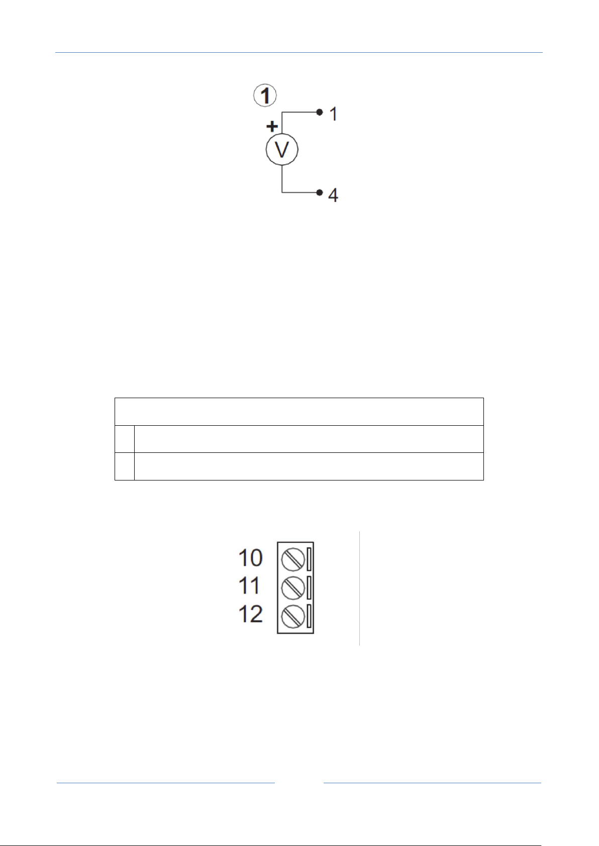
2.3. Auxiliary voltage connections
The device can provide from 12 to 15 VDC (max 40mA) to an external sensor connected to terminals 1 (+)
and 4 (-):
USER MANUAL – Z-GPRS2-SEAL / Z-LOGGER-SEAL
19
SW2 ■ = ON
Rear IDC10 connector, CANopen (not supported)
■
Rear IDC10 connector, RS485
2.4. Serial communication RS485 ports connections
The RS485 port # 1 is connected to the bottom connector "IDC10" for connecting to the Z-BUS Seneca.
WARNING!
In order to use the Z-BUS connector RS485 as you need to move SW2 to "rear IDC10 connector is
485":
The RS485 #2 port is connected to terminal 10-11-12:
10 = GND RS485#2
11 = A RS485#2
12 = B RS485#2
USER MANUAL – Z-GPRS2-SEAL / Z-LOGGER-SEAL
20
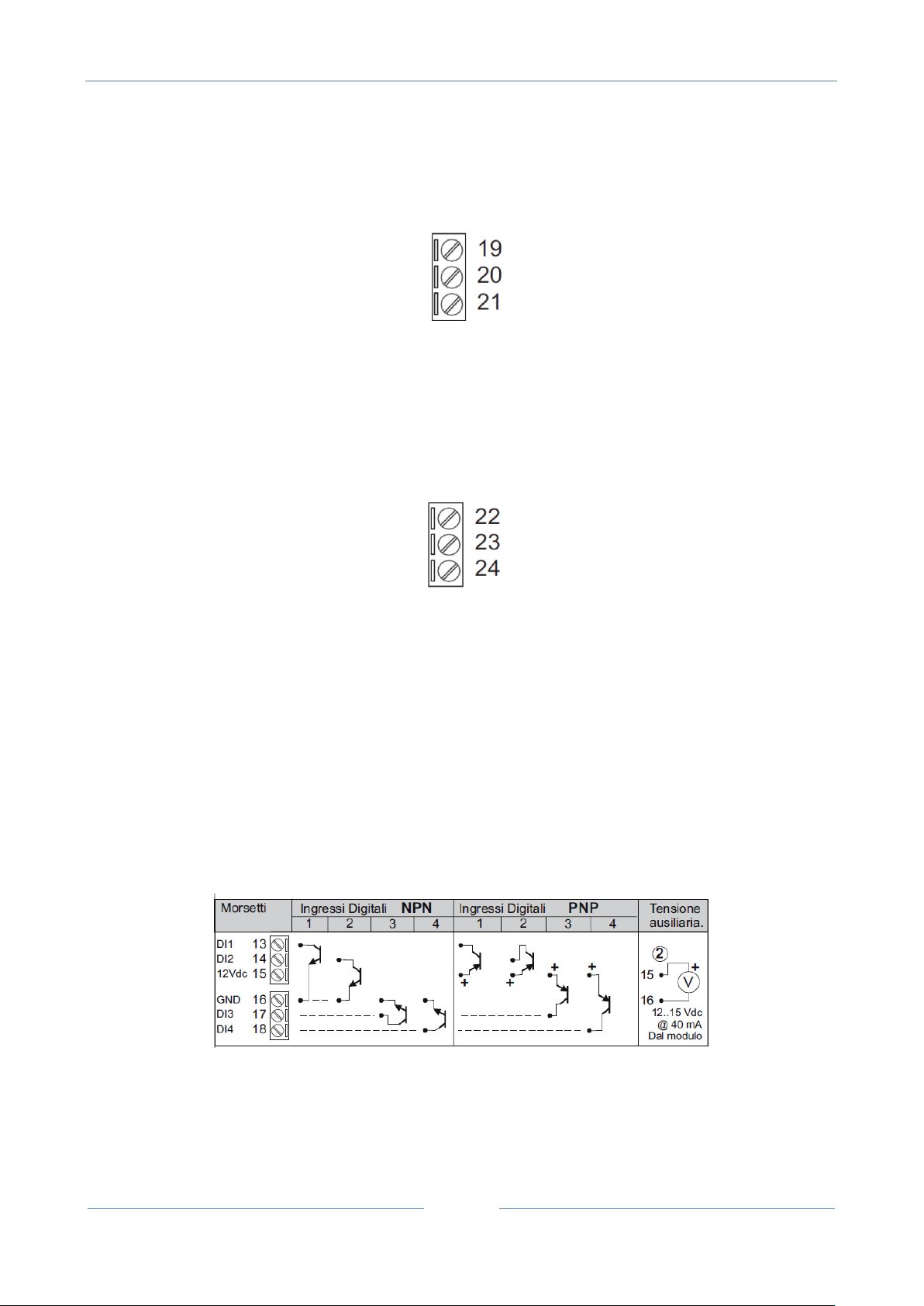
2.5. Digital outputs connections
The output relay is connected between terminals 19-20-21:
19 = Normally open relay #1
21 = Shared relay #1
22 = Normally close relay #1
22 = Normally open relay #2
23 = Shared relay #2
24 = Normally close relay #2
2.6. Digital inputs connections
It’s possible to provide power to an external sensor by terminals 15-16 (max 40mA) .
The inputs can be configured in NPN or PNP mode, see below:
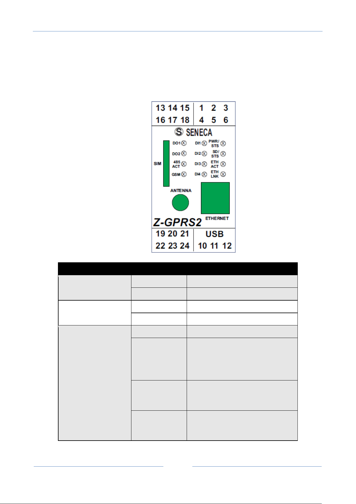
21
LED
STATUS
MEANING
DO1
ON
Digital output, relay energised
OFF
Digital output, relay not energised
DO2
ON
Digital output, relay energised
OFF
Digital output, relay not energised
PWR/ STS
ON
Z-GPRS2 on but log stopped
OFF
Awaiting Boot
SLOW FLASH (3
sec ON and 0.5
OFF)
Log on, normal operations
MEDIUM FLASH
(0.3 sec ON and
0.3 sec OFF)
Backup battery powered, log off
FAST FLASH (0.2
sec ON and 0.2
sec OFF)
Battery charge low, shutting down.
3. SIGNAL LEDS
3.1. Z-GPRS2 leds
USER MANUAL – Z-GPRS2-SEAL / Z-LOGGER-SEAL
.

USER MANUAL – Z-GPRS2-SEAL / Z-LOGGER-SEAL
22
GSM
SLOW FLASH
(about 3 sec)
Registered on GSM/GPRS network
FAST FLASHING
(about 0.5 sec)
Searching GSM/GPRS network
DI1
ON
Digital Input FOUND
OFF
NO digital input
DI2
ON
Digital Input FOUND
OFF
NO digital input
DI3
ON
Digital Input FOUND
OFF
NO digital input
DI4
ON
Digital Input FOUND
OFF
NO digital input
SD/STS
FLASHING
Access to microSD card
485 ACT
FLASHING
Activity on RS485
ETH LNK
FLASHING
Connection on RJ45 on
ETH TRF
FLASHING
Packet transit on Ethernet port
3.2. Z-Logger leds
USER MANUAL – Z-GPRS2-SEAL / Z-LOGGER-SEAL
23
LED
STATUS
MEANING
DO1
ON
Digital output, relay energised
OFF
Digital output, relay not energised
DO2
ON
Digital output, relay energised
OFF
Digital output, relay not energised
PWR/ STS
ON
Z-LOGGER is on but the log is
stopped
OFF
Awaiting Boot
SLOW FLASH (3
sec ON and 0.5
OFF)
Log on, normal operations
MEDIUM FLASH
(0.3 sec ON and
0.3 sec OFF)
Backup battery powered, log off
FAST FLASH (0.2
sec ON and 0.2
sec OFF)
Battery charge low, shutting down.
DI1
ON
Digital Input FOUND
OFF
NO digital input
DI2
ON
Digital Input FOUND
OFF
NO digital input
DI3
ON
Digital Input FOUND
OFF
NO digital input
DI4
ON
Digital Input FOUND
OFF
NO digital input
SD/STS
FLASHING
Access to microSD card
485 ACT
FLASHING
Activity on RS485
ETH LNK
FLASHING
Connection on RJ45 on
ETH TRF
FLASHING
Packet transit on Ethernet port
For further information, see the Z-GPRS2/Z-logger installation manual available for free download at
www.seneca.it in the Z-GPRS2 / Z-Logger section.

USER MANUAL – Z-GPRS2-SEAL / Z-LOGGER-SEAL
24
4. DEVICES OVERVIEW
Z-GPRS2/Z-Logger is equipped with 4 counters and 4 totalizers. Up to a maximum of 30 Hz signals
can be acquired, 4 digital inputs, 2 analog inputs and 2 relay digital outputs.
Z-GPRS2 I/O and remote Modbus RTU or Modbus TCP-IP registers can be logged and sent as a file
in csv format (comma separated values, microsoft excel™ compatible) via ftp or email and saved
on microSD. Z-GPRS2 can also send the last row of the log file via SMS.
Up to 11774 log rows can be saved in the internal flash memory (not to be confused with the
microSD card), If all 100 TAG modbus is activated 2943 log rows can be saved on internal flash. At
the end of available space, Z-GPRS2/Z-Logger overwrites the oldest rows in the memory.
Counter/totalizer inputs and analog inputs can be scaled. The scaled values will be saved in the
log.
4 different alarm thresholds are available for each of the two analog inputs.
An SMS (only for Z-GPRS2) or EMAIL can be sent with a settable text when this alarm trips (max 31
characters). An Http post to a server can be also used (only with GPRS connection).
Other types of alarms concern counters, totalizers, digital input increases, power outage, plumbing
leaks and the hour counter in addition to other alarms that depend on the type of application.
Timers and calendar timers are available to run cyclic or acyclic actions.
Z-GPRS2 recognises and runs a series of commands also via SMS. A set of "FAST" commands can
also be set. These commands can be linked to the text in SMS 0, 1 up to 15.
Z-GPRS2/Z-LOGGER can send log files via FTP, via E-MAIL or via http post (only with GPRS
connection). These files can also be saved on microSD or microSDHC.
All configurations are possible via the SEAL software, available for free download at www.seneca.it
in the download or Z-GPRS2-SEAL / Z-LOGGER-SEAL section.
Z-GPRS2 and Z-Logger includes an address book used to send alarms or logs.
Some typical applications such as string current control on photovoltaic systems, etc. can also be
managed.
A system file (syslog) with events, alarms, errors and commands received can also be logged. Every
Monday at 00:00 the actual syslog is resetted but first the file is renamed for backup purpose into
the microSD.

USER MANUAL – Z-GPRS2-SEAL / Z-LOGGER-SEAL
25
5. SWITCH ON, SWITCH OFF AND FORCED SWITCH OFF OF Z-GPRS2/Z-
LOGGER
Z-GPRS2 and Z- Logger are equipped with back-up batteries to perform programmable actions in
case of blackout.
Switch ON Z-GPRS2/Z-logger :
1 ) Supply power to Z-GPRS2/Z-Logger via screw terminal or via BUS IDC10
2 ) If you need it, connect the USB port to a PC
Switch OFF Z-GPRS2/Z-logger :
1) Unplug the USB port
2) Unplug the Power supply (from terminal or from BUS IDC10 )
3 ) The board performs the planned operations in the event of a blackout and then shuts down
automatically. The procedure can take from 5 seconds to a maximum of 10 minutes.
For more information about the backup batteries , refer to the batteries chapter.
Forced the Switch OFF of Z-GPRS2/Z-logger :
To obtain a fast forced shutdown of Z-GPRS2/Z-Logger, short pins 1 and 4 of the
debug port (for example with a screwdriver or a piece of cable ).
The operation turn off the device immediately without waiting for the execution of any action
programmed in the event of a blackout.
WARNING!
THE FORCED SWITCH OFF PROCEDURE COULD CORRUPT THE MICROSD IF THE DEVICE WAS
WRITING ON IT. TO AVOID MICROSD DATA CORRUPTION BEFORE THIS PROCEDURE UNMOUNT
THE MICORSD WITH THE SEAL SOFTWARE.

USER MANUAL – Z-GPRS2-SEAL / Z-LOGGER-SEAL
26
WARNING!
THE FORCED SHUT DOWN PROCEDURE CAN SEND ALL THE LOG INTO THE INTERNAL FLASH AT
SWITCH ON.
6. SUPPORTED SIM CARDS (Z-GPRS2 ONLY)
Z-GPRS2 supports the following types of SIM CARDS:
Top-up voice SIM CARD
Subscription voice SIM CARD
Data transmission only SIM CARD
"Zero cost" operations can be run only on voice type SIM CARDS, if Z-GPRS2 receive a ring an action can be
made.
For "top-up" SIM CARDS Z-GPRS2 can manage residual credit requesting the amount from the telephone
service provider.
CAUTION!
-Before inserting the SIM CARD in Z-GPRS2, CANCEL ALL MESSAGES ON THE CARD USING A
MOBILE PHONE.
-Before inserting the SIM CARD in Z-GPRS2, CANCEL ALL ADDRESS BOOK CONTACTS ON THE
CARD USING A MOBILE PHONE.
-UMTS SIM CARDS are NOT supported.
-The Product was tested with leading international provider SIM CARDS. However, operations
are not guaranteed with all providers.

USER MANUAL – Z-GPRS2-SEAL / Z-LOGGER-SEAL
27
GSM Signal
GSM signal [dBm]
0 (MINIMUM)
-115
1
-106
2
-97 3 -88 4 -79 5 -70 6 -61
7 (MAXIMUM)
-52
7. GSM SIGNAL (Z-GPRS2 ONLY)
The Z-GPRS2 GSM signal level can be found via SEAL software (in the “test“ section).
To view the GSM signal level, the SIM CARD supplied by the telephone service provider to be used
must be inserted (signal may change radically based on the selected provider).
The field is expressed in DBm where -115 dBm it’s the minimum, -52 dBm it’s the maximum.
This table can be used:
Where 0 it’s the minimum, and 7 it’s maximum.
For correct ftp or email log operations the minimum required field level is 2/7 (please remember
that the signal often fluctuates).
For SMS operations only the minimum required field level is 2/7.
Refer to the following table for signal values:
SIGNAL LEVEL 0 = NO SIGNAL (INSUFFICIENT)
SIGNAL LEVEL 1 = INSUFFICIENT SIGNAL (NOT RELIABLE FOR SMS AND GPRS)
SIGNAL LEVEL 2 = SUFFICIENT SIGNAL (MINIMUM SIGNAL FOR SMS AND GPRS)
SIGNAL LEVEL 3 = RELIABLE SIGNAL (RELIABLE FOR SMS AND GPRS)
SIGNAL LEVEL 4 = GOOD SIGNAL
SIGNAL LEVEL 5 = VERY GOOD SIGNAL

USER MANUAL – Z-GPRS2-SEAL / Z-LOGGER-SEAL
28
SIGNAL LEVEL 6 = OPTIMAL SIGNAL
SIGNAL LEVEL 7 = EXCELLENT SIGNAL
To increase the GSM signal level, Seneca provides various GSM antenna models for Z-GPRS2 to
reach the minimum signal level in most situations.
Visit (www.seneca.it) or refer to the general catalogue or contact Seneca srl for further
information.
CAUTION!
-Insert the SIM card only with Z-GPRS2 off.
-Before inserting the SIM card in Z-GPRS2, delete all SMS on the SIM using a mobile phone
-Wait at least 5 minutes in order for the GSM signal to be correctly read.
CAUTION!
-Contact your telephone service provider for GSM and GPRS service costs especially when using
Z-GPRS2 with a sim issued by a country other than the one in which it is used (international
roaming).
-It is best to estimate telephone costs before setting up Z-GPRS2.
-The cost of each SMS is set by the telephone service provider.
-GPRS send/receive costs can be tied to Kbytes sent/received, a monthly ceiling included in a
package or GPRS connection time. Contact your telephone service provider for further
information.
-For GPRS connections whose costs is associated with connection time, please remember that
communications are active for an amount of time that depends on the number of log rows to be
sent. Typically, a 2 Kbyte data log takes about 10-15 seconds to be sent in addition to the time
necessary to establish the connection (from 5 to 30 seconds) and the time due to any server login
attempts.
-Check the data quantity sent via GPRS and SMS before using Z-GPRS2.
Please remember that mobile phone service providers also consider the entire communication
that permits file transmission (and thus data transmission overhead, the number of connection
attempts, etc.) and not just the dimensions as data traffic in each GPRS transaction.

USER MANUAL – Z-GPRS2-SEAL / Z-LOGGER-SEAL
29
8. BACKUP BATTERY
Z-GPRS2 / Z-Logger are equipped with rechargeable battery. In the event of a blackout, the card
runs the following algorithm:
1) Ends sending data
2) Sends any alarms tied to the blackout
3) Runs any actions tied to the blackout
4) Closes all files opened on microSD
5) The card turns off
If data is not being sent, Z-GPRS2/Z-logger take between 5 and 10 seconds to turn off in the event
of blackout.
CAUTION!
Z-GPRS2/Z-LOGGER IS SUPPLIED WITHOUT CHARGED BATTERIES. CHARGE THE BATTERIES BY
CHARGING Z-GPRS2/Z-LOGGER FOR AT LEAST 48H BEFORE USE.
WHEN Z-GPRS2/Z-LOGGER IS BATTERY POWERED, THE DIGITAL INPUTS STOP WORKING. THEY
MUST BE EXTERNALLY POWERED TO CONTINUE THEIR OPERATIONS IN THE EVENT OF
BLACKOUT.
ANALOG INPUTS AND DIGITAL OUTPUTS, ON THE OTHER HAND, CONTINUE TO OPERATE
NORMALLY UNTIL THE CARD TURNS OFF.
9. USB DRIVER INSTALLATION ON MICROSOFT WINDOWS™ OPERATING
SYSTEMS
To set up the Seneca Z-GPRS2 and Z-Logger devices, use SEAL software.
Both software packages are free for download at www.seneca.it.
The setup software also includes drivers for connection on USB.
CAUTION!
For the first installation only, before connecting Z-GPRS2 or Z-Logger to the USB port, make sure
that SEAL software is installed.

USER MANUAL – Z-GPRS2-SEAL / Z-LOGGER-SEAL
30
9.1. Installing the USB driver on Windows XP™, Windows Vista™ , Windows 7™,
Windows 8™ and Windows 8.1™
1) Install SEAL on a PC
2) When finished, confirm driver installation by clicking "Install driver software":
When the driver is installed the system is ready for connection with Z-GPRS2/Z-Logger.
3) When finished, connect Z-GPRS2 or Z-Logger to a PC using a miniUSB cable (see chapter )
Click on the device driver installation icon
4) The PC searches for the driver
For faster installation, click "Ignore driver download from Windows Update" (otherwise the
operation may take over 5 minutes).
5) MiniUSB connection can now be used
10. SEAL (SEneca Advanced Language)
Seal is a programming environment for Z-GPRS2/Z-Logger SEAL version, there is also a “Easy” version of Z-
GPRS2/Z-Logger for more information refear to www.seneca.it website.

USER MANUAL – Z-GPRS2-SEAL / Z-LOGGER-SEAL
31
CAUTION!
For a full support of SEAL the microSD card must be inserted!
10.1. SEAL Overview
The Seal interface is composed by 3 windows:
The element outliner window
The graph explorer window
The Graph Panel window
The Element Outliner window contains the database of blocks that are used into the Graph Panel window
to build a program.
Into SEAL, a program is a set of connected blocks that do actions.
The Graph Explorer contain object linked to the blocks that are in the Graph Panel. The graph explorer can
be used to select the blocks without search in the Graph Panel.
USER MANUAL – Z-GPRS2-SEAL / Z-LOGGER-SEAL
32
The Graph Panel is the heart of SEAL, in this window users can build the program by drag and drop blocks
from the element outliner window to the Graph Panel window.
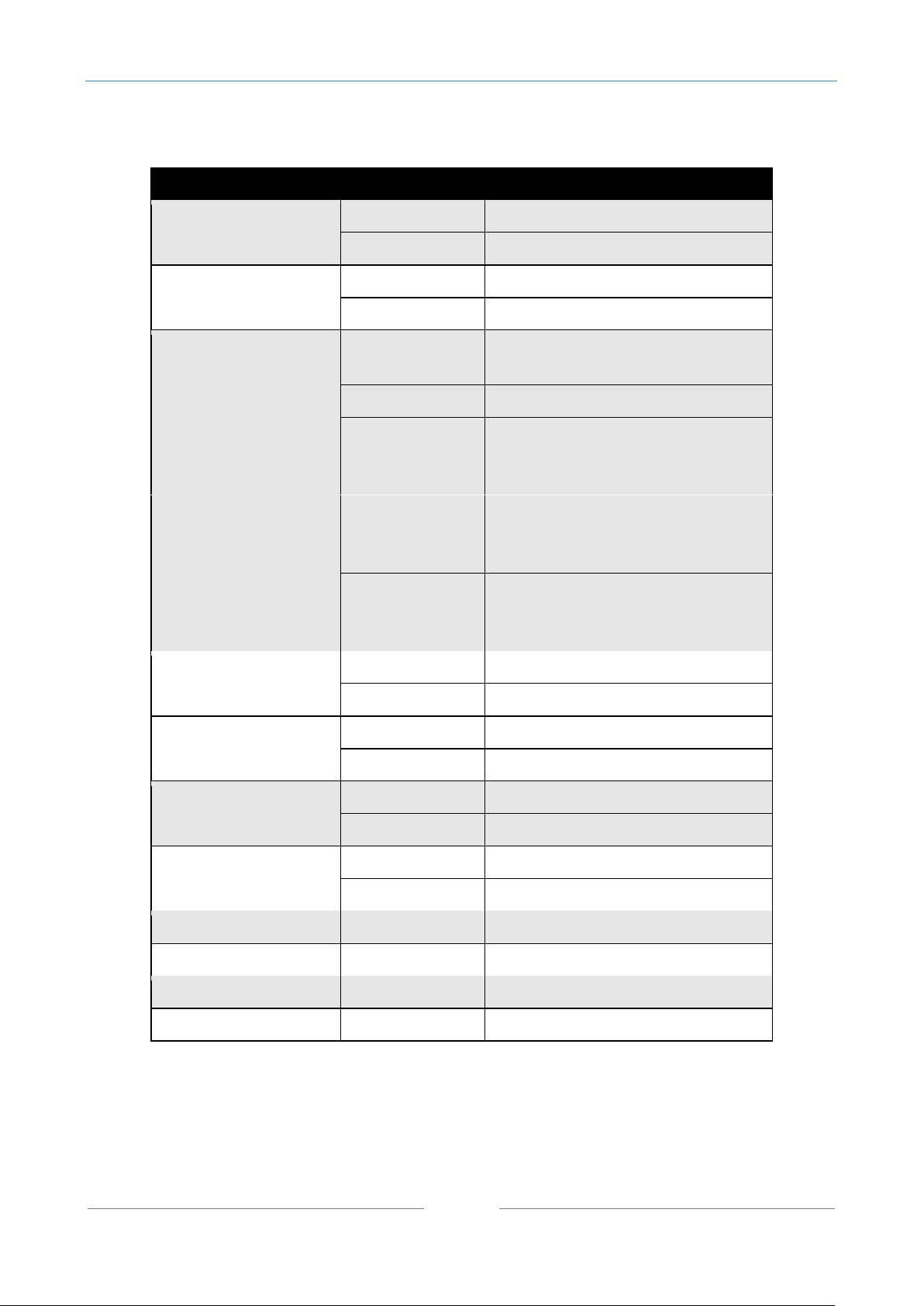
10.2. Program Execution in the Graph Panel
The execution of the program is from left to right, if there is more than one graph all the lines are executed
simultaneously:
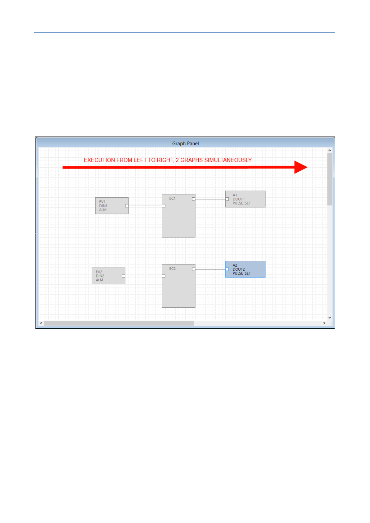
10.3. How SEAL works
SEAL works with the “from event to action” approach, this image will explain the concept:
USER MANUAL – Z-GPRS2-SEAL / Z-LOGGER-SEAL
33
One or more events must be connected to an event control, this block performs the logic and select the
right action output.
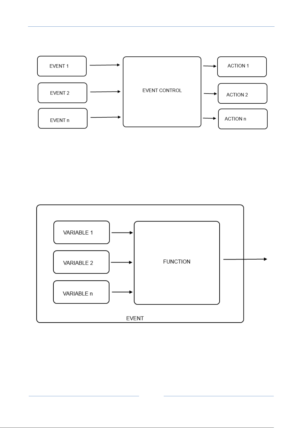
An Event can be created by a single block (for example a Digital input event) or by more than one blocks
using variables and functions:
In SEAL a single event block is for example a Digital input alarm event:
USER MANUAL – Z-GPRS2-SEAL / Z-LOGGER-SEAL
34
Where the event output becomes True if for example the digital input is high.
A multi-blocks event can be (Analog IN1-Analog IN2) > 0:
In the example the event output becomes True if Analog Input 1 > Analog Input 2.
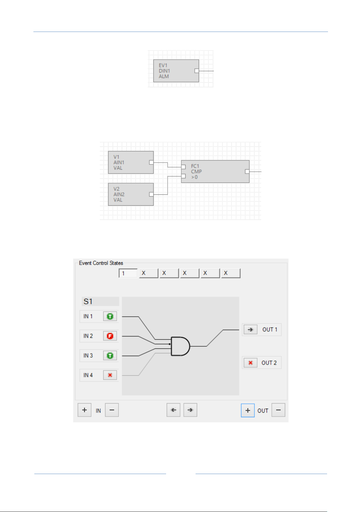
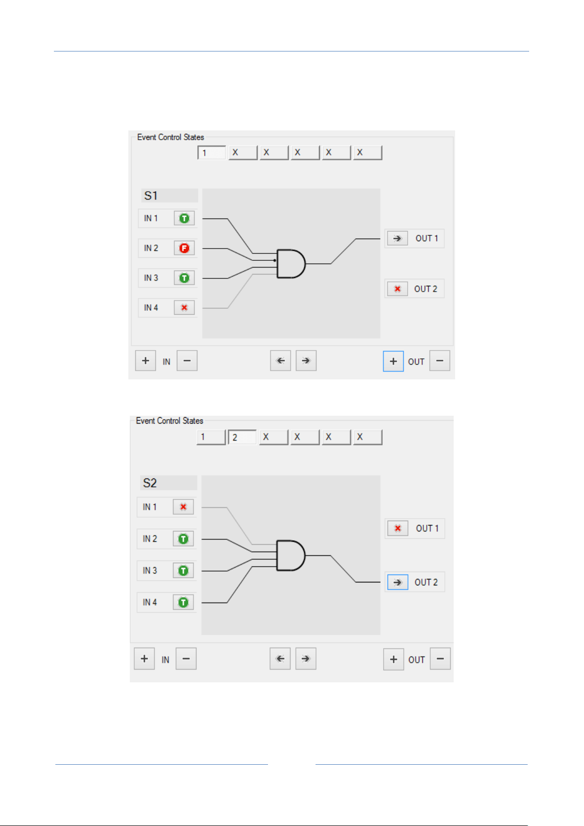
The Event Control select the right output action if the input conditions are verified:
In this example if IN1=True, IN2=False and IN3=True, the Action connected to the OUT1 is executed.
Every Event Control block can evaluate a maximum of 6 inputs and 6 outputs.
USER MANUAL – Z-GPRS2-SEAL / Z-LOGGER-SEAL
35
Every Event Control block can route up to 6 different input-output routes:
Route 1:
Route 2:
Etc…
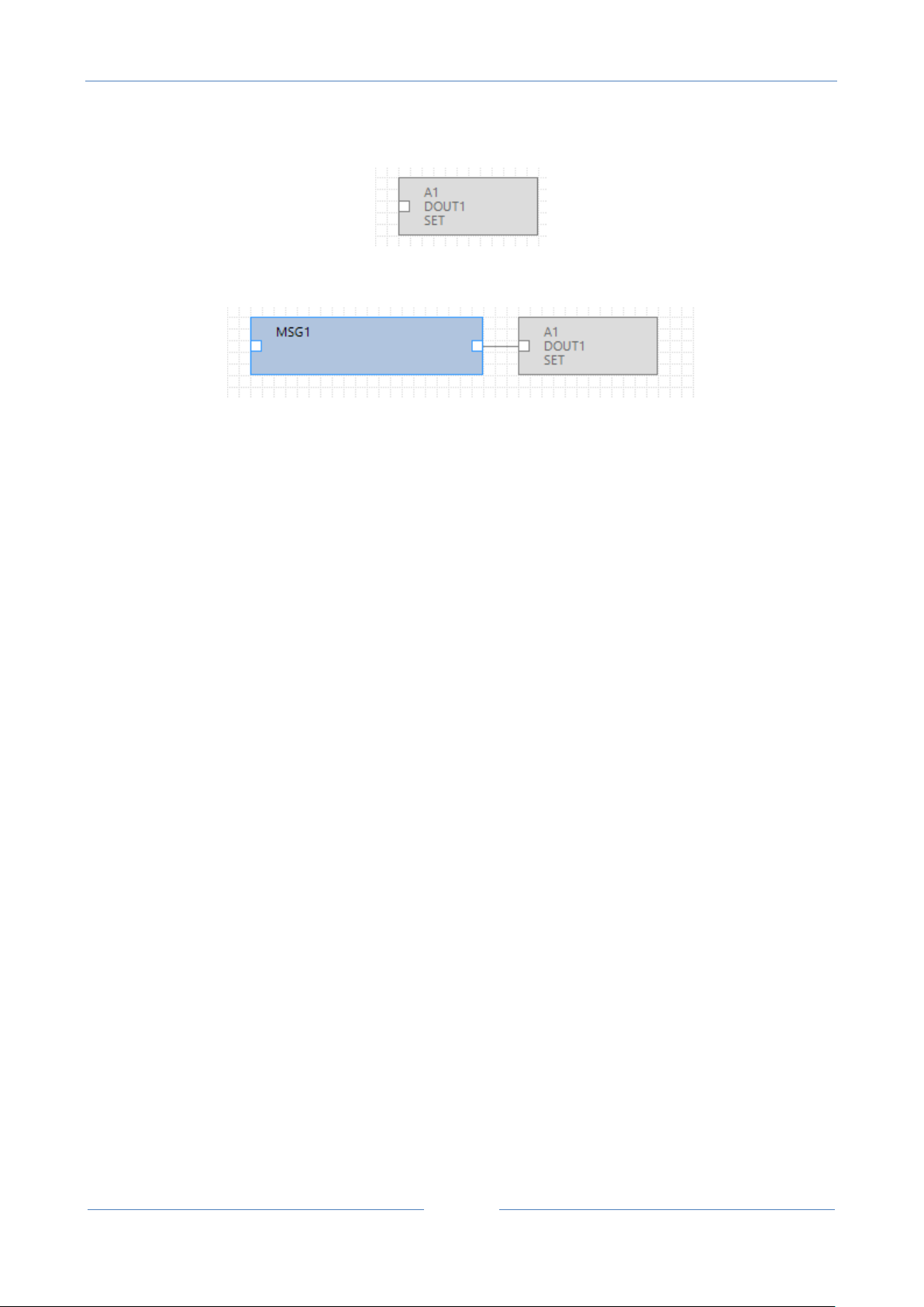
Actions can be performed for example on the digital ouputs or on the Modbus, for example:
USER MANUAL – Z-GPRS2-SEAL / Z-LOGGER-SEAL
36
A “Set Output 1” action block:
Or can be a multiple block action, for example send a message and set dout1:
11. The SEAL menu bar
The SEAL menu bar is composed by the following items:
File
Edit
Project
RTU
Build
Window
Help
11.1. Menu File
New will create a new SEAL project.
Load will open an existing project from a “.seal” file.
Save will save the current project to a “.seal” file.
Save as will create a copy of the current to project to a new file.
Quit will quit from SEAL.
11.2. Menu Edit
USER MANUAL – Z-GPRS2-SEAL / Z-LOGGER-SEAL
37
Undo This undoes the most recent action in the Graph Panel
Redo This redoes the most recent action that you've undone in the Graph Panel, if any.
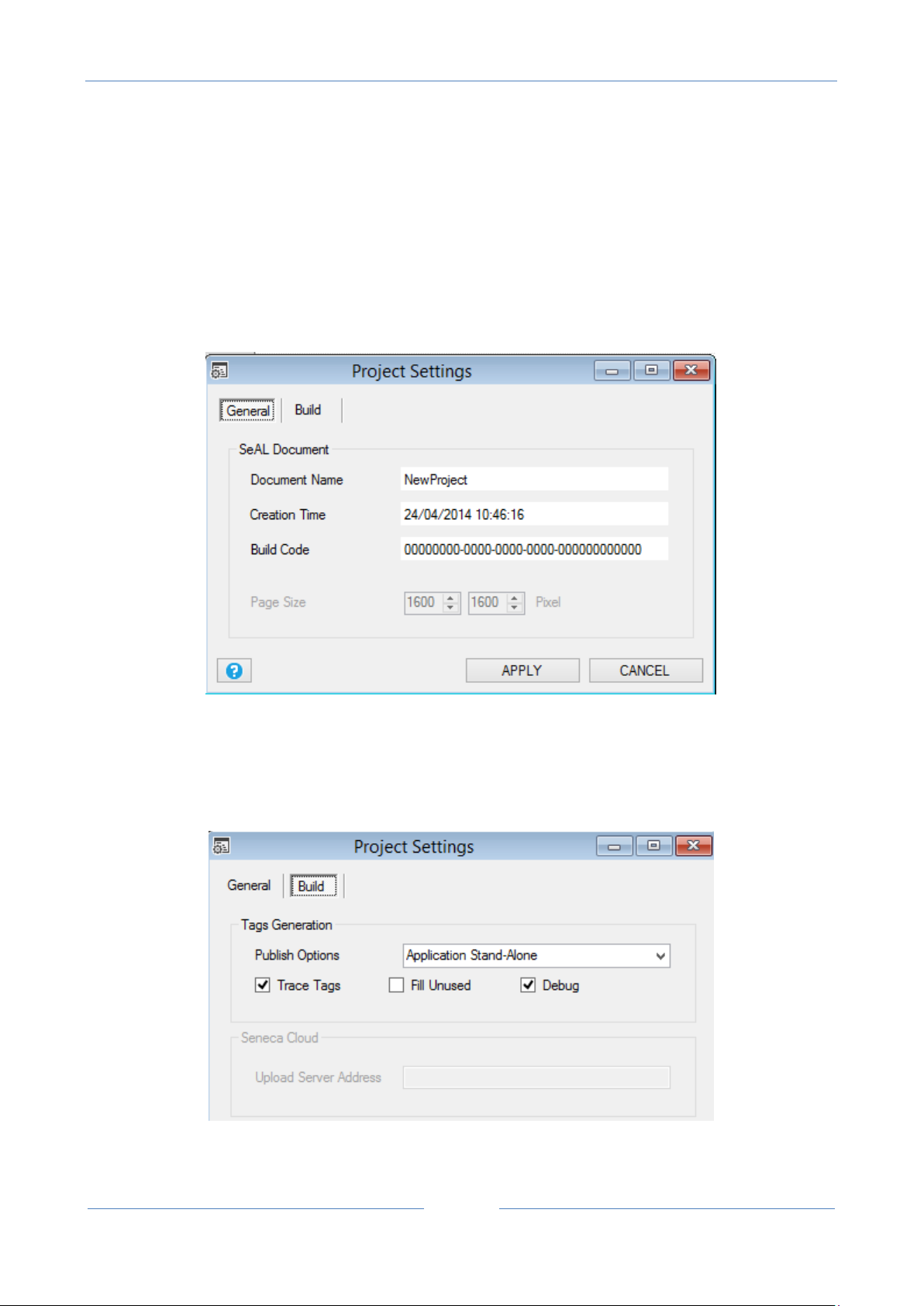
11.3. Menu Project Project Settings
General
Reports the information related the actual settings.
Build
Publish Options: Select how SEAL must compile the project, consider that:

USER MANUAL – Z-GPRS2-SEAL / Z-LOGGER-SEAL
38
Default User Groups
Capability 1)
Capability 2)
Capability 3)
Capability 4)
Manager
Yes
No
No
No
Logs
No
Yes
No
No
1) The Configuration contains only the connection parameters
2) The Program contains all the SEAL program but not the connection parameters (so if you send to a
remote RTU there is no possibility to put the RTU offline by a configuration error)
3) The Application contains the configuration and the program.
select from:
Application Stand-Alone: Create a compiled project with connection configuration and program (create all).
Program Stand-Alone: Create a compiled project with only program.
Cloud Application (Configuration+Program): For future use.
Cloud Program: For future use.
Cloud Application: For future use.
Tarce Tags: If checked show in the Log window the compiled values
Fill unused: If checked compile all the registers (also not used), if not checked compile only the used
registers (so the “sent to RTU” phase is faster).
Debug: If checked enable the advanced debug tools.
11.4. Groups, Profiles and Users
The RTU Z-Gprs2 and Z-Logger have an advanced user access management.
The main idea is that an user can have or not the following capabilities:
1) Send SMS commands to the RTU.
2) Receive SMS/E-mail with a notification log.
3) Receive SMS/E-mail of a specific notification alert.
4) Receive SMS/E-mail of all the notification alerts.
These capabilities are represented by a User Group or by one Special User Profile (administrator).
There are 3 default user groups with the following capabilities:

USER MANUAL – Z-GPRS2-SEAL / Z-LOGGER-SEAL
39
Alerts
No
No
Yes
No
Default User Profiles
Capability 1)
Capability 2)
Capability 3)
Capability 4)
Administrator
Yes
Yes
Yes
Yes
Manager
Yes
No
No
No
USER BETTY
Must receive the digital input 1
SMS notification alerts
Must receive the E-mail log
notifications USER BILL
Must send SMS commands
Must receive the digital input 2
SMS notification alerts
USER PAUL
Must receive the E-mail log
notifications USER ANTONY
Must send SMS commands
Must receive all the SMS
notification alerts
Must receive the E-mail log
notifications
There is also one default special user profiles (not a User Group) that has all the capabilities:
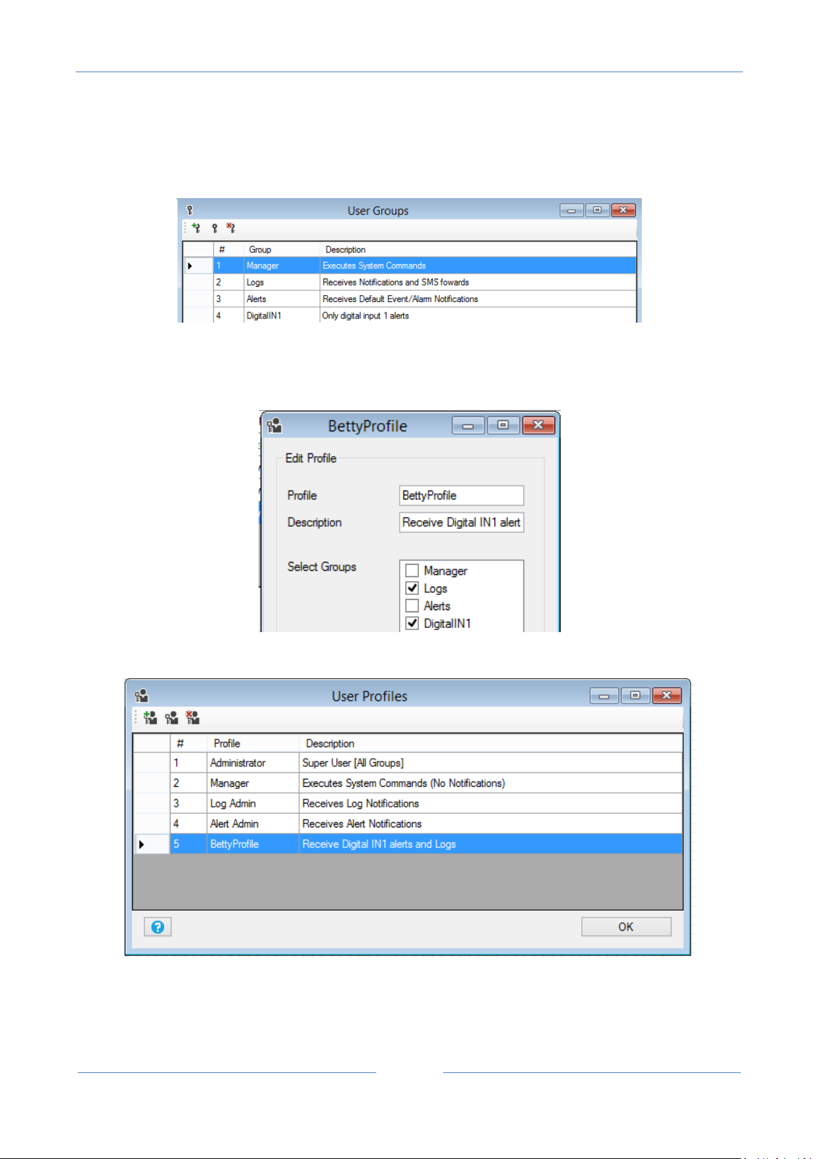
For example we need to obtain this policy:
USER MANUAL – Z-GPRS2-SEAL / Z-LOGGER-SEAL
40
Betty must receive only the digital input 1 SMS notification alerts so we need to create a custom group
(DigitalIN1):
Now we need to create a new user profile (BettyProfile) that include the custom group DigitalIN1 and the
Logs group:
And then we add the Betty user with the new BettyProfile:

USER MANUAL – Z-GPRS2-SEAL / Z-LOGGER-SEAL
41
Bill must send SMS commands so must include the group manager, must also receive digital input 2 alerts
so we need to create a custom group (DigitalIN2):
So we must create the custom User Profile (BillProfile):

USER MANUAL – Z-GPRS2-SEAL / Z-LOGGER-SEAL
42
And then we add the Bill user with the new BillProfile:
Paul must receive only log notifications so he must directly use the default log admin user profile:

USER MANUAL – Z-GPRS2-SEAL / Z-LOGGER-SEAL
43
Antony must use the Administrator special user profile because he must receive all the SMS notification
alerts. So we modify the Administrator Profile:
The relations are summarized here:

USER MANUAL – Z-GPRS2-SEAL / Z-LOGGER-SEAL
44
11.5. Menu Project: Users
Z-GPRS2/Z-Logger SEAL can manage a Phone numbers and E-mails address book.
The maximum numbers of Users is 8 (note that an extended address book is also available for the “ring
command” action, this extended address book support up to 1000 different users).
For create a new user use the icon, for delete a user use the icon.
For modify a user configuration use the icon.
CAUTION!
Commands SMS or call from user that are not present into the users phonebook have no effect. It’s also
possible to configure the Z-GPRS2 SEAL to resend this SMS to the Administrator profile.

USER MANUAL – Z-GPRS2-SEAL / Z-LOGGER-SEAL
45
Default User Groups
Can send SMS
commands
Can receive log
notifications
Can receive
specific alert
notifications
Manager
Yes
No
No
Logs
No
Yes
No
11.6. Menu Project: User – Add User
The icons and will open the following window:
User is the User description name
Description is a text description for the user
Profile Select the profile to assign to the user, you can select the profiles Admin, Manager, Log Admin, Alert
Admin or a custom profile.
Phone number if the RTU have a modem GSM/GPRS this is the user telephone number (used for calls or
SMS)
E-MAIL address this is the user E-MAIL address (used for alert notifications or/and log notifications)
11.7. Menu Project: User Groups
There are 3 default user group with the following capabilities:

USER MANUAL – Z-GPRS2-SEAL / Z-LOGGER-SEAL
46
Alerts
No
No
Yes
Also custom user groups can be created (but the capabilities that they have are only the specific alert
notifications.
A user profile must include at least one group, the user capabilities are determinate by the user groups that
are present in his user profile.
11.8. Menu RTU: Connection
Connection port is the serial port connected to the PC, select the right Z-GPRS2/Z-logger virtual com port,
note that you must first connect the Z-GPRS2/Z-Logger and then after.
Press the icon to refresh the serial ports after a connection.
Automatic COM Search performs an automatic search for Z-GPRS2/Z-Logger on all the attached serial
COM.
Rtu info Displays the information about the RTU name, firmware version, MAC address, Modem IMEI
address and Application identification code.
Connect Starts for searching Z-GPRS2/Z-Logger.
Close Close the window.

USER MANUAL – Z-GPRS2-SEAL / Z-LOGGER-SEAL
47
11.9. Menu RTU Test Monitor
To start the real time data viewer you must be connect with the Z-GPRS2/Z-Logger and press the play
button.
Press the stop button to stop acquiring real time data.
Now you can view real time data.
General
RTU Clock will show the actual RTU time/data.
RTU Clock Synchronization is used for synchronize the clock with the PC clock or to a custom time/data.
Press the “SYNC” button to start the synchronization process.
Modem GSM will show the actual GSM/GPRS signal quality filed. The field is expressed in dBm where -
115 dBm it’s the minimum, -52 dBm it’s the maximum.
This table can be used:

USER MANUAL – Z-GPRS2-SEAL / Z-LOGGER-SEAL
48
GSM Signal
GSM signal [dBm]
0 (MINIMUM)
-115
1
-106 2 -97 3 -88 4 -79 5 -70 6 -61
7 (MAXIMUM)
-52
Where 0 it’s the minimum, and 7 it’s the maximum.
For correct ftp or email log operations the minimum required field level is 2/7 (please remember
that the signal often fluctuates).
For SMS operations only the minimum required field level is 2/7.
Refer to the following table for signal values:
SIGNAL LEVEL 0 = NO SIGNAL (INSUFFICIENT)
SIGNAL LEVEL 1 = INSUFFICIENT SIGNAL (NOT RELIABLE FOR SMS AND GPRS)
SIGNAL LEVEL 2 = SUFFICIENT SIGNAL (MINIMUM SIGNAL FOR SMS AND GPRS)
SIGNAL LEVEL 3 = RELIABLE SIGNAL (RELIABLE FOR SMS AND GPRS)
SIGNAL LEVEL 4 = GOOD SIGNAL
SIGNAL LEVEL 5 = VERY GOOD SIGNAL
SIGNAL LEVEL 6 = OPTIMAL SIGNAL
SIGNAL LEVEL 7 = EXCELLENT SIGNAL
To increase the GSM signal level, Seneca provides various GSM antenna models for Z-GPRS2 to
reach the minimum signal level in most situations.
Visit (www.seneca.it) or refer to the general catalogue or contact Seneca srl for further
information.
Battery Charge will show the actual battery charge, if the value it’s below 2/7 you must wait at
least 24h for a full recharge before use Z-GPRS2/Z-Logger power backup.
USER MANUAL – Z-GPRS2-SEAL / Z-LOGGER-SEAL
49
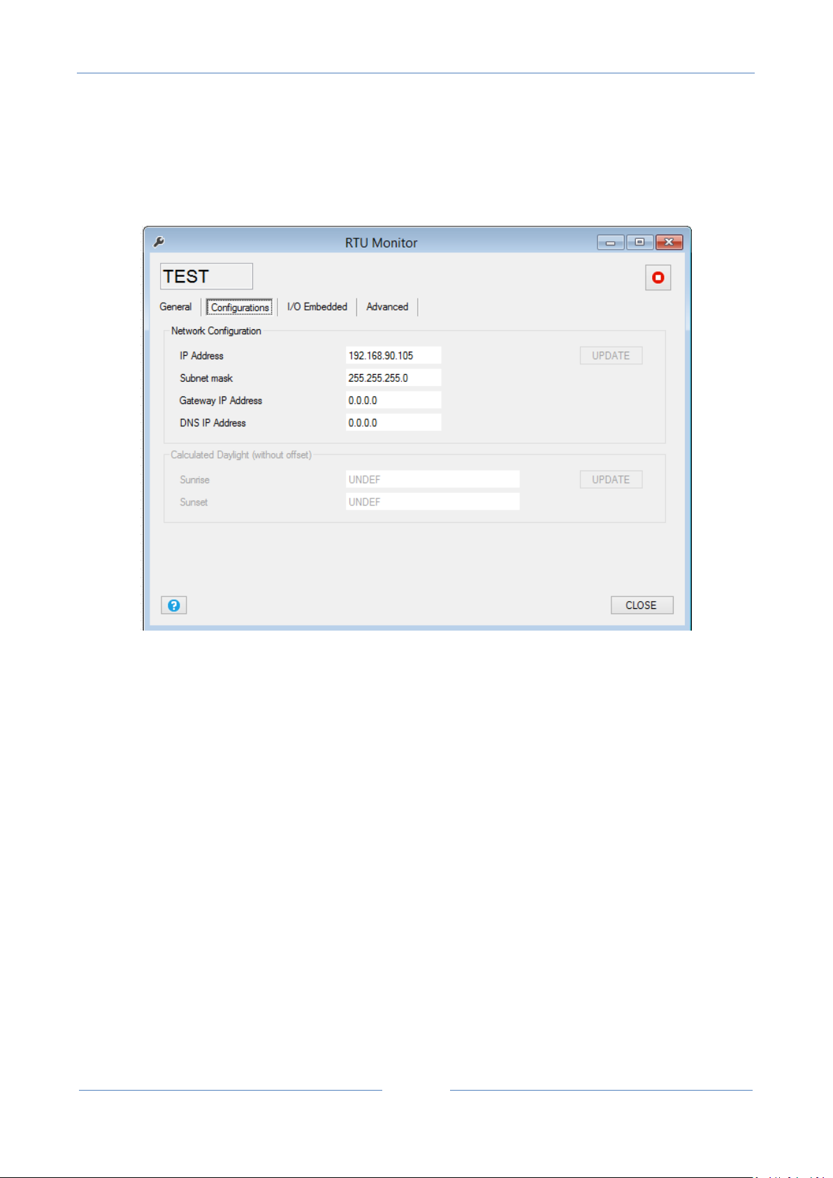
Configurations
In this section you can see the IP Address configuration and the Calculated Sunrise and Sunset time (if they
are configured).
USER MANUAL – Z-GPRS2-SEAL / Z-LOGGER-SEAL
50
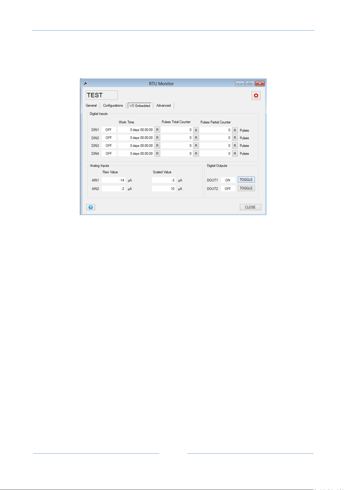
I/O embedded
Digital Inputs show the Digital input state ON/OFF, the work time input. Also are presents the
Total and Partial counters (raw values not scaled).
Analog Inputs show the Raw and the scaled Analog input 1 and 2 values.
Digital Outputs show the digital out 1 and 2 actual value, you can force a digital ouput value using
the “Toggle” button.
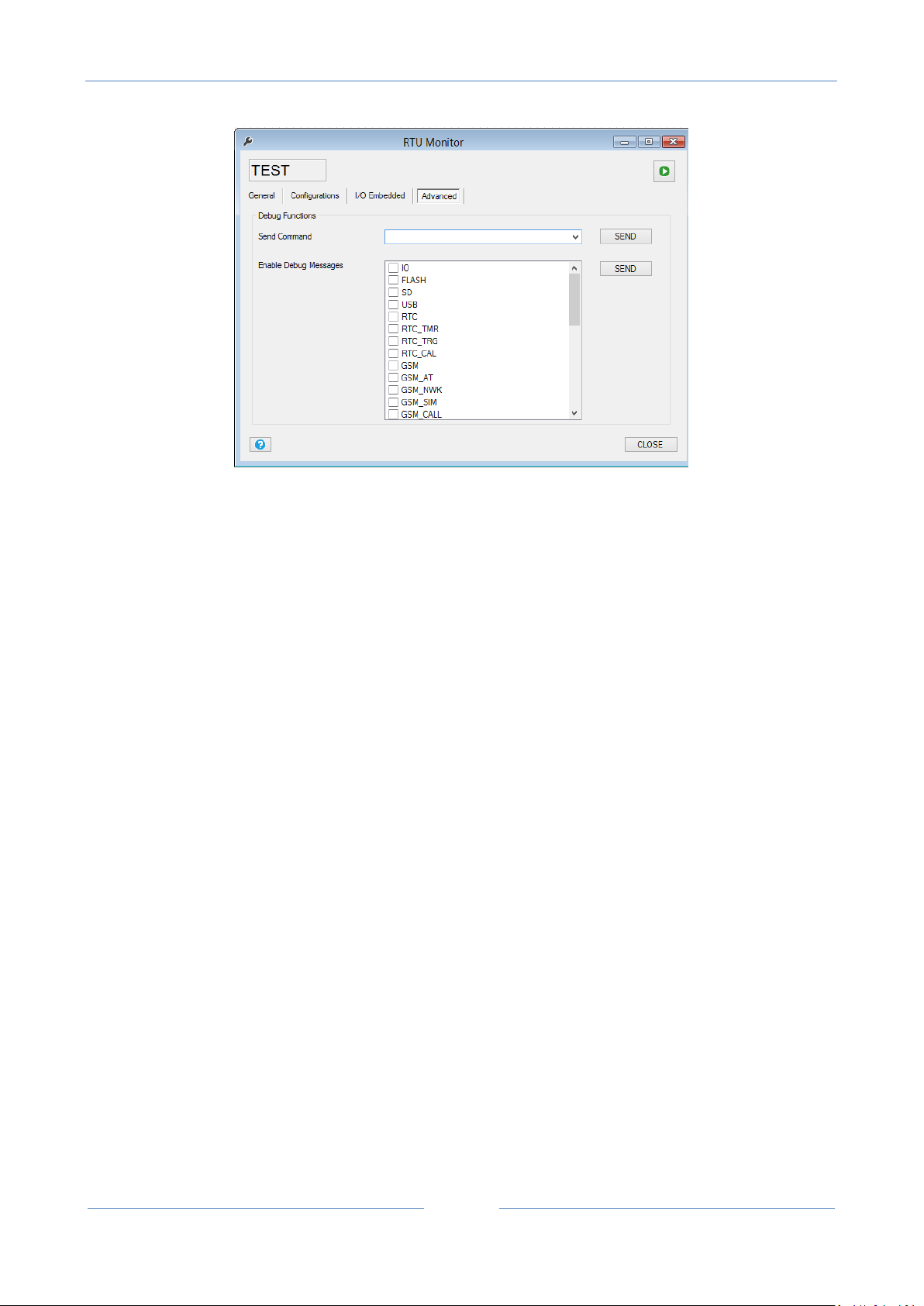
Advanced
USER MANUAL – Z-GPRS2-SEAL / Z-LOGGER-SEAL
51
The advanced section can be used for send commands to the RTU, the commands are:
Reset RTU : perform a RTU reset.
Unmount SD: when the microSD card is unmounted can be extracted and insert to an external reader.
Stop log: the logger will be stopped.
Start log: the logger will start.
Dump Logs to SD: will copy all data in the internal flash memory to the microSD.
Reset Logs: will erase all the internal flash memory logs.
Send TEST Email Message: will send a test e-mail to the administrators.
Send TEST FTP File: will send a test file to the configured FTP and directory.
Restart Modem GSM: will reset the GSM modem.
Stop Master Modbus: will stop to acquire data log from Modbus RTU / Modbus TCP-IP
Start Master Modbus: will restart to acquire data log from Modbus RTU / Modbus TCP-IP
Firmware Download from FTP Server: will download and then update the actual firmware from the
configured FTP server and directory, if the firmware revision is the same in use, the firmware update will
not be executed. Note that a firmware update can delate the actual configuration, at startup the firmware
will search for a new setup file. The firmware file name must be “fwupdt.bin”, the setup file must be
“fwupdt.tag”.

USER MANUAL – Z-GPRS2-SEAL / Z-LOGGER-SEAL
52
Setup Download from FTP Server: will force to download and use the SEAL configuration and program that
are to be used with a firmware update. The Setup configuration for security reason don’t contain the
connection parameters (use the Application file for a full configuration). The setup file must be “setup.tag”.
Application Download from FTP Server: will force to download and use a full SEAL configuration and
program. the setup file must be “setup.tag”.
Phonebook Download from FTP Server: will force to update the extended ring action address book. Use the
“convert phonebook csv” item from the RTU menu for convert an address book csv file. The file name must
be “data.bin”.
Firmware Update from SD: will force to update the firmware from the microSD card root. The file name
must be “fw.bin”
Setup Update from SD: will force to use the SEAL configuration and program to be used with a firmware
update that is in the microSD root. The Setup configuration for security reason don’t contain the
connection parameters (use the Application file for a full configuration). The setup file must be “setup.tag”.
Application Update from SD: will force to use the SEAL configuration and program to be used with a
firmware update that is in the microSD root. The Setup configuration for security reason don’t contain the
connection parameters (use the Application file for a full configuration). The setup file must be “setup.tag”.
Phonebook Update from SD: will force to update the extended ring action address book that is in the
microSD root. Use the “convert phonebook csv” item from the RTU menu for convert an address book csv
file. The file name must be “data.bin”.
Test RING: will force a ring call to the first administrator.
Test Fast Command: will execute the selected fast command.
Enable Debug Messages: is used for activate the Debug serial port, selecting what the port must outputs.
11.10. Menu RTU: FW Update
This item is used for update the firmware by the USB connection. Make sure that the file that you are using
is a correct Z-GPRS2/Z-Logger .bin firmware.
Caution!
If you update the RTU with an error firmware the Z-GPRS2/Z-Logger will stop to work and they will be
damaged! Seneca warranty don’t cover the effects of an update by an error firmware file.

USER MANUAL – Z-GPRS2-SEAL / Z-LOGGER-SEAL
53
11.11. Menu RTU: Open project from RTU
With this menu item the project will be open from the connected Z-GPRS2/Z-Logger, note that if the
project isn’t present in the actual PC you will not be able to open the project.
11.12. Menu RTU: Convert Phonebook CSV
This item will convert a text file .csv file to a .bin file ready for use for the extended phonebook.
The extended Phonebook consist in a list of phone numbers (max 1000 numbers) that will be able to
activate the ring command configured. The .csv list file must be like this (note the country code in every
number), an enter between the numbers must be entered:
For more info refer to chapter 23.
11.13. Menu Build: Generate
This item will compile the actual project, if no errors are detected a build ok message will be displayed.
If errors are detected an error message will be displayed and in the Ouput Messages a description of the
errors will be underlined:

USER MANUAL – Z-GPRS2-SEAL / Z-LOGGER-SEAL
54
If the build process fail it’s not possible to send the project to the RTU.
11.14. Menu Build: Generate and send to RTU
This item will build and then send the project to the RTU.
if no errors are detected a build ok message will be displayed.
If errors are detected an error message will be displayed and in the Ouput Messages a description of the
errors will be underlined:

USER MANUAL – Z-GPRS2-SEAL / Z-LOGGER-SEAL
55
If the build process fail it’s not possible to send the project to the RTU.
11.15. Menu Window: Build Output
This item will show the Output Message window:
If in the build process errors are detected, the errors description will be underlined in the Output Messages
window:
11.16. Menu Window: Edit Form
This item will bring on top the edit window that is open.
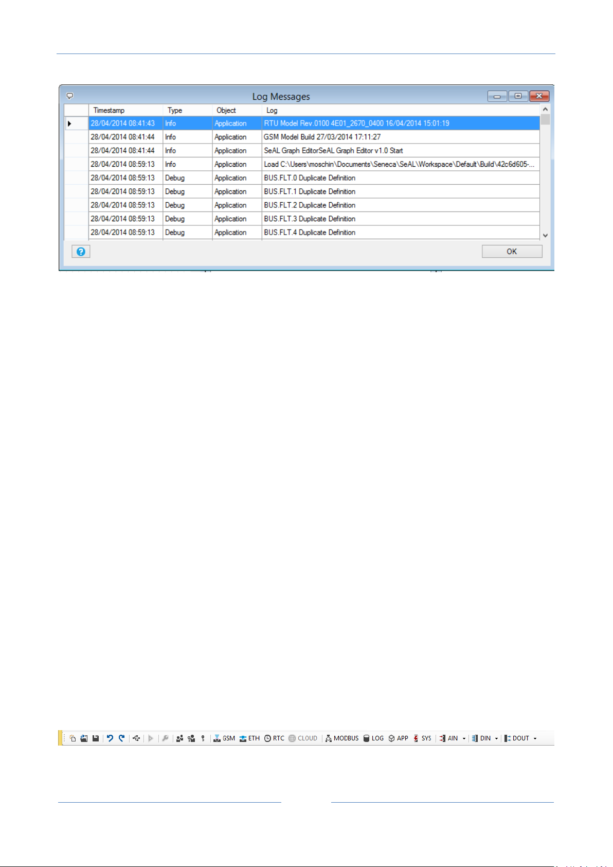
11.17. Menu Window: Logs
All the software activity is logged in a file, you can view the data in the Logs window:
USER MANUAL – Z-GPRS2-SEAL / Z-LOGGER-SEAL
56
11.18. Menu Window: Default Layout
The default Layout configure the SEAL windows in the default layout.
11.19. Menu Window: Tile Horizontal
The Tile Horizontal configure the SEAL windows in the Tile Horizontal layout.
11.20. Menu Window: Tile Vertical
The Tile Vertical configure the SEAL windows in the Tile Vertical layout.
11.21. Menu help
This item will open this document file.
12. The SEAL Icon Menu
The SEAL icon menu is a collection of the most useful setup window:
USER MANUAL – Z-GPRS2-SEAL / Z-LOGGER-SEAL
57
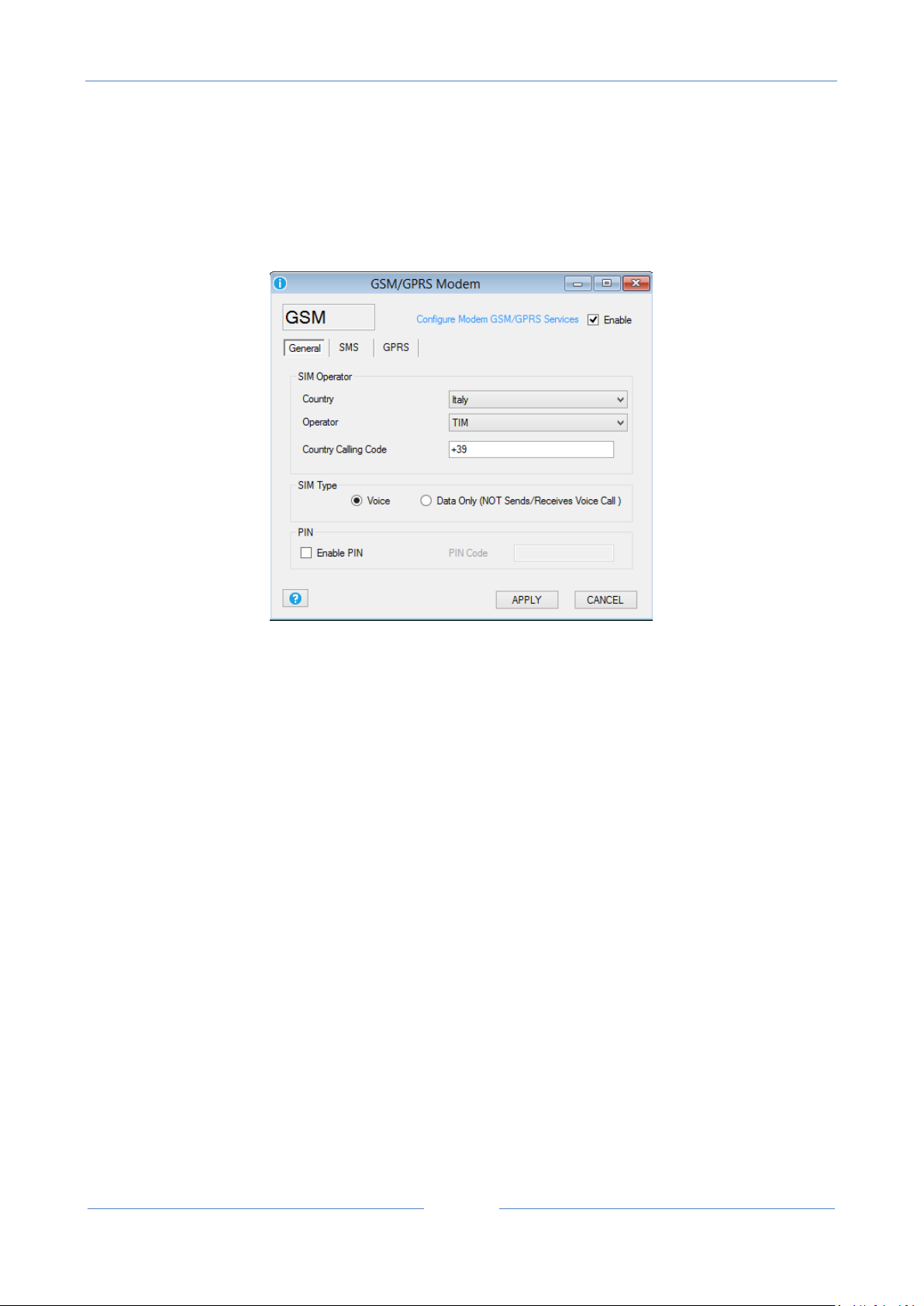
12.1. GSM/GPRS Modem
General
This window will configure the GSM/GPRS modem (only for model Z-GPRS2).
Country Select the SIM country from the database.
Operator Select the SIM mobile operator from the database or use the Custom operator.
Country Calling Code Select the right country code, note that you must add the “+” character too.
SIM Type Select if you are using a only data SIM or a voice/data sim, a only data SIM cannot make ring.
PIN Select the Pin for protect the SIM card access, use a mobile phone for enable/disable the SIM PIN code.
SMS

USER MANUAL – Z-GPRS2-SEAL / Z-LOGGER-SEAL
58
This window will configure the modem SMS functions:
Forward Unrecognized SMS to Administrator: if checked every SMS with unknown number will be
forwarded to the first of the administrators. Use this function for forward mobile operator
messages too.
Enable SMS Service Center Number: if checked force the SMS service center instead of the service
center registered into the SIM.
Credit request: this function can be used for rechargeable SIM remaining credit. Contact the
mobile operator for info about obtaining the remaining credit, options are: call a number (ring to a
specific number) or send an SMS with a specified text. Note that this functions works only with
rechargeable SIM.
GSM/GPRS Modem: GPRS

USER MANUAL – Z-GPRS2-SEAL / Z-LOGGER-SEAL
59
Enable GPRS Service: if checked activate the GPRS internet connection.
APN: Select the Mobile operator Access Point Name server for internet connection, contact your mobile
operator for more information.
APN Authentication Required: Select if the APN needs or not a user name and password for access
Enable RTC Sync: Enable the Data/hour synchronization by the GPRS connection.
12.2. Ethernet Services
General

USER MANUAL – Z-GPRS2-SEAL / Z-LOGGER-SEAL
60
Enable DHCP: If checked enable the Dynamic Host Configuration Protocol, the IP address, and the Subnet
mask are obtained automatically from the DHCP server (often the router/gateway).
IP Address: Enter the static IP address.
Subnet mask: Enter the Subnet Mask.
Gateway IP Address: Enter the Gateway/Router IP address for accessing to internet.
DNS IP Address: Enter the Domain Name Server, use 0.0.0.0 for takes the DNS address automatically from
the Gateway/Router.
Web/FTP Server

USER MANUAL – Z-GPRS2-SEAL / Z-LOGGER-SEAL
61
FTP Server: If checked enable the internal FTP server, the FTP server file system is the microSD card so you
can acquire the log files directly from the FTP server. For use an FTP client remember to force the “only one
connection” option, for example in filezilla ftp client:
Also the FTP port can be configured (default 21).

USER MANUAL – Z-GPRS2-SEAL / Z-LOGGER-SEAL
62
Web Server: If checked enable the Web server, with the Web server is possible to view the real time values
of the embedded IO and the Modbus RTU/TCP-IP IO:

USER MANUAL – Z-GPRS2-SEAL / Z-LOGGER-SEAL
63
HttpDocs in SDCARD: If checked load the webserver html custom pages from the SDcard. The html file
must be in /httpdocs and the start pages must be “index.html”.
Enable Authentication: If checked you must enter a password for accessing the Web server and the FTP
Server. Seneca recommend always to enable the authentication for Web and FTP server.
CAUTION!
The FTP Server, Web server and Modbus server can only be used through the ethernet connection (not
with the GPRS).
CAUTION!
You can only configure or the FTP Server or the Web server simultaneously.
Modbus Server

USER MANUAL – Z-GPRS2-SEAL / Z-LOGGER-SEAL
64
MODBUS ADDRESS
REGISTERS
40008
DIGITAL INPUTS
BIT 0 = INPUT 1 (Least significant bit)
BIT 1 = INPUT 2
Enable Modbus TCP-IP Server: if checked enable the Modbus TCP-IP server, so it’s possible to read the real
time values of variables directly from a SCADA or an external display, PC etc...
The registers address are all holding registers, the first register (register 0) is the 40001.
MSW is for “Most Significant Word”
MSB is for “Most Significant Bit”
LSW is for “Least Significant World”
LSB is for “Least Significant Bit”
0x is an Hexadecimal Value

USER MANUAL – Z-GPRS2-SEAL / Z-LOGGER-SEAL
65
BIT 2 = INPUT 3
BIT 3 = INPUT 4
40009
DIGITAL OUTPUT (Read Only)
BIT 0 = OUTPUT1 (Least significant
bit)
BIT 1 = OUTPUT2
49001 0x0020
49002 0x0010
49003 0x0200
WRITEABLE ONLY IN ONE MULTIPLE
WRITE:
COMMAND FOR OPEN OUT 1
49001 0x0020
49002 0x0020
49003 0x0200
WRITEABLE ONLY IN ONE MULTIPLE
WRITE:
COMMAND FOR CLOSE OUT 1
49001 0x0020
49002 0x1000
49003 0x0200
WRITEABLE ONLY IN ONE MULTIPLE
WRITE:
COMMAND FOR OPEN OUT 2
49001 0x0020
49002 0x2000
49003 0x0200
WRITEABLE ONLY IN ONE MULTIPLE
WRITE:
COMMAND FOR CLOSE OUT 2
40131
ANALOG INPUT 1 (signed 16 bits)
40145
ANALOG INPUT 2 (signed 16 bits)
LSW 49405
MSW 49406
PARTIAL COUNTER 1 (WITHOUT
SCALE) (unsigned 32bits)
LSW 49409
MSW 49410
PARTIAL COUNTER 2 (WITHOUT
SCALE) (unsigned 32bits)
LSW 49413
MSW 49414
PARTIAL COUNTER 3 (WITHOUT
SCALE) (unsigned 32bits)
LSW 49417
PARTIAL COUNTER 4 (WITHOUT
SCALE) (unsigned 32bits)

USER MANUAL – Z-GPRS2-SEAL / Z-LOGGER-SEAL
66
MSW 49418
LSW 49407
MSW 49408
COUNTER 1 (WITHOUT SCALE)
(unsigned 32bits)
LSW 49411
MSW 49412
COUNTER 2 (WITHOUT SCALE)
(unsigned 32bits)
LSW 49415
MSW 49416
COUNTER 3 (WITHOUT SCALE)
(unsigned 32bits)
LSW 49419
MSW 49420
COUNTER 4 (WITHOUT SCALE)
(unsigned 32bits)
40158
GSM LEVEL (dBm)
40128
V BATTERY (min 2200, max 2800)
40008
BIT 7 = 1 POWER SOURCE OK
BIT 7 = 0 POWER SOURCE DOWN
48003
START SHARED MEMORY FOR
MODBUS LOG
…
…
48202
STOP SHARED MEMORY FOR
MODBUS LOG
All Datalogger real-time values logged by Modbus TCP-IP and Modbus RTU can be accessed via
modbus.
The format is created as follows: Logged registers are placed in the format one after the other
without leaving empty registers.
If, for example, the following registers are being logged:
Register 1: 16 bit unsigned
Register 2: 32 bit unsigned
USER MANUAL – Z-GPRS2-SEAL / Z-LOGGER-SEAL
67
Modbus address
Register
48003
Register 1
48004
Register 2 MSW
48005
Register 2 LSW
48006
Register 3 MSW
48007
Register 3 LSW
48008
Register 4
Register 3: Floating point single precision
Register 4: 16 bit signed
The obtained format is the following:
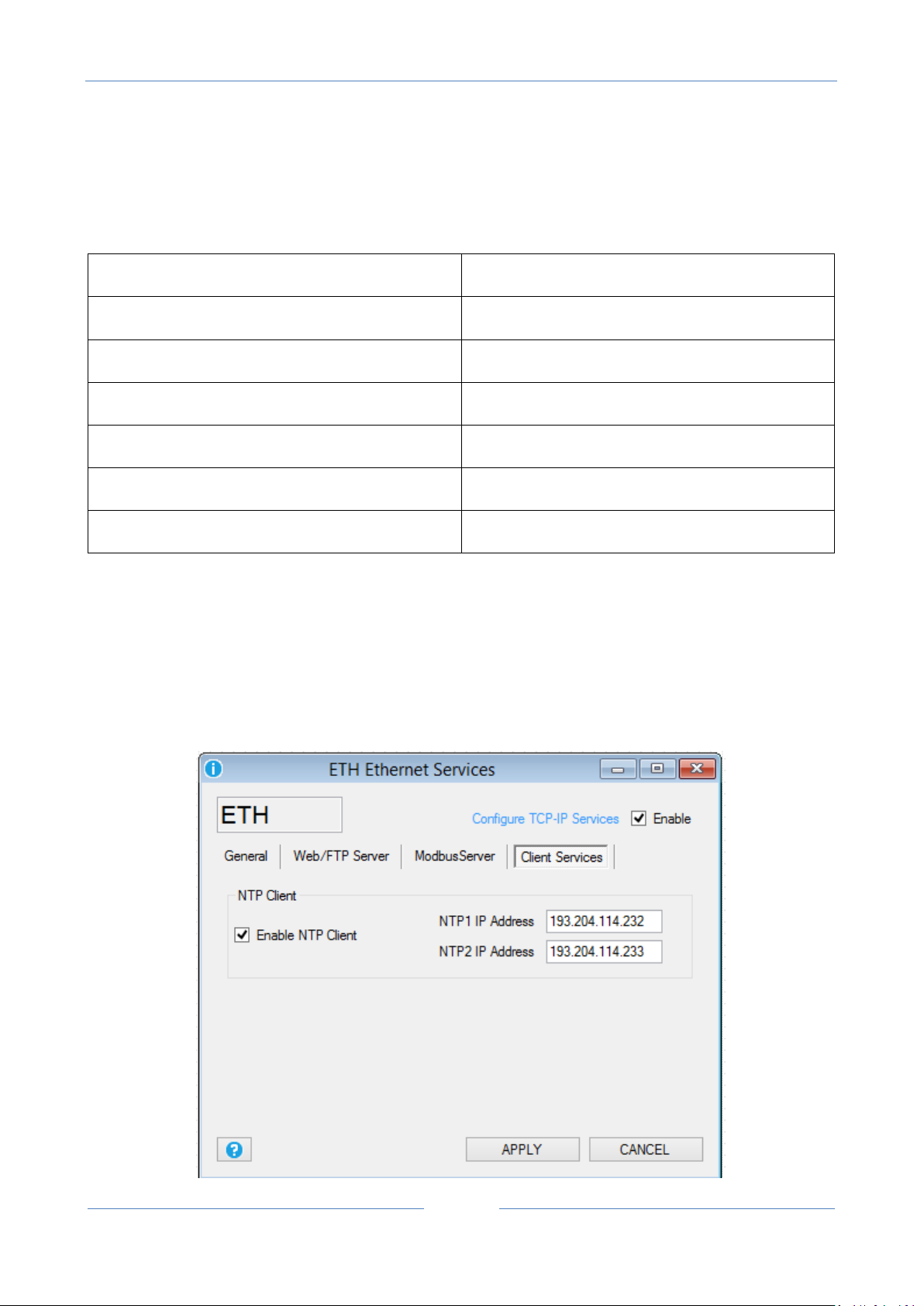
Client Services

USER MANUAL – Z-GPRS2-SEAL / Z-LOGGER-SEAL
68
NTP IP Address
DESCRIPTION
193.204.114.232
ntp1.ien.it (default)
193.204.114.233
ntp2.ien.it (default)
217.147.223.78
europe.pool.ntp.org
140.130.175.9
asia.pool.ntp.org
203.23.237.200
oceania.pool.ntp.org
66.250.45.2
north-america.pool.ntp.org
146.164.53.65
south-america.pool.ntp.org
196.25.1.9
africa.pool.ntp.org
Enable NTP Client: If checked enable the Network Time Protocol used for synchronize the RTU Date/Time.
The list of major NTP server is the follower:
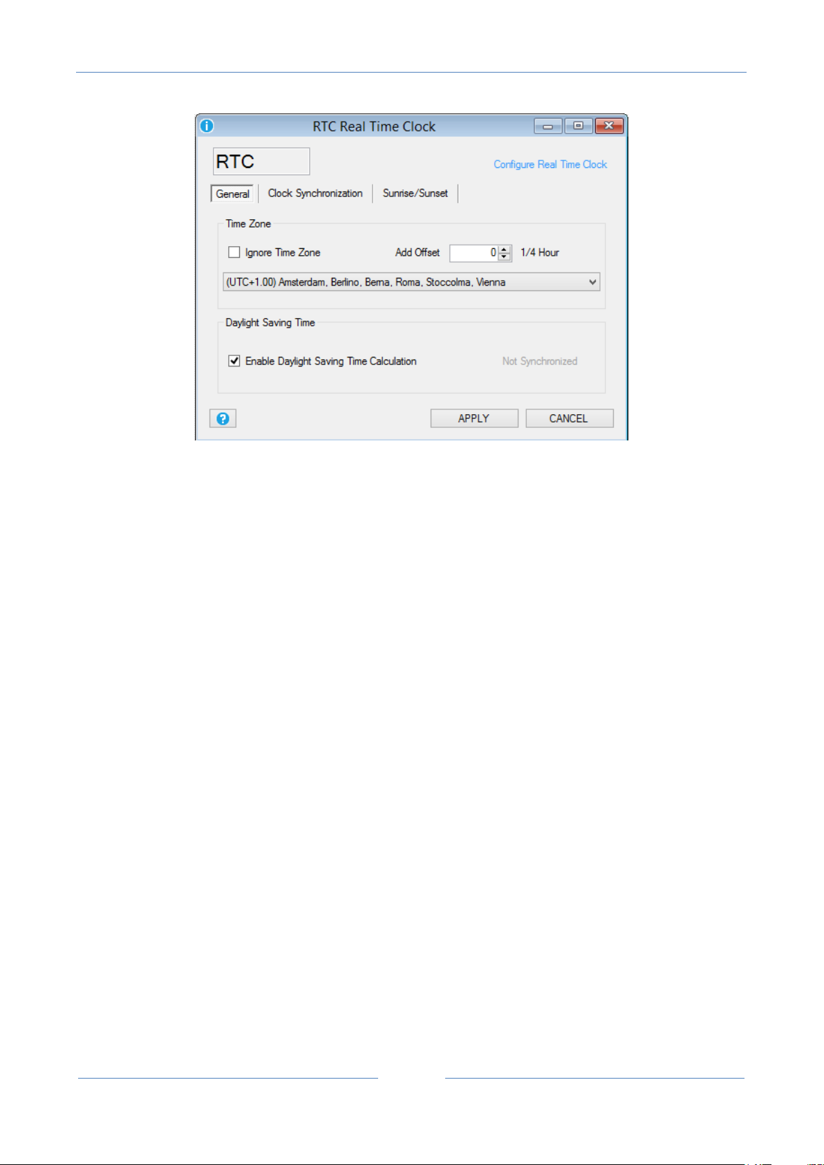
12.3. Real Time Clock
General
USER MANUAL – Z-GPRS2-SEAL / Z-LOGGER-SEAL
69
TIME ZONE: configure the RTU installation timezone, it’s possible to ignore timezone for set a custom
Date/Hour with SEAL software or set the right timezone. If you are using the Network Time Protocol (NTP)
from Ethernet or the GPRS for synchronize data/hour you must configure the right Timezone because the
server hour is UTC (Universal Time Coordinating). The UTC and GMT (Greenwich Medium Time) can be
defined as equal.
ENABLE DAYLIGHT SAVING TIME: enable the automatic calculation of the Daylight Saving Time (NTP
servers do not use the daylight saving time).
Clock synchronization
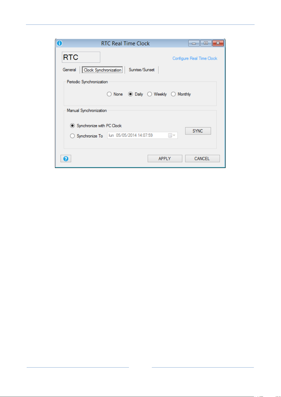
USER MANUAL – Z-GPRS2-SEAL / Z-LOGGER-SEAL
70
Periodic Synchronization: Select the synchronization time for the Ethernet Network Time Protocol or GPRS
automatic synchronization
Manual Synchronization: Select to synchronize manually using the PC Date/Hour or to a custom
Date/Hour, then press the SYNC button to actualize. Note that this operation is available only if the RTU is
connected to SEAL.
Sunrise and Sunset
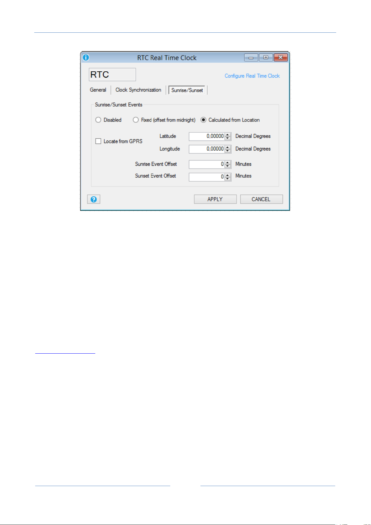
USER MANUAL – Z-GPRS2-SEAL / Z-LOGGER-SEAL
71
With a sophisticated algorithm, the RTU can calculate the Sunrise and Sunset events from the GPS
coordinates and from the Date/Hour. So it’s possible to use the events for turn on/off a lamp, stop the
datalogger etc..
It’ possible to fix an offset from midnight or calculate the events from the GPS coordinates.
If you select to calculate the sunrise/sunset from GPS you can select to insert the Latitude/Longitude
directly or using the GPRS network (Locate from GPRS).
The Locate from GPRS option use the coordinates from the GPRS antenna for obtaining the
longitude/latitude. If you don’t use the GPRS you must enter manually the Latitude/Longitude. For
obtaining the right coordinates in decimal degrees connect to:
http://maps.google.it
Select the place where you want to install the RTU then press the right mouse button and select “what’s
here?”
In the example:
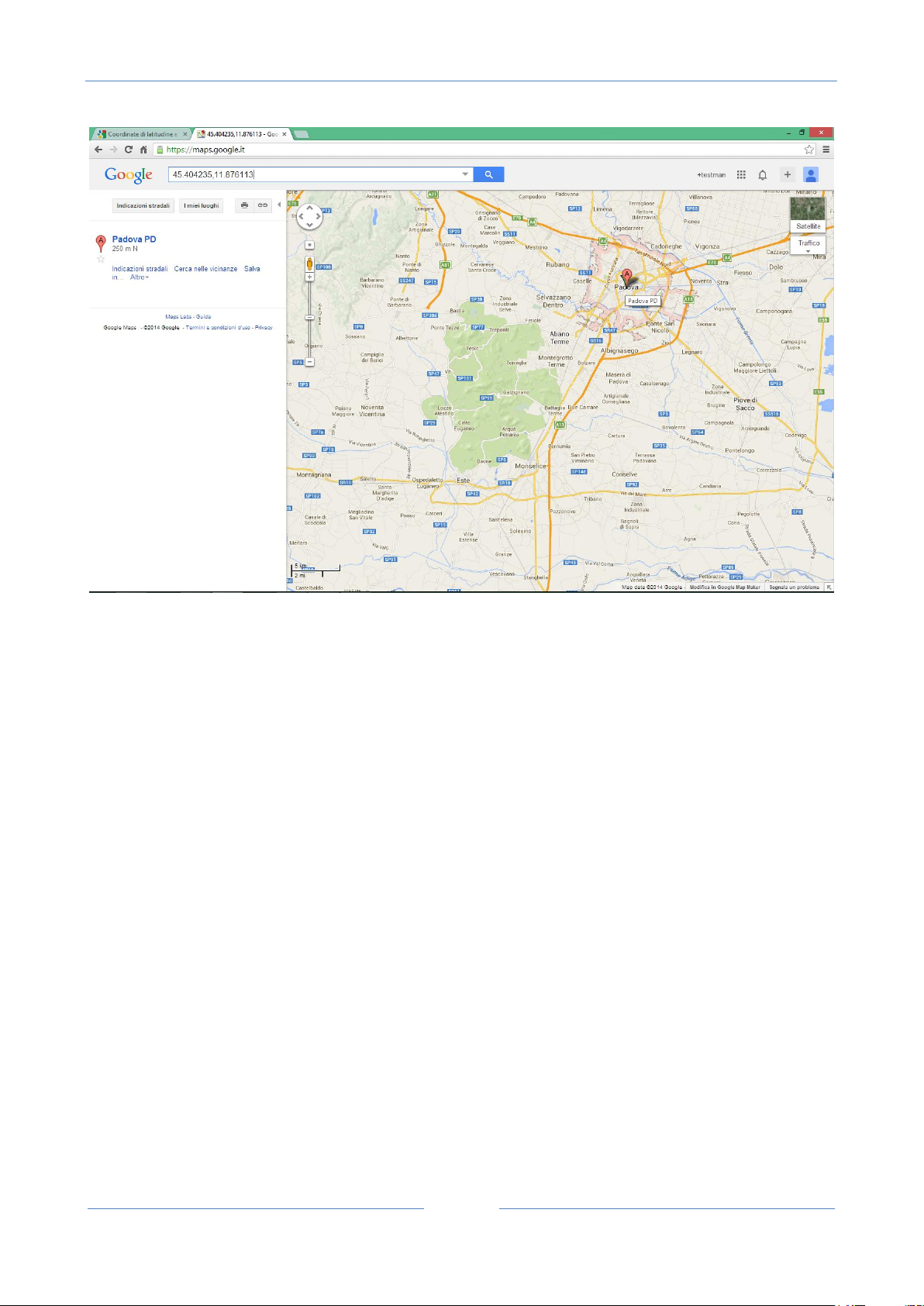
USER MANUAL – Z-GPRS2-SEAL / Z-LOGGER-SEAL
72
latitude 45.404235 decimal degree
longitude 11.876113 decimal degree
You can add an offset (in minutes) to the Sunrise/Sunset action too.
12.4. Cloud
General
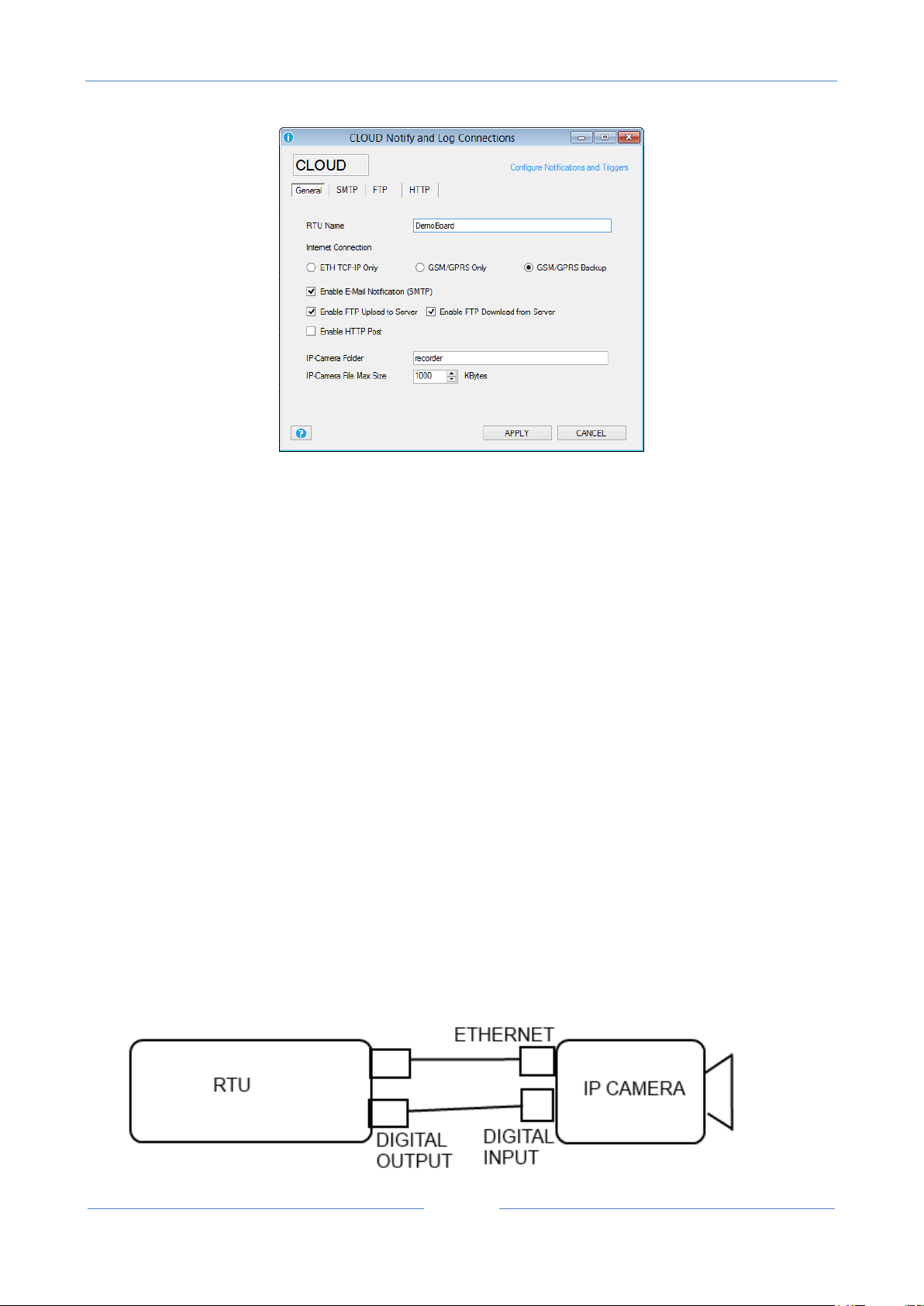
USER MANUAL – Z-GPRS2-SEAL / Z-LOGGER-SEAL
73
RTU Name: Enter the RTU Name, this name is also the prefix of the .csv log file name.
If your RTU Name is for example DemoBoard the csv log files will be like:
log_DemoBoard_20140404101513.csv
Internet Connection: Enter the connection port used for internet. You can use only the Ethernet, only the
GPRS or the Ethernet with backup on GPRS.
Enable E-MAIL Notification: If checked send log notifications and alert notifications to one or more e-mails.
Enable FTP Upload to Server: If checked send log notifications to the FTP server “Upload Folder”.
Enable FTP Download from Server: If checked enable the RTU Firmware and Configuration remote upload
capability from the FTP server “Download Folder”.
Enable HTTP post: If checked send the log notifications and alert notifications to an HTTP server with a
standard JSON format (available only with a GPRS connection).
You can connect an IP camera to the RTU for video or photo acquisition.
You must use a camera with a digital input for take a snapshot and an FTP client for write to the RTU FTP
server.

USER MANUAL – Z-GPRS2-SEAL / Z-LOGGER-SEAL
74
IP Camera Folder: Configure the RTU FTP Server where the IP camera will put videos and/or snapshots.
When a new file is written in this folder the RTU will send the data from the Log notification channel
configured (Ethernet or GPRS) to the profiles that includes the logs group. When a file is correctly sent the
RTU will delete it from the local ftp.
IP Camera Max File size: Configure the single max file size to send in the Camera Folder, if a file is over the
max file size will not be sent (but will not be deleted from the local ftp).
SMTP
Configure the Simple Mail Transfer Protocol if you have chosen to send log notifications or alert notification
through the E-mail channel:
RTU E-Mail Address: is the sender RTU e-mail
Mobile (GSM-GPRS): configure the GSM/GPRS E-Mail sender channel, this channel support also the SSL
protect connection for send email (for example) with a GMAIL sender. Typically a SMTP port is 25 and SSL
protect port is 465.
Ethernet: configure the Ethernet E-Mail sender channel, this channel doesn’t support the SSL protect
connection for send email (for example) with a GMAIL sender. Typically a SMTP port is 25.
FTP

USER MANUAL – Z-GPRS2-SEAL / Z-LOGGER-SEAL
75
FTP Remote server Address: Enter the remote FTP server ip address or name.
Authentication required: Enter if is required a User Name and Password for access to the FTP Server.
The RTU support the configuration change and the firmware update from remote.
For this feature you must configure a folder (the upload folder) where the RTU will download firmware
updates or Configurations.
Upload Folder: Enter the Folder where the RTU send the log notifications.
Download Folder: Enter the Folder where the RTU can download a firmware update (“fwupdt.bin”) and/or a
SEAL Configuration file (“setup.tag” or “fwupdt.tag”).
Automatic creation of the Upload and Download folders to the remote FTP server:
SEAL can create automatically the FTP folders to the remote FTP server by selecting:

USER MANUAL – Z-GPRS2-SEAL / Z-LOGGER-SEAL
76
Add IMEI to folder: If checked will add the Mobile IMEI address to the Upload/Download folder.
Add MAC to folder: If checked will add the Ethernet MAC address to the Upload/Download folder.
Add RTU Name to folder: If checked will add the RTU Name to the Upload/Download folder.
Only IMEI+RTU_Name or MAC+RTU_Name can be selected simultaneously.
HTTP (only with GPRS connection)
Server Address: configure the HTTP post server name or IP address (available only for GPRS connection).
12.5. Modbus RTU and Modbus TCP-IP Master Window

USER MANUAL – Z-GPRS2-SEAL / Z-LOGGER-SEAL
77
Configure the external IO connected to the Modbus RTU Port #1 and Port#2, also the Modbus TCP-IP client
can be configured here. Up to 100 Modbus RTU/TCP-IP TAGs can be configured.
Press with the right button mouse over the serial port that you want to configure and select Edit:
Now the serial configuration will appear:

USER MANUAL – Z-GPRS2-SEAL / Z-LOGGER-SEAL
78
Select the Buad Rate, the parity and the stop bits agree to the connected modbus RTU slaves devices.
Enable Modbus Master Control: If checked enable the Modbus master poll.
Delay Between Requests: Select the delay between two register requests.
Request Timeout: Select how many time to wait before pass to the next register.
Press APPLY to apply changes.
Now select the serial port is configured and the symbol is replaced by the symbol.
Now we can add the slave modules connected to the port, press the right button mouse on the selected
serial port and select Add Module:
Now the slave module configuration window will appear:

USER MANUAL – Z-GPRS2-SEAL / Z-LOGGER-SEAL
79
Select the slave station address and the Module name from the Seneca module database. If your slave is
not in the database select “custom” for customize a slave module.
Now push “Apply”.
Now on the serial port #2 a Modbus RTU slave module Z-D-IN is configured:
Now we must add the registers (TAG) that we want to log or use for alerts:
Press the right mouse button on the Z-D-IN module and select “Add Request”:
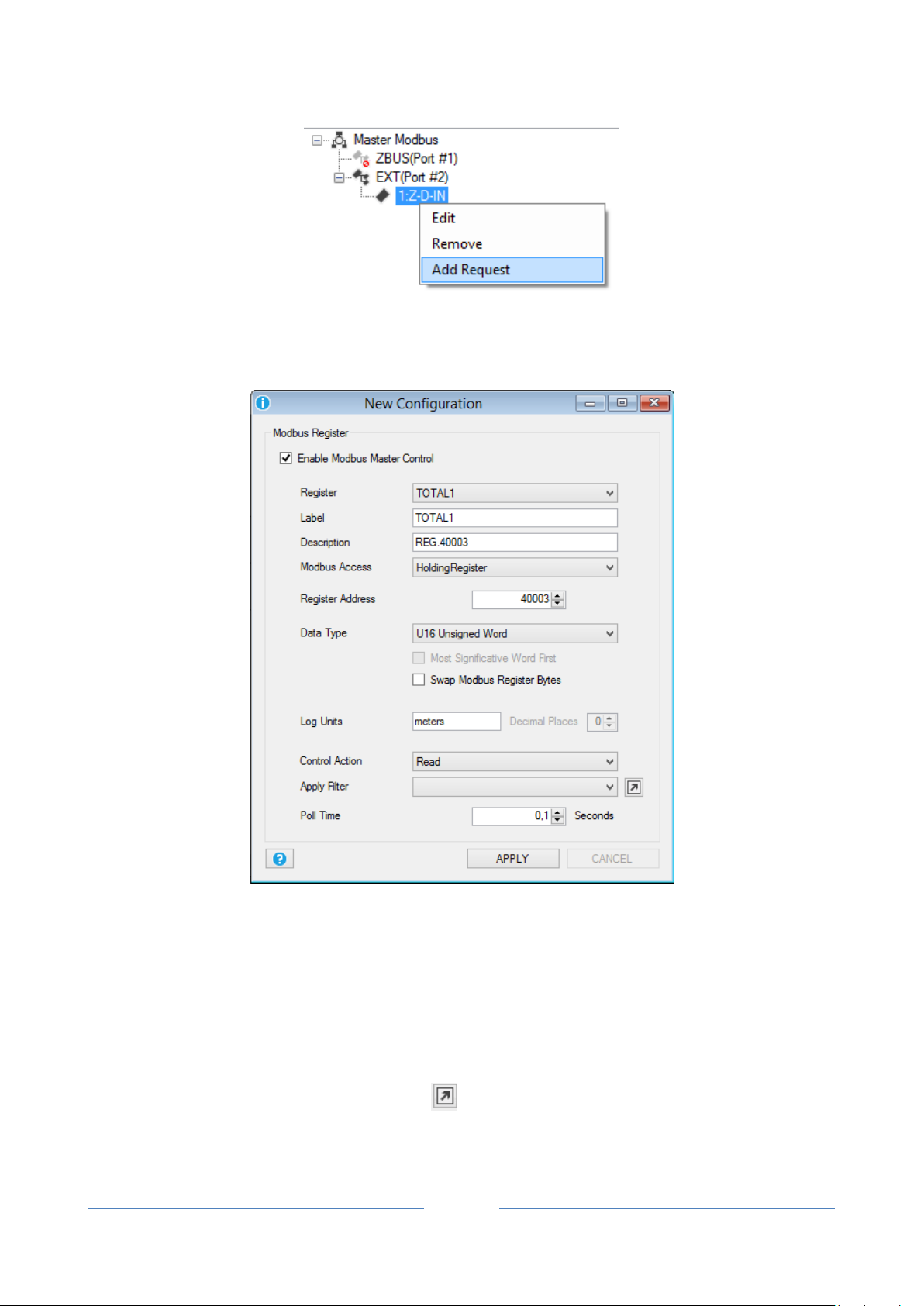
USER MANUAL – Z-GPRS2-SEAL / Z-LOGGER-SEAL
80
Now the registers window will appear:
Select the register from the slave module database (all the others items will be automatically adjusted).
Select the Log Units, the Control Action (register only in Read, or Write) and if you want to add a custom
filter to the register.
You can select up to 16 different filters to apply to a Modbus Value.
Select one of the 16 filters and then push on icon to open the Filters window:

USER MANUAL – Z-GPRS2-SEAL / Z-LOGGER-SEAL
81
Three type of filters are available:
Scale:
The scale filter is used for apply a scale factor to the Modbus value, the filter result is obtained by the
relation:
Average:
The average filter is used for obtaining a moving average on the selected numbers of samples.
The filter result is obtained by the relation:
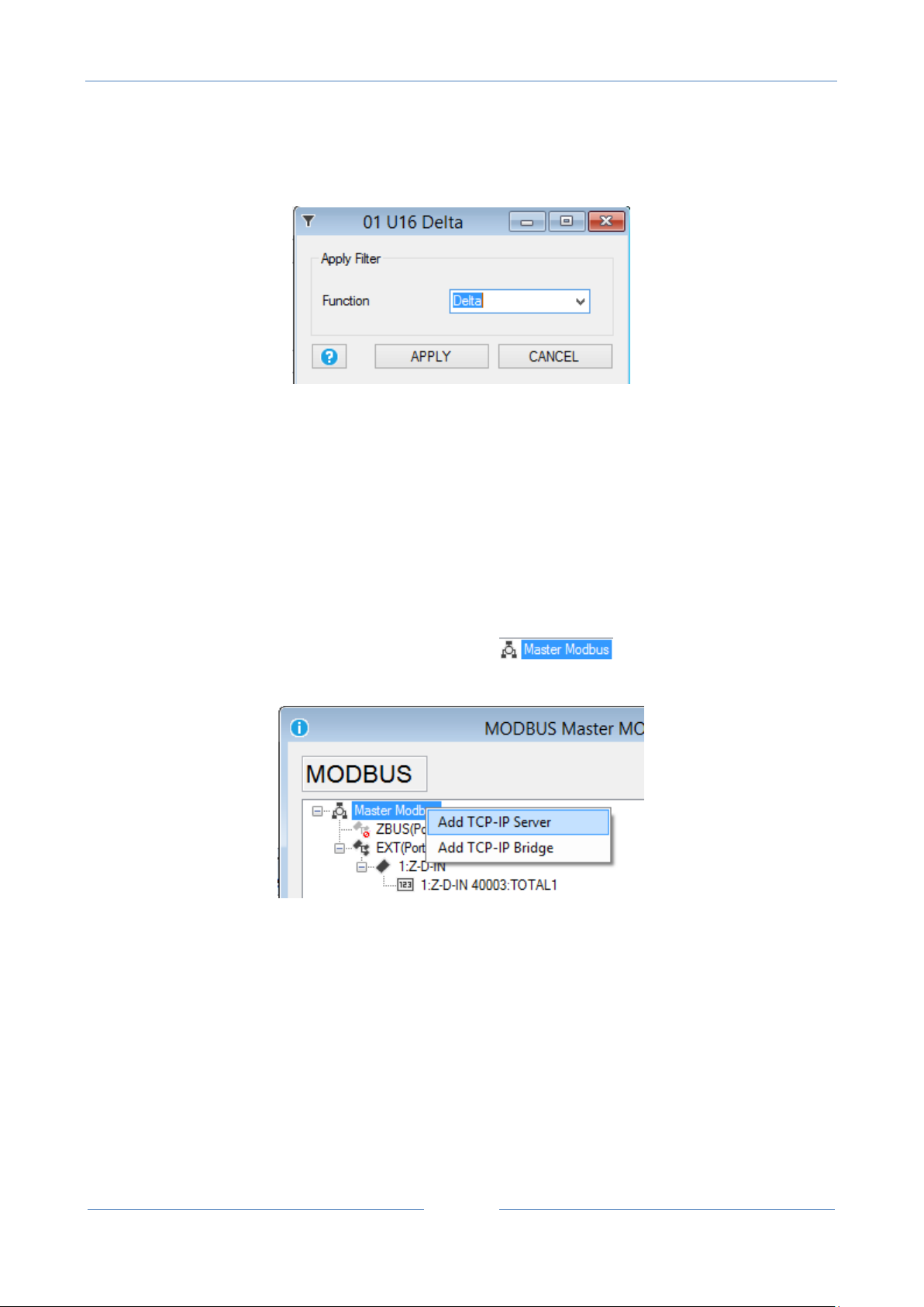
USER MANUAL – Z-GPRS2-SEAL / Z-LOGGER-SEAL
82
Delta:
The delta filter is used for obtaining the difference between two consecutive Modbus Value read.
The filter result is obtained by the relation:
Poll Time: is the Register Polling time (request time or refresh time).
For adding a Modbus TCP-IP node you must select the icon and press the right button
mouse, then select Add TCP-IP Server:
The Modbus TCP-IP Server window will appear:
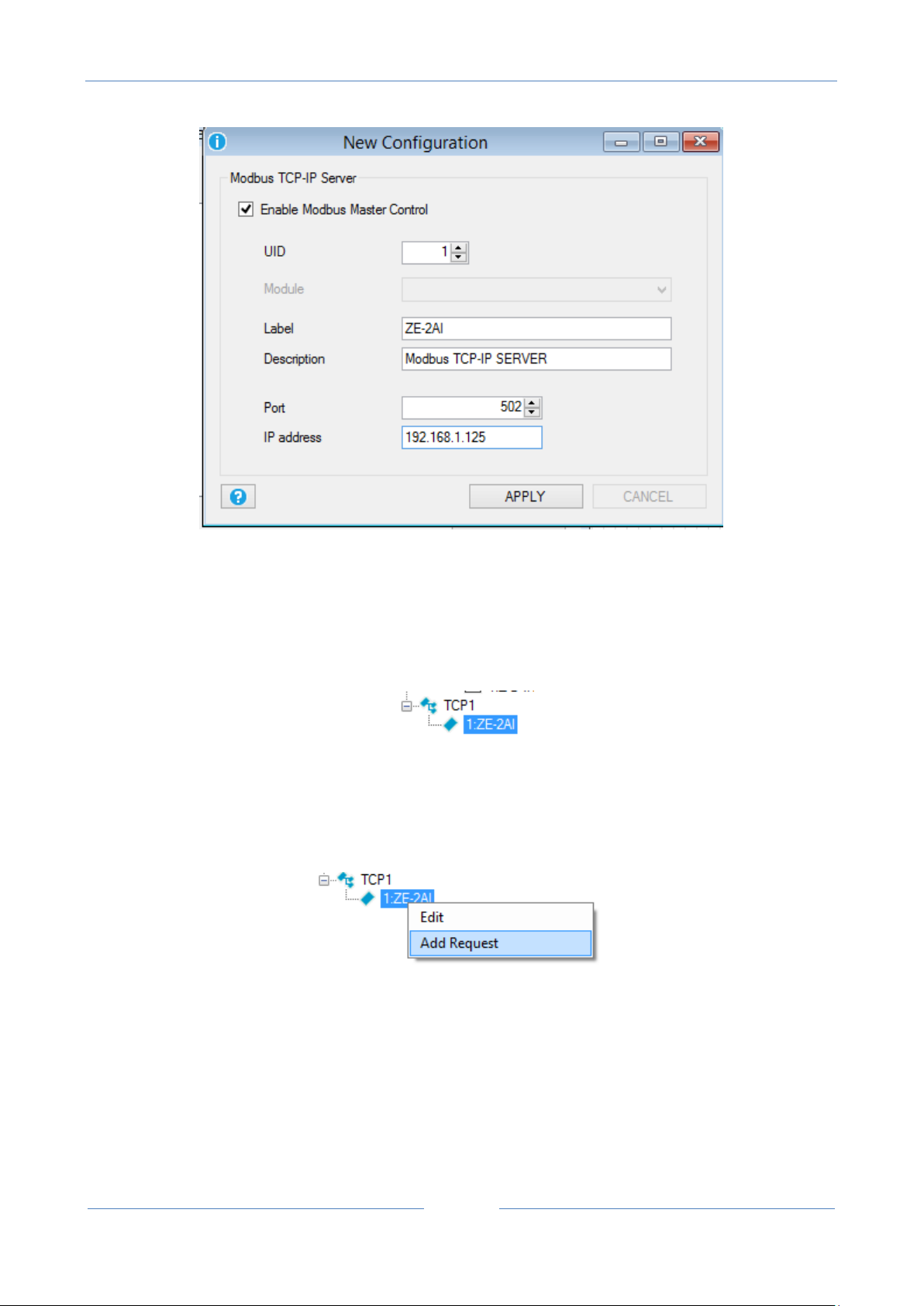
USER MANUAL – Z-GPRS2-SEAL / Z-LOGGER-SEAL
83
Select the Modbus TCP-IP Server UID (unit id or node id), then enter a Modbus Server label.
You must setup also the TCP-IP port (default for Modbus TCP-IP is 502) and the Modbsu TCP-IP Server IP
address.
Now the new Modbus TCP-IP Server is added:
Now we must add the Registers to read from the server, so select the Modbus TCP-IP Server and press the
right button mouse and select Add Request:
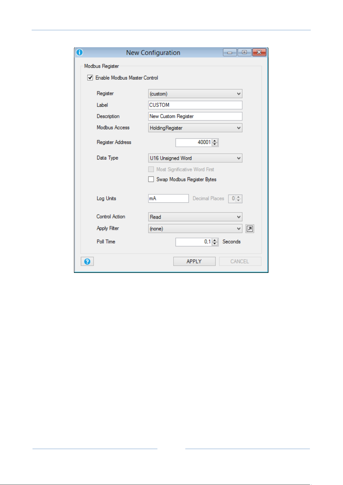
USER MANUAL – Z-GPRS2-SEAL / Z-LOGGER-SEAL
84
Now the registers window will appear:
Select Register “Custom”, the Modbus Access (Modbus function) to use and the Data Type. The others
items are the same of the Modbus serial RTU setup.
12.6. Data Logger Window
General
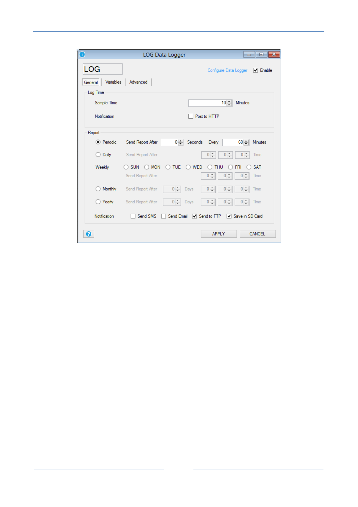
USER MANUAL – Z-GPRS2-SEAL / Z-LOGGER-SEAL
85
The Data Logger configuration can setup which TAG must be logged, how often acquire and how often send
data to the cloud.
Sample Time: is how often all the TAGs must be logged.
Post to Http: if checked send data to the http server every time there is a new log available (available only
on GPRS connection).
Periodic Report: if selected send data to cloud every selected minutes.
Daily Report: if selected send data to cloud every day at the selected hour.
Weekly: if selected send data to cloud each day/days selected at the selected hour.
Monthly: if selected send data to cloud every selected day of the month at selected hour.
Yearly: if selected send data to cloud the selected day of the year at selected hour.
NOTE
All counters inputs are sampled approximately every 5 ms, filtered at 15 ms.
All analog inputs are always sampled every 50 ms.
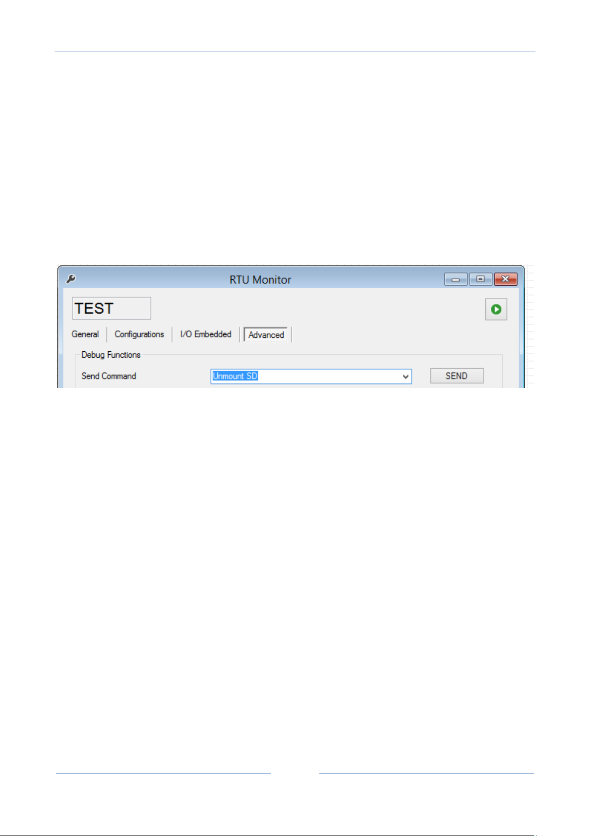
USER MANUAL – Z-GPRS2-SEAL / Z-LOGGER-SEAL
86
When the analog input avearge, maximum or minimum TAG are selected, the values are calculated in the
Sample Time at the speed of 50 ms, so the RTU can log analog events >50ms.
Notification: Select how the notification data must be send to the cloud: SMS, E-mail or FTP.
You can also save a backup of the csv file to the microSD card (the RTU will save the files to the /log
directory). This files can be extracted activating the internal RTU FTP server or extracting the microSD card.
The Log notification to SMS only send the last log value.
CAUTION!
Before extract the microSD you must Unmount-it or the stored data can be unusable!
Variables
In this window you can select which TAGs must be logged, the TAGs can be from embedded or from
external (Mobdus) I/O.
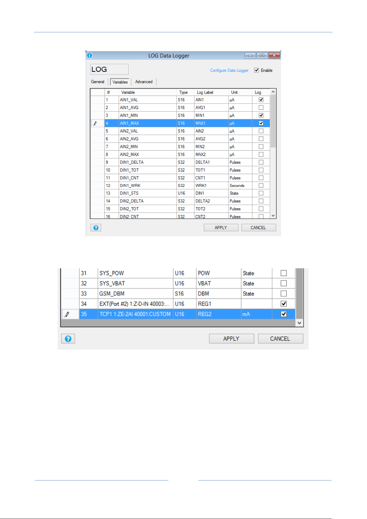
USER MANUAL – Z-GPRS2-SEAL / Z-LOGGER-SEAL
87
Select the TAGs that you want to log by flagging the Log column, Double click on the “Log label” column for
changing the variable label. The Modbus Tags are at the end of the window:
Note that if you have applied a filter to the modbus value only the filter output value will be logged.
A brief embedded I/O variable description is:
Analog Inputs
AINx_VAL is the analog input x value sampled.
AINx_AVG is the analog input x average value calculated in the sample time, the analog input acquisition
speed is 50 ms.

USER MANUAL – Z-GPRS2-SEAL / Z-LOGGER-SEAL
88
GSM Signal
GSM signal [dBm]
0 (MINIMUM)
-115
1
-106 2 -97 3 -88 4 -79 5 -70
6
-61
7 (MAXIMUM)
-52
AINx_MIN is the analog input x minimum value calculated in the sample time, the analog input acquisition
speed is 50 ms.
AINx_MAX is the analog input x maximum value calculated in the sample time, the analog input acquisition
speed is 50 ms.
Digital Inputs
DINx_DELTA is the counter x difference between the last sampled value and the actual sample.
DINx_TOT is the total counter x sampled value.
DINx_CNT is the partial counter x sampled value.
DINx_WRK is the input x work time sampled (how many time the input is been ON or OFF).
DINx_STS is the digital input x sampled status value (1=ON or 0=OFF).
Digital outputs
DOUTx_STS is the digital output x sampled status value (1=ON or 0=OFF)
Misc:
SYS_POW is the main power status (1= main power ok, 0 = main power down)
SYS_VBAT is the battery charge status (1 = battery charge ok, 0 = battery charge low)
GSM_DBM is the GSM value in dBm, the field value can be obtained by the following table:
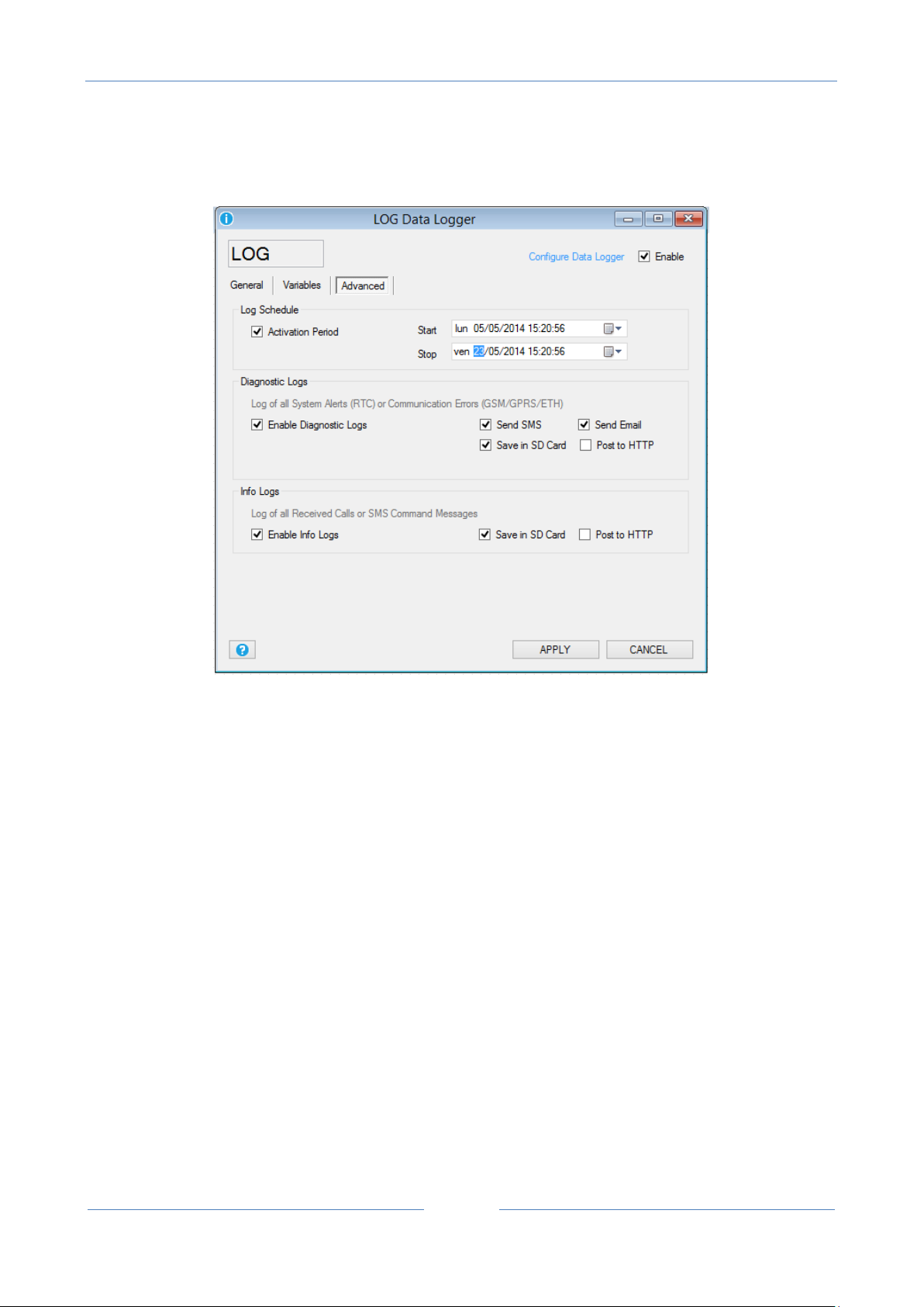
USER MANUAL – Z-GPRS2-SEAL / Z-LOGGER-SEAL
89
Advanced
Activation Period: If checked enable the start date and a stop date of the datalogger, if disabled the
datalogger is always on.
Enable Diagnostic Logs: If checked enable the logging of all the RTU status (Errors, Firmware update status,
Remote configuration update etc…). Select also how the notification can be sent to the cloud (SMS, E-mail
or by a GPRS connection a Post to an HTTP server). Also select if you want to log all the diagnostics to the
microSD (the log file is syslog.csv into the microSD root).
Enable Info Logs: If checked enable the logging of all the RTU command received. Select if you want to log
all the info to the microSD (the log file is syslog.csv into the microSD root) or you can also send a post to the
HTTP server (GPRS connection only).
12.7. Application Window
General

USER MANUAL – Z-GPRS2-SEAL / Z-LOGGER-SEAL
90
RTU Name: Insert the RTU name
Application Name: Insert the application name
Add Timestamp to Messages: If checked add the Timestamp to the SMS or E-MAIL alert notifications. If the
SMS is another RTU (machine to machine communication) you must uncheck this item.
Add RTU Name to Messages: If checked add the RTU name to the SMS or E-MAIL alert notifications. If the
SMS is another RTU (machine to machine communication) you must uncheck this item.
Ring Action: Select the PRG1 and PRG2 action to execute when a ring from an authorized user is received
from the RTU. Select also if the RTU must send an acknowledge when the commands are executed. This
feature can be used for obtain a “zero cost” command.
Separators: Select the separators used into the log csv file: CSV separator (default “;”), Decimal separator
(default “,”), Date separator (default “/”), Time separator (default “:”).
Fast SMS Commands
In this window you can configure at least 16 custom fast commands , each command can be associated to a
short SMS text from “0” to “15”.
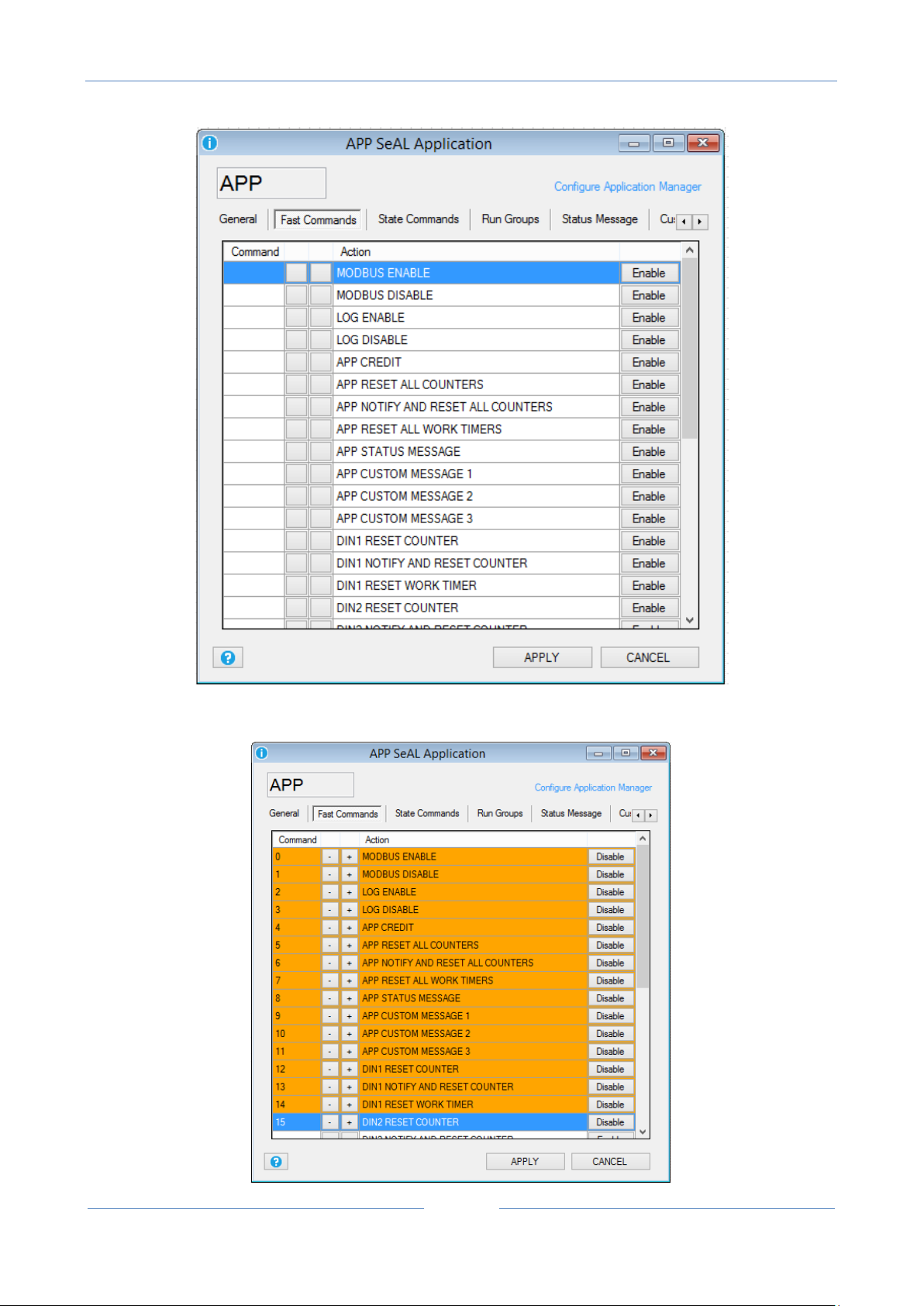
USER MANUAL – Z-GPRS2-SEAL / Z-LOGGER-SEAL
91
Select the “Enable” button for selecting the Command to enable from the commands database:

USER MANUAL – Z-GPRS2-SEAL / Z-LOGGER-SEAL
92
No you can select the SMS text with the icons.
State Commands
This window can be used for customizing the State command 1 to state command 4:
Select the PRG1 or PRG2 command (defined in the General section) or/and the Digital Out function.
Select also the Run groups that you want to activate or not.
When you enable the app state commands you’ll find into the Fast Commands section:

USER MANUAL – Z-GPRS2-SEAL / Z-LOGGER-SEAL
93
Run Groups
When you drag and drop one or more event controls in the graph panel you can select the run group
associated:

USER MANUAL – Z-GPRS2-SEAL / Z-LOGGER-SEAL
94
After that you’ll find the run group configuration in the Run Group section:
In this example EC1 is configured in the run group1, EC2 in the run group2.
You can change the run group directly from the Run Groups window by drag and drop the icon to
the Group 2:
So EC1 and EC2 now are in the same rungroup.

USER MANUAL – Z-GPRS2-SEAL / Z-LOGGER-SEAL
95
Rungroups can be enabled/disabled by the state commands window.
Status Message
In this window you can select which tags must be sent in the status message:
CAUTION!
The status message can be sent also by SMS so you must consider that the SMS text limit is 160 chars.
Custom Message1..3
In this window you can select the TAGs for custom message 1, custom message 2 and custom message 3.
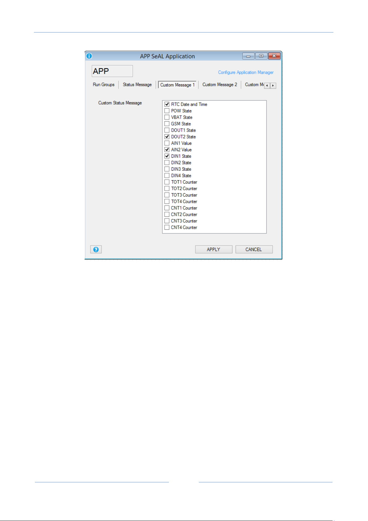
USER MANUAL – Z-GPRS2-SEAL / Z-LOGGER-SEAL
96
Advanced
In this window you can select witch section enable/disable into the debug log. The debug log is obtained by
the Debug serial port.
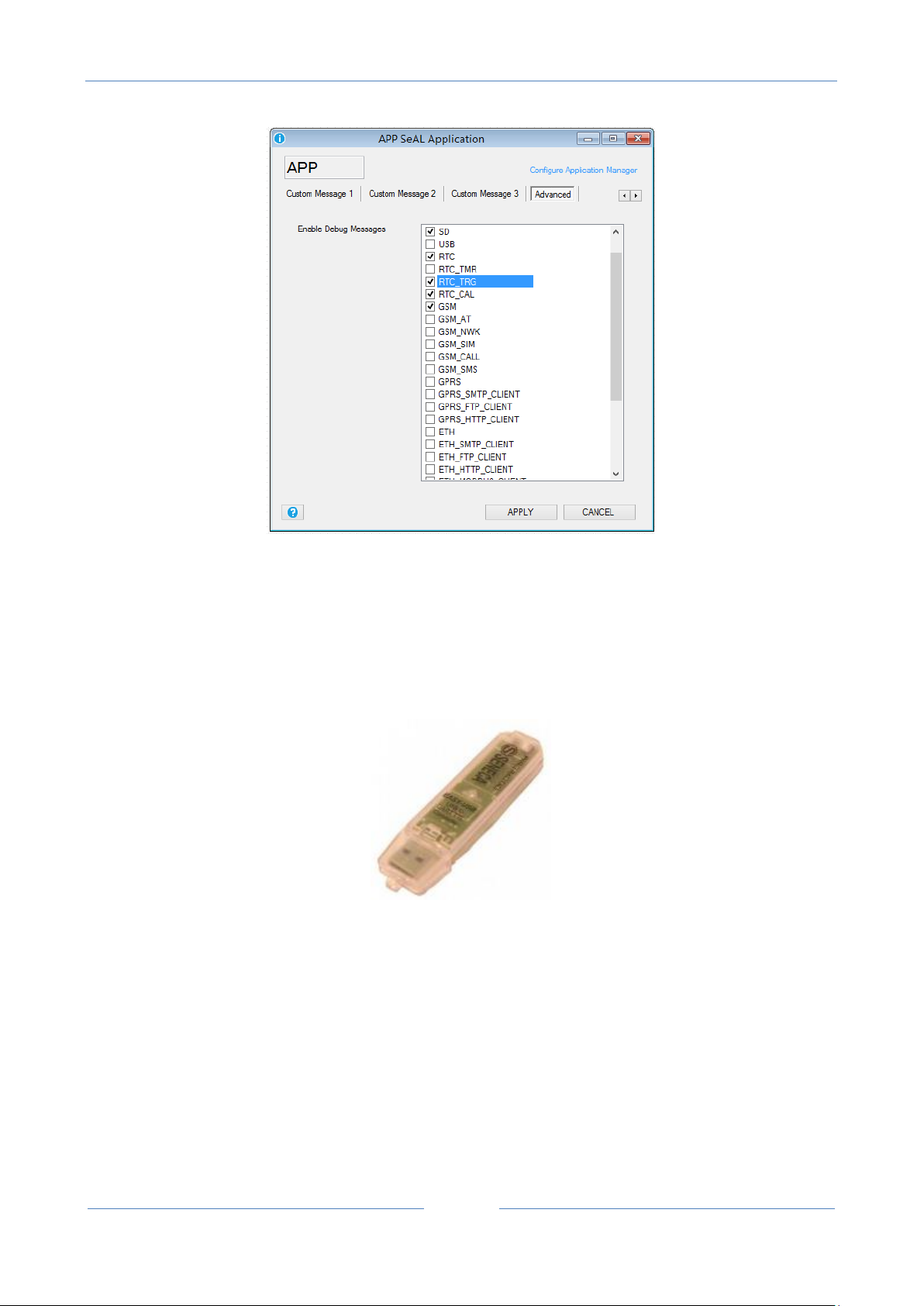
USER MANUAL – Z-GPRS2-SEAL / Z-LOGGER-SEAL
97
Using the debug port, you can view and save to a file a log of operations performed by the RTU.
To connect to the debug port you must use the USB adapter "Easy USB", buy-it directly on the site Seneca
(www.seneca.it) or contact Seneca for more info:
The connection to the PC is performed by a terminal software (for example HyperTerminal) with the
following configurations:
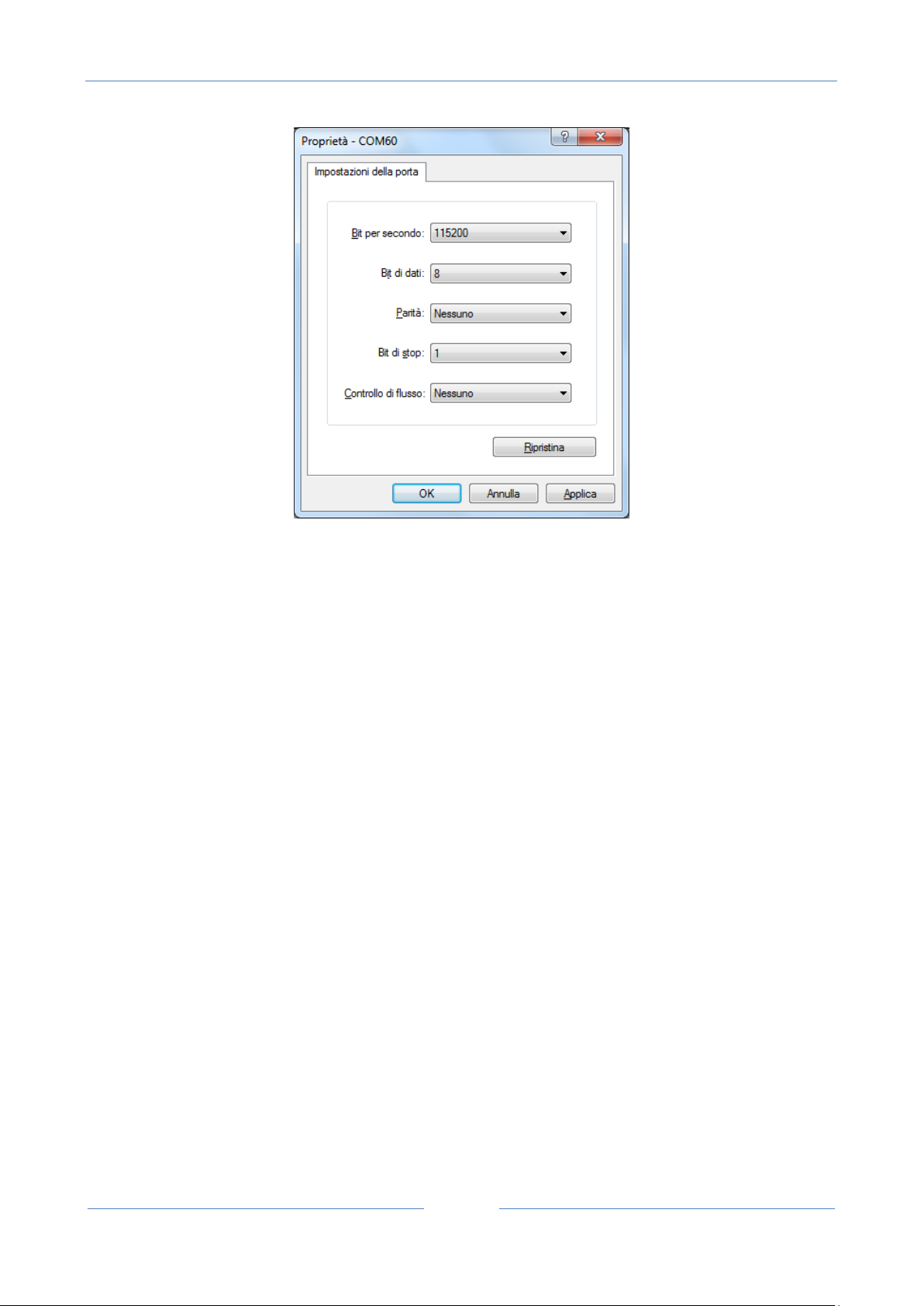
USER MANUAL – Z-GPRS2-SEAL / Z-LOGGER-SEAL
98
12.8. System Management Configuration Window
Blackout
The RTU include a battery for UPS mode, so the RTU can send an alert on main power fail.
After a Blackout the RTU will:
-If configured send alerts
-If configured close the microSD file log
-switch off automatically
When the main power return to work correctly the RTU will switch on automatically.
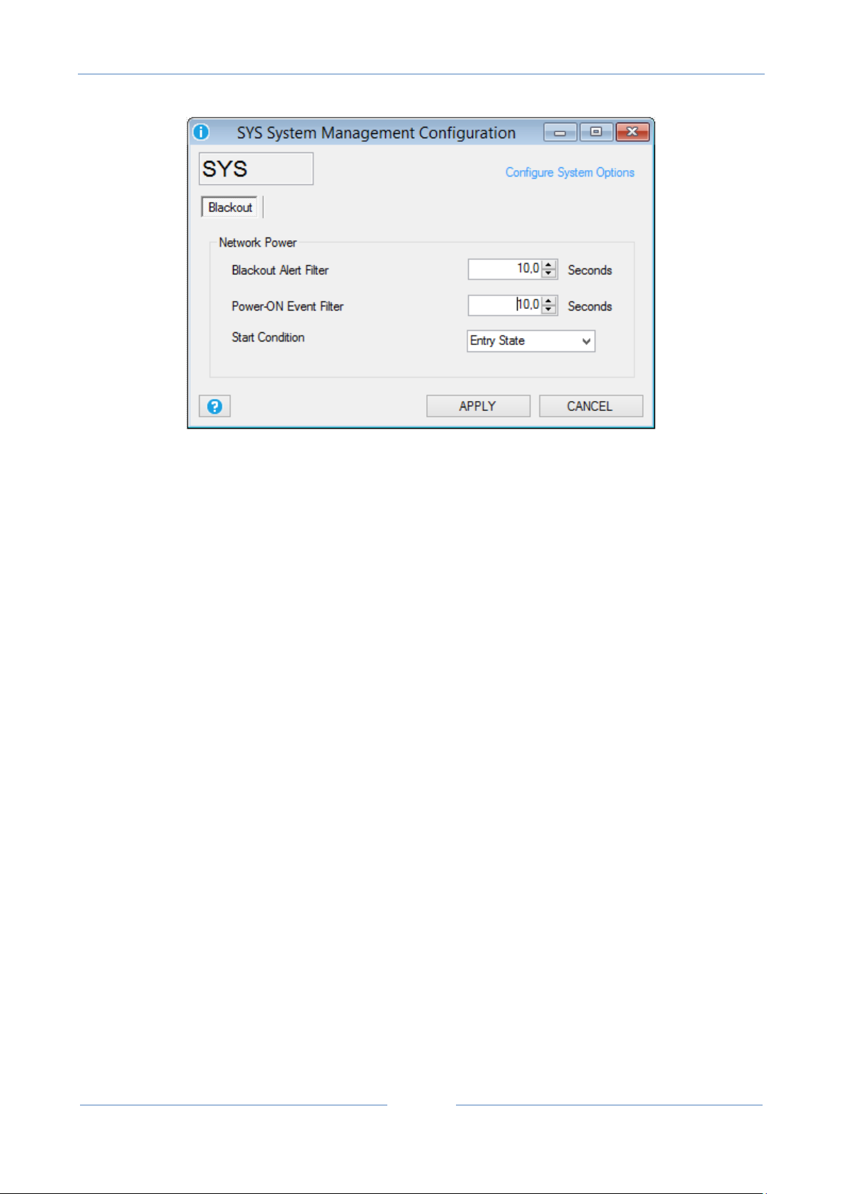
USER MANUAL – Z-GPRS2-SEAL / Z-LOGGER-SEAL
99
Blackout Alert Filter: Select for how much seconds the main power must continuously be down before the
RTU send an alert of blackout.
Power-ON Event Filter: Select for how much seconds the main power must continuously be up before the
RTU send an alert of blackout off. Use this function also for send an alert when the RTU is powered on.
Start Condition: Select the start state and/or the alert mode:
Ignore state: the alert is activated on condition change state
Entry state: the alert is activated on state (so there is no need of a change state)
False: At startup the RTU alert is on False state so if the alert source was True the alert is activated,
otherwise if at startup the alert source was False the alert is activated only at a following alert source
change state.
True: At startup the RTU alert is on True state so if the alert source was True the alert is activated only at a
following alert source change state, otherwise if at startup the alert source was False the alert is activated.
12.9. Analog Input Configuration Window
General
This window configure the embedded RTU analog inputs channels.

USER MANUAL – Z-GPRS2-SEAL / Z-LOGGER-SEAL
100
Analog Input Type: Select the analog input type from current (from 0 to 20 mA) or voltage (from 0 to 30 V).
Measure Average Filter: Select the filter applied to the analog input, a moving average is used for a best
input stability.
Input Scaling: Scale directly the value obtained by the external sensor connected to the analog input.
In the example above you can see how to scale a linear temperature input sensor from 4 ÷ 20mA to -10°C ÷
+100°C.
CAUTION!
If the Input scaling is activated, the datalogger will log the scaled input value and not the raw (mA or V)
input. Also the alerts values are referred to the scaled value.
Alerts
In this window you can select the analog input alerts thresholds, each input has 4 different threshold:
Minimum, Low, High and Maximum. Note that the threshold are referred to the scaled value (in this
example is °C):
 Loading...