

Page 1
SENECA s.r.l.
This document is property of SENECA srl. Duplication and reprodution are forbidden, if not authorized. Contents of the present
To use the product safely and effectively, read carefully the following instructions before use. The product must be used only for the use
this is highly unlikely, the author(s) do not take any responsibility for that. Technical features subject to change without notice.
USER MANUAL
Z-DAQ-PID
Universal input with pid controller
Via Austria 26, PADOVA – ITALY
Tel. +39.049.8705355 – 8705359 Fax. +39.049.8706287
Web site: www.seneca.it
documentation refers to products and technologies described in it. All technical data contained in the document may be modified
without prior notice Content of this documentation is subject to periodical revision.
for which it was designed and built. Any other use must be considered with full responsibility of the user. The installation,
programmation and set-up is allowed only for authorized operators; these ones must be people physically and intellectually suitable.
Set up must be performed only after a correct installation and the user must perform every operation described in the installation
manual carefully. Seneca is not considered liable of failure, breakdown, accident caused for ignorance or failure to apply the indicated
requirements. Seneca is not considered liable of any unauthorized changes. Seneca reserves the right to modify the device, for any
commercial or construction requirements, without the obligation to promptly update the reference manuals.
No liability for the contents of this documents can be accepted. Use the concepts, examples and other content at your own risk. There
may be errors and inaccuracies in this document, that may of course be damaging to your system. Proceed with caution, and although
Technical assistance: supporto@seneca.it (IT), support@seneca.it (Other)
Commercial reference: commerciale@seneca.it (IT), sales@seneca.it
(Other)
MI003419
MI002642-E

USER MANUAL – Z-DAQ-PID
2
INPUT
Number
1
Resolution
15 bits
Sampling time
Configurable between: 5 ms (“Fast”, no rejection), 16.66 ms
(rejection to 60 Hz) or 20 ms (rejection to 50 Hz)
Filter
Configurable between: 0 (no filter is applied), from 1 (min) to 19
(max)
Response time
Sampling time + 6 ms
Voltage-type IN
Scale range is configurable: from 0 V to 10 V. Input
impedance:>5M
Current-type IN (mApassive module/mAactive module)
Scale range is configurable: from 0 mA to 20 mA. Internal shunt:
50It’s possible to power the sensor by: itself (mA-passive module)
or module (mA-active module) using #7 screw terminal (max 25 mA
to max 17 V, short-circuited protected)
Seneca Z-PC Line module: Z-DAQ-PID
The Z-DAQ-PID module acquires one universal input signal (voltage, current, potentiometer,
thermo-couple, thermo-resistance, m-voltmeter) and converts it to an analog format (with PID
regulation).
General characteristics
Three operating mode: conversion with PID regulator, conversion without PID regulator, manual
(constant output configurated through ModBUS register)
Two output types: analog or ON/OFF (time of high-state digital signal is directly proportional to
the analog signal)
Universal input: voltage, current, potentiometer, thermocouple (TC), RTD (Resistance
Temperature Detector) , m-voltmeter
Analog Output: voltage type, active current type, passive current type
Slew-rate, burn-out, output limiters setup
Modbus address and baudrate configurable by Dip-Switches
1. Features

USER MANUAL – Z-DAQ-PID
3
Potentiometer-type IN
Scale range is configurable: from 1 k to 100 k (with parallel
resistor R=330 to connect externally). Excitation current:1 mA.
Input impedance:>5M
Thermocouple-type IN
For TC type: J, K, R, S, T, B, E, N. Input impedance:>5 M.
Automatic detection if a TC interruption occurs
RTD-type IN
For RTD type: PT100, PT500, PT1000, NI100. Resistance measure
(for 2,3 or 4-wires connection) and wire-resistance measure (for 3,4wires connection). Excitation current: 1.1 mA (PT100) and 0.11
mA(PT1000, PT500). Automatic detection if a wire or RTD
interruption occurs
Millivoltmeter-type IN
Scale range is configurable: from -10 mV to 80 mV. Input
impedance:>5 M
Errors related to max
measuring range
Accuracy
Thermal
stability
Linearity error
EMI
Voltage or current-type
input
0.1%
0.01%/°K
0.05%
<1% (2)
TC-type input:
J,K,E,T,N
0.1%
0.01%/°K
0.2°C
<1% (2)
TC-type input:R,S
0.1%
0.01%/°K
0.5°C
<1% (2)
TC-type input:B (3)
0.1%
0.01%/°K
1.5°C
<1% (2)
Cold junction
compensation (for TCtype input)
2°C between
0-50°C
/ / /
POT-type IN
0.1%
0.01%/°K
0.1%
<1%
RTD-type IN (4)
0.1%
0.01%/°K
0.02% (if t>0°C)
0.05% (if t<0°C)
<1% (5)
(1) For the input scale ranges, see “Connections”
(2) Influence of wire resistance: 0.1 V/
(3) Output zero if t<400°C
(4) For RTD type: PT100, PT500, PT1000, NI100. All the errors have to be calculated with
reference to resistive value
(5) Influence of wires resistance: 0.005%/, max20

USER MANUAL – Z-DAQ-PID
4
OUTPUT
Number
1
Resolution
14 bit
Signal-amplitude
limiting
The output signal can be amplitude-limited by an “output limiter”
Voltage-type OUT
Configurable between: 0-5 V, 0-10 V (with minimum load resistance:
1 k). Saturation value: 10.5 V
Current-type OUT
(active or passive)
Configurable between: 0-20 mA, 4-20 mA (with maximum load
resistance: 600 ). Saturation value: 21 mA. “Active current” =the
output: already powered on, needs to be connected to the passive
module; “passive current” =the output: powered off, needs to be
connected to the active module
Errors related to max
measuring range
Errors related
to max
measuring
range
Accuracy
Thermal
stability
Linearity
error
Voltage-type OUT
0.1%
0.01%/°K
0.01%
<1%
Voltage-type OUT
(active or passive)
0.1%
0.01%/°K
0.01%
<1%
CONNECTIONS
RS485 interface
IDC10 connector
RS232 interface
Jack stereo 3.5 mm connector: plugs into COM port
1500 Vac ISOLATIONS
Between: power supply, ModBUS RS485, analog input,
analog output

USER MANUAL – Z-DAQ-PID
5
POWER SUPPLY
Supply voltage
10 – 40 Vdc or 19 – 28 Vac (50Hz - 60Hz)
Power
consumption
Min: 0.5 W; Max: 2 W
The power supply transformer necessary to supply the module must comply with EN60742
(Isolated transformers and safety transformers requirements).

USER MANUAL – Z-DAQ-PID
6
TC-type
Scale range
TC-type
Scale range
J
-210°C..1200°C
S
-50°C..1768°C
K
-200°C..1372°C
R
-50°C..1768°C
E
-200°C..1000°C
B
250°C..1820°C
N
-210°C..1300°C
T
-200°C..400°C
RTD-type
Scale range
RTD-type
Scale range
PT100
-210°C..650°C
PT1000
-200°C..210°C
2. Connections
For potentiometer input connection: you must add externally a R=330 , P=1 k-
100 k
3. Temperature Input Ranges
The input rages are shown in the following tables for Thermocouple:
The input scale range values, for RTD are shown in the following table.

USER MANUAL – Z-DAQ-PID
7
PT500
-200°C..750°C
NI100
-60°C..250°C
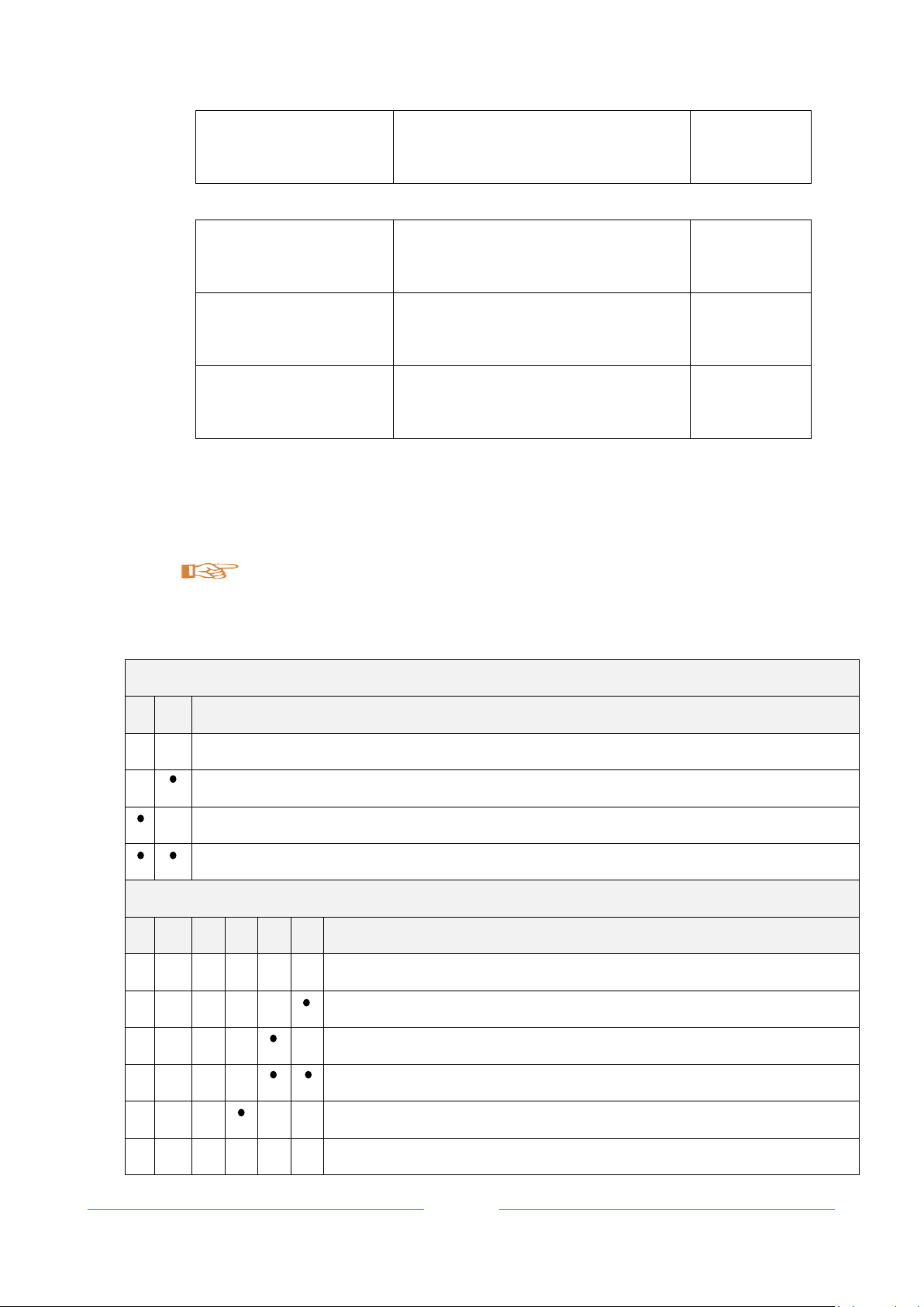
4. Operation Modes
There are six possible functioning modalities for the Z-DAQ-PID, with reference to the following
figure:
- conversion with PID, analog output
- conversion with PID, ON/OFF output
- conversion without PID, analog output
- conversion without PID, ON/OFF output
- manual (constant output), analog output
- manual (constant output), ON/OFF output
With reference to the following figure, the lowest part shows the Z-DAQ-PID setting procedure in
three steps: input setting, operating modality setting, output setting.
In particular, there are three operating modes, each of them allows to supply a ON/OFF output or
an analog output:

USER MANUAL – Z-DAQ-PID
8
Operating modality
Description
Conversion with PID
The analog output is a function of the analog input
processed by the PID transfer function. Moreover, analog
output is directly proportional to the analog input
Conversion without PID
The analog output is directly proportional to the analog
input
Manual
(constant output without
PID)
The analog output is input-indipendent. Anyhow, the input
is acquired and can be found in the RS485 registers (only
reading)
Out type
Description
Analog
OUT is an analog signal
ON-OFF
(see the following figures)
OUT is a ON/OFF signal. High state output is OUT-ES,
low state output is OUT-SS
Slew rate allows to limit the slope of the signal (see reg.40031 and 40032) and burn-out allows to
overwrite the OUT-Fault value (reg.40020, 40021) to the reg.40105, 40106 (burn-out overwriting
is available only for analog output).
Operating modality is configurable by software or by FunctionMod register (40007.[15:8]), with
reference to the “RS485 registers table”.
There are two output type of Z-DAQ-PID, regardless of operating modality:
If out type is “ON/OFF”, the Z-DAQ-PID module allows to have a ON/OFF output with activation
time tON (time corresponding to the high-state output) directly proportional to OUTL.
To understand the ON/OFF out type functioning, see the following figure.

USER MANUAL – Z-DAQ-PID
9
It is possible to limit upper time of high-state ON/OFF output (reg.40029) and to limit lower time
of low-state ON/OFF output (reg.40030). The cycle time is reg.40028 (constant frequency of
ON/OFF output=1/cycle time).
CONVERSION WITH PID
In “Conversion with PID” operating mode, the output (analog or ON/OFF) is a function of the
analog input processed by the PID transfer function. Moreover, output is directly proportional to
the analog input.

USER MANUAL – Z-DAQ-PID
10
Term
Parameter
Meaning
Register
Proportional
BP
Proportional band
40025
Integral
Ti
Integral time
40026
Derivative
Td
Derivative time
40027
PID regulation allows to incline input signal PV (process value) to SP (set point value) with
particular properties (rise time, overshoot, steady-state error, settling time, etc…). In the following
figure is shown the Z-DAQ-PID module used as PID.
In particular, “e” means the difference between set-point and process-value:
Signal error e = (process value – set point) means PID regulation direct-type (for example: used
for cooling)
Signal error e = (set point – process value) means PID regulation reverse-type (for example: used
for heating)
The PID regulation is described by the following parameters:
where Tsample means the PID sampling time (it is equal to 100ms).
If BP decreases

USER MANUAL – Z-DAQ-PID
11
Proportional action strengths
Proportional action weaknesses
Rise time decreases
Ringing and overshoot increases
Steady-state error decreases
Integral action strengths
Integral action weaknesses
Steady-state error is equal to zero
(if input is a constant value)
Rise time increases
Settling time increases
Derivative action strengths
Derivative action weaknesses
Settling time decreases
Noise is amplified
Description of register
Option/Meaning
Address
Input type
V, mA, %, °C, , mV
(see RS485 register table)
40003
Cold-junction
compensation (if TC-type
input)
0=deactivated
1=activated
40005.8
Input start scale
Value in [V, mA, %, °C, , mV]
40008 (MSW)
40009 (LSW)
Input end scale
Value in [V, mA, %, °C, , mV]
40010 (MSW)
40011 (LSW)
If Ti decreases
If Td increases
5. Setup
Input setting
To set Z-DAQ-PID input characteristics, configure the following registers:

USER MANUAL – Z-DAQ-PID
12
Filter applied to input
signal
0=deactivated
1-19=filtering values
40005.[7:0]
Rejection
0b00=50Hz rejection
0b01=60Hz rejection
0b10=Fast (no rejection)
40006.[9:8]
Description of register
Option/Meaning
Address
Functioning modality
0=Conversion with PID, analog output
1=Conversion without PID, analog output
2=Conversion with PID, ON/OFF output
3=Conversion without PID, ON/OFF
output
4=Manual, analog output
5=Manual, ON/OFF output
40007.[15:8]
Cycle time
Time in [sec/10]
(if output modality=ON/OFF)
40028
Minimum time of highstate ON/OFF output
Time in [sec/10]
(if output modality=ON/OFF)
40029
Minimum time of low-state
ON/OFF output
Time in [sec/10]
(if output modality=ON/OFF)
40030
SlewRate enabling
0=deactivated
1=activated
40031
SlewRate
Value in [%/sec]
40032
PID regulation sign
1=direct-type (example: cooling)
0=reverse-type (example: heating)
40007.[7:0]
Operating mode setting
To set Z-DAQ-PID functioning modality characteristics, configure the following registers:

USER MANUAL – Z-DAQ-PID
13
(if operating modality=conversion with
PID)
Set point
(it corresponds to the
process-value desired)
Value in [%], with reference to the input
scale range
(if operating modality=conversion with
PID)
40022 (MSW)
40023 (LSW)
Proportional band (BP)
Value in [%], with reference to the input
scale range
(if operating modality=conversion with
PID)
40025
Integral time
Time in [sec/10]
(if operating modality=conversion with
PID)
40026
Derivative time
Time in [sec/10]
(if operating modality=conversion with
PID)
40027
Offset
Value in [%/100], with reference to the
output scale range
(if operating modality=conversion with
PID)
40024
Description of register
Option/Meaning
Address
Output type
0=current
1=voltage
40004.8
Output current type
0=active current (the module supplies
the loop)
1=passive current (the sensor supplies
the loop)
(if output type is current)
40004.12
Output start scale
Value in [V, mA]
40012 (MSW)
40013 (LSW)
Output setting
To set Z-DAQ-PID output characteristics, configure the following registers:
USER MANUAL – Z-DAQ-PID
14
Output end scale
Value in [V, mA]
40014 (MSW)
40015 (LSW)
Output limiter enabling
0=deactivated
1=activated
40004.0
Limit inferior of the output
limiter
Value in [%], with reference to the output
scale range
40018 (MSW)
40019 (LSW)
Limit superior of the
output limiter
Value in [%], with reference to the output
scale range
40016 (MSW)
40017 (LSW)
BAUD-RATE (Dip-Switches: SW1)
1 2 Meaning
Baud-rate=9600 Baud
Baud-rate=19200 Baud
Baud-rate=38400 Baud
Baud-rate=57600 Baud
ADDRESS (Dip-Switches: SW1)
3 4 5 6 7 8 Meaning
Address and Baud-Rate are acquired from memory(EEPROM)
Address=1
Address=2
Address=3
Address=4
X X X X X X ……………………
6. Dip-switches table
In the following tables: box without circle means Dip-Switch=0 (OFF state); box with
circle means Dip-Switch=1 (ON state).

USER MANUAL – Z-DAQ-PID
15
Address=63
RS485 TERMINATOR (Dip-Switches: SW2)
1 2 Meaning
RS485 terminator disabled
RS485 terminator enabled
7. Modbus RTU protocol
All registers are “Holding register” (Read Modbus function 3) with the convention that the first register is
the 40001 address.
The following Modbus functions are supported:
Read Single Modbus Register (function 3)
Write Single Modbus Register (function 6)
Write Multiple Modbus Registers (function 16)
All values in 32bits are stored into 2 consecutive registers, for example:
If a floating point 32 bits is stored into registers 40135 and 40136, the Most significant word is the register
40135, the less significant word is the 40136.
So the 32bits value is obtained by the following relation:
Abbreviation used
In the following table this abbreviations are used:
“MS” = Most significant
“LS” = Less significant

USER MANUAL – Z-DAQ-PID
16
Name
Range
Interpretation of
register
R/W
Default
Address
MachineID
/
MSB, LSB
R 40001
Id_Code (Module ID)
0x42
Bit [15:8]
Ext_Rev (Module version)
Bit [7:0]
FWREV
/
Word
R 40002
Firmware Code
Errors
/
Bit R
40069
“MSB” = Most significant Byte
“LSB” = Less significant Byte
“MSW” = Most significant Word (16 bits)
“LSW” = Less significant Word (16 bits)
“R” = Read only register
“RW” = Read and write register
“R/W*” = Read and write register (flash store with command register 0xBEEE)
“Unsigned 16 bits” = Unsigned 16 bits register
“Signed 16 bits” = 16 bits register with sign
“Float 32 bits” = Floating point single precision 32 bits (IEEE 754) register
“0x” = Hexadecimal Value
Default communication parameters, RS485: 38400 baud, 8N1.
Default communication parameters, USB: 38400 baud, 8N1.
RS485 register table

USER MANUAL – Z-DAQ-PID
17
These bits aren’t used
/
Bit [15:6]
Over-scale range error for acquired input (over hardware
limits): 0=there isn’t; 1=there is
/
Bit 5
Amplitude detection of acquired input signal: 0=amplitude is
between input start scale and input end scale; 1=amplitude
is less than input start scale
/
Bit 4
Amplitude detection of acquired input signal: 0=amplitude is
between input start scale and input end scale; 1=amplitude
is greater than input end scale
/
Bit 3
Input burn-out error (if bit40006.0=1 and the input is greater
than input scale range): 0=there isn’t; 1=there is.
/
Bit 2
Temperature acquisition error in the thermocouple coldjunctions (if TC-type input): 0=there isn’t; 1=there is
/
Bit 1
Memory loss-of-data: 0=there isn’t; 1=there is
/
Bit 0
Rejection Burn
/
Bit
R/W*
40006
These bits aren’t used
/
Bit[15:10]
Rejection: 0b00=50Hz; 0b01=60Hz; 0b10=No rejection
(“fast” sampling)
0b00
Bit [9:8]
These bits aren’t used
/
Bit [7:1]
Burn-out enabling: 0=deactivated; 1=activated (if 1: fault
output value is overwritten into output register)
0
Bit 0
Filter
Cold-junction
/
Bit, LSB
R/W*
40005
These bits aren’t used
/
Bit [15:9]
Cold-junction compensation (if TC-type input):
0=deactivated; 1=activated
0
Bit 8
Filter applied to the acquired input signal: 0=deactivated;
1=filtering min-value; 19=filtering max-value
0
Bit [7:0]
IN Type
/
Word
R/W*
40003
Input-type: 0=current; 1=voltage; 2=potentiometer; 3=TC J;
4=TC K; 5=TC R; 6=TC S; 7=TC T; 8=TC B; 9=TC E;
10=TC N; 11= 2-wires PT100; 12=3-wires PT100; 13=4wires PT100; 14=2-wires NI100; 15=3-wires NI100; 16=4wires NI100; 17=2-wires PT500; 18=3-wires PT500; 19=4wires PT500; 20=2-wires PT1000; 21=3-wires PT1000;
22=4-wires PT1000; 23=millivoltmeter
0

USER MANUAL – Z-DAQ-PID
18
Address
Parity
/
MSB, LSB
R/W*
40033
Address for RS485 (address of module/node if parameters
are configurated by memory modality): from 0x01=1 to
0xFF=255
1
Bit [15:8]
Parity for RS485: 0=there isn’t; 1=even parity; 2=odd
parity
0
Bit [7:0]
Baudrate
Delay
/
MSB, LSB
R/W*
40034
Baud-rate for RS485 (baud-rate of module/node if
parameters are configurated by memory modality): 0=1200;
1=2400; 2=4800; 3=9600; 4=19200; 5=38400; 6=57600;
7=115200
38400
Bit [15:8]
Delay for RS485 (delay of communication response: it
represents the number of the pauses(*) between the end of
Rx message and the start of Tx message): from 0x00=0 to
0xFF=255
(*)1 pause=6 characters
0
Bit [7:0]
Function
modality
/
Word
R/W*
40007
Functioning modality:
0=Conversion with PID, analog output
1=Conversion without PID, analog output
2=Conversion with PID, ON/OFF output
3=Conversion without PID, ON/OFF output
4=Manual, analog output
5=Manual, ON/OFF output
0
Bit [15:8]
IN-SS MSW
See “Input”
FP-32bit_MSW
R/W*
40008
IN-SS LSW
FP-32bit_LSW
R/W*
40009
Input Start Scale: [mA] (if current-type input); [V] (if voltagetype input) [mV] (if millivoltmeter-type input); [%] (if
potentiometer-type input); [°C] (if TC or RTD-type input)
0 [mA]
IN-ES MSW
See “Input”
FP-32bit_MSW
R/W*
40010

USER MANUAL – Z-DAQ-PID
19
IN-ES LSW
FP-32bit_LSW
R/W*
40011
Input End Scale: [mA] (if current-type input); [V] (if voltagetype input or millivoltmeter-type input); [%] (if potentiometertype input); [°C] (if TC or RTD-type input)
20 [mA]
IN Percent
MSW
Between:0-1
FP-32bit_MSW
R 40110
IN Percent
LSW
FP-32bit_LSW
R 40111
Percent measure of input: [%] with reference to the Input
Scale range (for selected input-type) (if it is equal to 0, it
corresponds to the 0% of the Input Scale range; if it is equal
to 1, it corresponds to the 100% of the Input Scale range)
/
mA MSW
FP between: IN-SS, IN-ES
FP-32bit_MSW
R 40091
mA LSW
FP-32bit_LSW
R 40092
Electric measure of input: [mA] (if current-type input)
/
V MSW
FP between: IN-SS, IN-ES
FP-32bit_MSW
R 40093
V LSW
FP-32bit_LSW
R 40094
Electric measure of input: [V] (if voltage-type input)
/
POT MSW
FP between: IN-SS, IN-ES
FP-32bit_MSW
R 40099
POT LSW
FP-32bit_LSW
R 40100
Electric measure of input: [%] (if potentiometer-type input)
/
TC MSW
FP between: IN-SS, IN-ES
FP-32bit_MSW
R 40083
TC LSW
FP-32bit_LSW
R 40084
Electric measure of input: [mV] (if TC-type input) without
cold-junction compensation (if bit40005.8=0), with coldjunction compensation (if bit40005.8=1)
/
TCT MSW
FP between: IN-SS, IN-ES
FP-32bit_MSW
R 40085

USER MANUAL – Z-DAQ-PID
20
TCT LSW
FP-32bit_LSW
R 40086
Electric measure of input: [°C] (if TC-type input) with
compensation
CJ MSW
/
FP-32bit_MSW
R 40079
CJ LSW
FP-32bit_LSW
R 40080
Equivalent electric measure of the cold-junction: [mV] (if
TC-type input)
/
RTDO MSW
/
FP-32bit_MSW
R 40087
RTDO LSW
FP-32bit_LSW
R 40088
Electric measure of input: [] (if RTD-type input)
/
RTD MSW
FP between: IN-SS, IN-ES
FP-32bit_MSW
R 40089
RTD LSW
FP-32bit_LSW
R 40090
Electric measure of input: [°C] (if RTD-type input)
/
3wires-RTD
MSW
/
FP-32bit_MSW
R 40095
3wires-RTD
LSW
FP-32bit_LSW
R 40096
Measure of the wire resistance for 3 wires RTD connection
[] (if RTD-type input)
/
4wires-RTD
MSW
/
FP-32bit_MSW
R 40097
4wires-RTD
LSW
FP-32bit_LSW
R 40098
Measure of the wire resistance for 4 wires RTD connection
[] (if RTD-type input)
/
OUT Type
Limiter
/
Bit
R/W*
40004
These bits aren’t used
/
Bit[15:13]

USER MANUAL – Z-DAQ-PID
21
Output current type: 0=active current (the module supplies
the loop); 1=passive current (the sensor supplies the loop)
0
Bit 12
These bits aren’t used
/
Bit [11:9]
Output type: 0=current; 1=voltage
0
Bit 8
These bits aren’t used
/
Bit [7:1]
Output limiter: 0=deactivated; 1=activated
0
Bit 0
OUT-SS MSW
See “Output”
FP-32bit_MSW
R/W*
40012
OUT-SS LSW
FP-32bit_LSW
R/W*
40013
Output Start Scale: [mA] (if current-type output); [V] (if
voltage-type output)
0 [mA]
OUT-ES MSW
See “Output”
FP-32bit_MSW
R/W*
40014
OUT-ES LSW
FP-32bit_LSW
R/W*
40015
Output End Scale: [mA] (if current-type output); [V] (if
voltage-type output)
20 [mA]
OUT MSW
FP-32bit_MSW
R 40105
OUT LSW
FP-32bit_LSW
R 40106
Output value: [mA] (if current-type output); [V] (if voltagetype output)
/
OUT
Word
R 40109
Output value: [µA] (if current-type output); [mV] (if voltagetype output)
/
OUT-Fault
MSW
FP-32bit_MSW
R/W*
40020
OUT-Fault
LSW
FP-32bit_LSW
R/W*
40021
Fault output value (measure unit is the same of output)
Reg.40105,40106 are equal to reg.40020,40021 if
40069.2=1 (there is input burn-out error) (if out type =
analog)
0 [%]
OUT-Manual
Between: 0; 10000
Word
R/W*
40107
Output manual value [%100] (if it is equal to 0, it
corresponds to the 0% of the Output Scale range; if it is
equal to 10000, it corresponds to the 100% of the Output
Scale range); for selected output-type, see reg.40004 (if
operating modality=manual, constant output)
0 [%]

USER MANUAL – Z-DAQ-PID
22
Lim Inf MSW
FP-32bit_MSW
R/W*
40018
Lim Inf LSW
FP-32bit_LSW
R/W*
40019
Output limiter lower limit (measure unit is the same of
output)
0
(=0 [mA])
Lim Sup MSW
FP-32bit_MSW
R/W*
40016
Lim Sup LSW
FP-32bit_LSW
R/W*
40017
Limit superior of the output limiter (measure unit is the same
of output)
1
(=20[mA])
PID-sign
Bit
R/W*
40007
PID regulation sign: 1=direct-type (cooling); 0=reverse-type
(heating)
0
Bit [7:0]
Proportional
Band
Word
R/W*
40025
PID regulation proportional band [%], with reference to the
Input Scale range (if operating modality=conversion with
PID)
100%
Integral time
Word
R/W*
40026
PID regulation integral time [sec/10]. 0=there is no integral
action (if operating modality=conversion with PID)
2400
[sec/10]
(=240sec)
Derivative time
Word
R/W*
40027
PID regulation derivative time [sec/10]. 0=there is no
derivative action (if operating modality=conversion with
PID)
0 [sec/10]
Set point MSW
FP-32bit_MSW
R/W*
40022
Set point LSW
FP-32bit_LSW
R/W*
40023
Input set point for the PID regulation [%] with reference to
the Input Scale range (if it is equal to 0, it corresponds to
the 0% of the Input Scale range; if it is equal to 1, it
corresponds to the 100% of the Input Scale range) (if
operating modality=conversion with PID)
50%
Process Value
MSW
FP-32bit_MSW
R 40103

USER MANUAL – Z-DAQ-PID
23
Process Value
LSW
FP-32bit_LSW
R 40104
Process value for the PID regulation: [mA] (if current-type
input); [V] (if voltage-type input); [mV] (if millivoltmeter-type
input); [%] (if potentiometer-type input); [°C] (if TC or RTDtype input)
/
Process value
Word
R 40108
Process value for the PID regulation: [µA] (if current-type
input); [mV] (if voltage-type input); [mV/100] (if
millivoltmeter-type input); [%/100] (if potentiometer-type
input); [°C/10] (if TC or RTD-type input)
/
Offset
Word
R/W*
40024
Output offset for the PID regulation [%/100] with reference
to the Output Scale range (if it is equal to 0, it corresponds
to the 0% of the Output Scale range; if it is equal to 1, it
corresponds to the 100% of the Output Scale range) (if
operating modality=conversion with PID)
5000
(=50%)
Slew Rate
enabling
Word
R/W*
40031
Output slew rate: 0=deactivated; 1=activated
1
Slew Rate
Word
R/W*
40032
Output slew rate [%/sec]
100
[%/sec]
Cycle Time
From 1 to 1310
Word
R/W*
40028
Output cycle time [sec/10] (if output modality=ON/OFF)
300
(=30 sec)
MinTime-High
From 1 to 1310
Word
R/W*
40029
Minimum time of high-state output [sec/10] (if output
modality=ON/OFF)
0
(=0 sec)
MinTime-Low
From 1 to 1310
Word
R/W*
40030
Minimum time of low-state output [sec/10] (if output
modality=ON/OFF)
0
(=0 sec)
Command
Command execution
0xC1A0 (decimal 49568) – Execute a hardware reset
0
40068

USER MANUAL – Z-DAQ-PID
24
0xBEEE (decimal 48878) – Save in Flash the actual Setup
(registers with R/W*)
Note: The Flash can be written for a Maximum of 20000
times.
 Loading...