


ST3000
and
X-Vault Xvos
User Guide
XV-AM3U35
XV-AM4U35
V2.0.1
Product revisions covered are 1 & 2
Manual Revision 2.01
4/16/2015
This unit ships with a 30 day temporary use license. The
unit must be correctly licensed to enable permanent
operation and specific features. Please follow chapter titled
“Licensing” to acquire and enter license files.
NOTICE: First and most important level of data protection starts with uninterruptable power.
1

Seneca Data Distributors, Inc. (“Seneca”) reserves the right to make changes to the product described in this
manual at any time and without notice. This product, including software and documentation, is the property of
Seneca and/or its licensors, and is supplied only under a license. Any use or reproduction of this product is not
allowed, except as expressly permitted by the terms of said license.
In no event will Seneca be liable for direct, indirect, special, incidental, speculative or consequential damages
arising from the use or inability to use this product or documentation, even if advised of the possibility of such
damages. In particular, Seneca shall not have liability for any hardware, software or data stored or used with
the product, including the costs of repairing, replacing, integrating, installing or recovering such hardware,
software or data.
Any disputes arising between manufacturer, reseller and customer shall be governed by the laws of the State
of New York, USA. The State of New York shall be the exclusive venue for the resolution of any such disputes.
Seneca’s total liability for all claims will not exceed the price paid for the hardware product.
FCC Statement: This equipment has been tested and found to comply with the limits for a Class A digital
device pursuant to Part 15 of the FCC Rules. These limits are designed to provide reasonable protection
against harmful interference when the equipment is operated in a commercial environment. This equipment
generates, uses, and can radiate radio frequency energy and, if not installed and used in accordance with the
manufacturer’s instruction manual, may cause harmful interference with radio communications. Operation of
this equipment in a residential area is likely to cause harmful interference, in which case you will be required to
correct the interference at your own expense.
Unless you request and receive written permission from Seneca, you may not copy any part of this document.
Information in this document is subject to change without notice. Other products and companies referred to
herein are trademarks or registered trademarks of their respective companies or mark.
2

Page
I. Product Introduction ……………………………………………………………………. 6
II. Intended Audience………………………………………………………………………. 7
III. Best Practices…………………………………………………………………………….. 8
IV. Network Requirements …………………………………………………………………. 12
V. User Interface Orientation …………………………………………………………… 15
VI. Licensing ……………………………………………………………………………… 18
VII. The Process
Create & Modify “The Plan” …………………………………………………….. 21
Configure Ports ………………………………………………………………….. 21
Create Host ………………………………………………………………………. 22
Create RAID Sets ……………………………………………………………….. 22
Create Logical Volumes ………………………………………………………… 22
Backup New Configuration …………………………………………………… 22
Connect Volumes At Host ……………………………………………………… 22
Create File System, Format & Mount Volume ……………………………….. 23
VIII. Location & Addressing
Drive Enclosure Slots And Trays ……………………………………………… 25
i. Drive Tray Identification
ii. Drive Tray Removal
iii. Drive Tray Insertion
Cabling ……………………………………………………………………………. 26
Preset IP Address and Password ……………………………………………… 28
First Time Accessing The Management GUI……………..…………………. 29
iSCSI/NAS Port Configuration ……………………………………………..….. 31
SAS Port Configuration ………………………………………………………… 34
IX. Host Port Management
Finding Windows Server 2008 IQN …………………………………………… 35
Finding VMware 5.x IQN ……………………………………………………….. 36
Three Methods To Connect To iSCSI Server ……………………………….. 36
Creating a CHAP iSCSI Host …………………………………………………. 37
Creating A Mapped & Masked Host ………………………………………….. 38
Creating A Mapped/Masked With CHAP Host ………………………………. 39
Creating A NAS Host …………………………………………………………… 39
Creating A SAS Host …………………………………………………………… 39
X. RAID Management
Creating A RAID Set ………………………………………...…………………. 40
Modifying A RAID Set ………………………………………………………….. 45
Viewing A RAID Set ……………………………………………………………. 46
XI. Volume Management
Preparation For Logical Volume Creation …………………………………….. 48
Creating A Volume ………………………………………………………………. 49
3

Spanning Logical Volume Across RAID Sets ………………………………… 53
Volume IO Port & Host Assignment ………………..……………………… 54
Viewing A Logical Volume …………………………………………………… 57
Modifying A Logical Volume …………………………………………………. 57
Expanding A Logical Volume ………………………………………………… 58
Creating A Thin Volume ………………………………………………………. 59
Thin Provisioning FAQ’s ………………………………………………………. 61
Creating Single Drive Volumes ………………………………………………. 62
XII. Mounting Volumes To Operating System
Attaching iSCSI Volume To Windows Server 2008 ………………………… 64
Entry Point for SAS & iSCSI Volumes Appearing In Disk Manager …….. 68
XIII. Snapshots
Preparing To Create Snapshots ………………….…………………………... 72
Creating A Snapshot …………………………………………………………… 72
XIV. Attaching External ISCSI Storage Appliances ………………………………………. 76
Deletion of Remote iSCSI Disk ……………………………………………….. 77
XV. Replication ………………………………………………………………………………. 79
Creation of Replication set ……………………………………………………... 81
Monitoring Replication …………………………………………………………. 82
XVI. Backup & Restore Of Specific Configuration Settings ……………………………… 84
XVII. Individual Drive Configuration and S.M.A.R.T ………………..……………………… 85
XVIII. Housekeeping
Setting System Name, Time and NTP …………………………………………88
Setting Up SMTP ………………………………………………………………... 88
Creating & Managing Users ………………………………………………….. 90
XIX. Alert Notification ……………………………………………………………………….. 91
XX. Information, Statistics, Status & Errors ………………………………………………. 92
XXI. Update & Diagnostics ………………………………………………………………… 94
XXII. Adding Expansion Enclosures ……………………………………………………….. 95
Naming Enclosures ………………………………………………………….. 96
XXIII. Configuring a SAS SAN ………………………………………………………………. 98
XXIV. Remote Management Through Firewalls ………………………………………….… 100
XXV. UPS Port Configuration ………………………………………………...……………… 101
Appendix A Specifications …………………………………………………………………... 102
Appendix B Main Board connectors and jumpers ………………………………………… 104
Appendix C Revisions & BIOS Settings …………………………………………………… 106
Appendix D Field Replaceable Units (FRU) Parts ………………………………………… 108
4

NOTICE: First and most important level of data protection starts with
uninterruptable power. An Uninterruptable Power Source (UPS) is
required to protect storage data, cache battery backup is not adequate
to the task of data storage protection.
If this Storage Appliance is not protected by an UPS please consult
with your account representative or pre-sales engineer for assistance
in correctly sizing a UPS to not only protect this Storage Appliance but
your entire IT infrastructure.
THE ST3000 and XVOS v2 models are identical. The only difference is
branding and market verticals applied
5
I PRODUCT INTRODUCTION
The X-Vault® Xvos or ST3000 series empowers IT users with both network file level access and block
level access in the same unit. One network attached subsystem provides CIFS and NFS file access as
well as IP SAN connectivity.
The X-Vault Xvos series is available in two rack mount comfigurations.
Xvos V1
3U 4U
Xvos V2 or ST3000
3U 4U
V2 units support SAS 3g and 6g, SATA-II and III and Solid State Drives. V3 units support the
preceding as well as SAS 12g enclosures, controllers, SSD and drives. The 3U supports up to
sixteen internal hot swap drives and the 4U supports up to twenty four internal hot swap drives.. The
3U and 4U X-Vaults are expandable externally up to 128 and 192 total drives respectfully. Both
appliances can be optionally configured to 512 drives.
A quad core 3.3GHz XEON processor provides ample power to drive outstanding IO and bandwidth.
Memory options up to 32GB are available to support high count NAS clients. The standard units ship
with five 1Gbe network ports with four different 10Gbe NIC options and one management port..
Multiple NIC ports, adaptive RAID caching as well as hot swap power supplies provide best in class
performance and reliability.
The Xvault Storage Operating System (XSos) graphical user interface allows easy configuration for
advance features such as volume expansion, storage virtualization, same enclosure mixed tier
support, local and area mirroring, remote replication, snapshots, thin provisioning, NAS client backup,
Backup to Cloud, drive level encryption and block level deduplication.
The Xvos storage appliance can provision in iSCSI, F/C and SAS storage. This feature allows
previously purchased storage investment protection and integratability.
The X-Vault® Xvos platform supports the latest versions of VMwareTM, Microsoft WindowsTM, Citrix
XENTM Server, Red HatTM Linux as well as any operating system that supports a level 2 or higher
iSCSI initiator, NAS, Fibre Channel, FcoE or Infiniband.
6

II INTENDED AUDIENCE
The intended audience for this manual and IP SAN storage product should have a working
knowledge of server hardware and operating systems, a firm grasp of storage area network concepts
as well as the ability to configure managed network switches.
Server Hardware/OS
Have working knowledge of PCIe slot types, slot availability and ability to add
appropriate cards when necessary.
Be familiar with network connectivity and configuration of NIC cards with regard to IP
addressing, teaming, jumbo frames and MTU size.
Have the ability and authorization to add drivers and software components to facilitate
the installation of the IP SAN, F/C SAN, SAN, FcoE or Infiniband subsystem.
Enact a plan for exactly what type of storage will be used, NAS, iSCSI, FcoE, SAS, F/C,
Infiniband or a combination of three different type of physical connection. Along with
this, the ability to create, configure and allocate NAS shares, Mapping and Masking of
F/C, IP and FcoE SAN volumes as well as SAS direct or switched and finally Infiniband
architecture and requirements. The ability to plan for capacity requirements and the
subsequent allocation of logical volumes to network accessed share or block level
connected devices. As well as the formatting and mounting of virtual drives.
Network Hardware
Have a clear understanding of the present LAN/WAN infrastructure and how to plan for
the addition of NAS and/or SAN storage in an IP environment.
Be familiar with LACP and teaming configuration options for Layer2 and 3 managed
switches to be used in the implementation of a NAS or IP/FcoE SAN.
Be familiar with VLAN creation or segmentation of switches to be used in the installation
of NAS and/or IP/FcoE SAN storage.
Have a working knowledge of how to configure network switches or routers to
accommodate remote storage for replication transport or remote sites.
Correctly segment NAS/IP/FcoE SAN traffic between server traffic and/or client traffic.
Xvos/ST3000 Appliance
Be able to create a virtual storage device plan using best practices described in this
manual.
Have the ability to recognize when and what security features should be implemented to
the site requirements.
Correctly assign proper attributes to NAS shares as required by local and remote site
requirements. Including the management of Active directory servers.
7

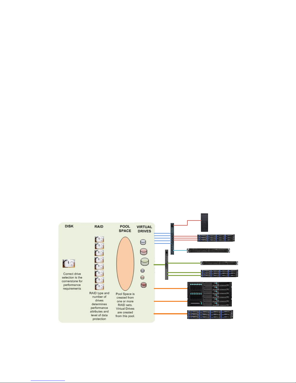
III BEST PRACTICES
DRIVE AND RAID SELECTION CONSIDERATION
RAID type, drives used (15k RPM, 10k RPM, 7200 RPM and SSD) and number of drives in a RAID
set are important considerations when planning your NAS or SAN implementations. There are many
articles available on the network explaining how RAID sets work. This manual will deal with RAID10,
RAID5 and RAID6.
DISK DRIVE PERFORMANCE CONSIDERATIONS
The base all starts with drive selection. In the past, drive categories were 15k RPM SAS, 10k RPM
SAS or 7200 RPM SATA. Today all spindle speeds are available with 6 Gb/s interfaces. Deal
strictly with the drive RPM classification or solid state drives as the performance metric. With regard
to SAS or SATA-III interface, SATA-III drives still have a slight cost advantage over SAS. However,
this initial savings may be mute given some of the SAS feature advantages.
SAS drives are designed by standard to be backward compatible, when SAS 12g
become available, SAS 6g and 3g drives will be be compatible. SATA drives on the
other hand do not have to be backward compatible. This has represented issues as
SATA-I to II to III progression has transpired.
The SAS standard offers better internal configurability, more robust error handling and
reporting.
SAS drives are dual ported and offer multiple paths in the event of controller or cable
failure when used in high availability configurations.
Many SAS/SATA array offerings require a small adapter card between the enclosure
SAS midplane and the SATA drive. SAS disk drive investment is more easily preserved
because SAS drives can be migrated more easily to other platforms. The Seneca Xvos
platform does not require SAS to SATA adapters.
SATA drives still use communication tunneling which inhibits performance.
Drive performance is measure in two ways. Average access time which equals the average seek
time (head positioning) plus average rotational latency (time for the disk to spin 1800 ). I/O’s per
second operations benefit with lower access times. Transfer rate or how fast the data comes off of a
physical disk is determined by bit density and how fast the disk spins.
Drive Avg. Rotational Avg. Read Access Avg. Transfer
Latency Seek Time Rate __
3.5” 7200 4.16ms 8.5ms 12.66ms 112 MB/s
3.5” 15k 2.00ms 3.4ms 5.40ms 241 MB/s
2.5” 7200 4.16ms 7.5ms 11. 66ms 112 MB/s
2.5” 10k 3.00ms 3.7ms 6.70ms 125 MB/s
2.5” 15k 2.00ms 3.1ms 5.10ms 238 MB/s
8

Application Guidelines
< 3000 IO per second 7200 RPM disk drives
3000 > 7000 IO per second 10k or 15k RPM disk drives
> 7000 IO per second Solid State Disks
Performance is subjective. There are tools to measure existing IO. Windows operating systems
provide the “Perfmon” performance monitoring tool. Linux users generally subscribe to dd.
Other best drive/array practices include fragmentation prevention and disk defragmentation.
RAID SET PERFORMANCE CONSIDERATIONS
The most common RAID types in use today are RAID5, RAID6 and RAID10. RAID5 provides best
performance with single drive failure protection. RAID6 performance is only slightly less on read
operation but exacts a 10% to 25% write performance. RAID6 offers up to two drive failures in a
single RAID set. RAID10 was the exclusive domain for database performance. Today’s RAID
controller technology has evened the performance between RAID10 and RAID5 when eight or more
drives are used. When less than eight drives are used in a RAID set the performance advantage
goes to RAID10. RAID10’s best advantage is when the capacity requirement are low and the
performance requirement is high. Four to sixteen drive RAID10 configurations are optimal.
RAID Minimum Maximum
Type Drives* Drives*
10 4 16
5 5 24
6 6 24
*Per RAID Set
Many users are concerned about the data exposure while a drive is down in a RAID5 set, while
waiting for a replacement to arrive and do not wish to pay the write performance penalty of RAID6.
Consider a hot spare or global spare for RAID5, this will reduce the time of exposure to RAID5 failure.
When the cost of a spare drive is weighed against the extra protection afforded, an onsite spare or a
global/hot spare should be considered a best recommendation.
ISCSI VOLUME AND NETWORK PATH RELATIONSHIP
An iSCSI volume is the space earmarked in the storage appliance to be used as a virtual disk
presented to a server (host). The server will assign this virtual logical disk as an actual drive letter or
designation and mount to the system. An iSCSI volume is often referred to as a LUN (logical unit
number)
The iSCSI volume may change network paths because of path failure or load balancing measures
taken by the host operating system or the storage appliance. This requires the server/host OS
feature; MPIO
9

Multiple iSCSI volumes travel across multiple network path when hosts are correctly configured.. The
SYST
PS1
PS2
FAN
STAT
DUPLEX
SPEED
MODE
X2-2
15
X2-1
13
16
14
3
1 2 3 4
3
5 6 7 8
3
9 10 11 12
Catalyst 3560-E Series
VD
2
VD 3VD
4
VD
1
SYST
PS1
PS2
FAN
STAT
DUPLEX
SPEED
MODE
X2-2
15
X2-1
13
16
14
3
1 2 3 4
3
5 6 7 8
3
9 10 11 12
Catalyst 3560-E Series
VD
2
VD
3
VD
4
VD
1
Normal
iSCSI Volumes balanced across all
available 1Gbe Paths
Path Failure
OS MPIO recognizes path failure and
redirects iSCSI Volume to alternate 1Gbe
Path
iSCSI protocol was written when 1Gbe network paths were in development. The iSCSI protocol was
conceptualized with the idea that high I/O’s per second could be achieved with limited bandwidth. As
such using multiple 1Gbe paths would supply the IO capability and bandwidth necessary while still
using commoditized network components. The increased bandwidth of 10Gbe has removed many
sizing restrictions and bandwidth restrictions. It is a best practice to create multiple volumes and
paths to each server. Never restrict a server to a single port, consider two or more IP SAN dedicated
paths to and from a server. This not only increases performance but it also provides path resiliency in
the event of port failure. Server OS Multiple Input Output (MPIO) and load balancing capability is
responsible for port failover and performance increase. The MPIO features must be enabled and
configured.
The maximum mathematical sustained transfer rate per 1Gbe link is 125MB/s (1 Gb/s), higher
transfer rates require more than one iSCSI path. With IP and iSCSI protocol overhead a maximum
transfer rate of 100 MB/s is more realistic. When sustained transfer rate requirements are greater
than 400Mb/s consider a 10Gbe implementation. The Xvos platform can support 10Gbe and 1Gbe
networks simultaneously but they must be connected to separate networks.
MPIO – MULTI POINT INPUT OUTPUT
MPIO is a supported feature on Xvault Xvos Appliances. However it is installed and configured on
the host system. The enablement of this feature is accomplished by defining multiple Ethernet paths
for the iSCSI devices using the iSCSI Initiator on the host system. SAS and Fibre Channel connected
arrays also support MPIO and are managed through the disk management subsystem.
Any server requires more than one path from the Server/Host (NIC port, SAS x4 connection or Fibre
Channel port) to the Storage Appliance to support MPIO.
MPIO should always be installed and configured on host servers through iSCSI Initiator for an
IP/FcoE SAN or Disk Manager for SAS. MPIO is considered a must for performance to transcend the
single 1Gbe port performance barrier. 10g iSCSI, SAS and Fiber Channel have higher bandwidths
resulting in less of a performance difference then configuring multiple 1Gbe ports.
10
2.4 GBs SAS link
Dual Path
4.8 GBs SAS link
Single iSCSI or NAS
MPIO iSCSI
NAS
10Gbe iSCSI, NAS or FCoE
Jumbo Frames must be
implemented on Server NICs,
Switches and Storage
Appliances
MPIO increase path
resiliency and
performance.
iSCSI, FCoE and SAS volumes
appear to the server as direct
attached disks
JUMBO FRAMES
Jumbo frames are Ethernet frames with more than 1500 bytes of payload. Jumbo frames increase
the efficiency and reliability of data being delivered. Jumbo frames must be enabled on every device
that interfaces with the IP SAN network – ALL server NIC ports, switches and IP SAN appliance
ports. Failure to enable and set a similarly sized value will result in jumbo frames not working and
may cause problems. Some switches do not offer frame size (MTU value) setting and take a default
value of 9000 for 1Gbe and 14000 for 10Gbe. The use of jumbo frames is not mandatory but
generally recommended.
X-Vault Xvos storage appliances ship with jumbo frames disabled (MTU value of 1500) and should be
enabled during the onsite configuration process. When enabling Jumbo frames, enable first on the
switch, then on the storage appliance then on all Server NIC ports connected to the storage network.
PRIMARY DATA PROTECTION
An Uninterruptable Power Supply is the first and most important device to protect any electronic
devices data. The Xvos storage appliance uses a 100% software driven RAID architecture, there is
no battery backup for the RAID cache or for any of the disk drives write back cache or any data held
in buffers, registers or in transit. A UPS is a practical requirement and most important level towards
accomplishing a best data integrity measure. Without UPS protection, for any IT, device data integrity
is in peril.
PUTTING IT TOGETHER
11

IV NETWORKING REQUIREMENTS
SYST
PS1
PS2
FAN
STAT
DUPLEX
SPEED
MODE
X2-2
15
X2-1
131614
3
1 2 3 435 6 7 839 10 11 12
Catalyst 3560-E Series
SYST
PS1
PS2
FAN
STAT
DUPLEX
SPEED
MODE
X2-2
15
X2-1
131614
3
1 2 3 435 6 7 839 10 11 12
Catalyst 3560-E Series
Highly Recommended Isolated IP SAN
Switches can be VLAN’d for segmentation
IP SAN
SYST
PS1
PS2
FAN
STAT
DUPLEX
SPEED
MODE
X2-2
15
X2-1
131614
3
1 2 3 435 6 7 839 10 11 12
Catalyst 3560-E Series
Strictly Network Attached Storage
SYST
PS1
PS2
FAN
STAT
DUPLEX
SPEED
MODE
X2-2
15
X2-1
131614
3
1 2 3 435 6 7 839 10 11 12
Catalyst 3560-E Series
SYST
PS1
PS2
FAN
STAT
DUPLEX
SPEED
MODE
X2-2
15
X2-1
131614
3
1 2 3 435 6 7 839 10 11 12
Catalyst 3560-E Series
IP SAN
NAS
Network Attached Storage
Isolated IP SAN
&
The Xvault product family comes with everything necessary to connect to a 1Gbe local area NAS
network as well as IP SAN except the external cables. These cables are optionally available from
Seneca Data. Optional 10Gbe NICs are available with SFP+ copper, SFP+ short or long range fiber
optic transceivers, CX4 or 10GbaseT connections. FcoE infrastructure, cables and switches are the
same as for a 10Gbe iSCSI implementation.
HOST SERVER REQUIREMENTS FOR iSCSI:
The server operating system must support iSCSI Initiators with a level 2 or higher . A level 2 or
higher revision must be installed for proper IP SAN storage connectivity.
HOST SERVER REQUIREMENTS FOR NAS:
The server operating must support SMB-1 or SMB-2 for Microsoft Operating systems. ONLY NFS
version 2 and 3 are supported by the Xvault Storage appliances at this time
HOST SERVER BANDWIDTH OR PORT COUNT CONSIDERATION
It is recommended that two or more 1Gbe ports be available strictly for the IP SAN or NAS
connectivity on each server. IO and bandwidth calculations should be done to determine if more than
two 1Gbe ports are in order. If being connected to a 10Gbe network, one 10Gbe port is sufficient for
most bandwidth requirements today. However, a single 10Gbe port will not allow for MPIO path
failover and Seneca Data would again recommend a minimum of two ports for resiliency
NAS CLIENT REQUIREMENTS.
NAS: The server operating system must support SMB-1 or SMB-2 for Microsoft Operating systems.
ONLY NFS version 2 and 3 are supported by the Xvault Xvos storage appliance at this time. iSCSI or
FcoE is not recommended for client connections. Generally, 1Gbe connections will handle client
traffic, however there may be high demand bandwidth applications that could warrant a 10Gbe
connection. Please check individual client requirements.
12

SWITCH REQUIREMENTS
iSCSI implementations must be a Layer2 or Layer3 managed switch that supports Jumbo frames.
ALL iSCSI connections must be on their own subnet group. This can be accomplished with a switch
separate from the general LAN or a VLAN’d switch.
Jumbo frames are not a prerequisite for IP SANs, however, many environments benefit greatly from
the use of jumbo frames. Most Layer 2 & 3 switches support jumbo frames. If the MTU is adjustable,
a value of 9000 for 1Gbe and 14000 for 10Gbe is recommended. The shipping default of the storage
appliance is with jumbo frames “off”.
SERVER NIC REQUIREMENTS
More than one 1Gbe NIC port is a requirement for reasonable IO and bandwidth. If more than three
iSCSI volumes will be mapped to a single physical server (virtualized or not) then a four port NIC card
in the server is highly recommended.
It is also recommend that the NIC card/chipset manufacturer have TCP/IP offload features to
enhance performance.
IP SAN REQUIREMENTS
IP SAN storage devices must be on a network separate from the general LAN. This prevents network
contention with general network traffic and the iSCSI traffic allowing for significantly greater
performance. This segmentation of LAN and IP SAN does not require two separate switches. A
switch that can be segmented or VLAN’d will accomplish the same thing.
NAS RECOMMENDATIONS
Since the X-Vault Xvos platform can support CIFS (SMB) and NFS file serving, there is not a
requirement for a separate NAS File server. If file servers are being used in the network, it is
recommended that the connection between the file server(s) and storage be iSCSI for better
performance.
IP ADDRESS REQUIREMENTS
It is recommended that the IP SAN should use one of three non routing IP Address Subnets –
192.168.x.x, 172.16.x.x or 10.0.x.x. all with a mask of 255.255.255.0 and no gateway setting.
The management port ships factory configured at 172.16.6.14 with a mask of 255.255.255.0 and
gateway of 172.16.6.1. The management port must be accessible from the Internet for support and
alerts regardless of final settings
When direct client LAN connections are made for NAS support the ports being used can either be
fixed or under DHCP control. The NAS LAN and storage appliance network ports must be separate
from the IP SAN and FcoE SAN when multi-mode operation is in place.
13

10 GbE ETHERNET CONNECTIONS
The Xvault Xvos supports up to two optional 10GbE connections. The connections support iSCSI,
NAS and Fiber Channel over Ethernet (FCoE) protocols. All currently shipping physical connections;
dual SFP+ DA Copper, dual SFP+ short range fiber optic, single SFP+ long range, dual 10GbaseTX
or single CX4 connectivity options are available.
Be careful to coordinate the storage appliance, switch and server connection to ensure all physical
connections are the same or the switch can accommodate mixed connection. SFP+ currently enjoys
the largest installed base for 10GbE deployments. SFP+ switches can be configured with or without
optical transceivers as well as support short range and long range optical transceivers.
Best Jumbo Frame setting for 10Gbe is with a 14,000 MTU size. As is the case with 1GbE
iSCSI/NAS, each nexus on the SAN must have jumbo frames enables with the same or close to the
same MTU setting.
SAS CONNECTION REQUIREMENTS
The SAS term “Target” means the appliance appears to a host (server) as disk storage. “Initiator”
would mean the appliance can connect to internal or externally attached SSD or spinning drives and
create RAID sets, JBODs or caching devices.
The Xvault Xvos single controller family comes standard with three external SAS ports. These three
connections can be configured to operate in any combination of target or initiator mode. Instruction
for the configuration of ports is covered in this manual.
All external SAS connectors are female SFF-8088 mini SAS.
14
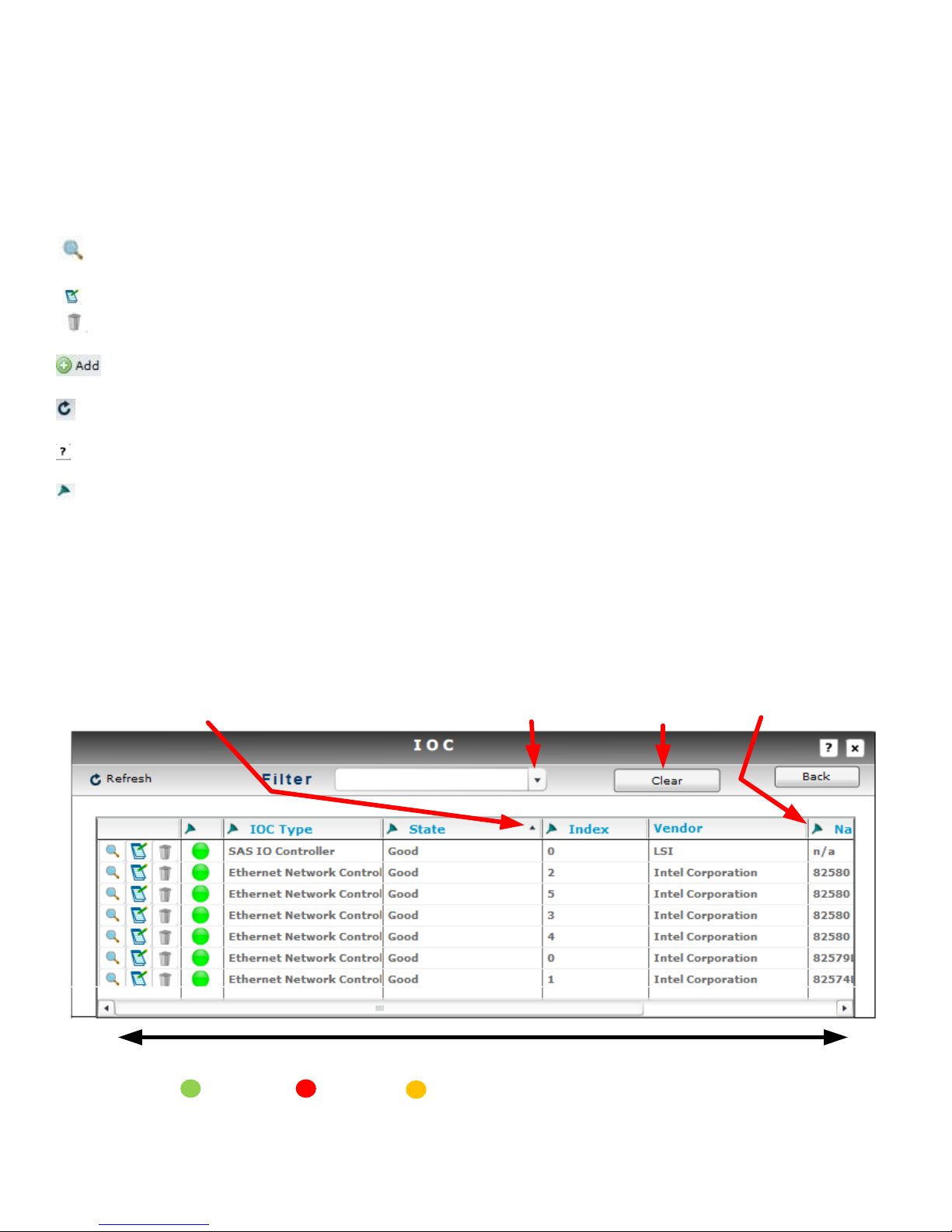
V USER INTERFACE ORIENTATION
Moves Column Information Horizontally
Sorts - Ascending & Descending
Filter Display
Active Filter Drop Down
Filter Clear
Filter Select
Good
Error
Alert
Selection will provide information detail
The Xvault Xvos family is managed via web browser using a graphical user interface. Navigation is
by instinctive selection of objects and text field entry.
SELECTION, NAVIGATION, REORDERING
Allows the viewing and drill down of the selected item’s characteristics and information
Allows the change of configuration for previously configured item or information
Deletes the item or information in its entirety. Deletion is not recoverable.
Creates an item or information
Refreshes present screen display
Displays help information for screen
Selects the filter operand
* < - to search for a value under the specified value
* > - to search for a value over the specified value
* <= - to search for a value under or equal to the specified value
* >= - to search for a value over or equal to the specified value
* Contains - This i– a text and number search features, searches for a value containing the same string of text or
number as specified
15

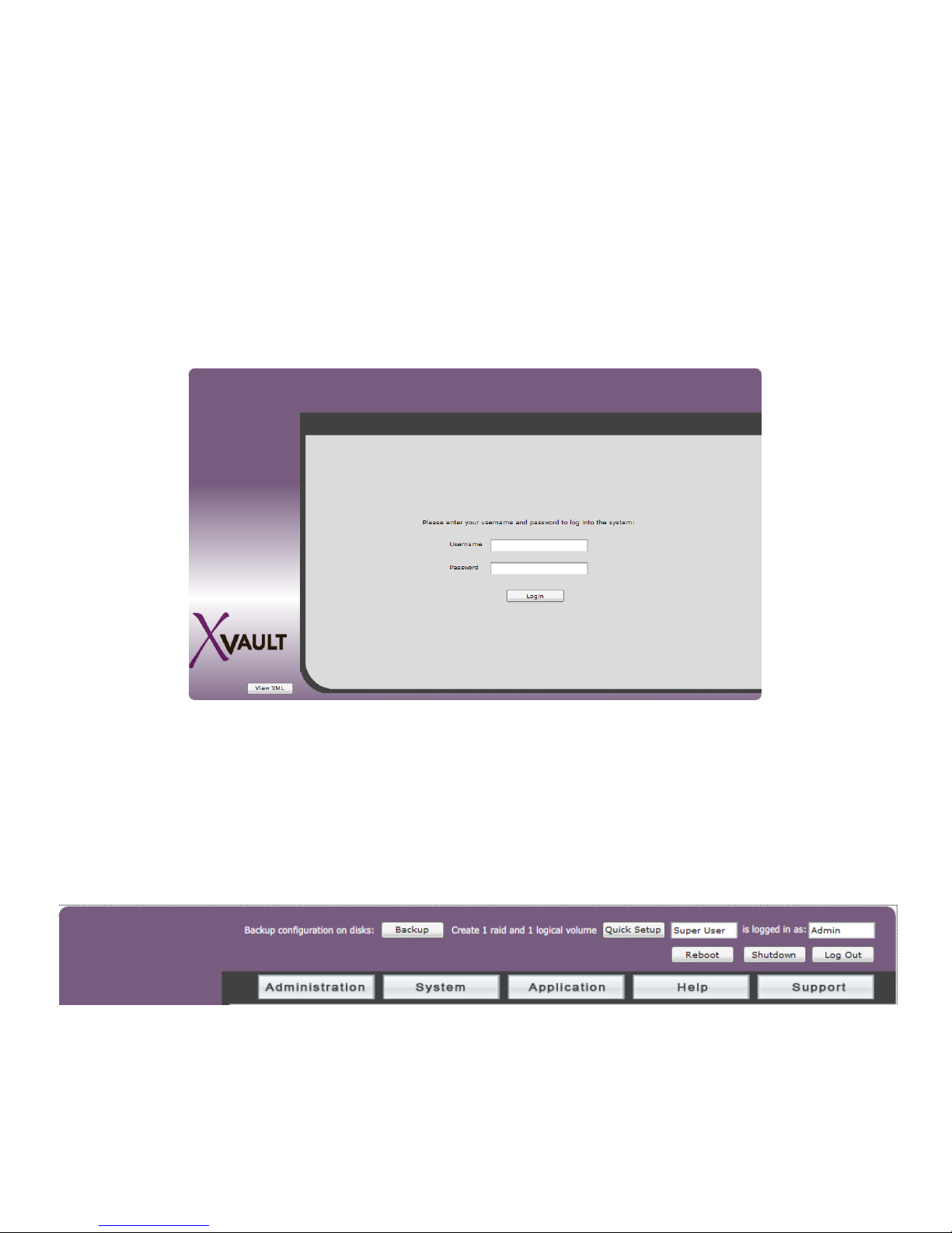
Login Screen
Administration
Install – displays license status
Setup
Controller Setup – controller name, NTP server, date and time
SMTP Setup – SMTP mail server configuration
IP Configuration – management port configuration
License Setup – license challenge and entry
User – user administration
Disks – status, member, availability and use information, smart drive enable/disable, import
external iSCSI arrays and Information
System
Host – creation, modification and status
Logical Volume – creation, modification and status
RAID – creation, modification and status
Enclosure – status, drive/RAID/Volume mapping
Application
Snapshot – creation, modification and status
Replication – creation, modification and status
Tools
System Log – system level information
IOC Tools – IO port modification and status
Diagnostics – diagnostic and tool loading
16

Help
Log Viewer – subsystem event viewer
Stats History – disk and RAID statistical information
Asset Management – cumulative asset information
Alert Management – creation and management of emails for alert notification
17

VI LICENSING
The Xvos storage appliance ships with a 30 day use license. It is limited to storage, snapshot and
replication functionality. All other advanced features if purchased are unavailable until license files
are loaded. If licenses are not loaded into the storage appliance before the 30 day expiration the unit
will not function. Data will remain intact but not accessible.
ACQUIRING “HARDWARE CHALLENGE”
Login into storage appliance as described in chapter LOCATION & ADDRESSING, selection FIRST
TIME ACCESSING THE MANAGEMENT GUI.
Select “Administration”, “Setup” then “License Setup”.
Select “Hardware Challenge”
18

The appliance will return a lengthy string that is generated based on information derived from the
motherboard and CPU. Cut and Paste this information into the email along with the Seneca serial
number and the software license number.
REQUIRED INFORMATION FOR LICENSE FILE GENERATION
1) Seneca serial number located on top front corner.
2) Software license number located immediately below the Seneca serial number.
3) Hardware Challenge text string
4) End user company name.
Different license text files based on configuration and options will be emailed back from the license
manager. Each of these licenses must be accessible from the PC accessing the storage appliance
GUI.
License Registration Email Address: Storage_License@senecadata.com
NOTE: Before entering License Text File, all RAID sets must be “Stopped”. Stopping RAID
sets will suspend Volume export and interrupt connections with all servers. It is highly
recommended that all data transfers with hosts be suspended until license(s) are entered and the
RAID Set(s) are restarted. The time to stop RAID set, enter license and restart RAID sets is less than
one minute.
ENTERING LICENSE TEXT FILES
From the License Setup screen, select “Update License Information”
19

The browser will prompt for location and name of file. Select text file and click on “Open”
Appliance will indicate successful loading of license.
Continue above sequence until all license txt files are entered and then exit license setup area.
ALWAYS backup configuration after any changes to configuration.
WARNING
When compute module and/or CPU are replaced, a new license must be reentered.
Customer care technical support can reissue a new license after software serial
number and new hardware challenge are supplied. Consult License chapter for more
information.
20

VII THE PROCESS
Create and
Modify
“The Plan”
Configure
Ports
Create Hosts
Create Logical
Volumes
Connect
Volumes at
Hosts
Create File
System,
Format &
Mount
Volumes
Backup New
Configuration
Create RAID
Sets
First time process
Creating of new RAID set and Volume
Creation of new Volume
Creation of new Host and Volume
Creation of new Host, RAID set and Volume
Creation of new Snapshot
Creation of new Replication
only if snapshot mounted
only if volume is mounted for restore
CREATE and MODIFY “THE PLAN”
Because the Xvos family covers such a broad base of host connectivity options coupled with multi
port attributes, multi RAID set support as well has different logical drive mapping it is a best practice
to create a plan or map for the Xvault Xvos. This mapping would start with the initial installation and
cover expansion and reconfigurations.
Items that can be relevant are;
Host (Servers) IP Addresses Bandwidth requirements Host network connections
Host SAS connections Network Topology Jumbo frames disposition
Storage protocols used RAID sets Logical volumes
Xvos host ports Snapshots Replication services
Thin Provisioning Data Encryption Deduplication
NAS client backup Backup To Cloud SSD caching appraisal
CONFIGURE PORTS
“Configure Ports” covers the initial management port, iSCSI/NAS/FCoE ports and SAS port
configuration to the installed environment. This is covered in the Location and Addresses
chapter of this manual.
21

CREATE HOSTS
“Create Hosts” has nothing to do with physical host servers. A “host” in this section refers to a
connection point for logical volumes so that they can be routed by protocol with or without protection.
A logical volume for example would have already have been created and Ethernet ports selected for
IO. But it is the host assignment that determines what protocol the volume will be and what the
CHAP username and password will be.
A different logical volume could have selected a particular SAS port but it is the host assignment that
determines what WWN the logical volume will communicate.
Hosts can be created and deleted during the lifecycle of the storage appliance. Volume to host
mapping can also change during the product life.
The creation and control is covered in the Create Hosts chapter of this manual.
CREATE RAID SETS
The creation, deletion and management of RAID sets actually follows host management because
connectivity and protocol planning precedes the creation of RAID sets. Seneca Data prebuilds RAID
sets based on customer input at order time and to enable production testing and burn in.
During the useful appliance life it is highly probable that new RAID sets and changes to previous
RAID sets will be introduced. The RAID MANAGEMENT chapter will provide information for the
creation and management of RAID sets.
CREATE LOGICAL VOLUMES
Logical Volumes are created from some of a RAID set, all of a RAID set or across two or more RAID
sets. The logical volume is then mapped to specific IO port(s) and host(s). The creation and
management of logical volumes is covered in the LOGICAL VOLUMES chapter of this manual.
BACKUP NEW CONFIGURATION
The Xvault Xvos backs up configuration information in the array and the OS load device. There is
also the ability to preserve custom OS image for restoration on and external USB Flash Drive. The
use of the backup capability is covered under the FEATURES chapter.
CONNECT VOLUMES AT HOST
This step does not refer to the appliance logical volume to host operation. It refers to necessary
action at an OS level in the “Host” Server. As an example an iSCSI Initiator in the host OS is
necessary to present an iSCSI volume to the disk manager so that it can have a file system created
and mounted. This manual presents limited instruction. It is the responsible of the system manager
or storage manager to have the working knowledge to present storage, create a file system and
22

mount the storage to a system. Some guidance is provided in this manual in the VOLUME
MOUNTING chapter.
CREATE FILE SYSTEM, FORMAT & MOUNT VOLUMES
This is the responsibility of the system manager or storage manager. This manual does provide
limited guidance for this process in the VOLUME MANAGEMENT chapter.
23

VIII LOCATION & ADDRESING
Drive Enclosure Slots and Trays
All DRIVES are installed beginning with SLOT 1 and continuing sequentially until all drive bays are
filled. Drives installed from the factory will be in groups of performance characteristic.. Meaning,
Solid State Drives will be installed first, followed by 15k RPM drives, followed by 10k RPM drives then
7200 RPM drives. Future addition of drives does not require reordering drives; it is advised that
additional drives be added in order of performance. SSD and 7200 RPM drives are available with
SAS or SATA interfaces, never mix SAS and SATA drives in the same RAID set or group.
Version I
3U
4U
Rear Solid State Caching Drive Location
24

Version 2
3U
4U
i. DRIVE TRAY IDENTIFICATION
All drive trays shipped from the factory will have a slot number ID affixed to the top front
25

ii. REMOVING DRIVE TRAY
Press “Lever Release Button”. The tray “Extraction/Insertion Lever” will pop out on the right side.
Gently rotate the lever outward and at the same time cradle the drive tray underneath with your free
hand. When the drive lever is fully extended, slide the drive tray out of the enclosure.
iii. INSERTING DRIVE TRAY
Match tray number to enclosure slot number. With the lever fully extended, slowly slide the tray into
the slot until lever engages enclosure. Gently push drive lever in, the tray should slide into the
enclosure without significant force on the lever or tray. Push lever in until the lever release button
locks, there should be a distinct “click” when this happens. If the lever does not move in at
corresponding rate as the tray slides into the enclosure, STOP! Pull the tray back out and try again.
When the tray is correctly installed it should be flush with all other trays in the enclosure.
NEVER move the tray in fast or force the lever to close. Damage will occur to the tray and possibly to
the drive connector.
CABLING
The Xvos servers come in two form factors but all use common components and cabling points.
There are only four main cabling points;
Power
Management
Host (Target)
Storage Expansion (Initiator)
POWER CORDS
All X-Vault storage appliances come with redundant hot swap power supplies. Each power supply
requires its own power cord. The power cords supplied are standard 115VAC machine cords. Care
should be taken to always route AC power cords away from cables that transmit data.
It is also recommended that each power cord have a separate electrical path back to the facility
service entrance. Meaning each power cord should be connected to separate circuit breakers. It is
also prudent to have at least one of the power cords connected to an uninterruptable power source.
26
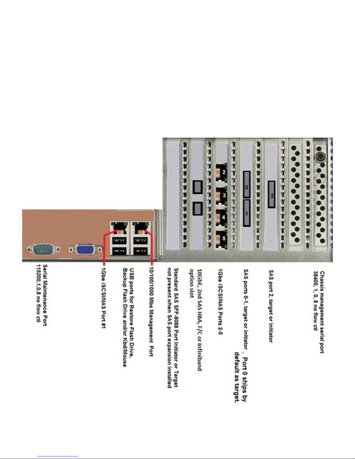
REAR SIGNAL CABLE LOCATIONS
DO NOT USE THE VGA CONNECTOR
The port is for engineering purposes only.
Power up to ready through the management port is about 3.5 minutes
Version 1
27
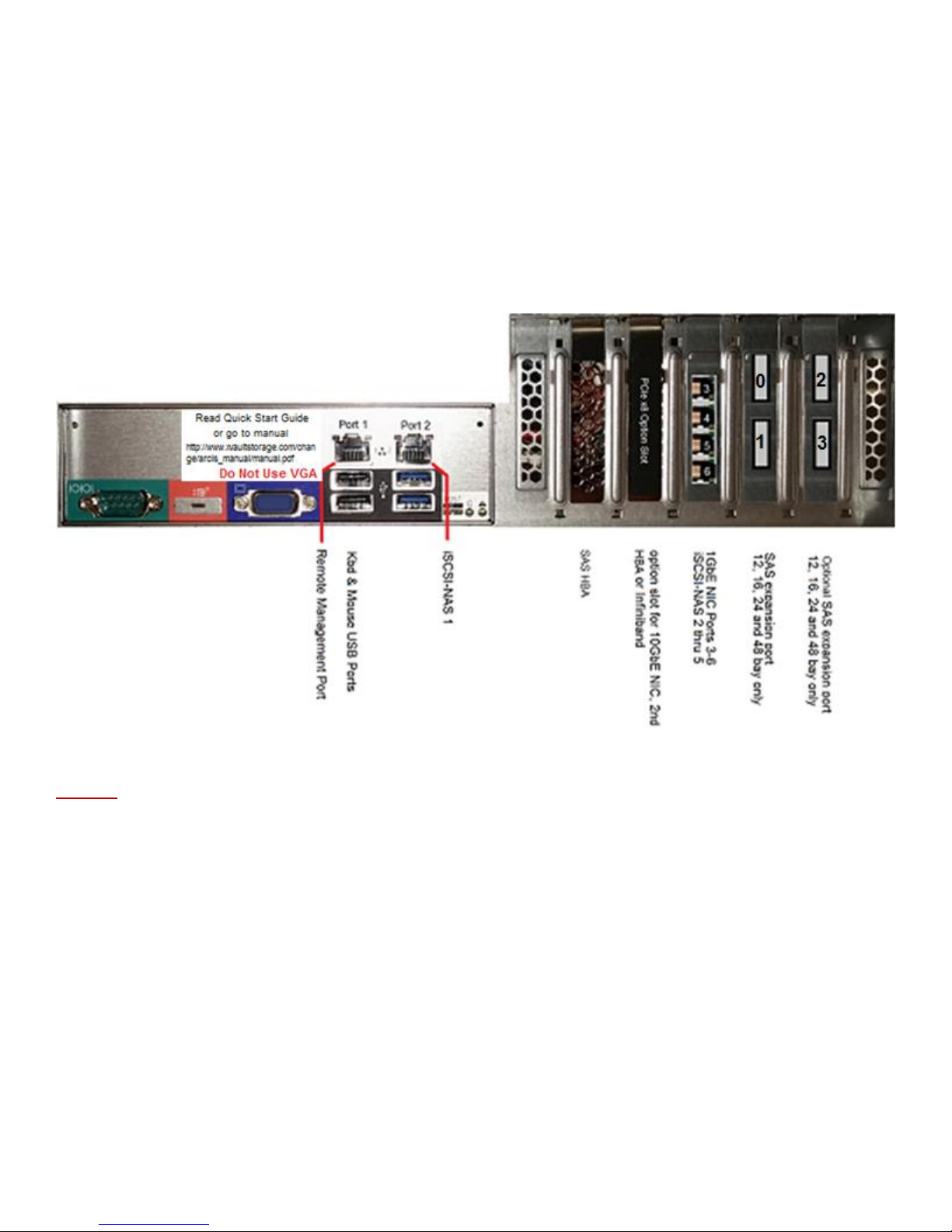
DO NOT USE THE VGA CONNECTOR
The port is for engineering purposes only.
Power up to ready through the management port is about 3.5 minutes
Version 2
VGA, KEYBOARD & MOUSE CONNECTIONS
Do Not use the VGA port or USB Keyboards and mice with this unit. The XVOS is managed strictly
and solely through the 10/100/1000 management port using IE, Firefox or Chrome browser. Java
must be installed on the managing PC.
PRESET IP ADDRESS and PASSWORD
The default IP address and mask is;
172.16.6.14 / 255.255.255.0
The default username name and password is;
Username: administrator (case sensitive) Password: P@ssw0rd (case sensitive)
28
FIRST TIME ACCESSING THE MANAGEMENT GUI
First time access should be made to configure the management port to the management LAN for the
install site. This can be done by direct connecting a laptop, desktop or server directly to the
management on the storage appliance. If the connecting device is polarity sensitive then a crossover
cable or an intermediary switch will have to be used.
Change the connecting PC’s connected port to a static subnet address of 172.16.6.x. The x can be
any value except 14. The subnet mask should be set to 255.255.255.0.
Open the PC’s web browser and in the URL field enter 172.16.6.14 and hit enter. The screen will
then display the Xvault sign in screen.
Enter username “administrator” and password “P@ssw0rd”, hit “Login” the characters are case
sensitive.
Select “Administration”
29

Select “Setup”
Select “IP Setup”
Select the icon to enter into management IP address configuration.
30

1Gbe
Ports
IP Address
Mask
1Gbe
Ports
IP Address
Mask
1
10.0.10.30
255.255.255.0
4 10.0.10.33
255.255.255.0
2
10.0.10.31
255.255.255.0
5 10.0.10.34
255.255.255.0
3
10.0.10.32
255.255.255.0
10Gbe
Ports
IP
Address
Mask
1
10.10.10.3
255.255.255.0
2
10.10.10.4
255.255.255.0
iSCSI / NAS PORT CONFIGURATION
The standard configuration of the Xvault Xvos appliances is with the first network port on the
mainboard and four 1Gbe ports on an PCIe network adapter. Cabling for 1Gbe ports to the IP SAN
should start with Port #1 and ascend. Cabling for 1Gbe ports to the NAS should follow the IP SAN
/FCoE 10Gbe ports for IP SAN should precede ports for FCoE.
As a general rule, client accessed NAS subsystems would have their IP Addresses set by the DHCP
server and the IP SAN IP Addresses will be static.
Always consult with the site network administrator before configuring storage network ports.
Storage Port Factory Presets
31

To change storage port IP address settings click on Applications
Select Tools and then IOC Tools
Select on the line of the network interface port to be changed.
Select again to gain access to next port editing screen
Select Maximum transmission unit drop down and select appropriate Jumbo Frames size.
Select Edit IP Config
32

It is highly recommended that IP SAN and FCoE SAN implementations use a non routed IP Address
and have the SAN ports segmented away from all other networks,
Click on OK then OK then Back after port information entered.
Configure each network port then exit out of IOC Tools.
33

SAS PORT CONFIGURATION
SAS ports can be configured as a “Target” or “Initiator” port. “Target” ports connect to hosts (Servers)
and “Initiator” ports connect to storage devices – Caching, SSD and Spinning Drives
Target Ports start at rear connector 0 and ascend to higher ports.
Standard Configuration - Rear connector #0
Initiator ports start with the highest port connector number and descend
Standard Configuration – Internal connector #3
External connector #1 and #2
Standard Configuration
The standard Xvos has sixteen ports. One internal x4 SAS SFF-8087 port. This is port connector #3.
There are three external x4 SAS SFF-8088 ports. These port connectors are #2, #1 and #0.
Enter the IOC Tools screen as described in the above section, SAS PORT CONFIGURATION
Select the SAS IO Controller to configure
SAS ports are divided into groups of four as are the physical connectors. All ports come in a group of
four affiliated with a single connector. The only change necessary in the field is to select whether the
ports/connection functions as a “Target” or “Initiator”.
Modification of a port/connection function requires two operations at the same time. On the desired
port check box and then use the drop down Mode to select Target or Initiator. Do not select the
dual mode Target/Initiator. A port grouping is one or the other for the storage appliance.
NOTE: For documentation and support reasons please subscribe to the Ascending Target and
Descending Initiator port number scheme.
34

IX HOST PORT MANAGEMENT
Create a “Host within the confines of the Xvos storage appliance has nothing to do with physical host
servers. A “HOST” is the connection point for a logical volume so that the volume can be routed by
protocol with or without protection.
HOST EXAMPLE:
An iSCSI logical volume would have already have been created and Ethernet ports selected for IO.
But it is the host assignment that determines what protocol link the volume will be and what the CHAP
username and password will be as well as whether mapping and masking are applied.
FINDING A WINDOWS SERVER IQN
If the IQN number of the host is not available by browsing. Login into the Windows server host you
wish to connect. Open the “iSCSI Initiator” which can be found under the Administrative Tools and
click on the “Configuration” tab. The IQN number will be displayed.
35

FINDING THE vSphere ESXi 5.0 HOST IQN
From vSphere console select the host system.
THREE DIFFERENT METHODS TO CONNECT TO AN iSCSI SERVER
The Xvos offers three different ways to connect to an iSCSI server.
METHOD I
Strictly CHAP. CHAP is an acronym for Challenge-Handshake Authentication Protocol. The protocol
supports a username and password requirement for a connection to take place. It is not a secure
transmission protocol. A CHAP only connection means that when a server uses the iSCSI Initiator to
connect to an iSCSI volume a username and password must be entered to qualify and connect. A
CHAP only presentation of a logical volume means ALL servers on the IP SAN can see the volume.
The only protection or means to keep other servers from mounting a volume is the inability to enter a
correct username and password for the volume.
METHOD II
Mapping and Masking. Mapping and masking allows the creation of a “Host” that is mapped to a
specific Server/Client IQN number. Additionally the volume is masked from being visible to any other
Servers/Clients on the IP SAN. Multiple “Hosts” may be created and a local volume can be tied to
multiple “Hosts”. This will accommodate server clustering, motion and other applications where multi
node access to a single volume is required.
METHOD III
Mapping, Mapping and CHAP. Method III brings the benefits of CHAP password protection and the
control of Mapping/Masking.
NOTE: All volumes to the same Server/Client cannot mix Method I – CHAP, Method II –
Mapping/Masking and Method III – CHAP/Mapping/Masking. A single XVOS relationship to a single
server/client must be via only one “Host” connection method.
36

CREATING A CHAP iSCSI HOST
Select “SYSTEM” from the login screen, then “Host”, then “Add”
Select “Network”, enter a “Username”, leave “Host field blank, enter twelve position “Password” with
confirmation. If confirmation matches the password entry the red circle will turn green. When the
circle turns green click “OK” and the host is created.
When a volume is mapped with this iSCSI Host type the logical volume will be visible by all servers
on the IP SAN. The only way to ensure an exclusive volume/server relationship is preserved is to
create multiple hosts each with a different Name/Password. See example below.
37

21 43 65 87 4847161510
9 14131211
222120191817 282726252423 3029 3231 4645444342414039383736353433
CONSOLE
Catalyst 2948G-GE-TX
STATUS
PSI RPSU
49 50 51 52
10/100 MGT
Username = A
Password =A
Username = B
Password =B
Username = C
Password =C
Username = B
Password =B
Username = A
Password =A
Username = C
Password =C
Because there is a username and password for iSCSI, CHAP authentication is required in the server
iSCSI initiator when connecting to the iSCSI volume.
CREATING A MAPPED AND MASKED iSCSI HOST
Select “SYSTEM” from the login screen, then “Host”, then “Add”
Enter Server/Client IQN number. See section on retrieving IQN. If your operating system is not
covered then consult OS manual or OS support service. Leave Username, Password and Confirm
Password fields blank.
38

CREATING A MAPPED/MASKED HOST WITH CHAP
Select “SYSTEM” from the login screen, then “Host”, then “Add”
Enter Server/Client IQN number. See section on retrieving IQN. If your operating system is not
covered then consult OS manual or OS support service.
CREATING A NAS HOST
The exact method used to create a CHAP iSCSI HOST is used for creating a NAS HOST – EXCEPT
the Host field is left blank. The difference will be made in the logical volume creation process.
CREATING A SAS HOST
A SAS host will automatically be created when a SAS host is connected. If it does not
then the SAS controller must be looked at under Application – Tools – IOC Tools.
39

X RAID MANAGEMENT
The intent of this section is to provide guidance in the creation and management of RAID sets within
the Xvos storage appliance.
CREATING A RAID SET
Log in to Xvos storage appliance and select “System”, then “RAID”, then “Add”
Enter a RAID Name that is relevant to the storage set. i.e. 15k RAID, SQL RAID,
Select a Quality of Service level. Multiple RAID sets of the same drive type can have different
priorities assigned. Two identical RAID sets can have a lower priority for an archiving use and a
different priority for general IT use. If all RAID sets are set at the same priority then performance is
differentiated by drive type, RAID type and number of drives in a RAID. The default is Mission
Critical.
The Level setting is the type of RAID set. The Xvos supports RAID0, 1, 10, 5 and 6. While there is
no selection for RAID10, a selection of RAID1 and using more than two drives will result in a RAID10
implementation with performance that corresponds with RAID10. RAID50 and RAID60 are not
implemented at this level. RAID50 and RAID60 performance and failed drive restore times are
achieved by spanning a logical volume across two RAID sets. This is covered in the Logical Volume
Management chapter of the manual
Write Caching sets the type of write cache to be used. Write Through performs no buffering of
incoming data this is the safe setting if no uninterruptable power is available for the storage
appliance. Write performance is severely degraded in this mode of operation. Write Cache setting
enable the write back cache capability. All writes are buffered and written to the disk array as the
array is ready. Write Caching is the default setting. Mirrored Writes is a setting reserved for HA
configurations and should not be used with the Xvos single controller models.
Read Ahead turns the Read Ahead cache On or Off. The Xvos support a self tuning read ahead
caching feature, for most configuration it is recommended that the Read Ahead be On. The default is
40

On. Turning off Read Ahead will result in cache holding data read previously on a FIFO basis – but
no read ahead.
Controller. The Xvault Xvos can support multiple SAS interfaces.
The Fast RAID selection, when checked will not allow the use of the RAID set space for creation of
logical volumes until the RAID set has been built. If the Fast RAID is not checked, logical volumes
can be built, hosts applied and IO can be done. The RAID set creation runs in the background and
will take longer to finish than if Fast RAID is checked. The default is unchecked.
The RAID drive selection screen allows for all or individual drives to be part of a RAID set. This
selection capability enables the ability to create different RAID sets with different tiers of performance
based on interface (protocol), spindle speed or solid state vs spinning.
The Choose Disks field reflects all filters that were enabled in this screen.
Individual drives are selected by the check box in the first column, if all drives are to be part of a
single drive set there is a convenient Select All box.
The Xvos does not support more than 32 drives in a single RAID set. Optimal performance is
obtained with 12 to 18 drives in a RAID set. A 32 drive limit is not a limit on presented logical volume
capacity. Logical Volumes can span across multiple RAID sets
41

Selected
Disks
Spare
Drives
Size of
Drives
RAID
Type
Usable
Capacity
5 0 1TB 5 4TB
5 1 1TB 5 3TB
16 0 1TB 5 15TB
16 1 1TB 5 14TB
16 0 1TB 6 14TB
16 1 1TB 6 13TB
Select Expert to change the RAID chunk (stripe) size. The default is 4k. 4k is an optimal setting for
SSD’s and new 4k sector disk drives. Drives with a traditional 512 byte sector should be changed to
a chunk size of 64k for best performance. It is advised to set to Expert to ensure review of the chunk
size.
Selected disks field provides confirmation of how many drives were selected from previous screen
and as a reference if selecting Spares.
Spares selection allows one or more dedicated spare drives to the RAID set being built. The number
entered effects the usable capacity available for the RAID set.
Sample Chart
RAID1 (10) Formula: ((#Drives x Drive Capacity)/2) - 1 x Drive Capacity – (#spares x Drive Capacity) – usable capacity
RAID5 Formula: (#Drives x Drive Capacity) – 1 x Drive Capacity – (#Spares x Drive Capacity) = usable capacity
RAID6 Formula: (#Drives x Drive Capacity) – 2 x Drive Capacity – (#Spares x Drive Capacity) = usable capacity
Automatic Rebuild enables the automatic rebuild of a RAID set when a failed drive is replaced. If
this box is not checked and a replacement for a failed RAID set is inserted into the appliance, a
42
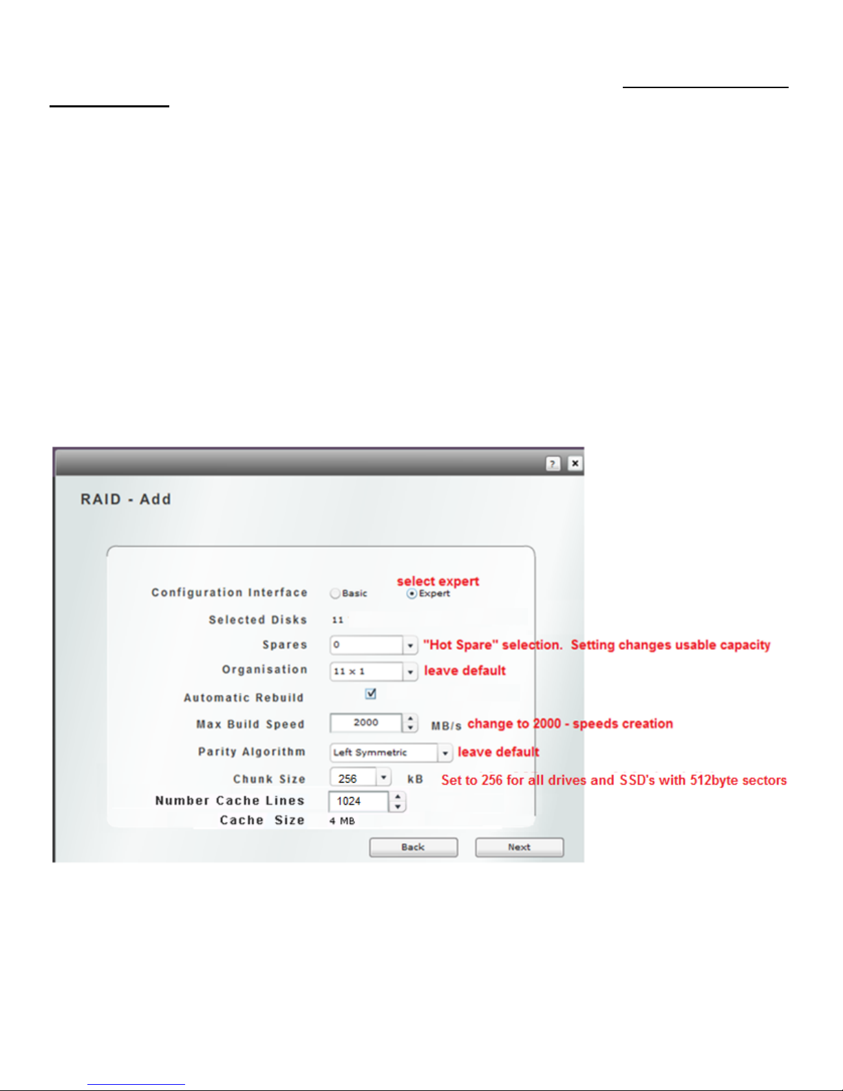
rebuild will not begin and the RAID set will continue to run in degraded mode. It is recommended to
check this box.
This storage appliance is capable of creating a RAID set at speeds up to 2000MB/s. If this is a first
time build or the subsystem is not being used and a new RAID set is being used, then it would be
advised to set the Max Build Speed to 2000. If a new RAID set is being added while normal
operations are underway a build speed of higher than 600MB/s will negatively impact IO.
The default setting for Parity Algorithm is “Left Symmetric” changing this value will have little impact
on performance. It is advised to leave at default.
Chunk Size is only viewable in Expert mode. The default is 4k. 4k is an optimal setting for SSD’s
and new 4k sector disk drives. Drives with a traditional 512 byte sector should be changed to a
chunk size of 64k for best performance.
Number Cache Lines is only viewable in Expert mode. This option allows the cache read ahead for
for chunk sizes. The default is 1024 and is the recommended setting for general IT operations. .
This value can be changed after a RAID set is built.
After clicking Next from above, a confirmation screen appears. If it is correct click Create RAID to
start RAID set build or Back to change settings.
43
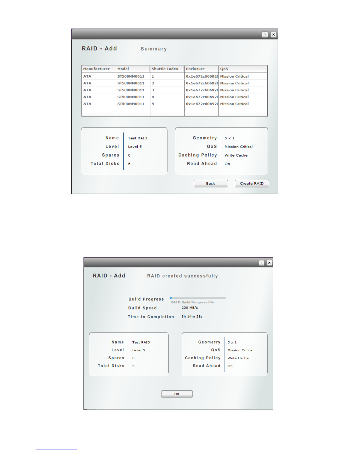
A build screen will appear immediately after the Create RAID button is selected. The RAID build
status is displayed in percentage with Build speed and estimated time to complete as well. If the Fast
Build was not checked, the creation of a Logical Volume and assignment of “Host” can ensue. If the
Fast Build was checked the RAID set build must complete before other configuration changes can be
made. The RAID set build time is better under any circumstance if the Fast Build is checked.
44

MODIFY RAID SET
To modify a RAID ser or start a manual rebuild; from the login screen select “System”, then “RAID”.
Click on the Edit icon on the line of the RAID set to modify.
RAID set modification is limited and requires stopping the RAID set. WARNING: Stopping the RAID
set will suspend all disk access this can also not be done without first stopping all Logical volumes
that use part or all of a RAID set. This can result in corrupted data if the server using the logical
volume associated with the selected RAID set is not dismounted first.
The only changeable values of the RAID set is the RAID Name. The Home Controller should only
be modified in the Xvos HA model, this value should not be changed.
If a RAID set has a bad disk member (degraded mode) and the bad disk has been replaced, a
manual rebuild can be started by clicking on the Rebuild box.
45

VIEWING RAID INFORMATION
To view RAID ser information; from the login screen select “System”, then “RAID”. Click on the
View icon on the line of the RAID set to modify.
The RAID set details are displayed in the format below. Clicking on the View Disks icon will drill
down on the drives that are members of the set. Clicking on the View Logical Volumes icon will
display all Logical Volumes that are fully or partially contained in the selected RAID set.
46

CREATING A GLOBAL SPARE
Creating a “Global Spare” is completely independent from the RAID set creation process. A global
spare is selected under the Administration – Disks section.
A “Global Spare” works an automatic rebuild disk in the event of a RAID member failing. The only
difference between a global spare and a dedicated spare is a global spare drive will be available
across multiple same drive size and class RAID sets.
The XSos software determines if a global spare drive is appropriate for use as a spare for a RAID set.
Meaning; 1) It must be the same interface type as the other drives in a RAID set. 2) It must be the
same size or slightly larger as the drives in a RAID set. When the two requirements are met, the
global spare is eligible and will function as a global spare for one or more RAID sets.
Note: One or more “Global Spares” may be designated. As a global spare is used it is no longer
available for other RAID set drive failure replacement.
From the Login screen select “Administration”, then “Disks”. Using the right-left scroll bar, identify a
“Free” disk to select as a “Global Spare”. When the drive to use has been determined, click on the
notepad icon adjacent to the drive.
From the “RAID role” drop down, select “Global Spare” then “Ok”. The global spare has been
selected.
47

XI VOLUME MANAGEMENT
This chapter provides guidance for the creation, modification, viewing and attachment to host servers.
Logical Volumes can be created using part of a RAID set, all of a RAID set or portions of multiple
RAID sets. Volumes are assignable to one or more IO Ports. IO ports can be 1Gbe or 10Gbe
Ethernet, Fiber Channel, Infiniband or SAS. Volumes also have protocols associated with them at
creation. The protocols can be modified later.
A logical volume may also be expanded after creation. The expansion process does require the
volume be stopped for a few moments. This is considered a disruptive process; however an
Operating System would require dismount and remount to use the expanded capacity. So a
coordination of OS disk dismount and expansion will minimize device usage impact. Expansion of a
volume does not impact other volumes on the storage appliance. If volume expansion without any
system disruption is required then the Thin Provisioning option should be used. Thin Provisioning is
not a standard feature, to check if your system is licensed for the option check under the
Administration – Install screen.
PREPARATION FOR LOGICAL VOLUME CREATION:
A) Make a list. What the names of the Logical Volumes?
B) When creating Logical Volumes consider and write down the following values and information;
i Will the Logical Volume have snapshots taken?
ii How Often and what is the initial and expanded size buffer space and snapshots?
iii What RAID set will the buffers and snapshots be stored?
iv Will this volume be a remote replication “destination” (target)? If so it must be at least 1GB
larger than the “source” volume.
The snapshot & buffer capacity plus the sum of all files and folders on the RAID set must be less than
the available capacity of the RAID set where the snapshots/buffers will reside.
EXAMPLE: Snapshots taken of LVa
Snapshots reside on RAID Set “8TB SATA”.
Next snap buffer space .8TB
Snapshot LVa #1 . 4TB
Snapshot LVa #2 .4TB
Total Snap Space Required 1.6TB
RAID set “16TB SATA” 8.0TB
Space used in RAID set “16TB SATA” -6.6TB
Total snap space -1.6TB
-0.2TB Snap space will not fit
Corrections: 1) Move snapshots and buffers to a different RAID set. 2) Reduce frequency of
snapshots. 3) Reduce retention time for snapshots. 4) Add or expand a RAID set.
48
CREATING A VOLUME.
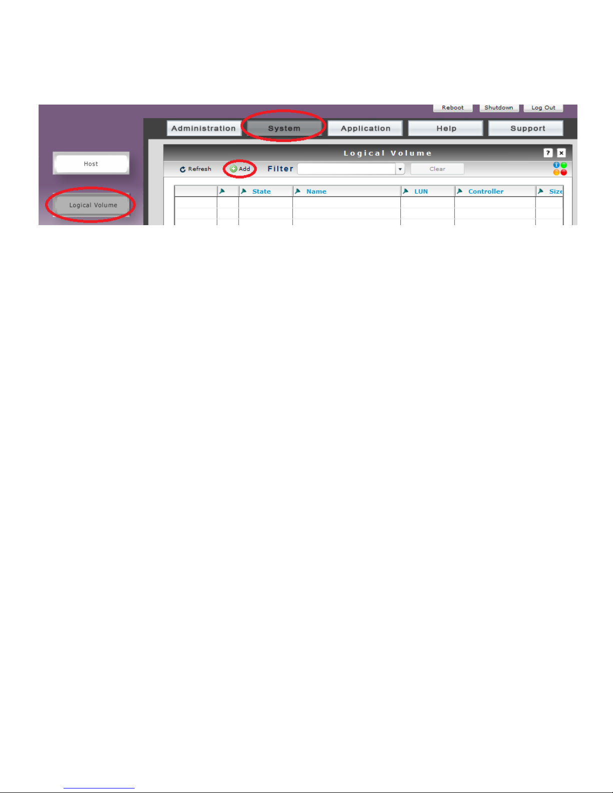
From Log In screen, select “System”, then “Logical Volume” and then “Add”
Logical Name of the volume should be relevant to the use of the volume. Reference the servers(s)
or storage use or capacity or performance tier – Server A, Document Storage, 18TB Volume, 15K
SAS Volume.
Size (GB) is entered in gigabytes, this size is not limited to a single RAID set. In the next screen you
can select what capacity points resides in what RAID set. The distribution of capacity across RAID
sets is how RAID50 and 60 performance and shorter member rebuilds are accomplished.
The LUN setting is settable or forcible but the LUN value auto increments with each volume creation
so it is not necessary to enter a value here.
Enable Thin Provisioning will be covered in the section for Thin Provisioned volume creation.
QoS Required set the volumes priority over other volumes. This is a IO processing priority and is not
a substitute for hard storage tiering as in SSD, 15K SAS, 10K SAS, 7200 RPM SAS, 7200 RPM
SATA-III. Faster RAID components create faster IO and transfer rates. QoS at a volume level only
provide preferential IO on same hardware tier volumes. Mission Critical is the default setting.
Safe Writes option guarantees the data was sent to disk before responding a write operation is
complete. This does not stop write back caching, it only waits until the data has left the cache. The
default is Off. Turning this option will slow the write operations because of the acknowledgement
latency.
The Enable Throttling option allows the volume to slowed for specific purpose. As an example, this
appliance was used at a remote office for the local servers and served as a remote disaster recovery
site. Enabling throttling on the disaster recovery volume would not impact the remote sites transfer
because the route over a slow connection BUT the throttle would allow greater performance for local
volumes. In a local application the backup member can still function with transfer rate restricted and
allow other more mission critical storage to enjoy greater bandwidth. Throttling can be at an IO or
transfer level. It is recommended that host server IO resources be monitored to determine how thess
levels are set. The default is unchecked
49

Bandwidth Throttle limits how many bytes can be transferred in a second. This setting typically
effects applications that make long transfers like video or image records
I/O Throttle limits how many input output operations can occur in a second. This setting effects multi
user general file access and database applications.
From this screen the RAID set or sets is selected that the logical volume space will reside. If the
logical volume will reside solely in a single RAID set you will select a RAID set and proceed to the
end of the logical volume creation. If a logical volume will reside across multiple RAID sets a portion
of a RAID set will be selected and a return to the following screen will allow the selection of another
RAID set with subsequent capacity apportionment. First the logical volume created from a part or all
of a RAID set will be shown.
50

Reserved GB space is filled in by three different methods. 1) Manual entry, this entry will supersede
space allocation from a previous screen. 2) Set to remaining space in LV will insert previously
allocated space from two screens past. This is a typical button to press. 3) Set LV size to max
RAID size will override previous space allocation and use all remaining RAID set space. Examples; If
a previous logical volume used 3TB of a 16TB RAID set, then pressing the Set LV size to max RAID
will apply the remaining 13TB to the volume being configured. If the RAID set was a virgin 16TB and
without any logical volumes then pressing the Set LV size to max RAID button would apply 16TB to
the volume being configured.
NOTE: Manually entering less space than assigned previously will require selecting another RAID set
and then entering the balance capacity in subsequent selection.
51

Take note of reserved space information
52

SPANNING A LOGICAL VOLUE ACROSS RAID SETS
53

VOLUME IO PORT ASSIGNMENT.
A volume may be assigned to multiple ports and a volume can be assigned to multiple protocols. With
one exception – NAS (CIFS or NFS) cannot share ports with iSCSI or FCoE ports.
54

A volume can be connected to one or more “Hosts”. Hosts creation direction was covered in previous
chapter.
55

VOLUME CREATION REVIEW
Review configuration, click Back to change, click Create Logical Volume to finish
Logical Volume creation complete as well as being mapped
56

VIEWING A LOGICAL VOLUME
The Xvault Xvos provides the ability to view a logical volumes attributes as well as the ability to view
host assignment and RAID set(s) containing the logical volumes data.
From the login screen, select “System” then “Logical Volume” and then adjacent to the logical
volume to view.
MODIFYING A LOGICAL VOLUME
Privileged user s may modify select logical volume information.
From login screen, select “System” then “Logical Volume” and then adjacent to the logical volume
to modify.
WARNING: In order to modify parameters the logical volume must be stopped. Stopping a logical
volume will cause the volume to be unavailable for read/write operations. It is advised to dismount a
logical volume in the Server (host) operating system before stopping a logical volume.
57

To change Port Mapping or Host Mapping click on the appropriate image.
EXPANDING A LOGICAL VOLUME
From the Edit Logical Volume screen click on Edit Size.
Select adjacent to the RAID set where the logical volume expansion space will reside. As is the
case with logical volume creation, expansion space can reside across several RAID sets.
58

CREATING A THIN PROVISION VOLUME
From Log In screen, select “System”, then “Logical Volume” and then “Add”
Enter information as if you were creating a standard logical volume as covered earlier in this chapter.
EXCEPT check the “Enable Thin Provisioning”
NOTE: The value entered in “Size (GB)” will be the size of the volume reported to the operating
system. This is not necessarily the space used on the array.
Again use the same process to determine where the logical volume space will reside – part of a RAID
set, all of a RAID set or across two or more RAID sets.
59

Enter the amount of actual space the logical volume will initially consume. In this case 25GB
CAPACITY PRESENTED TO OPERATING SYSTEM: 75GB
CAPACITY USED BY VOLUME: 25GB
Confirmation of OS capacity presentation and actual capacity used
60

Enter the “Threshold” percentage of the actual capacity used to trigger an automatic expansion of
usable space for the thin volume. “Auto Allocate (GB) is the amount that will be added to the usable
space of the thin volume.
In this screen example when 22.5GB of the thin volume is used, 3GB will automatically be added.
The next Threshold trigger point will be 25.2GB. This process of usable capacity expansion will
continue until 75TB is met. At that point auto expansion will stop.
THIN PROVISIONING FAQ’s
Q. Can the “Auto Allocation” be greater than the present volume size?
A. No. The “Auto Allocate” size value can be up to the presented capacity minus the originally used
capacity. In this case; 75GB – 25GB = 50GB the maximum “Auto Allocate” value.
Q. Can the “Threshold” percentage automatically change as the volume increases the used capacity?
A. No, this is a fixed field.
Q. What Happens when the thin volume is fully expanded and all space is consumed?
A. As with a regular, the volume can be dismounted at an OS level. The volume can be stopped,
expanded, restarted and mounted to the OS.
Q. Are there alerts sent when the used capacity reaches a certain percentage of the presented size?
A. Yes
Q. If a presented value is too high initially; can the size be lowered without losing data?
A. No, this ability is referred to as “Capacity Recapture”. It is road mapped for future release.
61
CREATING SINGLE DRIVE VOLUMES
The Xvos has the capability of presenting a single drive exactly the same as a volume sourced from
RAID space. A single drive volume does not have any data protection capability, if the drive fails the
data is lost. A single drive volume cannot be thinly provisioned, cannot be expanded beyond the
drives capacity and cannot be split into multiple volumes
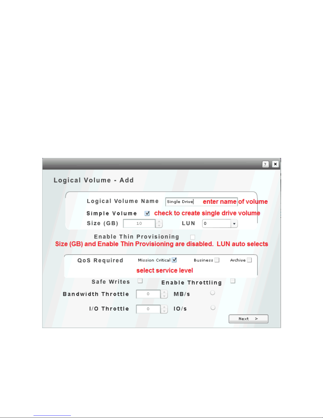
The creation of a single drive volume is exactly the same as a standard volume with the exception
that the space is not derived from RAID space. Instead the checking of “Simple Volume” will
allow/require the selection of a “free disk drive”, one that has not been assigned to a RAID set or
global spare. A “free disk drive” maybe an individual disk OR an imported external iSCSI volume
1. From the login screen select the System screen, then the Logical Volume screen. Select
Add to create a new single drive volume.
2. Enter Logical Volume Name, check Simple Volume, set QOS service level. To disable write
caching, check Safe Writes (default is unchecked). If throttled performance is desired, check
Enable Throttling default is unchecked) and then desired Bandwidth and/or IO restraints.
3. The following screen will only display unused or free disk drives. Select the desire drive to use
and select Next to proceed.
NOTE: Consider the future use of unused/free disk drives and how it may impact future RAID
sets, global space or expansion.
62

4. The remaining steps which include IO port selection and host selection are identical to the
creation of a logical volume which is outline earlier in this manual.
63

XII MOUNTING VOLUMES TO OPERATING SYSTEM
ATTACHING ISCSI VOLUME TO WINDOWS SERVER 2008
This procedure will demonstrate how to connect an iSCSI volume (virtual disk) to a Microsoft
Windows host server.
1) Logon to host server and open “iSCSI Initiator”
2) If target is auto discovered click on target. If target not discovered then click on “Discovery”
tab.
3) Click on “Discover Portal” and enter IP address(s) of the X-Vault where iSCSI volume(s) are
located. This is all Xvault Xvos network ports attached to the IP SAN.
64

4) Add ports until all Xvault Xvos IP SAN ports are added and visible in the Discovery tab.
5) After manually adding storage server iSCSI ports, return to “Targets” tab. The Xvault Xvos
IQN should now appear in the “Discovered targets” field. If not enter the lowest IP address of
the Xvos IP SAN ports into the Target field and click on Quick Connect. The status should be
65

inactive. Highlight the Xvos IQN then click on “Properties”. In properties screen click on “Add
session”
Note: If the Xvos IQN does not appear on the screen even after forcing a quick connect,
double network connections and configuration. Double check all network connections and
configurations.
6) In properties screen click on “Add session”.
7) Double check the “Target name” to make sure it matches the storage server to be attached.
Check “Add to favorites box”. Check “Enable multi-path”. Click on “Advanced”
66

SAMPLE HOST TO TARGET DESIGNATION
HOST
TARGET
10.0.10.254
10.0.10.30
10.0.10.253
10.0.10.31
10.0.10.252
10.0.10.32
10.0.10.251
10.0.10.33
10.0.10.250
10.0.10.34
8) Select “Microsoft iSCSI Initiator” from drop down. Select server iSCSI IP address. Coordinate
a first Server IP address with a first Storage IP address. Repeat until all Server iSCSI IP
addresses are matched to Storage iSCSI IP addresses. This step creates the multi path
relationship between host and target. The multi path (MPIO) relationship is critical to up time
and performance.
9) Verify each Test Server NIC is being used for MPIO by scrolling down. Disk 1 should appear
five times because five Test Server NIC ports were configured to a specific target.
67

10) Verify Server NIC port to Storage Appliance links by highlighting “Path ID” and clicking on “Details”
ENTRY POINT FOR SAS & iSCSI VOLUMES APPEARING IN DISK MANAGER
MOUNTING & FORMATING VOLUME ON SERVER/HOST
This section covers
Drive type defined,
Partition type defined
Drive letter assigned
Quick format
68

1) Click on “Start”
2) Open ”Administrative Tools”
3) Click on “Computer Management”
4) Click on “Disk Manager”
5) Select partition type MBR or GPT.
Choice Help:
a. If partition is going to be larger than 2TB than select “GPT”
b. If partition id going to be a boot partition the volume, it must be smaller than 2TB and
have a MBR partition style.
NOTE: In this example, GPT style will be selected
6) Right click on unallocated storage and select “New Simple Volume”
69

7) Click “Next” on the first screen of the “Welcome To The New Simple Volume Wizard”
8) Specify the maximum capacity on the “Specify Volume Size” screen. Remember best practice
is to create the correct number of volumes in the Storage Server to facilitate better
performance, Not to partition space in the server.
9) On “Assign Drive Letter Or Path” screen, select appropriate drive letter and click on “Next”
70

10) Select the red circled defaults. On the “Volume Label” make selection that it means
something to the host. The simple reinforcement of the actual letter. If the underlying RAID
set is special make note in the name; “Drive_E 15k” or “SQL”
11) Click on “Next” after selections are made and data entered.
12) Review selections, if correct click on “Finish”, if changes are to be made click on “Back”.
13) Procedure finished, exit “Disk Management”. The volume now appears to the server/host as a
directly connected disk drive “E”.
71

XIII SNAPSHOTS
Snapshots are recordings of changed data on an iSCSI volume. This changed data is often referred
to as a “Point In Time Recoverable”. The time span that changed data is recorded is set by schedule
or from the last time a snapshot was performed manually. A “Snapshot” only contains changed data;
it is not a copy of an entire volume.
Snapshots can be restored to the volume as a whole or granularly at a file or folder level. When
restoring a file or folder it would be considered a best practice to copy the file from the Xvos product
and pasting it to the host server where the iSCSI volume is mounted.
PREPARING TO CREATE SNAPSHOTS
1) Snapshots reside on a disk on the storage server. There must be enough free space to
accommodate all manual and scheduled snapshots on one of the drives located in the storage
appliance. Please determine space required and select suitable drive (as in formatted drive
with a letter designation) on the USS appliance.
2) The system supports a maximum of 64 snapshots per logical volume. The total number of
volumes supported is unlimited.
3) The present version of Xvos supports 255 mounted volumes. Every snapshot that is mounted
deducts one volume from the maximum of 255. Snapshots that are not mounted do not weigh
against the total volume count. If it is not desired to impact the mounted volume drive count,
DO NOT check the Auto Export button.
4) Future versions of Xvos will raise the number of mounted volumes to 512.
CREATING A SNAPSHOT
From login screen, select “Application” then “Snapshot” and finally “Add”
Retention Policy allows the time that a snapshot will be retained in a system. The selections are
Locked, Keep For and None. Locked snapshots cannot be deleted from the operating system.
Keep For allows a predetermined time for the snapshot to be stored. When Keep For is selected a
time drop down box opens to the immediate right of the Retention Policy selection box. A snapshot
72

may be kept at a minimum for 1 hour and up to 99 years. Time increments are hourly, weekly,
monthly and by years. None simply means there is no policy with regard to the snapshot created.
Buffer Size is the initial size a snapshot capacity when started. Threshold is the percentage used of
the present buffer size that will trigger the expansion of the buffer space. Reprovision Size is the
expansion capacity added to the buffer size when the threshold is met.
Windows Compatible when checked will cause the snapshot to be created in a Windows OS file
format. It will copy the source partition type, either MBR or GPT. Not being checked will create a
Linux/Unix compatible file system formatted mountable snapshot. The default is off.
Automatic Export when checked will cause the created snapshot to be associated with the source
volumes host. Using this check box will immediately reduce the number of volumes presentable by
one because it is in fact now a volume and can be viewed in the logical volumes summary screen and
be mounted by a host/server.
Repeats sets the frequency that snapshots will be taken. Settable values are once, hourly, daily,
weekly and monthly.
Select only one volume that will have a snapshot taken of changed data.
73

Selects the RAID set where the snapshot buffer space will reside. Buffer space is reset when a
snapshot is taken.
Final review of snapshot parameters. Clicking on will start the changed data recording.
74
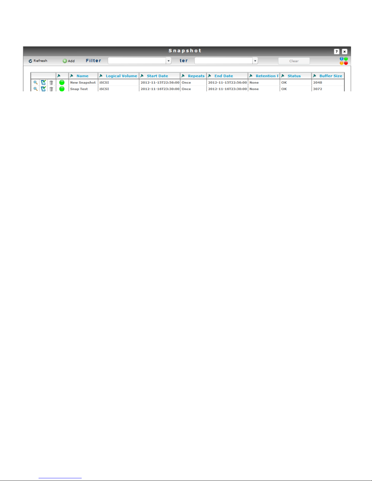
Snapshot summary screen.
75

XIX ATTACHING EXTERNAL ISCSI STORAGE APPLIANCES
The Xvos can attach iSCSI standards compliant storage appliance volumes and provision for use as
a disk drive. Seneca Data only guarantees compatibility with Xvault USP and Xvault Xvos iSCSI
volumes. If a third party iSCSI appliance or volume presented from a third party iSCSI appliance
does not work correctly, Seneca Data may, at its sole discretion, apply engineering efforts to ensure
compatibility. Engineering services to ensure Xvos compatibility may be chargeable.
An external storage appliance or volume is connected through the Disks screen found under the
Administration tab on the login screen. Once an external iSCSI storage appliance (volume) is
attached it will appear as a disk resource. This disk resource can be used as a single drive volume or
combined with other drives to create RAID sets.
An externally attached iSCSI volume only connects via a single network port. As such performance is
limited to the bandwidth of that port. It is important to recognize this as it may or may not have severe
repercussions with regard to performance.
1. From log in screen, select Administration, select Disks then select iSCSI Storage.
2. Enter an IP address from any of the ports the remote iSCSI volume is exported in the Host field.
The Port value should be 3260 unless a non standard iSCSI port is used by the remote iSCSI volume.
If the remote volume is CHAP protected, the Chap authentication must be selected along with the
correct Username and Password.
76

3. Check the correct IP address(es) and select Start Initiators to import and start external volume
4. Import volume State will change to Online and start successful start of iSCSI initiators will be
indicated.
5. Remote volume will appear in disk list and can be used as any standard hard disk.
DELETION OF REMOTE iSCSI DISKS
Remote iSCSI Volumes (local disk) are removed by using the iSCSI Tools menu located under the
Application then Tools selection.
1. Select modification icon.
77

2. Select appropriate IP address of desired remote iSCSI volume to delete, click on Stop
Initiators. System will notify of successful action,
3. The imported iSCSI volume can be restarted anytime. To permanently remove the import, always stop
the initiator first as outlined above. Then delete volume. System will prompt for final approval, if
given the import will be deleted.
NOTE: Once you delete a remote volume you cannot reimport it, all data will be lost upon reimport.
78

XX REPLICATION
VALID DESTINATIONS CONSIDERATION
Same array Xvos volume
Same array single disk
Must be connect as “Simple Volume”.
Local external Xvos array
Must be connected as external iSCSI appliance then “Simple Volume”.
Local external 3rd party iSCSI array
Must be connected as external iSCSI appliance then “Simple Volume”.
Remote external Xvos array
Must appear to be in same subnet as source, must be connected as external
iSCSI appliance then “Simple Volume”.
Remote external 3rd party iSCSI array
Must appear to be in same subnet as source, must be connected as external
iSCSI appliance then “Simple Volume”.
REMOTE destination volumes must be at least 1GB larger than the LOCAL source volume. This
allows for metadata to be written to the volume as part of the import process
Replication is the copying of one logical volume to another logical volume at a block level.
Replication is also referred to as “mirroring”. Replication starts first by synchronizing all blocks
between the source and destination. When the “synchronization” is complete only “changed” blocks
are transferred from the source to the destination. This “change only” function greatly reduces IO
between the “source” and the “destination” and preserves read performance on the source volume.
The “change only” capability allows a WAN link to be effective with a lower speed link in typical IT
environments that do 75% to 80% reads.
The Xvos 3U and 4U storage appliances support the ability to replicate one volume, “source”, to
another volume, “destination”, or to multiple volumes. The source can replicate to volumes in the
same array via SAS or to external volumes via iSCSI or FCoE protocols. External destination targets
for replication can be Xvos appliances or any iSCSI compatible device approved by Seneca Data
engineering. An external destination volume may be local or across a WAN.
Replication does impact source volume performance. The use of QoS and IO/Bandwidth throttling of
the destination volume will preserve performance of the source volume.
If a link between the Source and Destination is broken, the changed blocks will be tracked and stored
at an address level rather than a data level. Once the link is restored between the Source and the
Destination, the destination will catch up or “sync” to the source and continue to write net change.
This method saves valuable data space. This Seneca unique technology is referred to as “Zero
Space Replication”.
Destination volumes can be exported to one or more block level protocols, iSCSI, F/C, FCoE or SAS,
using 1GbE, 10GbE or fibre channel physical interconnects and mounted to systems/servers.
Possible uses for this capability include but are not limited to; remote site mounting in a capacity as
an emergency data center or local use as a “Poor Mans Storage Cluster” in the event of Source
appliance failure.
Note: Care should be taken anytime a block level volume is mounted to two or more hosts without
server clustering in place. Without server clustering in place, equal write access from more than one
server can result in data corruption.
79

“Source Volume”
“Destination Volume”
Internal “Source” to “Destination” Replication
“Source Volume”
Internal “Source” to “Destination” Replication
Master to Expansion
“Destination Volume”
KEY POINTS
Replication is done at a volume level
Destination volume must be the same or greater capacity as the Source
o A remote “destination” must be at least 1GB larger than the local “source” volume
Source and external Destination must be in same subnet – LAN or WAN
Tune the Destination volume to preserve the Source primary performance characteristics
80

CREATING A REPLICATION SET
1. Application Select, then Replication and finally Add.
2. Select Source volume and Next.
3. Select Destination volume and Next.
81

4. Assign a unique name to the replication set.
5. The replication process is started.
Monitoring Sync Process or Current Status of Replication Pair
The status of a replication may be monitored by selecting the monitor icon of a specific replication
pair.
82

STOPPING, RESTARTING and DELETING REPLICATION SETS
A replication pair can be stopped and restarted. When a replication pair is stopped the “source”
volume changed data block addresses only, no data, are stored. When the replication process is
restarted the “destination” resynchronizes in catch up mode then assumes normal synchronization of
changed data on the “source”. A Delete will clear the replication process and leave data intact on
both volumes.
STOPPING A REPLICATION SET
1. Select Application, select Replication, select modify icon of replication set to stop, Stop
Replication.
2. Replication process stop notification will appear and volume status will change to RED.
RESTARTING REPLICATION SET
1. Select Application, select Replication, select modify icon of replication set to stop, Start
Replication.
2. Replication will be restarted and indicate accordingly.
83

XVI BACKUP OF SPECIFIC CONFIGURATION SETTINGS
This procedure is used to backup specific user changes to the storage appliance settings ONLY.
These changes include user additions, array control changes and network changes. Host, RAID
array configuration and volume structure is also saved.
RAID array/Logical Volume resident data and structure must be replicated to a different Xvos
subsystem, to the cloud using option Backup To Cloud feature or backed up by hosted backup
software.
By clicking on the Backup button on the login screen, the configuration parameters are saved to the
disk array and to the internal USB Flash Drive automatically. To backup a bare metal restorable
image, select the USB flash drive installed in a rear USB connector and click on “OK”. The backup
will ensue with confirmation of successful backup to flash drive.
84
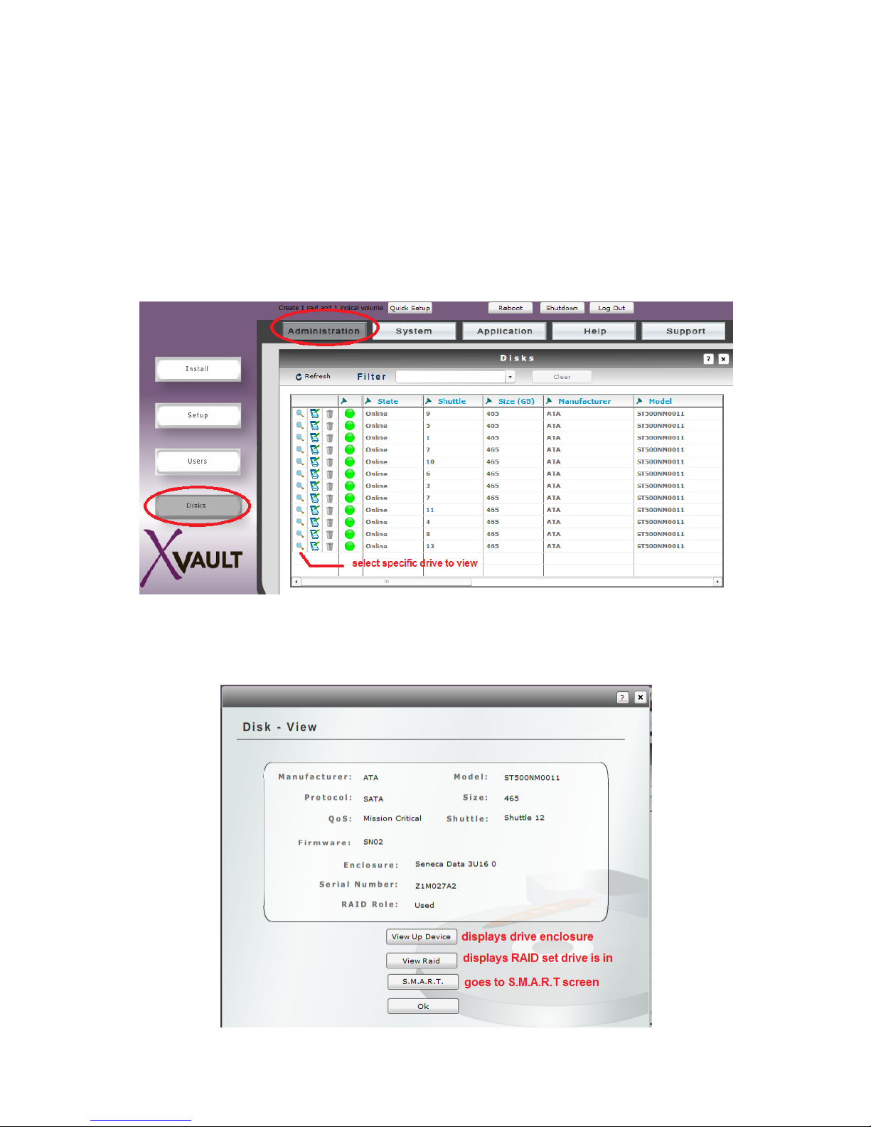
XVII INDIVIDUAL DRIVE CONFIGUATION AND S.M.A.R.T
Individual drive information may be viewed as well as S.M.A.R.T information. The ability to have
S.M.A.R.T. information reported the capability must be enabled. By default S.M.A.R.T. reporting is
disabled to enhance performance. Drive errors are always reported, not the predictive drive failure
information that S.M.A.R.T. provides when S.M.A.R.T. is disabled.
VIEWING INDIVIDUAL DRIVE INFORMATION
From login screen, select “Administration”, then “Disks” and then the individual drive for review.
85
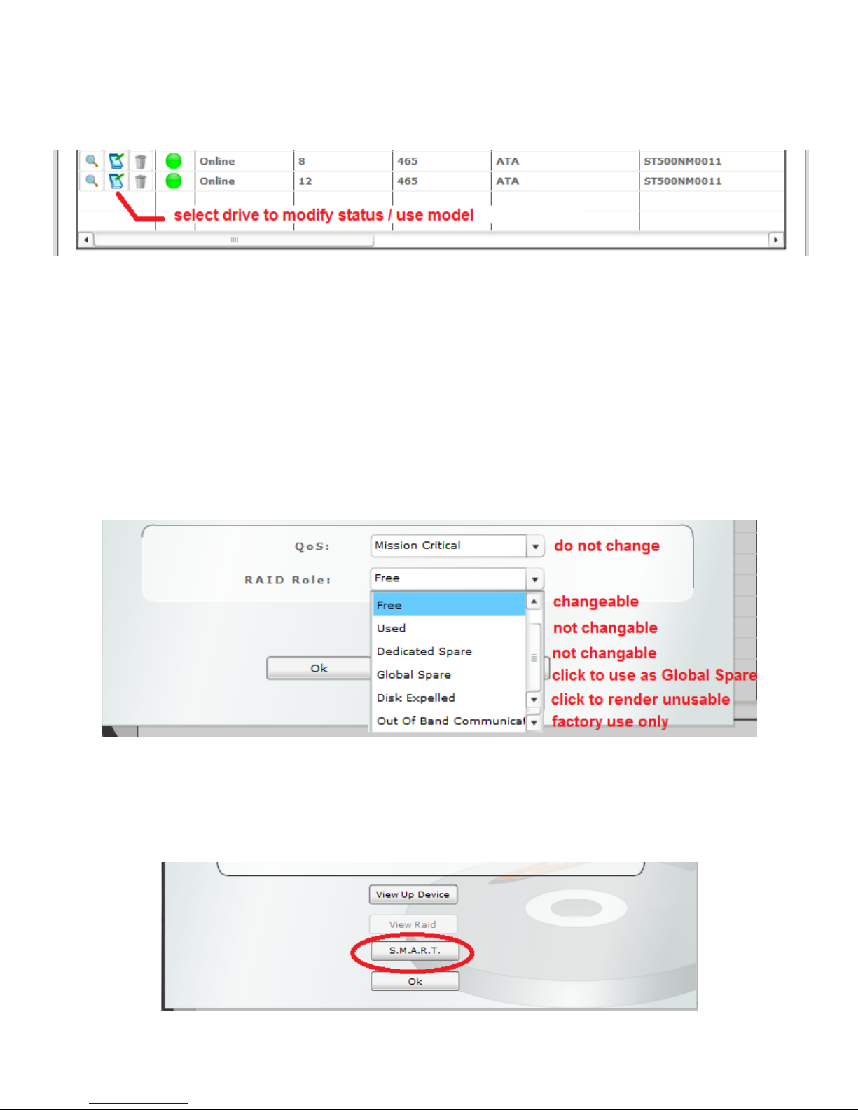
MODIFYING DISK USE / MODEL
From the Disk screen click on the notepad icon that corresponds to the drive you wish to change
“Free” indicates the drive is not used in any capacity and is available for individual function selected
below or to become a RAID member.
“Used” and “Dedicated Spare” indicates the drive is a member of or associated with a RAID set. The
drive is not available for change.
Select “Global Spare” to dedicated drive as a universal spare. See “Global Spare” section under
RAID Management for configuration information.
“Disk Expelled” will render the drive useless for any function in the array.
“Out Of Band Communication” is a factory setting, do not use.
VIEWING DRIVE S.M.A.R.T. INFORMATION
From the Disk screen select the drive using the magnifying glass icon. Select “S.M.A.R.T.”
86

The specified disk drive information will be displayed. This is current S.M.A.R.T. information. By
default S.M.A.R.T. drive information is not part of the alert notifications. If S.M.A.R.T. status
notification is desired, the capability must be enabled. WARNING: Enabling S.MA.R.T. does impact
performance. Disable S.M.A.R.T. does not prevent SATA disk drives from reporting errors only
reporting predictive analysis information is not transmitted.
NOTE: ONLY SATA interface drives have S.M.A.R.T. information
ENABLING & DISABLING S.M.A.R.T
From the Disk screen select the drive using the magnifying glass icon. Select “S.M.A.R.T.”
87

XVIII HOUSEKEEPING
SETTING SYSTEM NAME, DATE, TIME & NTP
From the login screen select “Administration”, then “Setup” and “Controller Setup”
Controller Name should follow corporate naming conventions
Date and Time settings are changed by manual entry or using calendar/arrows.
Enable NTP Server is enabled by checking the box. Time synchronization using a NTP server requires that the
management NIC port have access to an internal time server or an Internet server.
NTP Server field may contain an IP Address or URL. This field must contain a valid IP address or URL if the use of a NTP
server is enabled.
88

SMTP SETUP
SMTP setup is essential to the notification capability of the storage appliance. An internal SMTP mail
server or Internal SMTP email server must be defined for successful notification.
From login screen, select “Administration” then “Setup” and “SMTP Setup”
Host name should reflect the Internet URL or IP address of the SNMP mail server that will sent out email alert
notifications.
Port should be the IP port address of the SNMP server. 25 is the typical default, check with your mail service provider or
administrator.
The appliance does support Authentication. Check outbound email account requirements and set accordingly.
If Authentication is enabled, the Username and Password must be entered in the appropriate fields.
The Test Connection button will automatically save the entered setting and test the connection for correct function.
89
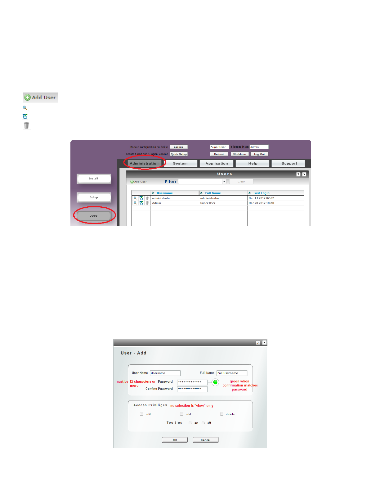
CREATING & MANAGING USERS
This section covers the creation and management of user accounts. There are four levels of user
privilege.
From login screen, enter “Administration” then “Users”
Enters the new user creation screen.
Allows the viewing of the selected user attributes.
Enters the selected user modification screen.
Deletes the selected user.
ADDING A USER
From the Users review screen, click on “Add User” icon.
User Name is the name you will enter when logging into the storage appliance.
Full Name is an additional descriptive name for the user.
The Password must be at least 12 positions; it may consist of any alpha numeric sequence
The Confirm Password entry must match the Password entered previously. The red circle will turn
green upon successful confirmation.
Access Privileges allow the user defined permissions within the management GUI. Leaving all
privilege check boxes empty will leave the user with only viewing capability.
90

XIX ALERT NOTIFICATION
The Xvos storage appliance family provides the ability to send alerts to multiple recipients based on
the alert level and the recipients’ configuration. Recipients are completely independent from user
login.
To add, change, delete or view an alert notification recipient, start from the login screen, select “Help”
and then “Alert Management”.
The Email Address should contain the complete address of the intended recipient.
There are three Alert Levels, the highest level is Critical. A level receives messages from lower
levels as well. A Critical alert level recipient will receive warnings and information messages. A
Warning alert level recipient will receive warnings and information. An Information alert level
recipient will only get informational warnings.
The Message field contains text that will be displayed in the email subject field. It should identify the
storage appliance to make it clear what unit is sending the alert. The body of the email will contain
the alert information.
Hitting the “Send test email” button will send an immediate email to verify correct configuration and
pathing.
91

XX INFORMATION, STATUS, STATISTICS & ERRORS
Main Menu
Left Column
Sub Menu
Provides core license module information
Provides specific user information
Provides disk details
Provides host connectivity information
Provides host, disk and port information for
logical volumes
Provides disk and logical volume information
for RAID sets
Provides enclosure power, cooling and disk
location information
Provides snapshot configuration information
Provides replication status, source and
destination volume information
All OS aware hardware recorded information
All IO interface configuration information
Provides information for imported iSCSI
volumes
Running log of all OS events
Device element action and error counts
Device uptime and general information
Alert recipient information
Current OS release notes
Bug log and complete system status, bug,
configuration and error report generator
richardq@email1.com,jessicab@email2.com
comma
separator
no space
no space
Status Information is available throughout the OS. Virtually every drill down screen has
indicators. Clicking on this icons supplies base information about the line in which the icon is located.
COMPLETE SYSTEM INFORMATION LOG
A complete system information package can be emailed to support buy selecting Support then
Support Log. Clicking on Send will bring up an email recipient entry screen. More than one
recipient can be entered the format must be strictly followed to successfully send the information
package.
92

Because this log contains proprietary information, it is transmitted in an encrypted format and can be
richardq@email1.com,jessicab@email2.com
comma
separator
no space
no space
opened by Xvos operating system engineers. All hardware and software information is available in
individual reports and displays listed in the table.
LOG VIEWER
The system activity log can be viewed by selecting Help then Log Viewer. Clicking on Send will
bring up an email recipient entry screen. More than one recipient can be entered the format must be
strictly followed to successfully send the information package.
93
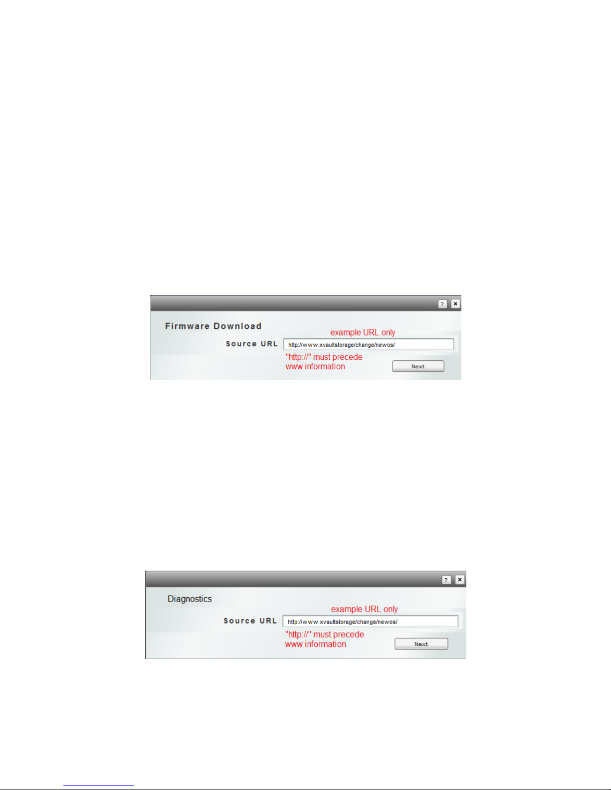
XXI UPDATES & DIAGNOSTICS
OPERATING SYSTEM UPDATES
On occasion it may be necessary to update the operating system. After a system update a reboot will
be required to enact and enable the changes. All system configuration and array data remains intact
after an OS update and reboot. The update action is access disruptive and should be scheduled.
As with any operating system upgrade it is recommended that an OS backup be performed and all
array data be backed up.
The revision update is provided via HTML download across the Internet. The specific URL for the
update is provided by technical support via email.
1. Once the OS update URL is obtained, log into the management GUI, select Support then
select Update New Version. Finally select Get New Version.
2. Enter the supplied URL and select Next.
3. The appliance will indicate, download, installation, success and then indicate a reboot is
necessary to apply changes. The appliance does not need to be rebooted immediately and
can be done later by selecting the Reboot button from the log in screen.
DIAGNOSTICS
The Diagnostic menu select is used to run diagnostics, make firmware changes, clear logs, change
configuration and retrieve unique information. All routines are loaded via HTML download. Routines
are available from the support web site and URLs dispensed from technical support email.
1. Once the routine URL is obtained, log into the management GUI, select Application then
select Tools then Diagnostics. Finally select Get New Version.
2. Enter the supplied URL and select Next.
3. The appliance will indicate, download, installation, success. Most routines do not require a
system reboot. After routine, the Xvos will indicate if a reboot is necessary. Technical support
can also indicate whether a reboot will be necessary.
94
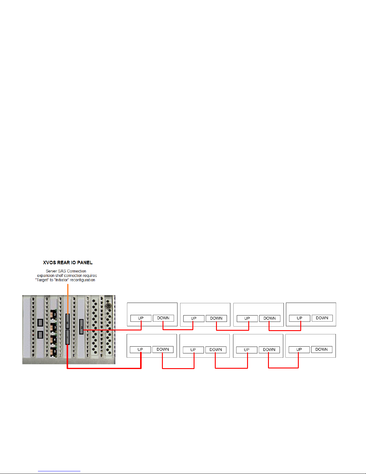
XXII ADDING EXPANSION ENCLOSURES
1st Expander
2nd Expander
3rd Expander
4th Expander
5th Expander
6th Expander
7th Expander
The Xvos XV-AMxU35 supports expansion via SAS slave enclosures. Up to twelve enclosures
external to the master enclosure are supported with proper configuration.
Only XVOS SAS expansion enclosures are supported. While Seneca enclosures are SAS standards
compliant, many manufacturers do not supply necessary information or are not mapped to the xVault
operating system so many features are not available.
Expansion shelves added after the first installation and license will require an additional license to be
added to the operating system. The expansion license is included with the enclosure. A sheet is
included with the add-on enclosure with instructions and license installation is covered in this manual.
In the rear IO panel there are three mini SAS SFF-8088 connectors. By default one connector is
configured as a target port that can be connected to a server with a SAS HBA port. The remaining
two ports are configured by default for SAS expansion shelves. The default factory configuration will
support and additional eight enclosures. To support an additional four expansion enclosures will
require reconfiguring the port from Target to Initiator mode. How to do this is covered earlier in the
manual.
Expansion enclosures cable from the master to expansion via supplied SFF-8088 daisy chain cable.
V1
It is considered a best practice to balance expansion across available SAS expansion ports.
95

1
2
default
option
Port0
“Target”
1
2
1
2
1
2
1
2
Port 1 “Initiator”
Rear Connections On Expansion Chassis
V2
Expansion shelves with disks installed and not purchased on the original order are shipped as
individual drives. Creation of a RAID set and volumes and host assignment will be required. Earlier
chapters in this manual cover the procedures.
IDENTIFYING ENCLOSURES
By default all Xvos enclosures come with a default name. It is recommended for use, service and
maintenance that unique names be assigned to each enclosure.
NAMING ENCLOSURES
1. To change enclosure Name, select the icon adjacent to the enclosure that change is
desired. Change Enclosure Name and select OK
96

97

XXIII CONFIGURING A SAS SAN
Servers
Xvos Storage Appliance
Expansion (up to 5 total enclosures)
Standard Xvos Capability
Expansion (up to 5 total enclosures)
Xvos Storage Appliance
SAS Cables (up to 3m long)
SAS Cables (up to 3m long)
Xvos with optional 16 port HBA
Xvos with optional SAS Switch
Xvos Storage Appliance
Expansion (up to 5 total enclosures)
Servers
Servers
Servers
MODE
REAR CONNECTOR
Target
0
Initiator
1
second external expansion
Initiator
2
first external expansion
A SAS SAN can be a switched connected Storage Area Network (SAN) or direct connected.
The Xvos V1 comes standard with three x4 SAS connections in the rear. Xvos v2 comes standard
with two rear ports with an option to add four more. These ports are factory configured as V1 - one
“Target” and two “Initiator” ports and V2 one “Target” and one “Initiator” “Target” ports connect to
servers. “Initiator” ports connect to disk expansion enclosures.
Configuring a SAS port to act as a “Target” or “Initiator” ports is covered earlier in this manual under
SAS PORT CONFIGURATION. See rear panel connector diagram on page x for connector
identification
V1 STANDARD PORT CONFIGURATION
98

Server SAS Connection
Master Xvos Node
SAS Drive Expansion
Standard Xvos V2 Capability
Up To Three Enclosures
Server SAS Connections
Master Xvos Node
SAS Drive Expansion
Xvos V2 With Expansion Option
Up To Three Enclosures
Xvos V2 With SAS Switching
99

XXIV Remote Management Through A Firewall
The Xvos is equipped with the ability for remote management access though local firewalls using a
reverse SSH server. The supply, configuration and maintenance of the SSH server is the
responsibility of the party(s) that wish to remotely access the Xvos storage appliance.
There are a number of open source SSH servers available. Seneca Data has tested remote access
capability through firewalls using Cygwin SSH server software. Seneca Data does not approve,
endorse or support any software products from Cygwin. The mention of Cygwin is provided as an
informational kick start only to help in determining what SSH server may best serve the user of the
Xvos storage appliance.
OPENING THE REMOTE ACCESS CONFIGURATION
1. From the login screen, select Administration, then Setup, then Remote Access Setup.
Enter appropriate information and click OK
2. Xvos subsystem will indicate successful connection to SSH server. Remote browser
administration is now possible through the SSH server.
SECURITY ADVISORY: While an SSH link is relatively secure and the addresses may not be targets,
it is highly recommended to clear all remote access information in the Xvos storage appliance after
remote access is no longer necessary and to stop the SSH service in the SSH server when remote
access is not necessary.
Seneca Data does offer BILLABLE consulting services to aid in the implementation of a reverse SSH
server
100
 Loading...