

Page 1

Page 1
SENECA s.r.l.
(Other)
This document is property of SENECA srl. Duplication and reproduction of its are forbidden
(though partial), if not authorized. Contents of present documentation refers to products and
technologies described in it. Though we strive for reach perfection continually, all technical data
contained in this document may be modified or added due to technical and commercial needs;
it’s impossible eliminate mismatches and discordances completely. Contents of present
documentation is anyhow subjected to periodical revision. If you have any questions don’t
hesitate to contact our structure or to write us to e-mail addresses as above mentioned.
USER MANUAL
RTU-LP
Ultra Low Power RTU and Datalogger, with quad band GSM/GPRS modem and
embedded I/O
Via Austria 26, PADOVA – ITALY
Tel. +39.049.8705355 – 8705359 Fax. +39.049.8706287
Web site: www.seneca.it
Customer service: supporto@seneca.it (IT), support@seneca.it
(Other)
Commercial information: commerciale@seneca.it (IT), sales@seneca.it
MI004690_101_EN
Page 2

USER MANUAL – RTU-LP-ST
2
Date
Version
Changes
03/04/2017
1.00
First Revision
12/06/2017
1.01
Added info on Alarms.
Modified Chapter “Power control for external sensors”
Page 3

USER MANUAL – RTU-LP-ST
3
Table of contents
SENECA RTU-LP ................................................................................................................ 6
PRELIMINARY INFORMATION .......................................................................................... 6
1. CHARACTERISTICS .................................................................................................... 8
1.1. RTU-LP characteristics .................................................................................................................................... 8
1.2. Digital Inputs .................................................................................................................................................. 9
1.3. Digital outputs ............................................................................................................................................... 9
1.4. Analog Inputs ................................................................................................................................................. 9
1.5. Communication Port .....................................................................................................................................10
1.6. Storage units .................................................................................................................................................10
1.7. Power supply ................................................................................................................................................10
1.8. Regulations ...................................................................................................................................................11
1.9. Default Case specifications ............................................................................................................................11
2. CONNECTIONS .......................................................................................................... 11
2.1. Power supply connections ............................................................................................................................11
2.2. Analog input connections ..............................................................................................................................12
2.3. Auxiliary voltage connections .......................................................................................................................12
2.4. Serial communication RS232 ports connections ............................................................................................13
2.5. Digital outputs connections ..........................................................................................................................13
2.6. Power control for external sensors ...............................................................................................................14
2.7. Digital inputs connections .............................................................................................................................14
3. SIGNAL LEDS ............................................................................................................ 15
Page 4

USER MANUAL – RTU-LP-ST
4
3.1. GSM led ........................................................................................................................................................15
4. DEVICE OVERVIEW ................................................................................................... 16
5. WAKE UP WINDOW ................................................................................................... 17
5.1. WAKE UP REPORT SMS .................................................................................................................................17
6. REAL TIME EVENTS .................................................................................................. 19
6.1. REAL TIME EVENTS SMS ................................................................................................................................19
6.2. REAL TIME EVENTS FTP FILE ..........................................................................................................................22
7. ANALOG INPUTS LOG FTP FILE (FILE0) ................................................................ 24
7.1. Analog Inputs log data buffering ...................................................................................................................25
8. EVENTS LOG FTP FILE (FILE1) ................................................................................ 25
8.1. Events log data buffering ..............................................................................................................................28
9. MODBUS RTU PROTOCOL ....................................................................................... 28
9.1. MODBUS RTU ADDRESSES TABLE ..................................................................................................................29
10. SUPPORTED SMS COMMANDS ........................................................................... 30
10.1. Setting the Telephone SMS Character Alphabet ............................................................................................31
10.2. CM - Change Wake-Up Window Parameters .................................................................................................31
10.3. CS - Change Analog Threshold Parameters ....................................................................................................31
10.4. CT - Change Address book Telephone numbers .............................................................................................32
10.5. AZ – Action Command ...................................................................................................................................32
10.6. AZ – Synchronize DATE/HOUR ......................................................................................................................33
10.7. CL - Change Events Label ...............................................................................................................................34
10.8. ES - SMS 0 EXTERNAL EVENT .........................................................................................................................36
11. SOFTWARE CONFIGURATION: EASY RTU-LP ................................................... 36
12. FIRMWARE UPDATE.............................................................................................. 37
Page 5

USER MANUAL – RTU-LP-ST
5
13. ENERGY ANALYSIS ............................................................................................... 37
Page 6

USER MANUAL – RTU-LP-ST
6
Seneca RTU-LP
PRELIMINARY INFORMATION
CAUTION!
Contact your telephone provider for information on GSM and GPRS service costs. It is best to
quantify log and SMS costs before setting up and installing RTU-LP.
The use of RTU-LP in data roaming (for example, abroad with an Italian SIM card) may generate
unexpected costs. Contact your telephone provider for further information.
IN NO CASE MAY SENECA OR ITS SUPPLIERS BE HELD LIABLE FOR ANY INCOMING DATA OR
PROFIT LOSSES DUE TO INDIRECT, CONSEQUENTIAL OR INCIDENTAL CAUSES (INCLUDING
NEGLIGENCE) CONNECTED WITH THE USE OR INABILITY TO USE RTU-LP, EVEN IF SENECA WAS
INFORMED OF THE POTENTIAL OF THESE DAMAGES.
SENECA, ITS SUBSIDIARIES OR AFFILIATES OR GROUP PARTNERS OR DISTRIBUTORS AND SENECA
DEALERS DO NOT GUARANTEE THAT THE FUNCTIONS FAITHFULLY MEET THE EXPECTATIONS AND
THAT LP-RTU, THEIR FIRMWARE AND SOFTWARE ARE FREE OF ERRORS OR FUNCTION
UNINTERRUPTEDLY.
SENECA HAS TAKEN THE UTMOST CARE AND CAUTION IN DRAFTING THIS MANUAL. HOWEVER,
IT MAY CONTAIN ERRORS OR OMISSIONS. SENECA SRL RESERVES THE RIGHT TO MODIFY
AND/OR VARY PARTS OF THIS MANUAL TO CORRECT ERRORS OR TO ADJUST TO PRODUCT
FEATURE CHANGES WITHOUT ANY PRIOR NOTICE.
CAUTION!
-Contact your telephone service provider for GSM and GPRS service costs especially when using
RTU-LP with a sim issued by a country other than the one in which it is used (international
roaming).
-It is best to estimate telephone costs before setting up LP-RTU.
-The cost of each SMS is set by the telephone service provider.
-Internet send/receive costs can be tied to Kbytes sent/received, a monthly ceiling included in a
package or internet connection time. Contact your telephone service provider for further
information.
Page 7

USER MANUAL – RTU-LP-ST
7
-For internet connections whose costs is associated with connection time, please remember that
communications are active for an amount of time that depends on the number of log rows to be
sent. Typically, a 2 Kbyte data log takes about 10-15 seconds (in GPRS mode) to be sent in
addition to the time necessary to establish the connection (from 5 to 30 seconds) and the time
due to any server login attempts.
-Check the data quantity sent via internet and SMS before using RTU-LP.
Please remember that mobile phone service providers also consider the entire communication
that permits file transmission (and thus data transmission overhead, the number of connection
attempts, etc.) and not just the dimensions as data traffic in each transaction.
Page 8

USER MANUAL – RTU-LP-ST
8
1. CHARACTERISTICS
1.1. RTU-LP characteristics
Supply voltage 8..30 Vdc
Digital Inputs isolation 500 Vdc
MODEM:
GSM/GPRS quad-band 850/900/1800/1900 MHz
GPRS multi slot class 10
GPRS max. 86 kbps (DL)
Coding scheme CS-1, CS-2, CS-3, CS-4
Up to 3 Years operation life with the standard 13000 mA/h @ 10,8V Battery (*)
Power Supply for external loop powered sensors (max 100 mA)
NR 4 digital inputs
NR 2 15-bit signed voltage/current programmable analog inputs
NR 2 relay digital outputs
NR 1 RS232 port
NR4 32 bits totalizers (max 1 Hz)
Data transmission on event and/or on demand (to SMS and/or to FTP server)
Datalogger internal Flash Memory: 2Mbytes
Max Analog Log speed: 30 seconds
Max Digital Log speed: 1 second
GSM status LED
Protocol on RS232: Modbus RTU Slave
32 bits ARM processor
Firmware update via RS232
(*) = With 1 SMS transmission for day, ALL Inputs OFF, No Aux Power Output, NO RS232
communication
Page 9

9
Channels number
4
Rated Voltage
7 Vdc
Rated Current
4 mA
Maximum acquisition speed (frequency)
1 Hz
Isolation from other circuits
500 V
Channels number
2
Output type
Bistable Relay (Reset and Set)
Maximum Voltage
30 Vdc
Maximum Current
1 A (resistive load)
Channels number
2
Input type
Current / Voltage configurable
Voltage input
±2V, ±20V, ±50V accuracy 0,1% FS
Current input
±20 mA accuracy 0,1% FS
Resolution
15 bit signed
Maximum Acquisition Speed
30 seconds
1.2. Digital Inputs
1.3. Digital outputs
USER MANUAL – RTU-LP-ST
1.4. Analog Inputs
Page 10

10
RS232
DB9 PORT
Protocol
Modbus RTU Slave
Internal Flash
2 Mbytes for datalogger
Internal EEprom
64 Kbytes for configuration
Voltage
8...30 Vdc
Average Power consumption
3.7 mW Average (*)
(*)
Without GSM/GPRS/RS232 transmission
ALL inputs OFF
No Aux Power Output
Standard Battery pack duration
Up to 3 Years (*)
(*)
Standard Lithium-thionyl Chloride 13000 mAh
@ 10.8V
GSM ON for 1 SMS/day
ALL inputs OFF
No Aux Power Output
1.5. Communication Port
1.6. Storage units
USER MANUAL – RTU-LP-ST
1.7. Power supply
Page 11

11
No RS232 transmission
EN61000-6-4/2002-10
Electromagnetic emission, industrial
environment.
EN61000-6-2/2006-10
Electromagnetic immunity, industrial
environment.
EN 301 511
Harmonized standard for mobile stations in the
GSM
900 and 1800 bands.
EN 301 489-1
ElectroMagnetic Compatibility standard for
radio equipment and services.
EN 301 489-7
Specific (EMC) conditions for mobile radio
equipment
(GSM 900 and 1800).
EN 60950
Safety of information Technology Equipment.
Case Dimensions
263 x 143 x 89 mm
(Without battery pack)
Protection rating
IP40
(without optional external case)
1.8. Regulations
USER MANUAL – RTU-LP-ST
1.9. Default Case specifications
2. CONNECTIONS
2.1. Power supply connections
You can supply only DC power from the battery pack, take care the "+" and "-" polarity:
Page 12

USER MANUAL – RTU-LP-ST
12
2.2. Analog input connections
Voltage and current connections can be connected like in picture:
2.3. Auxiliary voltage connections
The device can provide up to 100mA (protected) to an external sensor connected to terminals (+) and (-).
The voltage is the same of the power supply.
Page 13

USER MANUAL – RTU-LP-ST
13
2.4. Serial communication RS232 ports connections
The RS232 PORT is in standard DB9 format:
PIN 5 = GND
PIN 3 = TX
PIN 2 = RX
2.5. Digital outputs connections
The output relay is connected between terminals like in picture:
Page 14

USER MANUAL – RTU-LP-ST
14
The picture shows the DO1 and DO2 in Reset State (default).
2.6. Power control for external sensors
The RTU can switch on up to 2 sensors before read a value from the analog inputs.
It’s possible to define a delay between power ON of an external sensor and the analog acquisition (for the
external sensor wake-up time).
Seneca recommends to use an external battery (rechargeable) for power up external sensors, the power is
connected to the sensor 1 through the DO1 and to the sensor2 through DO2. There is no need to command
the DO because the firmware can power up autonomously the sensors before reading.
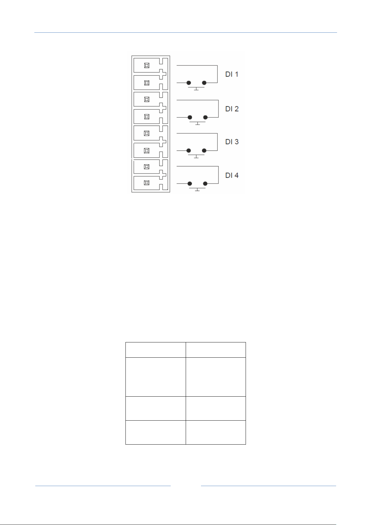
2.7. Digital inputs connections
The digital inputs can be connected like below:
Page 15
USER MANUAL – RTU-LP-ST
15
GSM LED
MEANING
OFF
GSM MODEM OFF
(RTU NOT POWERED
OR IN SLEEP STATE)
FAST FLASHING
GSM NETWORK
SEARCHING
SLOW FLASHING
GSM NETWORK
CONNECTED
A 32 bits counters is available for each digital input.
The maximum acquisition speed is 1 Hz.
Digital Inputs have a 500V galvanic isolation between others circuits.
3. SIGNAL LEDS
3.1. GSM led
The GSM status led has the following meanings:
Page 16

USER MANUAL – RTU-LP-ST
16
4. DEVICE OVERVIEW
The RTU-LP-ST is an ultra low power device, the RTU is always sleeping (with the modem OFF) but when an
event is registered the RTU can Wake-up and send data.
It’s also possible to configure the device to send data at a time interval or wake up the board at fixed time
leaving the modem ON for minutes (for receiving commands).
RTU-LP-ST device can send the following type of data:
1) SMS with a Wake up Report
2) SMS with a Real Time Event
3) FTP file with a Real Time Event
4) FTP log file with the analog inputs (File 0)
5) FTP log file with events (File 1)
RTU-LP-ST device can receive the following type of data:
1) SMS with a command
2) Configuration through the RS232 port
Page 17

USER MANUAL – RTU-LP-ST
17
5. WAKE UP WINDOW
When the RTU is in sleep mode the SMS cannot be reached because the modem is switched off for energy
saving purpose. For sending command SMS to the RTU it’s possible to configure a wake-up window where
the RTU can switch ON the modem and read/execute the command SMS.
When the RTU will wake up can also send a SMS with a Wake up Report.
5.1. WAKE UP REPORT SMS
When a wake up window is set it’s also possible to send from the RTU a wake up report SMS of this type:
RP D>abcd00ef 1> ±gggggg 2> ±hhhhh T: dddddddddd eeeeeeeeee ffffffffff gggggggggg BAT:xx.xV
TEMP:xx.xC CSQ Med,Max,Min / ddmmyyhhmm:RTUCODE
Where:
D> digital values
a=in1 value
b=in2 value
c= in3 value
d= in4 value
e=Out1 value
f= Out2 value
1> AIN1 value
gggggg= AIN1 value in % from 0 (0%) to 10000 (100.00%)
2> AIN2 value
Hhhhhh = AIN2 value in % from 0 (0%) to 10000 (100.00%)
Page 18

USER MANUAL – RTU-LP-ST
18
T: totalizers values:
dddddddddd = Totalizer 1 value
eeeeeeeeeee = Totalizer 2 value
ffffffffff = Totalizer 3 value
gggggggggg= Totalizer 4 value
BAT: Battery Voltage
xx.xV battery Voltage measured with modem in ON state
TEMP: Temperature
xx.xC Temperature in °C
CSQ: GSM Field
Medium Filed, maximum Field, minimum Field
Field level: 0=NO SIGNAL, 1=LOW, 2=MED, 3=HIGH
ddmmyyhhmm:
day month year hours minutes at send time
RTUCODE:
RTU numeric code
For example:
RP D> 11110010 1> +1797 2> -2500 T: 0 3354 1144 0 BAT:10.6V TEMP:22.4C CSQ 1,1,1 / 0405171555:0001
In1=In2=in3=in4 = High
Out1 = Set
Out2 = Reset
Analog 1 = 17.97%
Analog 2 = -25.00%
Totalizer1 = 0
Totalizer2 = 3354
Totalizer3 = 1144
Totalizer4 = 0
Page 19

USER MANUAL – RTU-LP-ST
19
EVENT NUMBER
DESCRIPTION
00
DIN1 : Switched to logic level 0
01
DIN2 : Switched to logic level 0
02
DIN3 : Switched to logic level 0
Battery Voltage = 10.6V
Temperature = 22.4°C
GSM Field Minimum Value =1
GSM Field Medium Value =1
GSM Field Maximum Value =1
Send Timestamp = 04 /May /2017 at 15:55
6. REAL TIME EVENTS
Real Time events can be configured for to be sent immediately afterwards the event, or to be
logged in a “FILE1” file.
When a real time event is configured to be sent immediately, it’s possible to use a SMS and/or a
FTP file.
Caution!
The RTU will send real time events only when there is a change state.
6.1. REAL TIME EVENTS SMS
When an event is registered in RTU will switch ON the modem and can immediately send a SMS.
The SMS it’s of this type:
EV xx EVENT_LABEL D>abcd00ef 1> ±gggggg 2> ±hhhhh T: dddddddddd eeeeeeeeee ffffffffff gggggggggg
BAT:yy.yV TEMP:xx.xC CSQ Med,Max,Min / ddmmyyhhmm:RTUCODE
Where:
xx is the event number (see table)
Page 20

USER MANUAL – RTU-LP-ST
20
03
DIN4 : Switched to logic level 0
04
DIN1 : Switched to logic level 1
05
DIN2 : Switched to logic level 1
06
DIN3 : Switched to logic level 1
07
DIN4 : Switched to logic level 1
08
AIN1 < MIN
09
AIN2 < MIN
10
AIN1 > MAX
11
AIN2 > MAX
12
TOT1 > Threshold 1
13
TOT2 > Threshold 1
14
TOT3 > Threshold 1
15
TOT4 > Threshold 1
16
TOT1 > Threshold 2
17
TOT2 > Threshold 2
18
TOT3 > Threshold 2
19
TOT4 > Threshold 2
20
TOT1 Reset/Overflow (0000)
21
TOT2 Reset/Overflow (0000)
22
TOT3 Reset/Overflow (0000)
23
TOT4 Reset/Overflow (0000)
24
SMS 0 (event SMS0)
26
Timer Seconds (count of seconds)
29
Timer Day
30
RTU LOW BATTERY
31
RTU RESET
EVENT_LABEL is the event text that is configured with Easy LP-RTU or SMS
D> digital values
Page 21

21
a=in1 value
b=in2 value
c= in3 value
d= in4 value
e=Out1 value
f= Out2 value
1> AIN1 value
gggggg= AIN1 value in % from 0 (0%) to 10000 (100.00%)
2> AIN2 value
Hhhhhh = AIN2 value in % from 0 (0%) to 10000 (100.00%)
USER MANUAL – RTU-LP-ST
T: totalizers values:
dddddddddd = Totalizer 1 value
eeeeeeeeeee = Totalizer 2 value
ffffffffff = Totalizer 3 value
gggggggggg= Totalizer 4 value
BAT: Battery Voltage
yy.yV battery Voltage measured with modem in ON state
TEMP: Temperature
xx.xC Temperature in °C
CSQ: GSM Field
Medium Filed, maximum Field, Minimum Field
Field level: 0=NO SIGNAL, 1=LOW, 2=MED, 3=HIGH
ddmmyyhhmm:
day month year hours minutes at send time
RTUCODE:
RTU numeric code
Page 22

USER MANUAL – RTU-LP-ST
22
For example:
EV 31 REBOOT D> 11110010 1> +1797 2> -2500 T: 0 3354 1144 0 BAT:10.6V TEMP:22.4C CSQ 1,1,1 /
0405171555:0001
This means:
Event 31 = RTU RESET
Text Label for Event 31 = “REBOOT”
In1=In2=in3=in4 = High
Out1 = Set
Out2 = Reset
Analog 1 = 17.97%
Analog 2 = -25.00%
Totalizer1 = 0
Totalizer2 = 3354
Totalizer3 = 1144
Totalizer4 = 0
Battery Voltage = 10.6V
Temperature = 22.4°C
GSM Field Minimum Value =1
GSM Field Medium Value =1
GSM Field Maximum Value =1
Send Timestamp = 04 /May /2017 at 15:55
6.2. REAL TIME EVENTS FTP FILE
The FTP file name is :
RTUNAMERTUCODE_YYYY-MM-DD_HH-MM_KKKK.csv
Page 23

USER MANUAL – RTU-LP-ST
23
Where:
RTUNAME: is the RTU Name configured with Easy RTU-LP Software
RTUCODE: is the numerical RTU code configured with Easy RTU-LP Software
YYYY-MM-DD_HH-MM: it’s the date/hour of the event
KKKK: is a progressive alphanumerical code
A file name example is:
MRTU10001_2017-05-08_11-49_042B.csv
The FTP file content is the same of the SMS in text format:
For example:
EV 31 REBOOT D> 11110010 1> +1797 2> -2500 T: 0 3354 1144 0 BAT:10.6V TEMP:22.4C CSQ 1,1,1 /
0405171555:0001
This means:
Event 31 = RTU RESET
Text Label for Event 31 = “REBOOT”
In1=In2=in3=in4 = High
Out1 = Set
Out2 = Reset
Analog 1 = 17.97%
Analog 2 = -25.00%
Totalizer1 = 0
Totalizer2 = 3354
Totalizer3 = 1144
Totalizer4 = 0
Battery Voltage = 10.6V
Temperature = 22.4°C
GSM Field Minimum Value =1
Page 24

USER MANUAL – RTU-LP-ST
24
GSM Field Medium Value =1
GSM Field Maximum Value =1
Send Timestamp = 04 /May /2017 at 15:55
7. ANALOG INPUTS LOG FTP FILE (FILE0)
The RTU can be configured for log the two Analog inputs with a minimum Log time of 30 seconds.
The Analog Inputs File0 Log file can only be sent to an FTP server, the file is a text file in a standard csv
format (comma-separated values).
The log can be sent in a report every N minutes (with N <= 1 minute).
Note that the log is sent N minutes after the modem is switched off.
For example if the log must be sent every 10 minutes we can obtain:
FIRST LOG SENT AT 12:00 -> COMMUNICATION TIME FOR SENDING THE LOG 1 MINUTE -> MODEM SWITCH
OFF AT 12:01
SECOND LOG SENT AT 12:01+10minutes= 12:11 -> TIME FOR SEND THE LOG 1 MINUTE -> MODEM SWITCH
OFF AT 12:12
THIRD LOG SENT AT 12:12+10minutes=12:22 -> TIME FOR SEND THE LOG 1 MINUTE -> MODEM SWITCH
OFF AT 12:23
…
A single file can contain a maximum of 64 Data Rows so more than one file report can be created (for
example sending a File0 Report every 120 minutes with analog inputs sampled at 30s will generate
120*2=240 Rows of data, so will be created 4 files).
The FTP file name is :
RTUNAMERTUCODE_YYYY-MM-DD_HH-MM_KKKK_File0.csv
Where:
RTUNAME: is the RTU Name configured with Easy RTU-LP Software
RTUCODE: is the numerical RTU code configured with Easy RTU-LP Software
YYYY-MM-DD_HH-MM: it’s the date/hour of the dispatch
Page 25

USER MANUAL – RTU-LP-ST
25
DATE
TIME
AIN1
AIN2
08/05/2017
13.48.09
1797
2500
08/05/2017
13.48.39
1797
2500
08/05/2017
13.49.09
1797
2500
08/05/2017
13.49.39
1798
2500
08/05/2017
13.50.09
1797
2500
08/05/2017
13.50.39
1798
2500
08/05/2017
13.51.09
1798
2500
08/05/2017
13.51.39
1797
2500
08/05/2017
13.52.09
1798
2500
08/05/2017
13.52.39
1798
2500
08/05/2017
13.53.09
1797
2500
KKKK: is a progressive alphanumerical code
File0: is a constant
An example file name is:
MRTU10001_2017-05-08_13-48_042C_File0.csv
The File contents is of this type:
….
Where AIN1 and AIN2 are in % values /100.
So for example in the first Row the AIN1 = 17,97% of the full scale and the AIN2 = 25.00% of the full scale
Note the 30s timestamp difference between two rows.
7.1. Analog Inputs log data buffering
If there is a network or FTP server fail, the RTU can buffer not sent data to the internal flash. The RTU will
try for 3 times before return to sleep, when there is a new connection the RTU will continue to send data
from the oldest value.
The first time the RTU will re-connect, only the not sent data will be send.
You must wait the second connection for try to re-align the log with the actual date/time.
8. EVENTS LOG FTP FILE (FILE1)
The Events File1 Log file can only be sent to an FTP server, the file is a text file in a standard csv format
(comma-separated values).
Page 26

USER MANUAL – RTU-LP-ST
26
DATE
TIME
EVENT
AIN1
AIN2
TOT1
TOT2
TOT3
TOT4
09/05/2017
15.11.56
80000000 0 0 0 0 0 0
09/05/2017
15.11.56
40000000 0 0 0 0 0 0
The log can be sent in a report every N minutes (where N is configurable from the Software Easy LP-RTU)
but is sent only if at least one event is happened in the report time.
Note that the log is sent N minutes after the modem switch off.
For example if the log must be sent every 10 minutes we can obtain:
FIRST LOG SENT AT 12:00 -> TIME FOR SEND THE LOG 1 MINUTE -> MODEM SWITCH OFF AT 12:01
SECOND LOG SENT AT 12:01 +10minutes = 12:11 -> TIME FOR SEND THE LOG 1 MINUTE -> MODEM SWITCH
OFF AT 12:12
THIRD LOG SENT AT 12:12 +10minutes =12:22 -> TIME FOR SEND THE LOG 1 MINUTE -> MODEM SWITCH
OFF AT 12:23
…
A single file can contain a maximum of 64 Data Rows so more than one file1 report can be created.
The FTP file name is :
RTUNAMERTUCODE_YYYY-MM-DD_HH-MM_KKKK_File1.csv
Where:
RTUNAME: is the RTU Name configured with Easy RTU-LP Software
RTUCODE: is the numerical RTU code configured with Easy RTU-LP Software
YYYY-MM-DD_HH-MM: it’s the date/hour of the dispatch
KKKK: is a progressive alphanumerical code
File0: is a constant
An example file name is: MRTU10001_2017-05-08_13-48_042C_File1.csv
The File contents is of this type:
Where Event can be obtained from the table below:
Page 27

USER MANUAL – RTU-LP-ST
27
EVENT
EQUIVALENT EVENT NR
DESCRIPTION
1
00
DIN1 : Switched to logic
level 0
2
01
DIN2 : Switched to logic
level 0
4
02
DIN3 : Switched to logic
level 0
8
03
DIN4 : Switched to logic
level 0
10
04
DIN1 : Switched to logic
level 1
20
05
DIN2 : Switched to logic
level 1
40
06
DIN3 : Switched to logic
level 1
80
07
DIN4 : Switched to logic
level 1
100
08
AIN1 < MIN
200
09
AIN2 < MIN
400
10
AIN1 > MAX
800
11
AIN2 > MAX
1000
12
TOT1 > Threshold 1
2000
13
TOT2 > Threshold 1
4000
14
TOT3 > Threshold 1
8000
15
TOT4 > Threshold 1
1 0000
16
TOT1 > Threshold 2
2 0000
17
TOT2 > Threshold 2
4 0000
18
TOT3 > Threshold 2
8 0000
19
TOT4 > Threshold 2
10 0000
20
TOT1 Reset/Overflow
(0000)
20 0000
21
TOT2 Reset/Overflow
(0000)
Page 28

USER MANUAL – RTU-LP-ST
28
40 0000
22
TOT3 Reset/Overflow
(0000)
80 0000
23
TOT4 Reset/Overflow
(0000)
100 0000
24
SMS 0 (event SMS0)
400 0000
26
Timer Seconds (count of
seconds)
2000 0000
29
Timer Day
4000 0000
30
RTU LOW BATTERY
8000 0000
31
RTU RESET
8.1. Events log data buffering
If there is a network or FTP server fail, the RTU can buffer not sent data to the internal flash. The RTU will
try for 3 times before return to sleep, when there is a new connection the RTU will continue to send data
from the oldest value.
The first time the RTU will re-connect, only the not sent data will be send.
You must wait the second connection for try to re-align the log with the actual date/time.
9. MODBUS RTU PROTOCOL
The modbus RTU protocol is available from the RS232 Port.
The communication parameters are:
19200 Baud, 8 data bit, parity None.
The Modbus slave addess is 1.
The modbus function code supported are:
03 Read Holding Registers (Max 16 registers)
04 Read Input Registers (Max 16 registers at a time)
20 Read File Record (Read of a File record)
06 Write Single Register
Page 29

USER MANUAL – RTU-LP-ST
29
ADDRRESS
OFFSET
TAG
REGISTER TYPE
RO/RW
INFO
40001
0
CH01_MEASURE
Signed 16 bits
RO
Analog Channel 1 value (in Scale
%)
From -10000 (-100.00%) to
+10000 (+100.00 %)
40002
1
CH02_MEASURE
Signed 16 bits
RO
Analog Channel 2 value (in Scale
%)
From -10000 (-100.00%) to
+10000 (+100.00 %)
40003
2
DIGITAL IN_OUT
Unsigned 16 bits
RO
Bit 0 (LSB) Digital Input 1 value
Bit 1 Digital Input 2 value
Bit 2 Digital Input 3 value
Bit 3 Digital Input 4 value
Bit 4 Not Used
Bit 5 Not Used
Bit 6 Digital Output 1 value
Bit 7 Digital Output 2 value
Bit 8 TOT1 > MIN
Bit 9 TOT2 > MIN
Bit 10 TOT3 > MIN
Bit 11 TOT4 > MIN
Bit 12 TOT1 > MAX
Bit 13 TOT2 > MAX
Bit 14 TOT3 > MAX
Bit 15 (MSB) TOT4 > MAX
40004
3
INTERNAL USE
-
-
-
40005
4
BATTERY VOLTAGE
Unsigned 16 bits
RO
Battery voltage in V*10
For example 100 = 10.0V
Note that the Battery voltage is
measured only when the modem
is switched ON
40006
5
TEMPERATURE
Signed 16 Bits
RO
Temperature value in °C*10
For example 240 = 24.0°C
16 Write Multiple Registers (Max 16 registers)
9.1. MODBUS RTU ADDRESSES TABLE
Page 30

USER MANUAL – RTU-LP-ST
30
40007
40008
6 7 TOTALIZER 1 LSW
TOTALIZER 1 MSW
Unsigned 32 Bits
RO
Totalizer 1 value
40009
40010
8 9 TOTALIZER 2 LSW
TOTALIZER 2 MSW
Unsigned 32 Bits
RO
Totalizer 2 value
40011
40012
10
11
TOTALIZER 3 LSW
TOTALIZER 3 MSW
Unsigned 32 Bits
RO
Totalizer 3 value
40013
40014
12
13
TOTALIZER 4 LSW
TOTALIZER 4 MSW
Unsigned 32 Bits
RO
Totalizer 4 value
40101
100
MACHINE_ID
Unsigned 16 Bits
RO
Internal Code
40102
101
FW CODE
Unsigned 16 Bits
RO
Firmware Version
41043
1042
ACTIONS
Unsigned 16 Bits
RW
Actions Registers
1 = OUT1 reset
2 = OUT2 reset
4 = OUT1 set
8 = OUT2 set
16 =OUT1 toggle
32 = OUT2 toggle
68 = OUT1 start impulse
132 = OUT2 start impulse
256= TOT1 Reset
512 = TOT2 Reset
1024 = TOT3 Reset
2048 = TOT4 Reset
10. SUPPORTED SMS COMMANDS
All SMS commands must terminate with a date/hour.
The date/hour filed is not controlled by the RTU but must be a valid value.
Page 31

USER MANUAL – RTU-LP-ST
31
10.1. Setting the Telephone SMS Character Alphabet
Some Smartphones send SMS with UNICODE characters instead of using the GSM alphabet.
RTU-LP only runs SMS commands with GSM alphabet.
In most cases, SMS characters are set to AUTO alphabet by default.
If the RTU does not recognise any SMS command, check the alphabet used by the phone.
For Android smartphones:
Press the Message icon -> Others -> Settings -> Other Settings -> SMS -> Change writing -> GSM alphabet
10.2. CM - Change Wake-Up Window Parameters
The “CM” SMS message can be used for change the Wake-up window parameters:
CM a bb bb ccccc f ddmmyyhhmm
Where:
a = Wake-up window frequency (1 = every day, 2 = every 2 days,…)
bb bb = hh mm of the wake-up
ccccc = Wake-up window duration in seconds
f = report send frequency (1= every wake up, 2 = every 2 wake up, 3 = every 3 wake up, 4 = Never)
ddmmyyyyhhmm = sending date and sending time
The RTU response is:
CM a bb bb ccccc f /ddmmyyhhmm:RTUCODE
Example of usage:
CM 1 14 33 120 1 0205171102
10.3. CS - Change Analog Threshold Parameters
The “CS” SMS message can be used for change the Threshold for analog inputs:
CS ddddd eeeee fffff ggggggggggg ddmmyyhhmm
Where:
ddddd = Analog 1 MAXIMUM THRESHOLD (in % of the scale, for example 8000 = 80.00%)
Page 32

USER MANUAL – RTU-LP-ST
32
eeeee = Analog 1 MINIMUM THRESHOLD (in % of the scale, for example 8000 = 80.00%)
fffff = Analog 2 MAXIMUM THRESHOLD (in % of the scale, for example 8000 = 80.00%)
kkkkk = Analog 2 MINIMUM THRESHOLD (in % of the scale, for example 8000 = 80.00%)
ddmmyyyyhhmm = sending date and sending time
The RTU response is:
CS ±ddddd ±eeeee 2> ±fffff ±kkkkk /ddmmyyhhmm:RTUCODE
Example of usage:
CS 5000 1000 4000 500 0205171102
10.4. CT - Change Address book Telephone numbers
The “CT” SMS message can be used for change the telephone numbers that the RTU use for sending SMS:
CT aaaaaaaaaaaaaaaaaa bbbbbbbbbbbbbbbb ddmmyyhhmm
Where:
aaaaaaaaaaaaaaa = is the first Telephone number (without the “+” symbol)
bbbbbbbbbbbbbb = is the second Telephone number (without the “+” symbol)
ddmmyyyyhhmm = sending date and sending time
The RTU response is:
CT aaaaaaaaaaaaaaaaaa bbbbbbbbbbbbbbbb /ddmmyyhhmm:RTUCODE
Example of usage:
CT 39328123456789 39338456786452 1005171102
Change the numbers used from the RTU to send SMS with +39328123456789 +39338456786452
10.5. AZ – Action Command
The “AZ” SMS message can be used for sending command to the RTU:
AZ aaa ddmmyyhhmm
Where aaa is the action code:
Page 33

USER MANUAL – RTU-LP-ST
33
ACTION CODE
INFO
1
OUT 1 RESET
2
OUT 2 RESET
4
OUT 1 SET
8
OUT 2 SET
16
OUT 1 TOGGLE
32
OUT 2 TOGGLE
68
OUT 1 START PULSE
132
OUT 2 START PULSE
256
TOTALIZER 1 RESET TO 0
512
TOTALIZER 2 RESET TO 0
1024
TOTALIZER 3 RESET TO 0
2048
TOTALIZER 4 RESET TO 0
65535
RTU RESET
ddmmyyyyhhmm = sending date and sending time
The RTU response is:
AZ OK /ddmmyyhhmm:RTUCODE
Example of usage:
AZ 4 1005171102
Execute a Digital Output 1 SET
10.6. AZ – Synchronize DATE/HOUR
The “AZ” SMS message can be used also for sync date/hour using an offset:
AZ ±aaaa±MM±dd±hh±mm±ss ddmmyyhhmm
Where:
Page 34

USER MANUAL – RTU-LP-ST
34
EVENT NUMBER
DESCRIPTION
00
DIN1 : Switched to logic level 0
01
DIN2 : Switched to logic level 0
02
DIN3 : Switched to logic level 0
Add or subtract ±aaaa years to actual date
Add or subtract ±MM months to actual date
Add or subtract ±dd months to actual date
Add or subtract ±hh hours to actual time
Add or subtract ±mm minutes to actual time
Add or subtract ±ss seconds to actual time
ddmmyyyyhhmm = sending date and sending time
The RTU response is:
AZ OK /ddmmyyhhmm:RTUCODE
Example of usage:
AZ +0000+00+00+01+30+00 1005171102
Add 1h and 30m to actual time
AZ +0000+00+00-01-30+00 1005171102
Subtract 1h and 30m to actual time
10.7. CL - Change Events Label
The “CL” SMS message can be used for changing the text label linked to the event NR:
CL aa newlabel ddmmyyhhmm
Where:
aa = Event Number from table:
Page 35

USER MANUAL – RTU-LP-ST
35
03
DIN4 : Switched to logic level 0
04
DIN1 : Switched to logic level 1
05
DIN2 : Switched to logic level 1
06
DIN3 : Switched to logic level 1
07
DIN4 : Switched to logic level 1
08
AIN1 < MIN
09
AIN2 < MIN
10
AIN1 > MAX
11
AIN2 > MAX
12
TOT1 > Threshold 1
13
TOT2 > Threshold 1
14
TOT3 > Threshold 1
15
TOT4 > Threshold 1
16
TOT1 > Threshold 2
17
TOT2 > Threshold 2
18
TOT3 > Threshold 2
19
TOT4 > Threshold 2
20
TOT1 Reset/Overflow (0000)
21
TOT2 Reset/Overflow (0000)
22
TOT3 Reset/Overflow (0000)
23
TOT4 Reset/Overflow (0000)
24
SMS 0 (external event SMS)
26
Timer Seconds (count of seconds)
29
Timer Day
30
RTU LOW BATTERY
31
RTU RESET
newlabel = new text label
ddmmyyyyhhmm = sending date and sending time
Page 36

USER MANUAL – RTU-LP-ST
36
The RTU response is:
CL aa newlabel /ddmmyyhhmm:RTUCODE
Example of usage:
CL 0 D01_LOW 1005171102
Change the actual event 0 text label with “D01_LOW”
10.8. ES - SMS 0 EXTERNAL EVENT
The “ES” SMS message can be used for obtain the external event 24 that will cause a real time event
SMS/FTP file (if configured).
So this SMS is used for knowing the RTU state on demand:
ES 0 ddmmyyhhmm
Where:
0 = constant
ddmmyyyyhhmm = sending date and sending time
The RTU response is:
ES OK /ddmmyyyyhhmm:RTUCODE
After that a SMS real time event will be generated from the RTU
Example of usage:
ES 0 1005171102
Generate an external real time event NR 24
11. SOFTWARE CONFIGURATION: EASY RTU-LP
For configuring the RTU-LP-ST you must use the Easy RTU LP software and the “CONF” cable (supplied).
You can download the free software from the www.seneca.it website in the RTU-LP-ST section.
Page 37

USER MANUAL – RTU-LP-ST
37
12. FIRMWARE UPDATE
In order to include new functions, the system includes a firmware update option.
For updating the firmware use the Easy RTU-LP software and the “UPDATE” cable (supplied).
For updating the firmware the firmware update cable must be used.
CAUTION!
-BEFORE UPDATING firmware, copy the current configuration.
-Once the firmware is updated, the previous setup may be deleted so the RTU must be reconfigured.
13. ENERGY ANALYSIS
The RTU-LP battery duration depends from the user configuration.
The standard 10,8V lithium battery can supply 12500 mAh at 10,8V.
It’s best in the calculation to use the 80% of the full battery capacity = 10400 mAh.
The RTU Consumption with all inputs OFF and Analog Inputs measured at 30s without powering the
external sensors is:
0.375 mA average at 10.8V.
In these conditions, the RTU will work for about:
10400 mAh/0.375mAh= 27733 hours = 1155 days = more than 3 years
When the RTU send an SMS event the consumption calculation is:
About 90 seconds for sending 1 SMS (with GSM Field = 3/3), in this condition the RTU consumption is:
21mA average at 10.8V
So about 21mA*(90seconds/3600seconds in 1h)=0.525 mAh
So for acquiring and sending 1 SMS for day the total consumption is:
Page 38

USER MANUAL – RTU-LP-ST
38
0.525 mAh + (0.375mA*24h)=9.525 mAh
And so, sending one SMS every day the total consumption is :
10400 mAh/9.525mAh for day= more than 1091 days = about 3 years
CAUTION!
If the GSM field is low the RTU can try up to 3 times to send a SMS or a file in FTP.
For the send SMS energy calculation (0.525mAh) the GSM field is supposed to be the maximum (3/3) with
no retry.
 Loading...