

Page 1
1
USER MANUAL
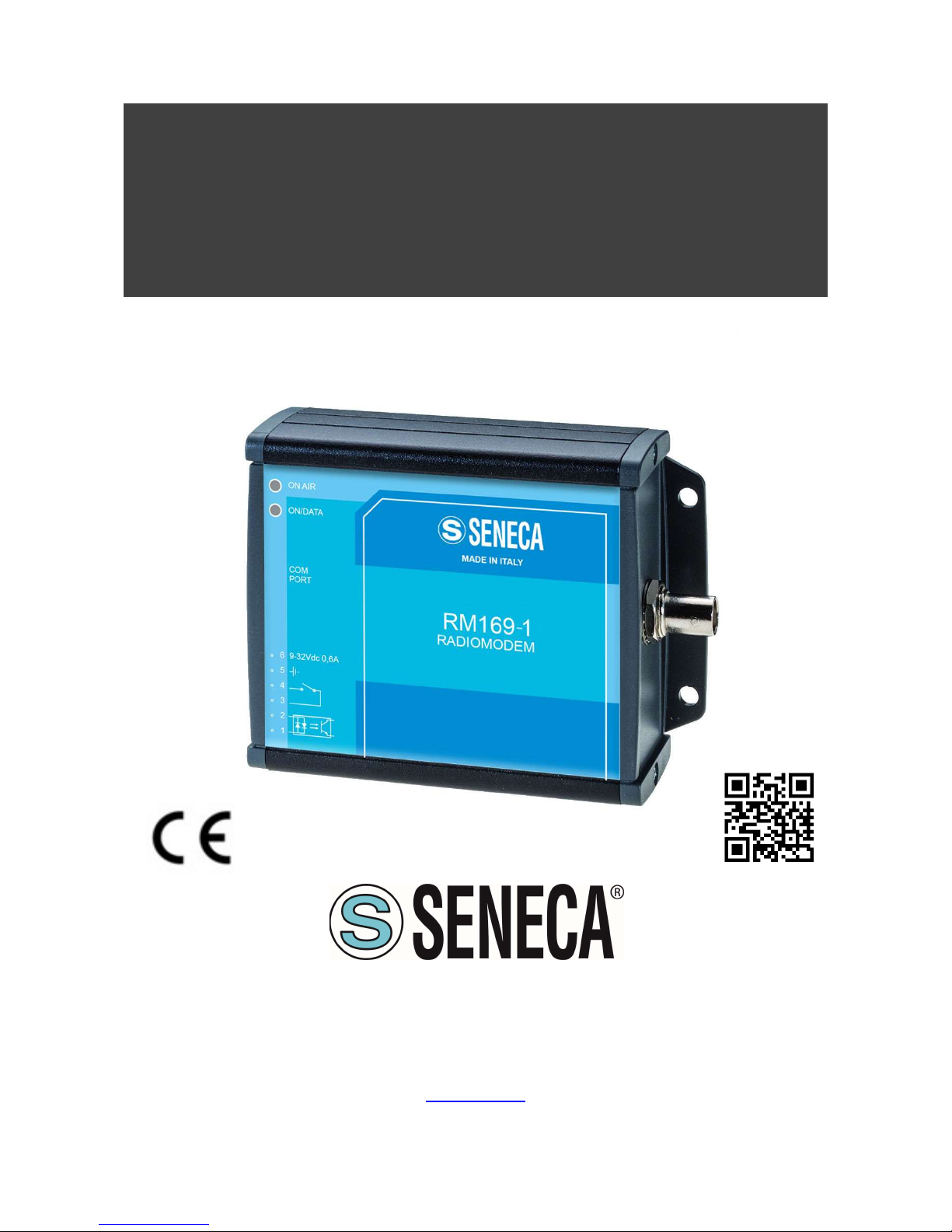
RM169-1
RADIOMODEM 169MHz with RS232/RS485 interface and
complies with the Directive 2014/53/EU (RED)
SENECA S.r.l.
Via Austria, 26 – 35127 – PADOVA (PD) - ITALY
Tel. +39 049.8705359 – 8705355 Fax +39 049.8706287
www.seneca.it
Page 2

User Manual
RM169-1
ALL RIGHTS RESERVED. NO PART OF THIS PUBLICATION MAY
BE REPRODUCED WITHOUT PRIOR PERMISSION.
www.seneca.it
Doc. MI004760-E Rev. 0 Pag. 2
TABLE OF CONTENTS
1. DISCLAIMER ................................................................................................................ 3
2. TECHNICAL SUPPORT ............................................................................................... 3
3. RESTRICTIONS ON USE ............................................................................................. 3
4. TECHNICAL SPECIFICATION ..................................................................................... 5
5. WARRANTY – LIABILITY OF THE PRODUCT............................................................ 6
6. WARNING AND SAFETY INSTRUCTIONS ................................................................. 7
7. DISPOSAL OF WASTE BY USERS IN PRIVATE HOUSEHOLDS WITHIN THE
EUROPEAN UNION ............................................................................................................ 7
8. GENERAL DESCRIPTION ........................................................................................... 8
9. INSTALLATION .......................................................................................................... 10
9.1. Mechanical .............................................................................................................................................................................10
9.2. Electrical (wiring) ..................................................................................................................................................................10
9.3. Antenna ..................................................................................................................................................................................11
10. CONFIGURATION ...................................................................................................... 12
10.1. System requirements ............................................................................................................................................................12
10.2. Configuration via RS232 serial port ....................................................................................................................................12
10.3. Configurazione via USB with S117P1 (RS232/USB converter) .........................................................................................12
11. OPERATING MODES AND SETTINGS ..................................................................... 15
11.1. MIRROR OPERATING MODE ...............................................................................................................................................15
11.2. MODBUS LOW ENERGY OPERATING MODE ....................................................................................................................17
11.3. MODBUS OPERATING MODE ..............................................................................................................................................21
11.4. RADIOMODEM OPERATING MODE .....................................................................................................................................26
12. UTILITY ....................................................................................................................... 30
12.1. Link Test ................................................................................................................................................................................30
13. APPENDICE ............................................................................................................... 32
13.1. MODBUS REGISTER .............................................................................................................................................................32
13.2. MODBUS LOW ENERGY REGISTER ...................................................................................................................................32
Page 3

User Manual
RM169-1
Pag. 3 Doc. MI004760-E Rev. 0
www.seneca.it
ALL RIGHTS RESERVED. NO PART OF THIS PUBLICATION MAY
BE REPRODUCED WITHOUT PRIOR PERMISSION.
1. DISCLAIMER
All rights to this manual are owned solely by SENECA Srl (referred to in this user guide as SENECA).
All rights reserved. The copying of this manual (without the written permission from the owner) by printing,
copying, recording or by any other means, or the full or partial translation of the manual to any other language,
including all programming languages, using any electrical, mechanical, magnetic, optical, manual or other
methods or devices is forbidden.
SENECA reserves the right to change the technical specifications or functions of its products, or to discontinue
the manufacture of any of its products or to discontinue the support of any of its products, without any written
announcement and urges its customers to ensure, that the information at their disposal is valid.
SENECA software and programs are delivered ”as is”. The manufacturer does not grant any kind of warranty
including guarantees on suitability and applicability to a certain application. Under no circumstances is the
manufacturer or the developer of a program responsible for any possible damages caused by the use of a
program. The names of the programs as well as all copyrights relating to the programs are the sole property of
SENECA. Any transfer, licensing to a third party, leasing, renting, transportation, copying, editing, translating,
modifying into another programming language or reverse engineering for any intent is forbidden without the
written consent of SENECA.
2. TECHNICAL SUPPORT
Our website www.seneca.it contains many useful information, user guides and configuration software and
technical documents always update to the latest version.
If you have technical problems or cannot find the required information in the provided documents, contact our
Technical Support by email at [email protected] or by phone +39 049 8705359.
3. RESTRICTIONS ON USE
SENECA PRODUCTS HAVE NOT BEEN DESIGNED, INTENDED NOR INSPECTED TO BE USED IN ANY
LIFE SUPPORT RELATED DEVICE OR SYSTEM RELATED FUNCTION NOR AS A PART OF ANY OTHER
CRITICAL SYSTEM INCLUDED AERONAUTICAL / AEROSPACE APPLICATION.
SENECA PRODUCTS ARE GRANTED NO FUNCTIONAL WARRANTY IF THEY ARE USED IN ANY OF THE
APPLICATIONS MENTIONED.
SENECA RM169-1 radio modems have been designed to operate on frequency ranges as SRD (Short Range
Device), the exact use of which differs from one region and/or country to another. The user of a radio modem
must take care that the device is not operated without the permission of the local authorities on frequencies
other than those specifically reserved and intended for use without a specific permit.
SENECA RM169-1 can be used in the following countries with E.R.P. and duty cycle limitation, either on licence
free channels or on channels where the operation requires a licence. More detailed information is available at
the local frequency management authority.
Page 4
User Manual
RM169-1
ALL RIGHTS RESERVED. NO PART OF THIS PUBLICATION MAY
BE REPRODUCED WITHOUT PRIOR PERMISSION.
www.seneca.it
Doc. MI004760-E Rev. 0 Pag. 4
Country allowed
(4)
ALB-AND-AUT-BEL-BIH-BLR-BUL-CYP-CZE-D-DNK-E-EST-F-FIN-G-GRC
-
HNG
-
HOL-HRV-I-IRL-
ISL-LIE
-
LTU-LUX-LVA-MDA-MKD-MLT-MNE-NOR-POL-POR-ROU-RUS-S-SRB-SUI-SVK-SVN-TUR-UKR
Allowed use according to ERC Recommendation 70-03
RM169-1 Frequency (MHz) Annex
(1)
E.R.P
(2)
Duty Cycle
(3)
Country
(4)
with
restriction of use
169,400 – 169,475 1 ≤ 500 mW ≤ 1 % BLR-RUS-UKR
169,400 – 169,475 2 ≤ 500 mW ≤10 % BLR-RUS-UKR
NOTE:
Before to install the device check always the latest version of ERC Recommendation 70-03 in order to verify
any restriction and limitation in terms of E.R.P and Duty Cycle
(1) Annex 1.xxx refer to SRD (Short Range Device), Annex 2 refer to Tracking, Tracing and Data Acquisition.
(2) E.R.P. = Max Effective Radiated Power allowed from radiomodem and associated antenna takes into
consideration transmitter power output, transmission line attenuation, RF connector insertion losses and
antenna gain
(3) Duty Cycle is defined as the ratio, expressed as a percentage, of the maximum transmitter “on” time on
one carrier frequency, relative to a one hour period
(4) The CEPT country codes can be seen under http://www.cept-org/cept/cept-country-codes
Page 5
User Manual
RM169-1
Pag. 5 Doc. MI004760-E Rev. 0
www.seneca.it
ALL RIGHTS RESERVED. NO PART OF THIS PUBLICATION MAY
BE REPRODUCED WITHOUT PRIOR PERMISSION.
4. TECHNICAL SPECIFICATION
Operating data
Label
Description
Value
VS
(EXT)
Power supply, voltage range
9,0 →
32 Vdc
PS
(EXT)
Max power
max. 5 W
I
Sleep
Sleeping current (Power Off)
≤ 150
μA @ 12Vdc
PRF
RF transmission power
Livello H
500 mW
Livello M
150 mW
Livello L
25 mW
RX
SENS
Receiver sensitivity
≤ -
105 ± 3 dBm
RF
MOD
Modulation mode
***F1D
CH Canalization
12,5
– 25 –
50 kHz
BR Radio
Baud Rate on radio channel
4.800
– 9.600
– 19.200 bps
Buffer
Memory buffer
1024 bytes
Z
I/O ANT
Antenna impedance
50
Digital Input Rating digital input
5 –
24 Vdc
3 – 20 Vac
Z
DIGITAL-INP
Digital input
impedence
2,2 k
Digital
Output
Digital output rating
Normally Open
(NO)
24 Vac @ 0,5 A
32 Vdc @ 1A
I
A,B LINES
Max current out at RS
-
485 serial port
± 60 mA
BR DTE
Baud Rate serial port
1.200
→ 57.600 bps
WARNING Exceed the maximum operating value below (continuous and/or temporary) can damage the
device.
Maximum operating data
Label
Description
Value
V
S(EXT)
Max power supply voltage
32 Vdc
V
DIG-INP
Digital input, max voltage
24 Vdc / 20 Vac
V
DIG-OUT
Digital output, max voltage
32 Vdc / 28
Vac VP RS
Max peak voltage at the ports A/B RS
-
485
(1)
± 32 Vdc
I
A,B LINES
Max current out at the A/B RS
-
485 ± 200 mA
T
OPERATING
Operating temperature range
-30°C +60
°C
T
STORAGE
Storage temperature range
-40°C +85
°C
NOTE:
(1) Impulse time < 100 millisecond.
Page 6

User Manual
RM169-1
ALL RIGHTS RESERVED. NO PART OF THIS PUBLICATION MAY
BE REPRODUCED WITHOUT PRIOR PERMISSION.
www.seneca.it
Doc. MI004760-E Rev. 0 Pag. 6
5. WARRANTY – LIABILITY OF THE PRODUCT
Supplier represents and warrants that products are manufactured in accordance with the applicable
specifications and are free from defects in materials and workmanship. The warranty, valid for a period of 12
months of use, maximum 18 months from the date of delivery, shall not cover defects caused by accident,
Buyer’s negligence, improper use or maintenance or by any other reason beyond Supplier’s control.
Buyer shall have 10 (ten) working days following receipt of products to inspect the products and to notify to
Supplier in writing any defects or non-compliance. In the event that any shipment of products is not accepted by
Buyer due to any non-conformity with the specifications, or as a result of a cause occurred prior to placement
thereof with the carrier, Buyer shall, if so indicated in writing by the Supplier, promptly return some samples or
the full shipment that was rejected by Buyer at Buyer’s costs.
Supplier, at its own discretion, shall, within a reasonable period, considering the entity of the complaint: (i) send
a replacement shipment of products conforming, or (ii) credit Buyer a sum equal to the value of the defective or
non-conforming products. This warranty overwrites all legal warranties for defects and compliance and exempts
Supplier from any other responsibility for the supplied products; in particular, Buyer shall not be entitled to any
requests for compensation or price reductions.
If one of the products sold by the Supplier to the Buyer is defective, the Buyer will send it, at its own expense,
at the headquarters of the Italian Supplier. The product will be repaired or replaced by the Supplier, at no costs
to the Buyer.
The Buyer will pay all the shipping costs for the product repaired or replaced and sent back to the Buyer.
The Buyer will bear all costs related to disassembly, assembling and transportation of the product, and any
damage caused by the "machinery inactivity".
Supplier shall indemnify Buyer against any liability of the products claims asserted by third parties relating to
damages sustained as a result of a defective products. In such case Supplier shall reimburse Buyer exclusively
within the limits, terms and conditions of the products liability insurance policy held by Supplier. Buyer shall not
make any oral or written representations which vary from the specifications, operating instructions, labels or
representations given or made by Supplier with respect to the products. If any liability is incurred because of
such varying representations, Buyer holds Supplier harmless with respect to any such representations.
In no event shall Supplier be liable for any indirect, incidental, exemplary or consequential damages, including
without limitation any claim for damages based on lost revenues or profits, however caused.
In no event shall the Supplier be liable for any costs or damages arising from any act or omission of Buyer,
including, without limitation, relating to the modification, handling, storage and marketing of Products by Buyer
or to Buyer’s failure to provide its employees, agents and customers or other third parties with adequate
instruction as to the proper handling and use of Products.
In this respect we hereby confirm that our products are not designed for nuclear applications neither for
aircraft/aerospace industries. For the above mentioned applications both warranty and insurance coverage do
not apply..
Page 7
User Manual
RM169-1
Pag. 7 Doc. MI004760-E Rev. 0
www.seneca.it
ALL RIGHTS RESERVED. NO PART OF THIS PUBLICATION MAY
BE REPRODUCED WITHOUT PRIOR PERMISSION.
6. WARNING AND SAFETY INSTRUCTIONS
Read these safety instructions carefully before using the product:
Warranty will be void, if the product is used in any way that is in contradiction with the instructions given in this
manual, or if the radio modem housing has been opened or tampered with.
The radio modem is only to be operated at frequencies allocated by local authorities, and without exceeding the
given maximum allowed output power ratings and duty cycle. SENECA and its distributors are not responsible,
if any products manufactured by it are used in unlawful ways.
The devices is complies with Directive 2014/53/UE (RED) and Directive 2011/65/UE (ROHS)
The devices mentioned in this manual are to be used only according to the instructions described in this manual.
Faultless and safe operation of the devices can be guaranteed only if the transport, storage, operation and
handling of the devices is appropriate. This also applies to the maintenance of the products.
Place the antenna at a height greater than or equal to 2 m above the general public walkway that gives general
public access.
Do not install the equipment close to a heat source or in damp conditions and direct sunlight is also to be avoided.
The device must not be exposed to aggressive chemical agents or solvents likely to damage the plastic or
corrode the metal parts.
The device must not be exposed directly to dusty environment.
Maintenance should only be carried out by qualified persons.
For your own safety, you must ensure that the equipment is switched off before carrying out any work on it.
Any electrical connection of the product must be equipped with a protection device against voltage spikes and
short-circuits
7. DISPOSAL OF WASTE BY USERS IN PRIVATE HOUSEHOLDS WITHIN THE
EUROPEAN UNION
According to Directive 2012/19/EU of the European Union on waste electrical and
electronic equipment (WEEE) this product must not be disposed off with your other
household waste, it is your responsibility to dispose of your waste by taking it to a
collection point designated for the recycling of electrical and electronic appliances.
Separate collection and recycling of your waste at the time of disposal will contribute
to conserving natural resources and guarantee recycling that respects the environment
and human health.
For further information concerning your nearest recycling centre, please contact your nearest local authority/town
hall offices.
Page 8
User Manual
RM169-1
ALL RIGHTS RESERVED. NO PART OF THIS PUBLICATION MAY
BE REPRODUCED WITHOUT PRIOR PERMISSION.
www.seneca.it
Doc. MI004760-E Rev. 0 Pag. 8
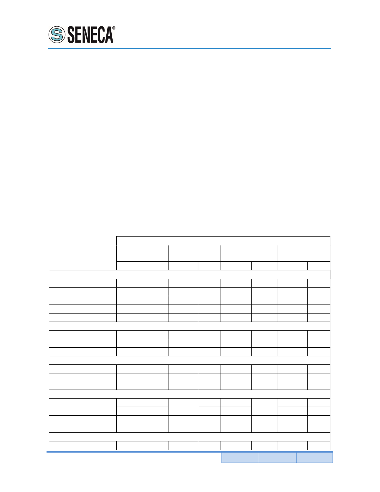
8. GENERAL DESCRIPTION
RM169-1 includes 1 optically isolated digital inputs and 1 digital relay outputs, an RS-232/485 serial interface,
this radiomodem is fully configurable via software. The embedded inputs and outputs allow the RM169-1
radiomodem to be used in data acquisition and remote control applications.
RM169-1 has 4 operating modes that are software programmable: radiomodem, mirror point to point, Modbus
slave, or Modbus master, allowing greater flexibility in the field.
RM169-1 uses routing tables to obtain fewer collisions in complex networks and can also be used as a Modbus
hub, allowing 8 Modbus modules (inputs and/or outputs) to be connected through the RS-485 port. (RM169-1
will power these modules).
Data Encryption 128bit AES (Advanced Encryption Standard) ensures transmitted data security.
A power-saving function is built in, to activate inputs only when required, allowing for extended battery life.
Function available for each operating mode.
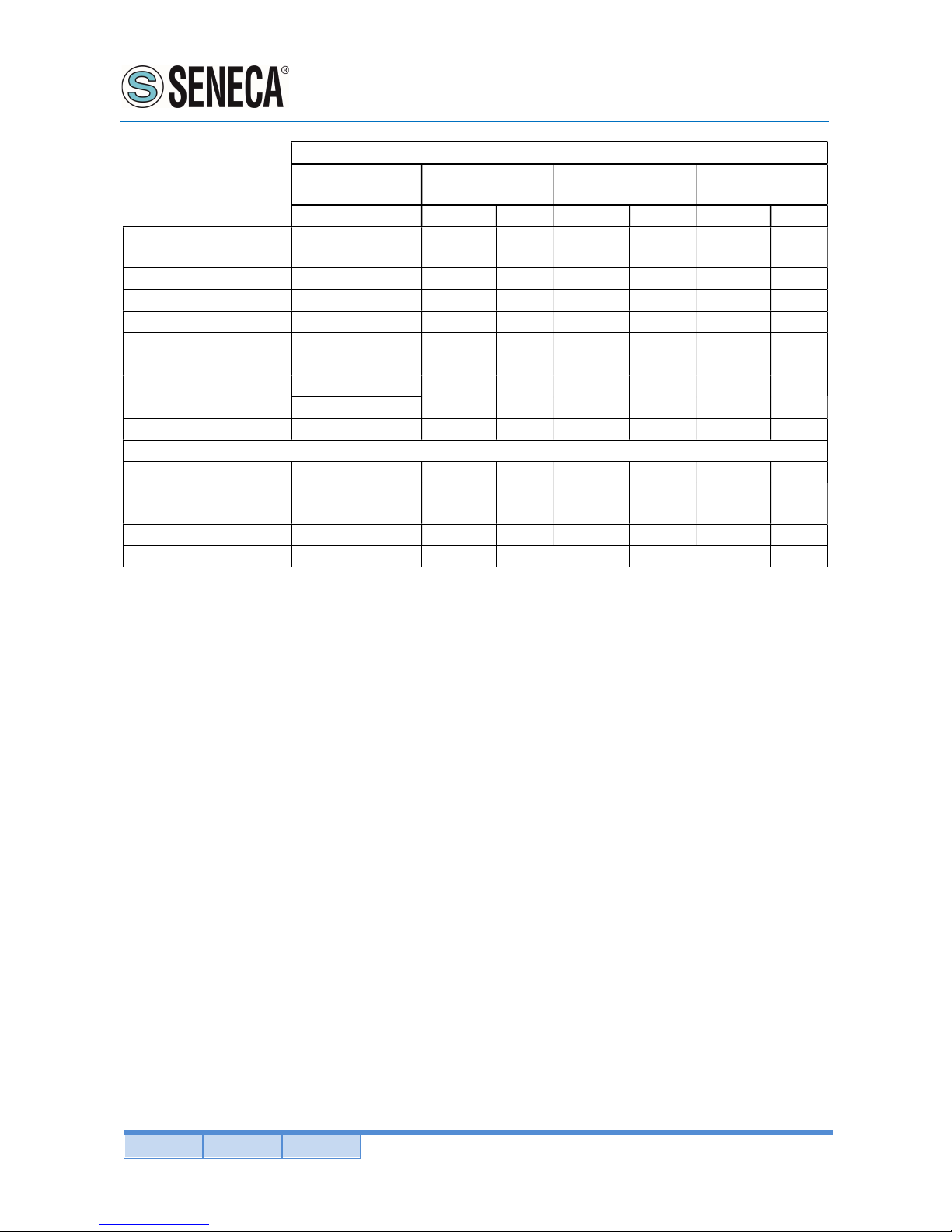
CHARACTERISTICS AND FUNCTIONALITY AVAILABLE
Yes= you can choose and/or modify the function
No = the function doesn’t exist or is not enabled
Operating mode
Radio
ModBus
Standard
ModBus Low
Energy
Mirror
modem
Master
Slave
Master
Slave
Master
Slave
Radio
Channel spacing
Yes Yes Yes Yes Yes Yes Yes
RF channel Yes Yes Yes Yes Yes Yes Yes
Frequency Agility
Yes Yes Yes Yes Yes Yes Yes
Listen Before Talk Yes Yes Yes No No No No
RF power
Yes Yes Yes Yes Yes Yes Yes
Serial Port RS485
Bit Rate
Yes Yes Yes Yes Yes No Yes
Parity bit Yes Yes Yes Yes Yes No Yes
DTX Time
Yes Yes Yes Yes Yes No Yes
Auxiliary
Safety option
Yes Yes Yes No No Yes Yes Contact of relè
selectable NC/NO
Yes Yes Yes No No Yes Yes
Input & Output
Digital inputs
Yes
No
Yes Yes
No
Yes Yes
(n° 1) (n° 1) (n° 1) (n° 1) (n° 1)
Digital outputs
Yes
No
Yes Yes
No
Yes Yes
(n° 1) (n° 1) (n° 1) (n° 1) (n° 1)
Data
AES encrytption Yes Yes Yes Yes Yes No No
Page 9
User Manual
RM169-1
Pag. 9 Doc. MI004760-E Rev. 0
www.seneca.it
ALL RIGHTS RESERVED. NO PART OF THIS PUBLICATION MAY
BE REPRODUCED WITHOUT PRIOR PERMISSION.
Operating
mode
Radio
ModBus
Standard
ModBus Low
Energy
Mirror
modem Master Slave Master Slave Master Slave
Routing Table Yes, 1 route
Yes, 255
route
No No No
Yes, 1
route
Yes, 1
route
Broadcasting Yes No No No No No No
Address from DTE
Yes No No No No No No
Address to DTE Yes No No No No No No
Rx address for Tx
Yes No No No No No No
Request of ACK Yes No No No No No No
Set number of retries
Yes
No No No No No No
(max. 255)
NAK to DTE
Yes No No No No No No
Other
Diagnostic Yes No No
No No
No Yes
(always
active)
(always
active)
Power Save Yes Yes Yes No No No No
Link Test Yes No No No No No No
Page 10
User Manual
RM169-1
ALL RIGHTS RESERVED. NO PART OF THIS PUBLICATION MAY
BE REPRODUCED WITHOUT PRIOR PERMISSION.
www.seneca.it
Doc. MI004760-E Rev. 0 Pag. 10
9. INSTALLATION
9.1. Mechanical
The device must be installed in a location that is sufficiently ventilated so that there is no risk of internal heating.
Place the device against a flat, firm and stable surface. It is not recommendable to install the radio modem on a
strongly vibrating surface. Suitable dampening and/or isolation materials should be used in cases where the
installation surface will be subjected to vibration.
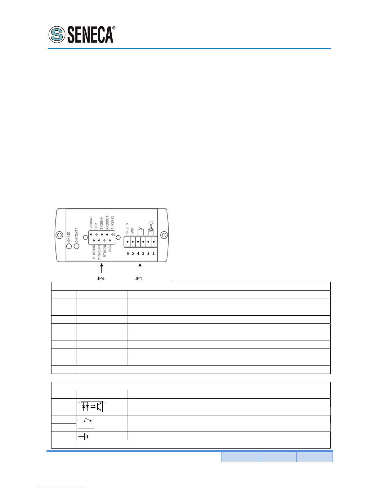
9.2. Electrical (wiring)
To prevent damage both the radio modem and any terminal devices must always be switched OFF before
connecting or disconnecting the serial connection cable. It should be ascertained that different devices used
have the same ground potential. Before connecting any power cables the output voltage of the power supply
should be checked.
The product has no disconnecting device. An external disconnecting device must be installed. This must be
close to the equipment. Provide an adequate termination resistance on the RS485 serial line.
To by supplied by class II (LPS) certified AC/DC adaptor.
JP4 Connector
PIN Label
Description
1
A RS485
RS-
485 (line A)
2
RXD (OUT)
Data output
3
TXD (IN)
Data input
4
DTR Data Terminal Ready
5
GROUND
Ground (GND)
6
N.C. Not connected
7
RTS Request To Send
8 CTS Clear To Send
9
A RS485
RS-
485 (line B)
JP1 Connector
PIN Label
Description
1 Optoisolated digital input
2
3
Digital output normally open (NO)
4
5
Ground (GND)
6 9-32V 0,6A
Power supply (9
- 32 VDC, 0.6A)
Page 11

User Manual
RM169-1
Pag. 11 Doc. MI004760-E Rev. 0
www.seneca.it
ALL RIGHTS RESERVED. NO PART OF THIS PUBLICATION MAY
BE REPRODUCED WITHOUT PRIOR PERMISSION.
9.3. Antenna
L’antenna deve essere installata in spazio libero e posto ad una distanza di almeno 10 cm da materiali conduttori.
Quando l’antenna è installata all’esterno è essenziale connettere lo schermo del cavo a terra. Raccomandiamo
di utilizzare parafulmini. Il kit di protezione scelto deve permettere il collegamento a terra del cavo coassiale.
Page 12
User Manual
RM169-1
ALL RIGHTS RESERVED. NO PART OF THIS PUBLICATION MAY
BE REPRODUCED WITHOUT PRIOR PERMISSION.
www.seneca.it
Doc. MI004760-E Rev. 0 Pag. 12
10. CONFIGURATION
Download from SENECA web site (www.seneca.it) the latest version of configuration software at this link
https://www.seneca.it/products/rm169-1 in the related DOWNLOAD section.
The configuration must be done through serial port RS232 or RS485 interface with a RS485/USB converter such
as SENECA S117P1 or equivalent.
10.1. System requirements
Operative system supported: Windows 98 SE, Windows ME, Windows2000, Windows XP, Windows Vista,
Windows 7, Windows 8, Windows 10.
Minimum screen resolution: 800 x 600 dpi.
10.2. Configuration via RS232 serial port
1) Connect the serial port of the radio modem to the computer communication port with a NO Null Modem cable
and open the configuration utility.
2) In Options Menu select the appropriate computer Communication Port.
3) Connect, with the proper polarity, a power supply source to the radio modem.
4) Press the "Turn ON" button on the configuration program. On the radiomodem the entering into configuration
state is confirmed by a led color change from off to orange. On the configurator this change it is confirmed by a
variation in the text of the button from "Turn ON" to "Turn OFF" and by the activation of the Read and Write
buttons. If, when "Turn ON" is pressed, the button blink green, wait the end of the blink before proceding with
normal operation.
10.3. Configurazione via USB with S117P1 (RS232/USB converter)
1) Install the appropriate driver as explained in the user manual of the S117P1 interface.
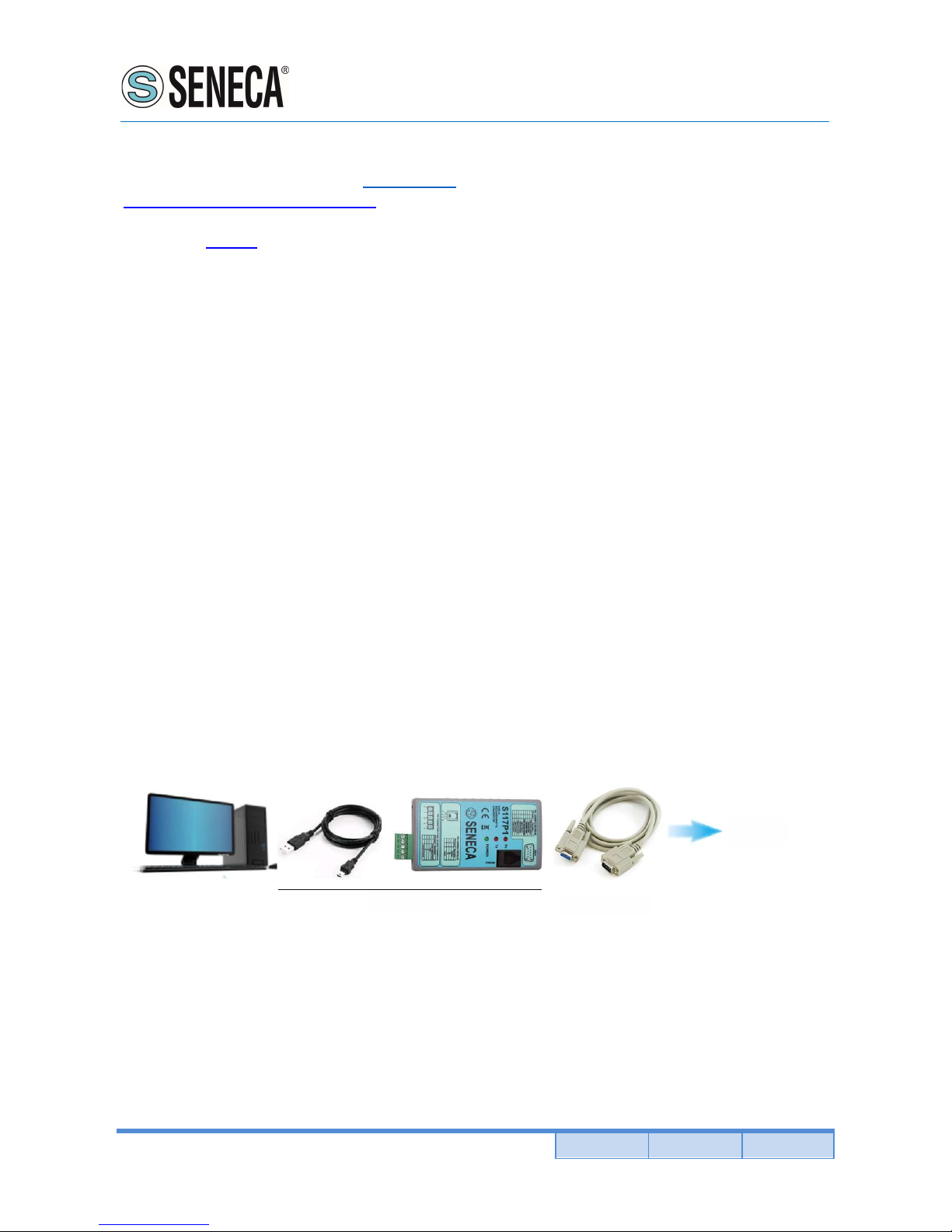
2) Connect the interface S117P1 to a personal computer by a USB cable with type A connector (PC side) and
microUSB connector (interface side).
3) Go into the options menu of the Configuration (Options) and select the serial port (Serial port selector).
4) Using a cable with a DB9 connector on one side, connect the radio modem to the interface board according
to the diagram (see the figure below).
RM169-1
CS-DB9M-DB9F
S117P1
5) Power up the radio modem.
6) To enter in configuration mode you must follow this step: turn off the radio modem, click on the "Turn On"
button of the configurator and turn on the radio modem within 4 seconds from the push of the "Turn On" button
(while the button is flashing green).
Note: When the program starts, the buttons "Next Page", "Load Default" and "Write", remain inhibited until you
choose the operating mode between: "Mirror", "Low energy", "Modbus standard" or "Radiomodem". This choice
is done by pressing the left mouse button on the relevant button in the configurator. Even the reading of the
parameters of a unit involves the activation of the buttons inhibited at program startup.
Page 13

User Manual
RM169-1
Pag. 13 Doc. MI004760-E Rev. 0
www.seneca.it
ALL RIGHTS RESERVED. NO PART OF THIS PUBLICATION MAY
BE REPRODUCED WITHOUT PRIOR PERMISSION.
The selection among the various fields of the configuration program is carried out with the TAB key or by
positioning the mouse pointer over the field and clicking once with the left button. A function is activated when,
in the relative box, the check mark is present.
Function of the Buttons common to all modes
Read:
Reads the data from the radiomodem.
Write:
Writes the configuration data into the radiomodem.
Load Default:
Resets all fields to their default values.
Next Page:
Allows you to move to the second page. You can go to the second page only if you have selected an operative
mode between the four possible ones.
Exit:
Close the configurator program.
Note:
The buttons Write, Load Default and Next Page are activated only if you have selected an operation mode
between the four possible ones, or if you load a configuration file (using the menu File, Open), or if the
configuration is read by a radio modem unit.
Toolbar:
The Toolbar on the upper side of the screen contains File, Options and Help Menus. Each menu can be opened
as a normal Windows menu using both mouse and keys.
The different menus have the following functions:
FILE menu:
- Open (path/filename): Loads an existing file in the configurator program.
- Save (path/filename): Updates an existing file after a change in the parameters.
- Save As (path/filename): Creates a new file containing all configuration data. The user can select an adequate
filename and choose the destination folder. The default destination folder has the same path as the executable
program.
- Exit: close the configurator program.
Options menu:
- Serial port selector: Open the serial port selection box. A port number between 1 and 16 can be chosen.
- Model: RM169-1
- Canalization
12,5 KHz: the width of the radio channel is 12.5 KHz and the speed of radio data is 4800 bps.
25 KHz: the width of the radio channel is 25 KHz and the speed of radio data is 9600 bps.
50 KHz: the width of the radio channel is 50 KHz and the speed of radio data is 19200 bps.
Page 14

User Manual
RM169-1
ALL RIGHTS RESERVED. NO PART OF THIS PUBLICATION MAY
BE REPRODUCED WITHOUT PRIOR PERMISSION.
www.seneca.it
Doc. MI004760-E Rev. 0 Pag. 14
Help menu:
- Index F1: Open the Help file.
- About: Display the version information about the configuration software..
Page 15
User Manual
RM169-1
Pag. 15 Doc. MI004760-E Rev. 0
www.seneca.it
ALL RIGHTS RESERVED. NO PART OF THIS PUBLICATION MAY
BE REPRODUCED WITHOUT PRIOR PERMISSION.
11. OPERATING MODES AND SETTINGS
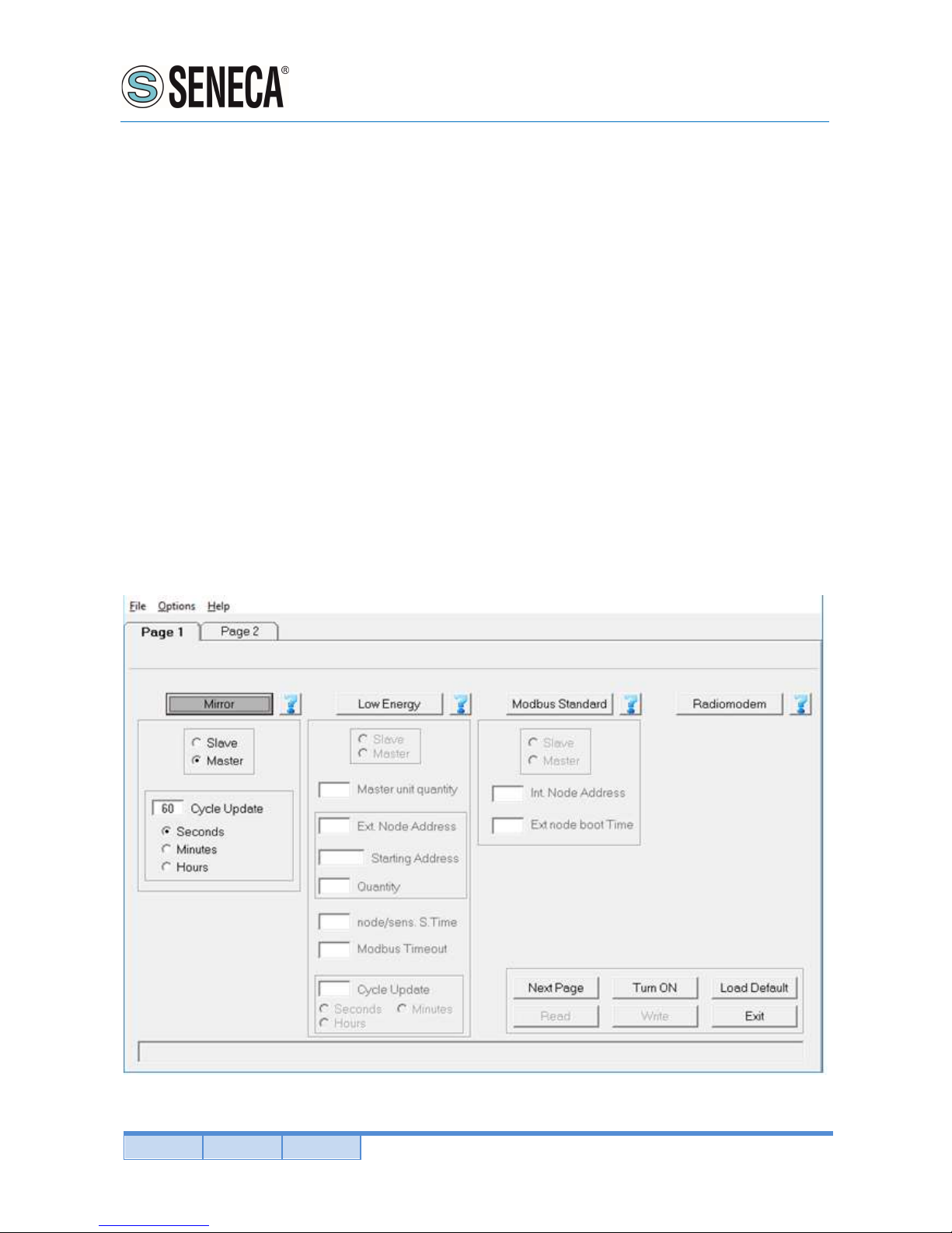
11.1. MIRROR OPERATING MODE
In Mirror mode, the status of digital inputs of an unit is replicated on digital outputs of a remote unit and vice
versa. In this operating mode, data communication on the serial line is not allowed. The mirror mode can only
work between two radiomodem units (point-to-point) and can use digipeater (up to 8) to extend the route of the
radio link. The initiative of the transmission is always taken from the master device and it is triggered by two
different events:
1) The change of the state of the Master’s digital inputs (every input of the four available modes may trigger this
event).
2) The expiration of the timer dedicated to the periodic sending of the data (cycle update).
On the Slave unit, every time a packet is received, the diagnostic parameters are sent over the serial line. The
sent parameters are:
1) Status of four digital inputs and two digital outputs of the Master unit.
2) Value (in milliampere) of two analog inputs and two analog outputs of the master unit.
3) Value of the battery voltage of the Master unit.
4) RSSI value related to the last packet received by the Master unit.
In the Slave unit it is also possible to read the diagnostic parameters at any time by sending the command "at?"
or "AT? to the serial port. The radio modem will respond with the parameters described above adding to these
the value of the elapsed time since the reception of the last packet transmitted by the Master.
Page 16
User Manual
RM169-1
ALL RIGHTS RESERVED. NO PART OF THIS PUBLICATION MAY
BE REPRODUCED WITHOUT PRIOR PERMISSION.
www.seneca.it
Doc. MI004760-E Rev. 0 Pag. 16
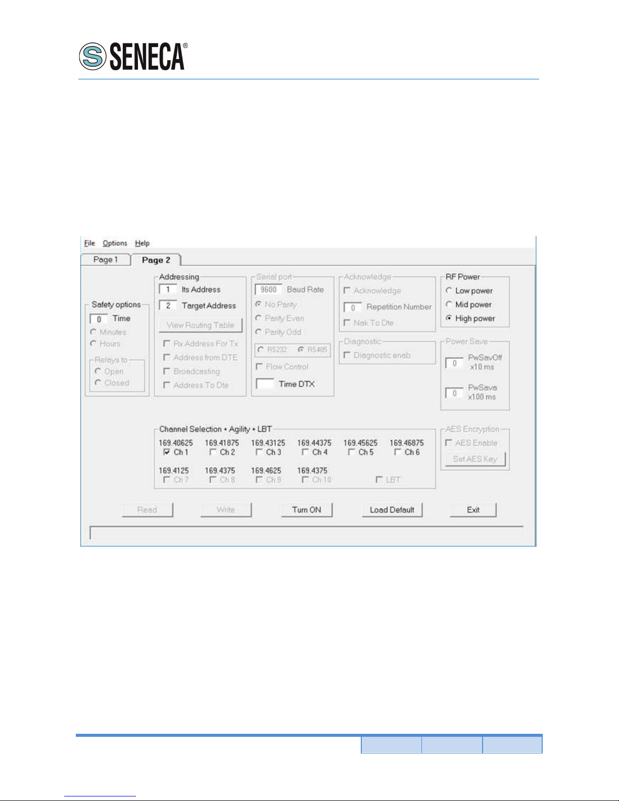
Slave / Master:
Allows you to select the functionality of the radiomodem between Master and Slave. The unit configured as
Master uses the energy saving and transmits as a result of events. The unit configured as a Slave is always
active and never takes the initiative of the transmission.
When a device is used as digipeater the device must be settled as Slave.
Cycle Update:
In this field the time of the periodical transmission is set. The time base is selectable between seconds, minutes
or hours. The time range can vary from one second (minimum) to 255 hours (maximum). In this field you cannot
insert a value less than the value of the time interval assigned to the field "Sensor stabilization time".
Safety options (frame):
Time: sets the value of the safety timer whose time base is selectable between minutes and hours. If the radio
doesn’t receive a valid packet within the selected time interval, the digital output (relay) is forced to a condition
chosen in the field "Relays to Open/Closed". To disable the functionality of the safety timer set the value of
"Time" to zero.
Minute: the value of "Time" is expressed in minutes.
Hours: the value of "Time" is expressed in hours.
Relays to Open: when the safety timer expires, the relay contact of digital output will be forced to open.
Relays to Closed: when the safety timer expires, the relay contact of digital outputs will be forced to closed.
Its address:
It is the value of the address of this radiomodem. It is advisable to configure each radiomodem with a unique
address.
Page 17

User Manual
RM169-1
Pag. 17 Doc. MI004760-E Rev. 0
www.seneca.it
ALL RIGHTS RESERVED. NO PART OF THIS PUBLICATION MAY
BE REPRODUCED WITHOUT PRIOR PERMISSION.
Target address:
Contains the value of the destination address and must be equal to the address of the other unit. Example:
Master unit: Its address = 1; Target address = 2. Slave Unit: Its address = 2; Target address = 1.It is evident
that the addresses of the two fields (its own address and the and target address) are reversed between Master
and Slave. In the case of using digipeaters, they must have a different address and the target value is
uninfluenced.
System Code & Digipeater address (double click of the mouse on "Target" or [Enter] key):
When the focus is on the Target field, pressing the "Enter" key on the keyboard or by double clicking the mouse,
a window opens in which you can enter the system code and the addresses of the digipeater path to include in
the radio link. On the involved units the system code must be the same.
RF Power:
Allows the choice between three different levels of power: High, Medium, Low. If the RSSI value displayed in
diagnostic parameters of the Slave unit is good (-70 dBm or better), and if the low power of the Master unit is
an important factor, it is advisable to choose a medium or low power level.
Channel selection + Agility + LBT:
In this box you choose the radio channel to be used. If you want to use the agility feature (transmission on the
less noisy channel among the active channels), you can select more than one radio channel. The maximum
number of active channels is dependent on the canalization setting. It is mandatory that in the same network
all the radiomodems use the same radio channels. In Mirror mode the LBT function cannot be activated.
11.2. MODBUS LOW ENERGY OPERATING MODE
In this modality the network is composed of one Slave unit and one or more (up to 16) Master unit. The Slave
unit is connected to a PC (or PLC) on which there is a running SCADA software. The slave device is always in
reception, never takes the initiative of the transmission and transmits only in response to a packet received from
a Master unit. The Master units send a packet to the Slave unit using the modbus RTU Protocol. The function
"Write multiple registers (function code 0x10) is used. The transmission of the Master units is triggered by two
events:
1) The expiration of the timer dedicated to the periodical sending;
2) A change of digital inputs on the Master radiomodem.
On each Master device, it is possible to connect, by the RS485 interface, an external Modbus node (Modbus
device that can read digital or analog inputs) in order to extend the number of monitored signals.
Note: You cannot use the digital inputs of an external modbus node to trigger the transmission on the
radiomodem.
In the Master unit, when a transmission is triggered, the value of the digital input is first acquired, the external
node (if present) is read, then the radio modem sends the packet consisting of the collected data.
The slave device receives the packet, controls it, and if there are no errors, it sends the data (payload) to the
SCADA application via the RS485 interface. At this point the SCADA software, connected to the Slave
radiomodem, sends the response packet, which is transmitted back to the Master unit. At the end of the
Communication, the Master unit returns in sleep mode, waiting for a new transmission event.
Page 18
User Manual
RM169-1
ALL RIGHTS RESERVED. NO PART OF THIS PUBLICATION MAY
BE REPRODUCED WITHOUT PRIOR PERMISSION.
www.seneca.it
Doc. MI004760-E Rev. 0 Pag. 18
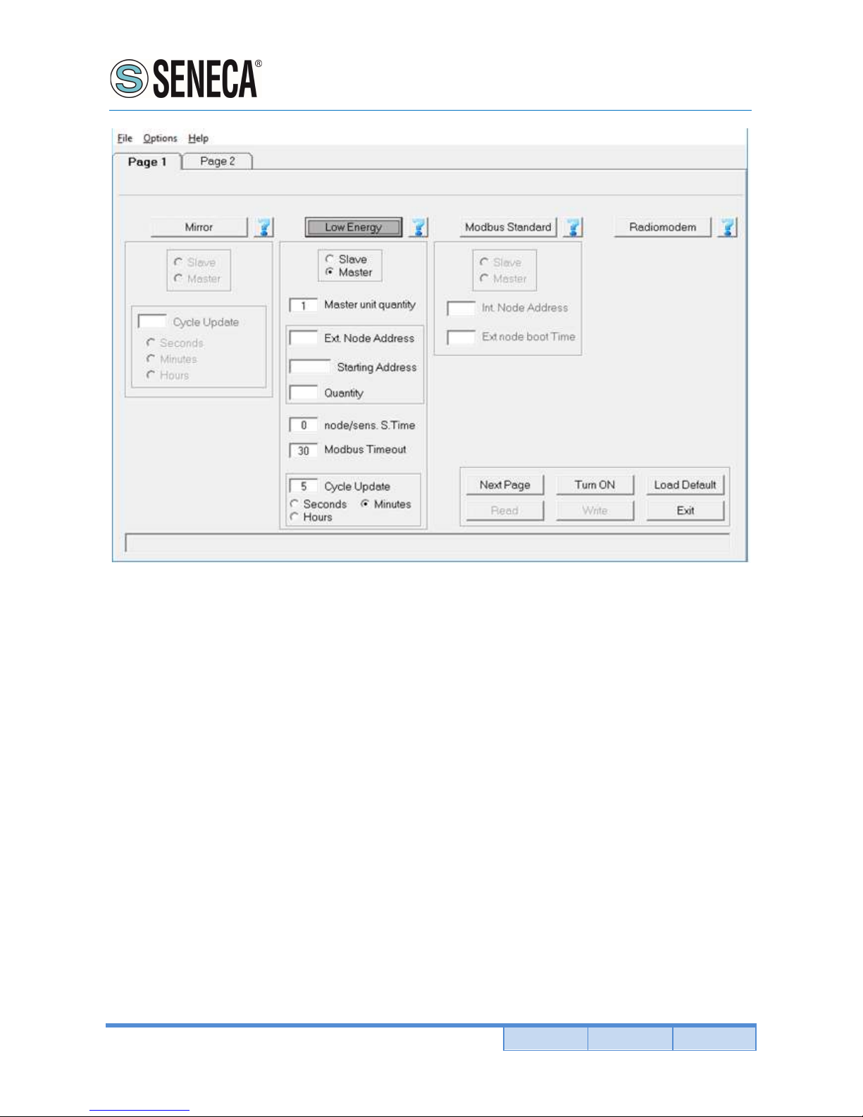
Slave / Master:
Allows you to select the functionality of the radiomodem between Master and Slave. The unit configured as a
Master uses the energy saving and transmits due to events. The unit configured as a slave is always active and
never takes the initiative of the transmission.
Master unit quantity:
Defines the number of the Master radiomodems present in the network. The allowed values range from 1 to 16.
Ext node address:
In this field the address of the external modbus node is set, which it must be identical to the address assigned
to the modbus node device.
Starting address:
In this field the address of the first register to be read from the external node is set.
Quantity:
In this field the quantity of registers to be read from the external node (max 96 registers) is set.
Node/sens S. Time:
This is the interval of time required to the external modbus node to become ready after the switch on. The
radiomodem provides power to the external Modbus node (18 Volt) only after a transmission trigger event. See
the related datasheet for sizing this variable.
Page 19
User Manual
RM169-1
Pag. 19 Doc. MI004760-E Rev. 0
www.seneca.it
ALL RIGHTS RESERVED. NO PART OF THIS PUBLICATION MAY
BE REPRODUCED WITHOUT PRIOR PERMISSION.
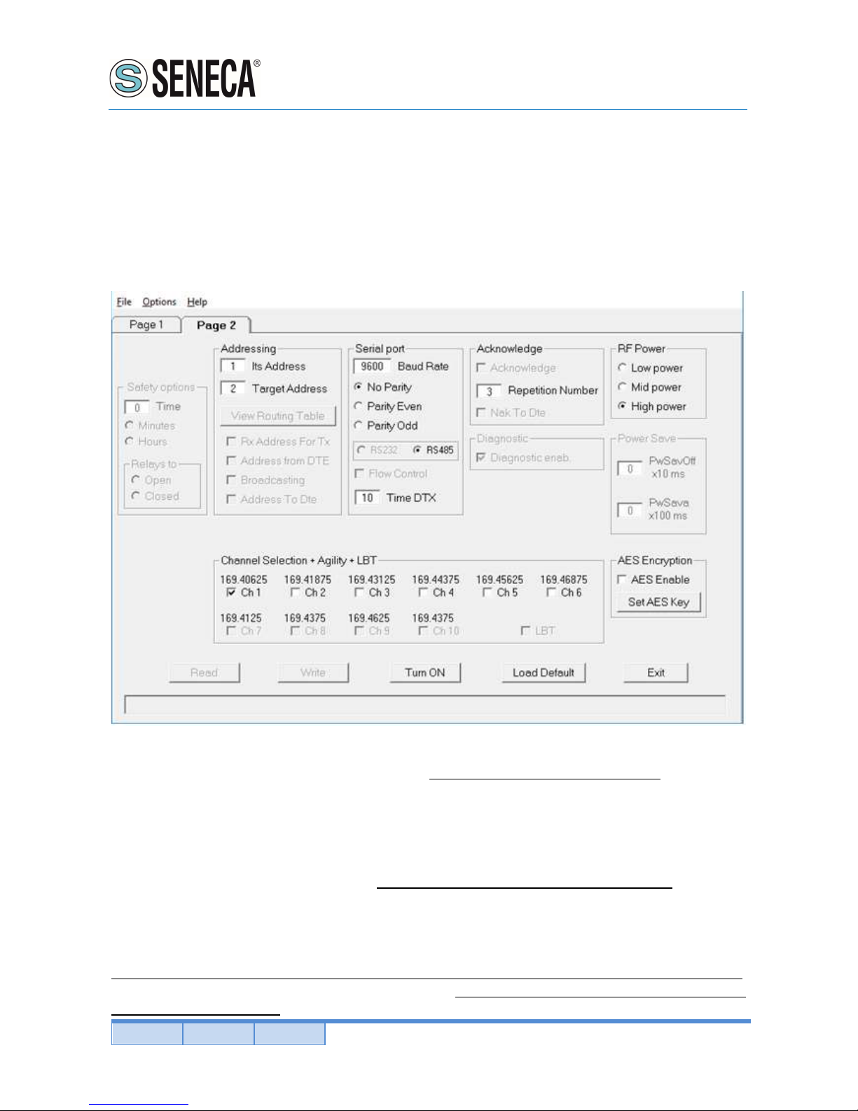
Modbus timeout:
Represents the time interval (in hundreds of milliseconds) within which the modbus answer on the packet sent
by the Master unit must be received.
Cycle Update:
In this field the time of the periodical transmission is set. The time base is selectable between seconds, minutes
or hours. The time range can vary from one second (minimum) to 255 hours (maximum). In this field you cannot
insert a value less than the time interval assigned to the field "External node boot time".
Its address:
Contains the value of the address of this radiomodem. Each unit must have a unique address. In the Master
device the maximum value of this field is dependent on the number of units in the network (parameter selected
in the field "Unit quantity").
Target address:
This field sets the value of the destination address. In the Master units, this field must contain the same address
used in the field "Its address" of the Slave unit. In the Slave units this field is not taken into account because the
mode "RX Address for TX" is used in the response packet.
When a device working as digipeater this value is uninfluenced.
System Code (double click of the mouse on "Target" or [Enter] key):
When the focus is on the Target field, pressing the "Enter" key on the keyboard or by double clicking the mouse,
a window opens in which you can enter the system code. The system code must be the same for all the
radiomodem in the network.
Page 20

User Manual
RM169-1
ALL RIGHTS RESERVED. NO PART OF THIS PUBLICATION MAY
BE REPRODUCED WITHOUT PRIOR PERMISSION.
www.seneca.it
Doc. MI004760-E Rev. 0 Pag. 20
Serial port:
In this frame (collection of options) the parameters choice of the serial line is performed. In the Master units,
these parameters configuration is referred to the data exchange between the radiomodem and the external
Modbus node. In the Slave unit, these parameters configuration is referred to the data exchange between the
radiomodem and the SCADA application. The format of the frame on the RS485 serial port uses one stop bit.
Baud rate:
This field is used to set the communication speed of the serial line. The legal values are: 1200, 2400, 4800,
9600, 19200, 38400, 57600 bps.
Parity:
By this selector it is possible to enable and choose the parity type on the serial line. It is possible to choose
between: None (parity disabled), parity Even, parity Odd.
Time DTX:
Defines the time between the stop of the data received from the serial port and the sending of the packet via
radio. In the "modus low energy" mode this parameter only affects the unit configured as a Slave. If you realize
that the data transmitted from the slave unit are incomplete, try to increase this time.
Repetition number:
It is active only in the devices configured as Master. In this field you can set the number of repetitions of a packet
when there is no answer.
RF Power:
Allows the choice between three different power levels: High, Medium, Low. If the value of the RSSI, present in
the diagnostic parameters sent to the SCADA software, is good (-70 dBm or better), and if the low power of the
Master unit is an important factor, it is advisable to choose a medium or low power level.
Channel selection + Agility + LBT:
In this box you choose the radio channel to be used. If you want to use the agility feature (transmission on the
less noisy channel among the active channels), you can select more than one radio channel. The maximum
number of active channels is dependent on the canalization setting. It is mandatory that in the same network
all the radiomodems use the same radio channels. In "Modbus Low Energy" mode the LBT function cannot
be activated.
AES Enable:
Enable or disable the AES-128 data encryption. In the transmitted packet, the encoding and decoding is done
on the payload only.
Set AES Key:
By pressing this button a window opens where the value of the 128-bit AES key is set. The user must insert 16
ascii character. The configurator displays an error message if, upon pressing the "OK" button, the string of the
AES key is incomplete (i.e. less than 16 characters are inserted).
Note: If the AES is used, all the radiomodems in the same network must use the same AES key. If the key
setting is not the same, the data transiting on the serial line are not interpretable by the connected SCADA
software.
Page 21

User Manual
RM169-1
Pag. 21 Doc. MI004760-E Rev. 0
www.seneca.it
ALL RIGHTS RESERVED. NO PART OF THIS PUBLICATION MAY
BE REPRODUCED WITHOUT PRIOR PERMISSION.
11.3. MODBUS OPERATING MODE
This mode of operation provides one Master unit (star centre) and one or more slave units. The Master unit must
be connected via the serial interface to a PC (or PLC) on which a SCADA application is running, which uses the
communication protocol Modbus RTU. The SCADA application is the heart of the system and has the task to
read and/or write the parameters of the different nodes of the network using the Modbus protocol. The Master
radiomodem, connected to the SCADA, uses the radio link to transmit the packets received from the serial line.
The required addressing is realised by the use of an internal routing table. To do this the Master radiomodem
evaluates the first byte of the received modbus packet, which, in the Modbus protocol, corresponds to the
address of the node which you want to communicate with. Each node address (1 to 254) may be associated
with an independent radio path.
All radio modems in the network (both Masters and Slaves) must be configured with an unique address (the "Its
address" field). The routing table is used to indicate the path of the packet radio, in this way, the packet arrives
to the target radiomodem directly or via all the interested digipeaters. In the routing table, the node address
number 255 is reserved for the broadcasting modbus packet. In this case, the Master radiomodem, when it
receives a packet with address zero (packet broadcasting type) from the SCADA application, uses the node
number 255 of the routing table to route properly the radio packet. The broadcasting mode cannot be
implemented if there is a radio modem unit that cannot communicate with all the other units of the network,
because in this case one or more units would not receive the broadcasting packet. This is the case of a network
geographically widespread in mountainous areas or where there are many obstacles.
The node addresses must be unique, in the same network can exist up to 254 nodes distributed according to
need among the slave units in the network. Avoid to assign the node address 255, which, as explained, is used
for the broadcasting packet. If, in a radiomodem unit, the internal peripherals are used, this radiomodem is seen
as a modbus node in the network. It has its own modbus address, through which it is possible to read and / or
write the internal peripherals of the radiomodem (digital inputs / outputs, pulse counter and analog inputs /
outputs).On each radiomdem up to 32 external Modbus nodes can be connected via the RS485 serial interface.
Each of these external nodes has its own modbus address, to be able to interrogate each node is necessary
that all the nodes belonging to the same slave units use the same routing, that is, the same sequence of
radiomodem addresses, which, in this case will be common to more node addresses (simply copy the addresses
of the radio path in every node address connected to the same radiomodem) given that the modbus packet must
pass through the same radiomodem.
At every slave radiomodem an external Modbus devices (I / O analog, digital or mixed) unit can be connected
via the RS485 interface. The maximum number external nodes is of 32 units. The maximum number of slave
radiomodes that may be present in a network is dependent on the number of modbus nodes connected to each
slave unit and also by the number of Slaves that use its internal peripherals: in this case each Slave radiomodem
has one modbus node address that is subtracted to the total of 254 modbus addresses available. Since the limit
is of 254 addresses, the sum between the radiomodem units (of which are used the internal peripherals) and
the external nodes connected cannot exceed this value. For example, if a network contains 25 slave radiomodes
used as modbus nodes (ie, if its internal peripherals are used), the maximum number of available addresses of
the external nodes are: 254-25 = 229; distributed on each slave radiomodem according to the requirements and
Page 22
User Manual
RM169-1
ALL RIGHTS RESERVED. NO PART OF THIS PUBLICATION MAY
BE REPRODUCED WITHOUT PRIOR PERMISSION.
www.seneca.it
Doc. MI004760-E Rev. 0 Pag. 22
respecting the maximum limit of 32 nodes for each slave unit.
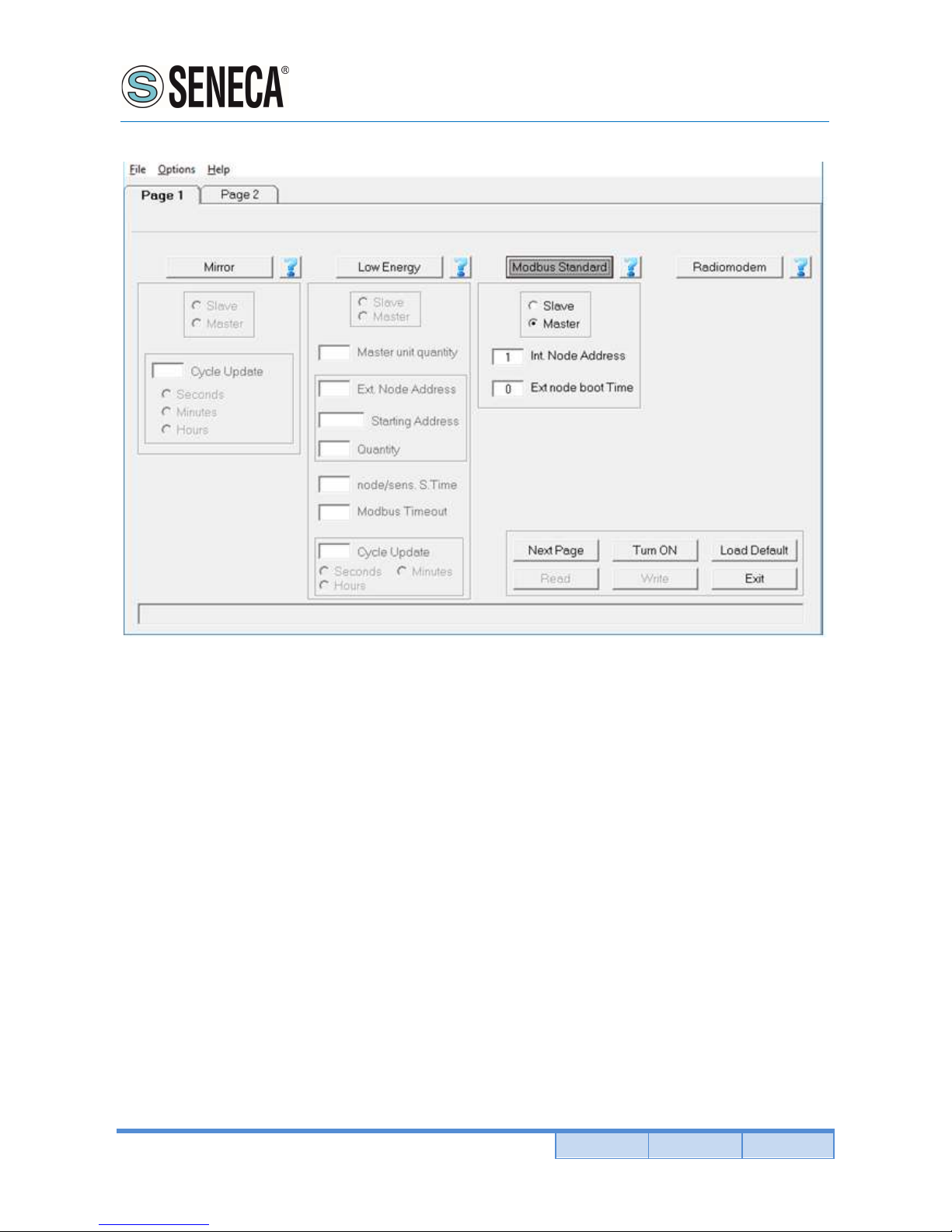
Slave / Master:
Allows you to select the functionality of the radiomodem between Master and Slave. The units configured as a
slave never takes the initiative of the transmission.
Internal node address:
It is the address of the modbus node related to the internal peripherals of the radiomodem. Set a non-zero value
if you want to use its internal peripherals.
Ext node boot time:
This field specifies the amount of time required for the external modbus nodes and/or for the external analog
sensors (connected to the analog inputs of the radiomodem) to be operationalThis field has a value in steps of
100 milliseconds. Set this parameter considering the node that takes longer to start-up.
Page 23
User Manual
RM169-1
Pag. 23 Doc. MI004760-E Rev. 0
www.seneca.it
ALL RIGHTS RESERVED. NO PART OF THIS PUBLICATION MAY
BE REPRODUCED WITHOUT PRIOR PERMISSION.
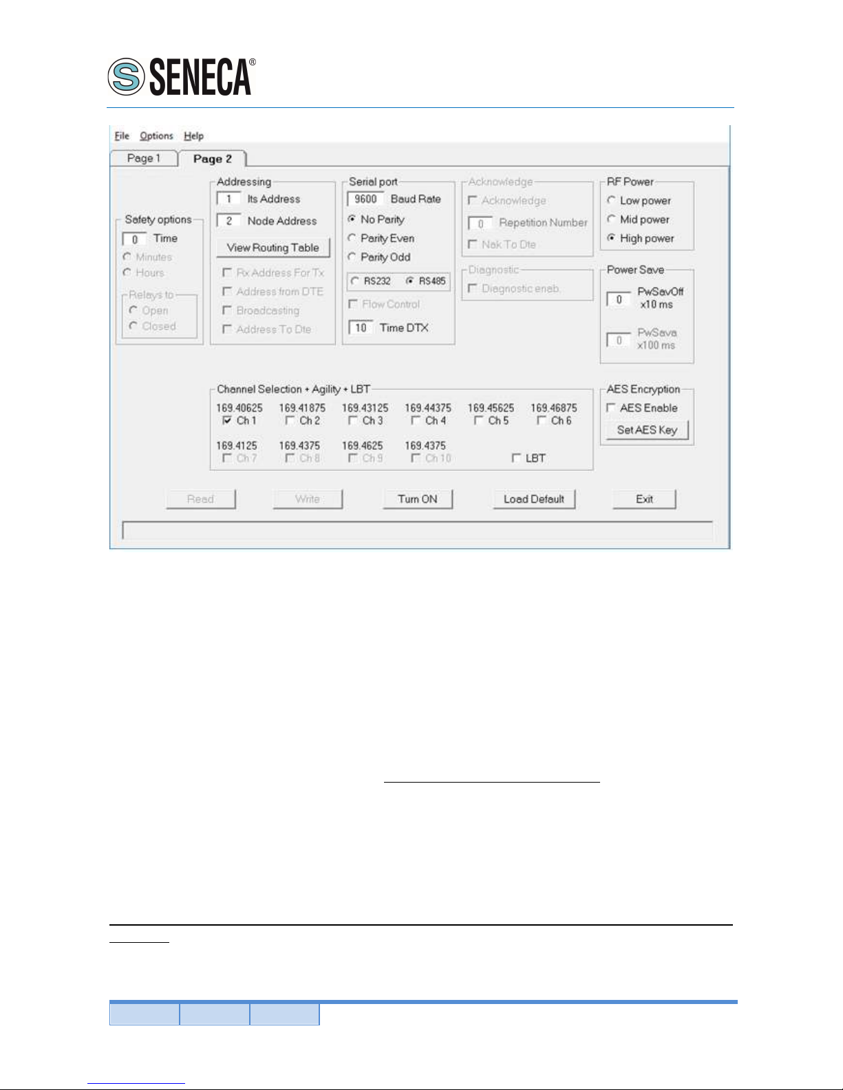
Safety options (frame):
Time: sets the value of the safety timer whose time base is selectable between minutes and hours. If the radio
doesn’t receive a valid packet within the selected time interval, the digital output (relay) is forced to a condition
chosen in the field "Relays to Open/Closed". To disable the functionality of the safety timer set the value of
"Time" to zero.
Minute: the value of "Time" is expressed in minutes.
Hours: the value of "Time" is expressed in hours.
Relays to Open: when the safety timer expires, the relay contact of digital output will be forced to open.
Relays to Closed: when the safety timer expires, the relay contact of digital outputs will be forced to closed.
Its address:
It is the value of the address of the radiomodem. Each unit must have a unique address. This constraint applies
both to the Slaves and to the Master radiomodems.
Node address (Master unit):
It is the value of the target modbus node. Each node address is associated with the sequence of addresses of
the radiomodems through the routing table.
Routing table (double click of the mouse on "Target" or [Enter] key):
When the focus is on the "Node address" field, pressing the "Enter" key on the keyboard or by double clicking
the mouse, a window opens in which you can enter the sequence of radiomodem addresses to associate to a
particular node address.
Page 24

User Manual
RM169-1
ALL RIGHTS RESERVED. NO PART OF THIS PUBLICATION MAY
BE REPRODUCED WITHOUT PRIOR PERMISSION.
www.seneca.it
Doc. MI004760-E Rev. 0 Pag. 24
System Code: it is the system code of the radiomodem. The purpose of this parameter is enabling the
communication only between those units that have the same system code value. This value must be the same
for all the radiomodem in the network.
Digipeaters: they are the addresses of the radiomodem, which have the task to retransmit the packet to a
subsequent radiomodem (another digipeater or the target unit). The purpose of these units is to extend the
coverage area of the radio network.
Target: it is the addressee station in the radio network.
View Routing Table:
Pressing this button with the mouse, a window opens where you can view all the values of the addresses of the
nodes and, for each one, its routing associations. Use the "Page Up", "Page Down" or the arrow keys to move
along the text. Press the key "Esc" or "Enter" or the spacebar on the keyboard to close this window.
Serial port:
In this frame (collection of options) the choice of the serial line parameters is performed. In the Master unit these
settings refer to the communication with the SCADA application, while in the Slave units these settings refer to
the communication with the external modbus node.
Baud rate:
This field is used to set the communication speed of the serial line. The legal values are: 1200, 2400, 4800,
9600, 19200, 38400, 57600 bps.
Parity:
By this selector it is possible to enable and choose the parity type on the serial line.
Time DTX:
Defines the time between the stop of the data received from the RS485 serial line and the transmission of the
radio packet. If the received packets are incomplete you must increase this time to mask any pauses between
the bytes of the packet sent from the SCADA application to the Master radiomodem. The steps are in
milliseconds.
RF Power:
Allows the choice between three different levels of transmission power: High, Medium, Low.
Power Save
PwSavOff:
When a number greater than zero is inserted, the Power Save feature is enabled. This field allows you to set
the value of the "OFF" time interval for the energy savings. The step is in tens of milliseconds.
PwSava:
When the power save is used, through this field you can set the time when the radiomodem remains operational
after an event (the reception of a radio packet) has temporarily awakened the unit. The step is in hundreds of
milliseconds.
Channel selection + Agility + LBT:
In this box you choose the radio channel to be used. If you want to use the agility feature (transmission on the
less noisy channel among the active channels), you can select more than one radio channel. The maximum
number of active channels is dependent on the canalization setting. It is mandatory that in the same network
all the radiomodems use the same radio channels.
Page 25

User Manual
RM169-1
Pag. 25 Doc. MI004760-E Rev. 0
www.seneca.it
ALL RIGHTS RESERVED. NO PART OF THIS PUBLICATION MAY
BE REPRODUCED WITHOUT PRIOR PERMISSION.
In the "modbus standard" mode you can enable the LBT feature: the radiomodem waits that the active channel
is free before transmitting the radio packet.
When the LBT function is active the device counts the seconds of data ON-AIR transmission in order to operate
according to EN300 220-1 standards that require to not exceed a transmission time of 100 seconds in a 1 hour
period. After 100 seconds the device stop the transmission and wait the 1 hour period before to allow a new
transmission.
AES Enable:
Enable or disable the AES-128 data encryption. In the transmitted packet, the encoding and decoding is done
on the payload only.
Set AES Key:
By pressing this button a window opens where the value of the 128-bit AES key is set. The user must insert 16
ascii characters. The configurator displays an error message if, upon pressing the "OK" button, the string of the
AES key is incomplete (i.e. less than 16 characters are inserted).
Note: If the AES is used, all the radiomodems in the same network must use the same AES key. If the key
setting is not the same, the data transiting on the serial line are not interpretable by the connected hardware.
Page 26
User Manual
RM169-1
ALL RIGHTS RESERVED. NO PART OF THIS PUBLICATION MAY
BE REPRODUCED WITHOUT PRIOR PERMISSION.
www.seneca.it
Doc. MI004760-E Rev. 0 Pag. 26
11.4. RADIOMODEM OPERATING MODE
This mode of operation is normally used for the exchange of data between different locations. In the same
network the presence of a master unit as well as of one or more slave units is expected. If the power save feature
is not used, each unit can receive data via the serial port RS485 (except during radio communications) up to a
maximum of 1024 bytes.
When the reception of the data is completed (i.e. when 1024 bytes are received or when the "Time DTX" timer
is expired), the radio modem send the packet to the target unit. It is possible to include in the radio path up to 8
digipeater to increase the coverage distance. If the Power Save feature is used, the logic behaviour is as follows:
the Master unit can always receive characters from the serial line (except during radio communications). The
slave units can receive characters from the serial line only during the time interval referred to as "PwSava" i.e.
the period in which a slave unit remains active after the reception of a radio packet.
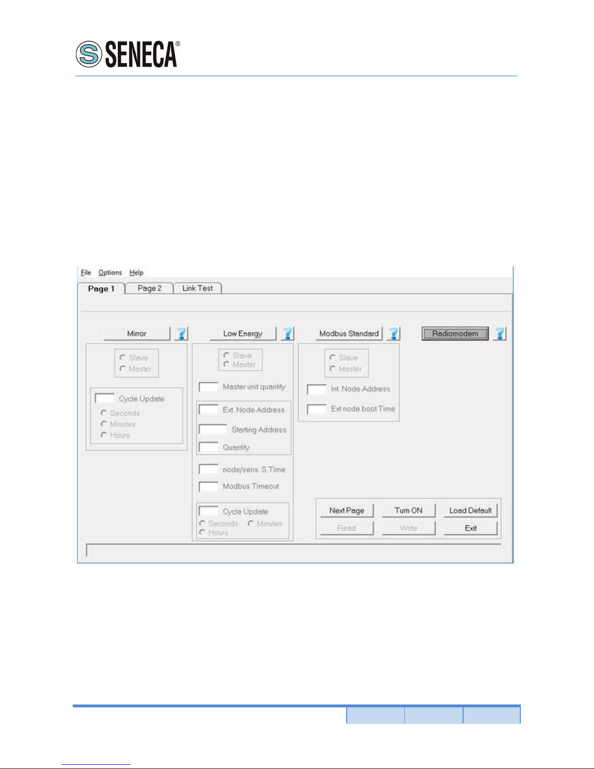
In the configurator, when the radiomodem mode is selected, an additional page called "Link Test" is available.
Refer to the relevant page of this manual for details.
Page 27
User Manual
RM169-1
Pag. 27 Doc. MI004760-E Rev. 0
www.seneca.it
ALL RIGHTS RESERVED. NO PART OF THIS PUBLICATION MAY
BE REPRODUCED WITHOUT PRIOR PERMISSION.
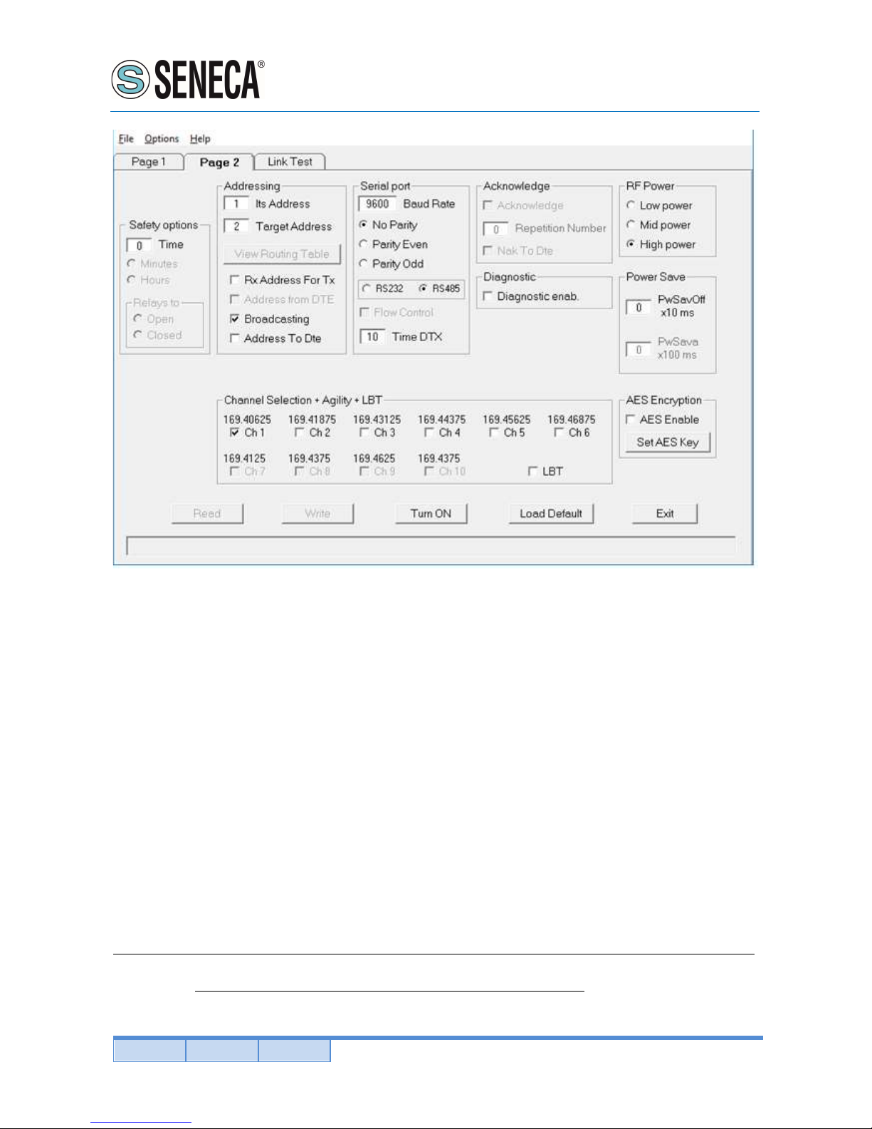
Safety options (frame):
Time: sets the value of the safety timer whose time base is selectable between minutes and hours. If the radio
doesn’t receive a valid packet within the selected time interval, the digital output (relay) is forced to a condition
chosen in the field "Relays to Open/Closed". To disable the functionality of the safety timer set the value of
"Time" to zero.
Minute: the value of "Time" is expressed in minutes.
Hours: the value of "Time" is expressed in hours.
Relays to Open: when the safety timer expires, the relay contact of digital output will be forced to open.
Relays to Closed: when the safety timer expires, the relay contact of digital outputs will be forced to closed.
Its address:
It is the value of the address of this radiomodem. It is advisable to configure each radiomodem with a unique
address.
Target address:
It is the address of the target radiomodem, the destination unit.
When a device working as digipeater this value is uninfluenced.
System Code & Digipeater address (double click of the mouse on "Target" or [Enter] key):
When the focus is on the Target field, pressing the "Enter" key on the keyboard or by double clicking the mouse,
a window opens in which you can enter the system code and the addresses of the digipeater path to include in
the radio link. The system code must be the same for all units in the network.
Page 28

User Manual
RM169-1
ALL RIGHTS RESERVED. NO PART OF THIS PUBLICATION MAY
BE REPRODUCED WITHOUT PRIOR PERMISSION.
www.seneca.it
Doc. MI004760-E Rev. 0 Pag. 28
Rx Address For Tx:
If enabled, the radiomodem stores the full address (digipeaters and target address) of the unit from which it
received the last packet and uses these addresses to send the data received from the DTE connected to it. This
function is available only if "Address from DTE" is inactive.
Address from DTE:
If active, the DTE must also provide the addressing for each transmitted packet. To do this, some bytes must be
added before of the data bytes. The bytes to add are in this order: one byte for the system code [1....255], one
byte-flag with the corresponding bits having the following scope: bit 0 (lsb) = Broadcasting ; bit1 = ECHO ; bit
2 = ACK request ; bit3 = Diagnostic. One Byte indicating the number of units [1 .... 9] which includes the target
and all the digipeaters used. From 0 to 8 bytes of digipeater addresses disposed in the exact sequence of use.
One Byte indicating the target address followed by the data bytes (from 1 to 1024). This function is available
only if "Rx Address For Tx" is inactive.
Broadcasting:
If enabled, the radiomodem transmits a special packet that will be received by all the radiomodem that have the
same System Code. This function is available only when the ACK is disabled.
Address to DTE:
If enabled, the data downloaded to the DTE will be preceded by the address of the sender. This feature allows
the identification of the source of the message.
Baud rate:
This field is used to set the communication speed of the serial line. The admitted values are: 1200, 2400, 4800,
9600, 19200, 38400, 57600 bps
Parity:
By this selector it is possible enable and choose the parity type on the serial line.
Time DTX:
Defines the time between the stop of the data received from the serial line and the transmission of the radio
packet. If the packets received are incomplete you must increase this time to mask any pauses between the
bytes of the packet sent from the DTE to the radiomodem. The steps are in milliseconds
Diagnostic enab:
When enabled, the radiomodem sends before of the data and, after the address of the sender if "Address to
DTE" is enabled, the diagnostic parameters in the following format:
remote rssi (16 bit signed integer, the first byte received is the least significant). The value is expressed in steps
of 0.0625 dbm.
remote Vbatt (unsigned 16-bit integer, the first received byte is the least significant). This value is not available,
overlook this value.
local rssi (16 bit signed integer, the first byte received is the least significant). The value is expressed in steps
of 0.0625 dbm.
ACK:
If enabled, the radiomodem that sent a packet waits for the acknowledge from the target radiomodem. If this
response it is not received within a fixed time, the last packet is re-sent many times as set in the "Repetition"
field. The function is available only if "Broadcasting" and "Address from DTE" are inactive.
Page 29

User Manual
RM169-1
Pag. 29 Doc. MI004760-E Rev. 0
www.seneca.it
ALL RIGHTS RESERVED. NO PART OF THIS PUBLICATION MAY
BE REPRODUCED WITHOUT PRIOR PERMISSION.
Repetition Number:
In this field you can define the number of repetitions of the packet if the acknowledge is not received. This
function is available only when the ACK is enabled.
Nak To DTE:
If enabled, the radio modem sends a NAK character (ASCII 21) to the DTE in the case where all repetition are
sent without receiving any acknowledge. This function is available only when the ACK is enabled.
RF Power:
Allows the choice between three different levels of power: High, Medium, Low.
PwSavOff:
Inserting in this field a number greater than 0, the power save feature is enabled. This is the value corresponding
to the off period of the energy savings cycles. The step is in the tens of milliseconds. The Master unit is always
active but uses this value to size the length of the preamble of the packets sent to a sleeping device (digipeater
or slave). If you intend to use the power save feature all units in the network must have the same "PwSavOff"
value. Note: If the Power Save feature is used, only the Master unit can always receive characters from the
serial line; the Slave can only do it during the PwSava period.
PwSava:
When the Power Save is used, by this field you can set the time interval in which the radio modem remains
operational (On) after it has been temporarily enabled by an event (i.e.: reception of a packet radio). This value
is in steps of hundreds milliseconds. This field is also used to differentiate the device between Master and Slave:
a value of 255 identifies the unit as Master and keeps it always On. The unit so configured is therefore not
affected by the ON-OFF cycles, but the packets are sent with a suitable (longer) preamble time in order to be
received by the slave devices that use the Power Save.
Channel selection + Agility + LBT:
In this box you choose the radio channel to be used. If you want to use the agility feature (transmission on the
less noisy channel between the active channels), you can select more than one radio channel. The maximum
number of active channels is dependent on the canalization setting. It is mandatory that in the same network
all the radiomodems use the same radio channels. It is possible to enable the LBT feature: the radio modem
waits for the channel to become free before proceeding with the transmission of the packet.
When the LBT function is active the device counts the seconds of data ON-AIR transmission in order to operate
according to EN300 220-1 standards that require to not exceed a transmission time of 100 seconds in a 1 hour
period. After 100 seconds the device stop the transmission and wait the 1 hour period before to allow a new
transmission.
AES Enable:
Enable or disable the AES-128 data encryption. In the transmitted packet, the encoding and decoding is done
on the payload only.
Set AES Key:
By pressing this button a window opens where the value of the 128-bit AES key is set. The user must insert 16
ascii characters. The configurator displays an error message if, upon pressing the "OK" button, the string of the
AES key is incomplete (i.e. less than 16 characters are inserted).
Note: If the AES is used, all the radiomodems in the same network must use the same AES key. If the key
setting is not the same, the data transiting on the serial line are not interpretable by the connected hardware.
Page 30
User Manual
RM169-1
ALL RIGHTS RESERVED. NO PART OF THIS PUBLICATION MAY
BE REPRODUCED WITHOUT PRIOR PERMISSION.
www.seneca.it
Doc. MI004760-E Rev. 0 Pag. 30
12. UTILITY
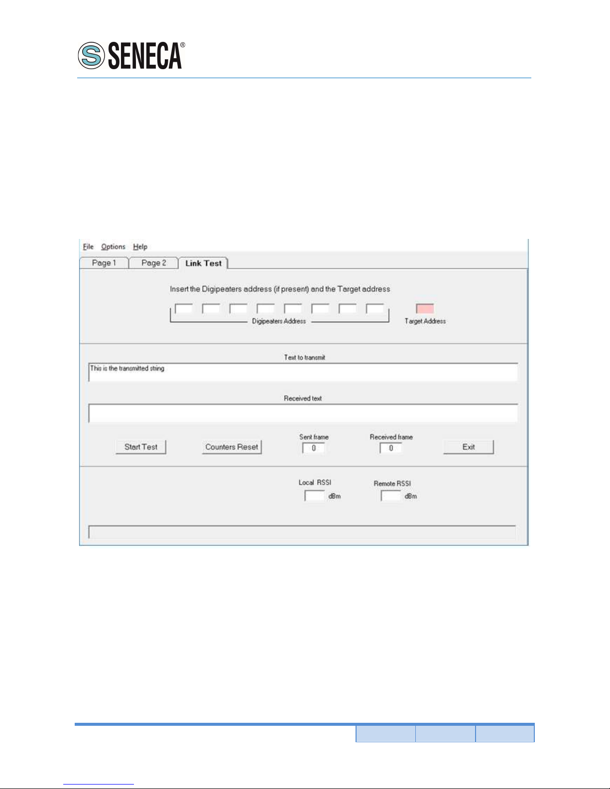
12.1. Link Test
The access to this page is only allowed if, on the first page of the configurator, the "radiomodem" modality is
chosen. On this page you can test the communication with the remote radiomodem, valuate the quality of the
radio signal and the level of the battery voltage on the selected units. This feature is only allowed in radiomodem
mode therefore the remote units reply to the link test packets only if they are configured in the same mode. This
functionality is available only in Configuration mode, enable the configuration mode as describe at configuration
paragraph of this manual.
When the use of the Link Test is finished it is necessary to switch off the radiomodem, then switch it on again.
This must be done in order to restore the normal operational functionality.
On the page 2 of the configuration program enter the same "system code" and the same power_save settings
as the one of the remote radiomodem you want make the link test with.
In order to avoid errors it is advisable to read the configuration from the local radiomodem via the Read button
(the radiomodem must be forced in configuration mode before read). In the "Link Test" page, enter the value of
the address of the target radiomodem and, if used, enter the values of the addresses of the digipeaters in the
exact order of use.
To start testing the reliability of the radio link, press the "Start Test" button: the string present in the "text to
transmit" text box is sent. In the "received text" box the received string is displayed; if no errors are found, this
string is equal to the sent string, vice versa an error message will be displayed. Each time a string is sent, the
"Sent frame" counter is incremented. The "Received frame" counter will be incremented only if the received
message is correct. Using the button "Counter Reset", you can reset the counter to zero. During the
Page 31

User Manual
RM169-1
Pag. 31 Doc. MI004760-E Rev. 0
www.seneca.it
ALL RIGHTS RESERVED. NO PART OF THIS PUBLICATION MAY
BE REPRODUCED WITHOUT PRIOR PERMISSION.
communications test the diagnostic parameters are also sent. These are: Local RSSI, Remote RSSI, Remote
VBatt. These values enable the assessment of the intensity of the radio signal received both from the remote
and local units. The RSSI fields are expressed in dBm and have a resolution of 0,0625 dbm. In another box the
value of the supply voltage of the remote radiomodem is displayed.
The RSSI provides a correct measurement in the range from -100 to -50 dBm. Values less than -100 dBm (for
example -105, -110 dBm) may create communication problems. The saturation of the measured RSSI restricts
the maximum value indicated approximately to -47 dBm ± 3dBm, signals of greater intensity return the same
indication.
Note: If, in the radio link, one or more digipeater units are used, the level of the RSSI is always referred to the
last received signal of the radio stations chain. Example: with four units present in the network (Master "A", first
digipeater "B" , second digipeater "C", slave "D") the RSSI read from the slave "D" is referred to the reception of
the digipeater "C", while the RSSI read from the master A is referred to the reception of the digipeater "B".
If you wish to use the readings of diagnostic (RSSI and VBatt) outside the configurator, the communication with
the radiomodem must use the serial data format "9600,N,8,1". The radiomodem send the following hex string:
System code (one byte), Flag options (one byte, value 0x08), quantity of addresses (one byte), digipeater
addresses (from 0 to 8 bytes), target address (one byte), one character (one byte).
Example: 0x01, 0x08, 0x01, 0x01, 0x55. This example uses the system code 1 with only one address: the target
(1). The last character (here 0x55) can be of any other value.
The radio modem returns a string consisting of six bytes: Remote RSSI (two bytes), VBatt remote (two bytes),
local RSSI (two bytes). For each pair, the first byte received is always the least significant byte.
The value of the RSSI is in the format 16-bit signed integer and has a resolution of 0.0625 dbm. Divide the RSSI
value by 16 to obtain the result with a step of 1 dbm.
The value of the battery voltage is in the format 16-bit unsigned integer. The formula used to derive the supply
voltage in volts is the following: read value * 0.0048828125.
The diagnostic request (bit 3 of the byte flag = set) excludes the normal data exchange.
Page 32
User Manual
RM169-1
ALL RIGHTS RESERVED. NO PART OF THIS PUBLICATION MAY
BE REPRODUCED WITHOUT PRIOR PERMISSION.
www.seneca.it
Doc. MI004760-E Rev. 0 Pag. 32
13. APPENDICE
13.1. MODBUS REGISTER
Read of digital input
Use Modbus command “Read discrete inputs” (0x02). The address are:
Digital input 1 = Address 0
Read of digital output
Use Modbus command “Read coils” (0x01). The address are:
Digital output 1 = Address 0
Read of radiomodem registers
Thanks to Modbus command “Read Input Registers” (0x04) it’s possible to read different Radiomodem
parameters as following:
Address 0: Digital input status (bit 0 = digital input 1)
Address 1: Battery voltage (mV)
Address 2: RSSI value of local unit (dbm, signed int16 format)
Address 3: RSSI value of remote unit (dbm, signed int16 format).
In order to read the register select the address node, set the starting address and the number of register to read
(max 8).
Write digital output
Use Modbus command “Write sigle coil” (0x05) or “Write multiple coils” (0x15). The address are:
Digital output 1 = Address 0
Digital output 2 = Address 1
13.2. MODBUS LOW ENERGY REGISTER
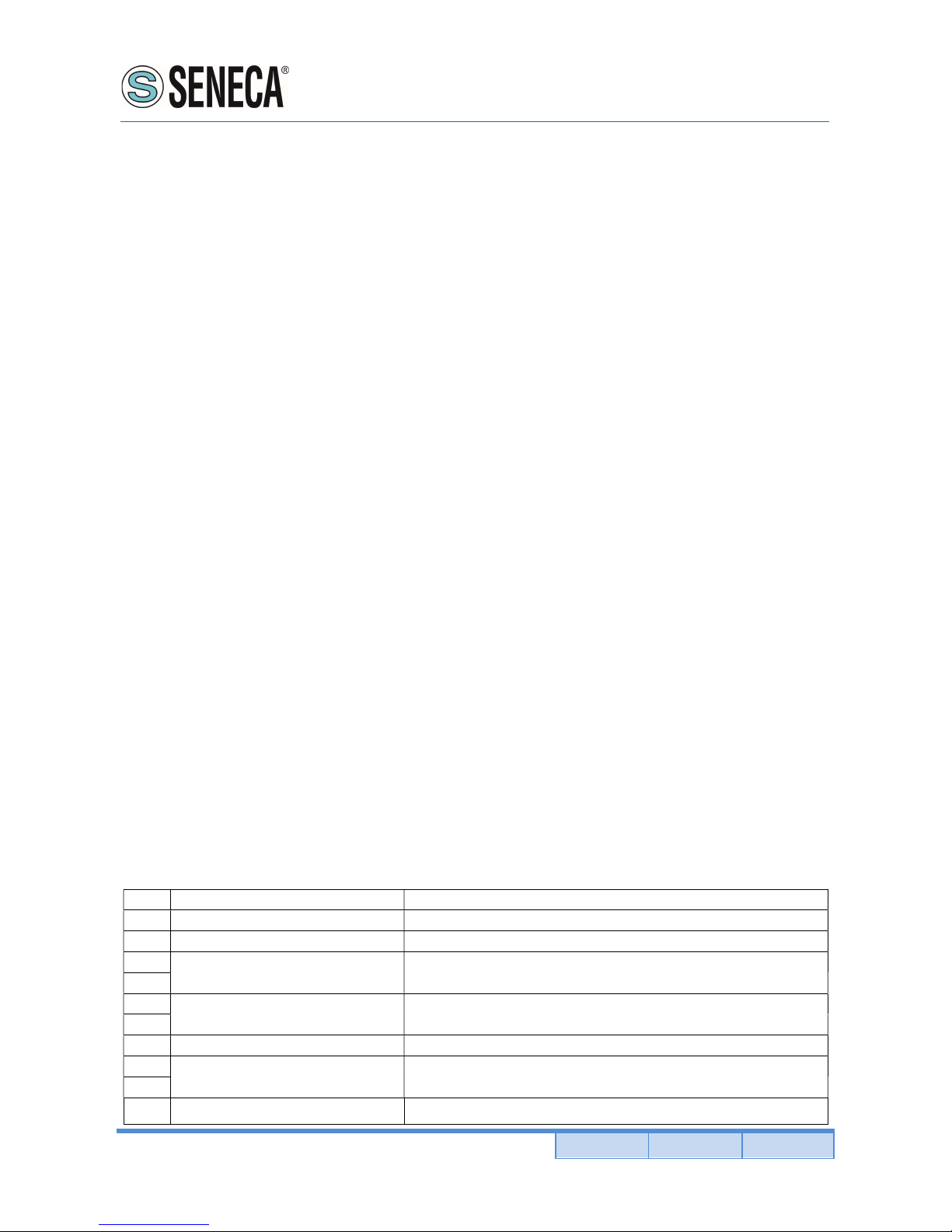
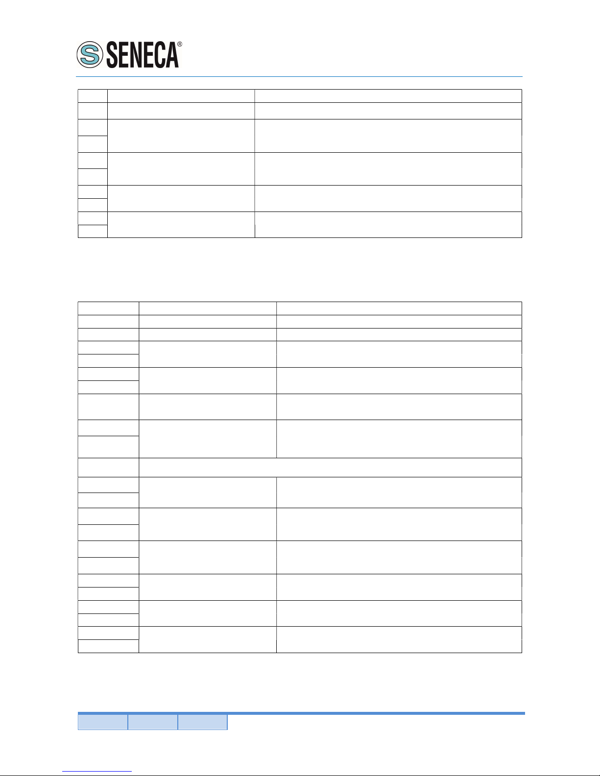
The Slave unit when receive the data from Master units write on SCADA register the data received starting from
register 100 as follows:
Master setup:
-External node not connect
-Digital input on
Byte
Description
Note
0 Slave Address
RM169
-
1 Address setted as Slave unit
1
Function Code
Preset Multiple Register 16
2
Data Address Address of first register, always 0064
3
4
Register quantity In this setup always 05
5
6 Number of bytes to follow
CRC not included, in this setup always 0A
7
Register 1- Digital input
Bit 0 = input 1
Value 1 refer to contact closed (active low)
8
9 Register 2 – Voltage battery Not available.
Page 33
User Manual
RM169-1
Pag. 33 Doc. MI004760-E Rev. 0
www.seneca.it
ALL RIGHTS RESERVED. NO PART OF THIS PUBLICATION MAY
BE REPRODUCED WITHOUT PRIOR PERMISSION.
Byte
Description
Note
10
11
Register 3 – RSSI Master unit
RSSI Value of Master unit related to previous data transmission
(dBm, signed int16)
12
13
Register 4 – RSSI Slave unit
RSSI Value of Slave unit related to previous data transmission
(dBm, signed int16)
14
15
Register 5 – Master Address Address of RM169-1 setted as Master unit (data sender)
16
17
CRC Cyclic Redundancy Check
18
Master setup:
-External node connected (register “n”)
-Digital input on
Byte Description
Note
0 Slave Address
RM169
-
1 Address setted as Slave unit
1 Function Code
Preset Multiple Register 16
2
Data Address Address of first register, always 0064
3 4
Register quantity Value in function of external node register quantity
5
6 Number of bytes to follow
CRC not included, value in function of external node
register quantity
7
Register “n”
External node register quantity “n” connected to PIN 14
and 16. This value must to setted also in “Ext Node
Address Quantity” tab.
8
After register’s node:
8+(n*2)
Register 1 – Digital input
Bit 0 = input 1
Value 1 refer to contact closed (active low)
8+(n*2)+1
8+(n*2)+2
Register 2 – Battery voltage Not available.
8+(n*2)+3
8+(n*
2)+4
Register 3 – RSSI Master unit
RSSI Value of Master unit related to previous data
transmission (dBm, signed int16)
8+(n*2)+5
8+(n*2)+6
Register 4 – RSSI Slave unit
RSSI Value of Slave unit related to previous data
transmission (dBm, signed int16)
8+(n*2)+7
8+(n*2)+8
Register 5 – Master address Address of RM169-1 setted as Master unit (data sender)
8+(n*2)+9
8+(n*2)+10
CRC Cyclic Redundancy Check
8+(n*2)+11
 Loading...