

Page 1

G.hn over Coax
Wi-Fi Gb Ethernet
Bridge
User’s Guide
V1.0
Page 2

INTRODUCTION
This G.hn to Wi-Fi Gb Ethernet bridge connects any
wireless and Ethernet devices to a high speed
connection of the coax network for Internet access.
This bridge brings you the newest Ethernet
compatible technology that uses the coaxial cable as
the network's physical wiring thereby eliminating the
need to install new wiring in a residential
environments. It is designed to operate on the coaxial
cable network.
This bridge allows you to connect PCs, STB and
wireless devices to Internet by simply plugging into
the existing coaxial F-Type connector.
Features
Plug & Play
Using existing coaxial TV cable to build a
network
Shares Internet access and streaming video
1 port connection compliant with 2Gbps G.hn
over Coax standard
2 Standard 100/1000BaseT Gigabit Ethernet ports
for connecting to Ethernet or PC or STB
IEEE 802.11 b/g/n/a/ac Wi-Fi MIMO Interface
QoS Priority Mapping Support
Configurable WiFi SSID and Key/Password
Statistics and Status Information Support
- 1 -
Page 3
HARDWARE INSTALLATION
b
Parts Names and Functions
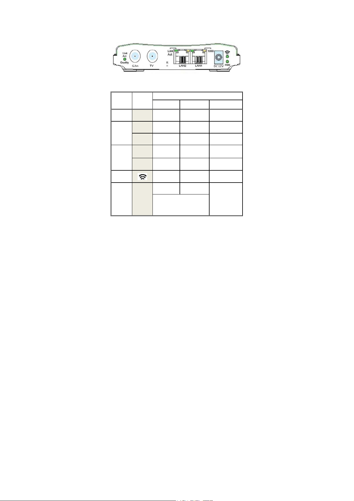
LED Indicators on the Rear Panel
Port
DC 12V
LAN1
LAN2
WiFi
G.hn
LED
PWR
Link
Act
1000
Link
Act
1000
Link
Act
Quality
ON Flashing OFF
Powered
DC12V
Link
1000Mbps N/A
Link
1000Mbps N/A 100Mbps
Link
Link
Green:High
Orange:Medium
Red:Low
Status
y
N/A Not powered
Receive or
Transmit
Receive or
Transmit
Receive or
Transmit
Receive or
Transmit
Disconnect or
Link fail
10Mbps or
100Mbps
Disconnect or
Link fail
Disconnect or
Link fail
Disconnect or
Link fail
- 2 -
Page 4
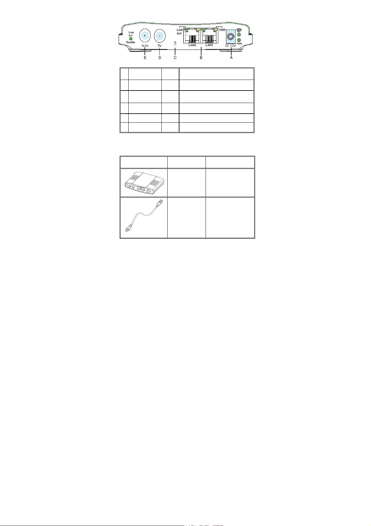
Ports on the Rear Panel
Port Name Type Functions
A
DC 12V
B
LAN1/LAN2
C
D
TV
E
G.hn
R
DC Connect to the power adapter plug.
Connect to PC or STB or other
RJ-45
Ethernet devics.
Factory Reset Button
F Connect to TV
F Connect to G.hn devices
Essential Hardwares
Items Included Description Purpose
G.hn to
WiFi GbE
Bridge
Coaxial
Cable
(F-Type/
RG-59U or
RG-6)
Main Unit
Connects from
G.hn port to
coax F-Type
connector on the
wall outlet.
- 3 -
Page 5

CAT5
Ethernet
cable
Connects from
LAN port to
Ethernet enabled
devices as PC
or STB
DC12V
Power
adapter
Connects from
Power port of
the main unit
into a wall outlet
Hardware Connections
1. Select a convenient location for the bridge near
the PC or Ethernet device to which it will be
connected. The bridge should be kept away from
excessive heat.
2. Using one coaxial cable to connect the G.hn
port to F-Type connector on the wall. Using
another coaxial cable to connect the other F-type
TV port to TV set (optional). Please make sure
the coaxial network is well grounded.
3. Connect the LAN1/LAN2 port to your Ethernet-
equipped device.
4. Connect the power adapter to the DC 12V port
into a wall outlet.
- 4 -
Page 6

The figure above shows the connection diagram of
coax network. Follow the same steps to connect
any Ethernet devices such as a STB or PC, and WiFi devices to the coax network.
Now you should have connected the LAN port,
G.hn port and the DC 12V port to the appropriate
devices or lines. LED will be as:
PWR ON
LAN Link/Act ON
(WiFi) ON
G.hn Link/Act ON (Green or Orange)
For more information on LEDs, see section entitled
LED Indicators on the Rear Panel"
"
- 5 -
Page 7

TROUBLESHOOTING
The bridge has been designed to be a reliable and
easy to use connection device. Please refer to the list
below to aid in troubleshooting.
The Power (green PWR) LED is off.
Make sure the power adapter is properly plugged
into a live electrical outlet.
The LAN(Ethernet) LED is off.
Make sure the connection to LAN port is secure.
The Ethernet device to which you are connected
should be powered on and properly configured.
The G.hn Link/Act/Quality LED is off or red
Make sure the connection to G.hn port is secure.
G.hn device to which you are connected should
be powered on and properly configured.
Make sure the quality of coaxial connector and
cable is good.
The
(WiFi) LED is off
Power off then power on the G.hn device.
Cannot connect to the Wi-Fi Bridge.
Make sure if the settings are correct.
The default SSID and the default WPA/WPA2
pre-shared key are on the label of device.
Restore the default factory reset by pressing R
button more than 3 sec (LED flashing), then
release the button while LED steady ON.
- 6 -
Page 8

SPECIFICATIONS
Standards
IEEE 802.3u 100BaseT Fast Ethernet
IEEE 802.3ab 1000BaseT Gigabit Ethernet
IEEE 802.11b/g/n/a/ac compliant
ITU-T G.9960/G.9961 G.hn over Coax
Data Rates
G.hn: 2Gbps (6-200MHz / Filter 216MHz)
Ethernet: 100 /1000 Mbps
Wi-Fi : 866M(5GHz)/300Mbps(2.4GHz) max
Transmission Range
G.hn : Up to 80dB attenuation
Ethernet: 100 meters maximum
Power Consumption
12V DC, 8 watt
Certifications
CE, FCC Part 15, VCCI
LEDs
Power
(WiFi) Link/Activity
Ethernet Link/Activity/Speed
G.hn Link/Activity/Quality
Connectors
Two F-Type connectors, one for connecting
with G.hn device, and one for TV Bypass
Two RJ-45 for 100/1000Mbps Ethernet
- 7 -
Page 9

Federal Communications Commission (FCC)
Statement
You are cautioned that changes or modifications not
expressly approved by the part responsible for
compliance could void the user’s authority to operate
the equipment.
This equipment has been tested and found to comply
with the limits for a Class B digital device, pursuant
to part 15 of the FCC rules. These limits are designed
to provide reasonable protection against harmful
interference in a residential installation. This
equipment generates, uses and can radiate radio
frequency energy and, if not installed and used in
accordance with the instructions, may cause harmful
interference to radio communications. However, there
is no guarantee that interference will not occur in a
particular installation. If this equipment does cause
harmful interference to radio or television reception,
which can be determined by turning the equipment
off and on, the user is encouraged to try to correct the
interference by one or more of the following
measures:
-Reorient or relocate the receiving antenna.
-Increase the separation between the equipment and
receiver.
-Connect the equipment into an outlet on a circuit
different from that to which the receiver is connected.
- 8 -
Page 10

-Consult the dealer or an experienced radio/TV
technician for help.
For product available in the USA/Canada market,
only channel 1~11 can be operated. Selection of other
channels is not possible.
Operations in the 5.15-5.25GHz band are restricted to
indoor usage only.
This device meets all the other requirements specified
in Part 15E, Section 15.407 of the FCC Rules.
This device complies with Part 15 of the FCC
Rules. Operation is subject to the following two
conditions:
1) this device may not cause harmful interference, and
2) this device must accept any interference received,
including interference that may cause undesired
operation of the device.
FCC RF Radiation Exposure Statement:
This equipment complies with FCC radiation
exposure limits set forth for an uncontrolled
environment. This equipment should be installed and
operated with minimum distance 20cm between the
radiator & your body. This transmitter must not be
- 9 -
Page 11

co-located or operating in conjunction with any other
antenna or transmitter.
- 10 -
 Loading...