

Page 1

Airtext Installation
Manual
Doc# 2016-25-05 Oct 30 2018, Rev F
Send Solutions
1765 Grassland Parkway, Suite D
Alpharetta, GA 30004
Page 2

Trademarks and Copyrights
©2015,2016,2017 The Bluetooth® word mark and logos are registered trademarks owned by Bluetooth
SIG, Inc. and any use of such marks by Send Solutions is under license. Other trademarks and trade
names are those of their respective owners.
Record of Revisions
1
Revision
IR
A
B April 2017 Added information for Airtext +
C May 2017 Added digital IO Info
D September 13, 2017 Clarified Doc Number
E Dec 7 2017 Fixed coax cable information chart on page 11. Updated
F Oct 30 2018 Improved accuracy of RF Cable loss information in coax
Revision Date
April 2016
August 2016 Part Number changes
Description
Initial Revision
Figure 1.
cable information chart and added some recommended
Iridium Antenna information on page 11.
Doc# 2016-25-05 Rev F Technical Support 678-208-3087 Ext #1 Airtext Installation Manual
Page 3
Current Revision Description
2
Section Number / Page Number
Pg. 11 Fixed coax cable RF Loss information chart and
Description of Change
added additional recommended Iridium Antenna
information.
Definition of Warnings, Cautions, and Notes
Warnings
Warnings indicate that immediate attention must be given to avoid potential equipment damage and
personal injury should the instructions be disregarded.
Cautions
Cautions indicate an alert to potential damage to the equipment if the procedural step is not directly
followed.
Doc# 2016-25-05 Rev F Technical Support 678-208-3087 Ext #1 Airtext Installation Manual
Page 4

3
Aviation Limited Warranty
Send Solutions warrants Airtext against material or manufacturing defects for a two-year period.
Warranty begins on date of installation.
If product support is required, please call our Technical Support team at 678-208-3087 to obtain
assistance. If the return of the unit to the factory is required, an RMA number will be issued at that time.
Send Solutions will, upon receipt of the failed hardware, remanufacture or replace the unit at our
discretion.
Send Solutions will pay Ground Shipping charges for warranted items. Charges for express shipment will
be the responsibility of the sender.
This warranty is not transferable. Any implied warranties expire at the expiration date of this warranty.
We shall not be liable for incidental or consequential damages.
This warranty does not cover a defect or failure that has resulted from improper or unreasonable
installation, use, or maintenance as determined by Send Solutions. This warranty is void if there is any
attempt to disassemble or open this product without factory authorization.
Any labor charges associated with the removal of product or related troubleshooting by a firm other than
Send Solutions or its designee will not be covered.
Doc# 2016-25-05 Rev F Technical Support 678-208-3087 Ext #1 Airtext Installation Manual
Page 5

4
Table of Contents
Contents
Trademarks and Copyrights .......................................................................................................................... 1
Current Revision Description ....................................................................................................................... 1
Definition of Warnings, Cautions, and Notes ............................................................................................... 2
List of Figures ........................................................................................................................................... 6
General Description ...................................................................................................................................... 6
Introduction ............................................................................................................................................... 6
Equipment Description ............................................................................................................................. 6
Technical Specifications ............................................................................................................................... 7
Physical Characteristics ............................................................................................................................ 7
Bluetooth Specifications ........................................................................................................................... 7
Certification .............................................................................................................................................. 8
Limitations ................................................................................................................................................ 8
Installation Overview .................................................................................................................................... 8
Introduction ............................................................................................................................................... 8
Unit Hardware Configurations .................................................................................................................. 8
Installation Material Required but Not Supplied ...................................................................................... 9
Special Tools Required ............................................................................................................................. 9
Cabling and Wiring ................................................................................................................................. 10
Coax Iridium Antenna Cable Considerations ......................................................................................... 11
Iridium Antenna Options ........................................................................................................................ 11
Sharing an Antenna ................................................................................................................................. 11
Mounting Requirements .......................................................................................................................... 12
HARDWARE INSTALLATION PROCEDURE ....................................................................................... 12
Wiring Harness Installation .................................................................................................................... 12
Doc# 2016-25-05 Rev F Technical Support 678-208-3087 Ext #1 Airtext Installation Manual
Page 6

5
Airtext Backshell Assembly and D-sub Connector ................................................................................ 13
Backshell Assembly Procedure ........................................................................................................... 13
Airtext Mounting .................................................................................................................................... 14
ROUTER CONFIGURATION ................................................................................................................... 15
List of configurable items ....................................................................................................................... 15
System Firmware Configuration. ............................................................................................................ 15
Digital IO configuration .......................................................................................................................... 15
ARINC Configuration ............................................................................................................................. 16
Standard ARINC-429 labels: .................................................................................................................. 17
POST-INSTALLATION CHECKOUT ...................................................................................................... 17
Mounting, Wiring, and Power Checks ................................................................................................ 17
Bluetooth Texting Setup ......................................................................................................................... 18
First time use. .......................................................................................................................................... 19
Send your first Text. ............................................................................................................................... 19
Bluetooth Voice Setup (Airtext+ only) ................................................................................................... 20
Make your first Voice call .................................................................................................................. 20
Optional Configuration ....................................................................................................................... 20
Testing Optional features ........................................................................................................................ 21
Software Updates .................................................................................................................................... 22
CONTINUED AIRWORTHINESS ............................................................................................................ 22
CONNECTOR PINOUT INFORMATION ................................................................................................ 23
TROUBLESHOOTING .............................................................................................................................. 24
Initial Installation Troubleshooting. ........................................................................................................ 24
If service has slowly degraded over time. ............................................................................................... 26
If Service Suddenly Stopped Working.................................................................................................... 26
PED (Personal Electronics Device) APP Problems ................................................................................ 26
Compatible PED (Personal Electronics Device) ..................................................................................... 27
Wired Data Problems .............................................................................................................................. 27
Voice Problems ....................................................................................................................................... 27
What more can be done? ......................................................................................................................... 28
Doc# 2016-25-05 Rev F Technical Support 678-208-3087 Ext #1 Airtext Installation Manual
Page 7

6
Airtext - Iridium Antenna Interconnect .............................................................................................. 32
Appendix A: Airtext router Firmware Updates .......................................................................................... 33
Update Airtext router using ANDROID phone or Tablet ....................................................................... 33
List of Figures
Figure 1– Outline and Installation Drawing
Figure 2 - Interconnect Drawing
Figure 3 - Sample Wiring Diagram
Figure 4 - Sample Interior Power Circuitry Diagram
General Description
Introduction
This manual is intended to provide physical, mechanical, and electrical information for use in the
planning and design of an Airtext hardware unit into an aircraft. It is not a substitute for an approved
airframe-specific maintenance manual, installation design drawing, or complete installation data package.
Attempting to install equipment by reference to this manual alone, and without first planning or designing
an installation specific to your aircraft, is not recommended. The content of this manual assumes use by
competent and qualified avionics engineering personnel and/or avionics installation specialists using
standard aviation maintenance practices in accordance with Title 14 of the Code of Federal Regulations
and other relevant accepted practices. It is not intended for use by individuals who lack the competencies
set forth above.
Equipment Description
Airtext solves the problem of staying connected electronically to business, friends, and family without the
high cost of a traditional internet option. Airtext allows up to 16 passengers the ability to send and receive
SMS messages anywhere in the world. Using the Iridium satellite network, we have designed a product
that allows connectivity through your cell phone while on the airplane.
Doc# 2016-25-05 Rev F Technical Support 678-208-3087 Ext #1 Airtext Installation Manual
Page 8
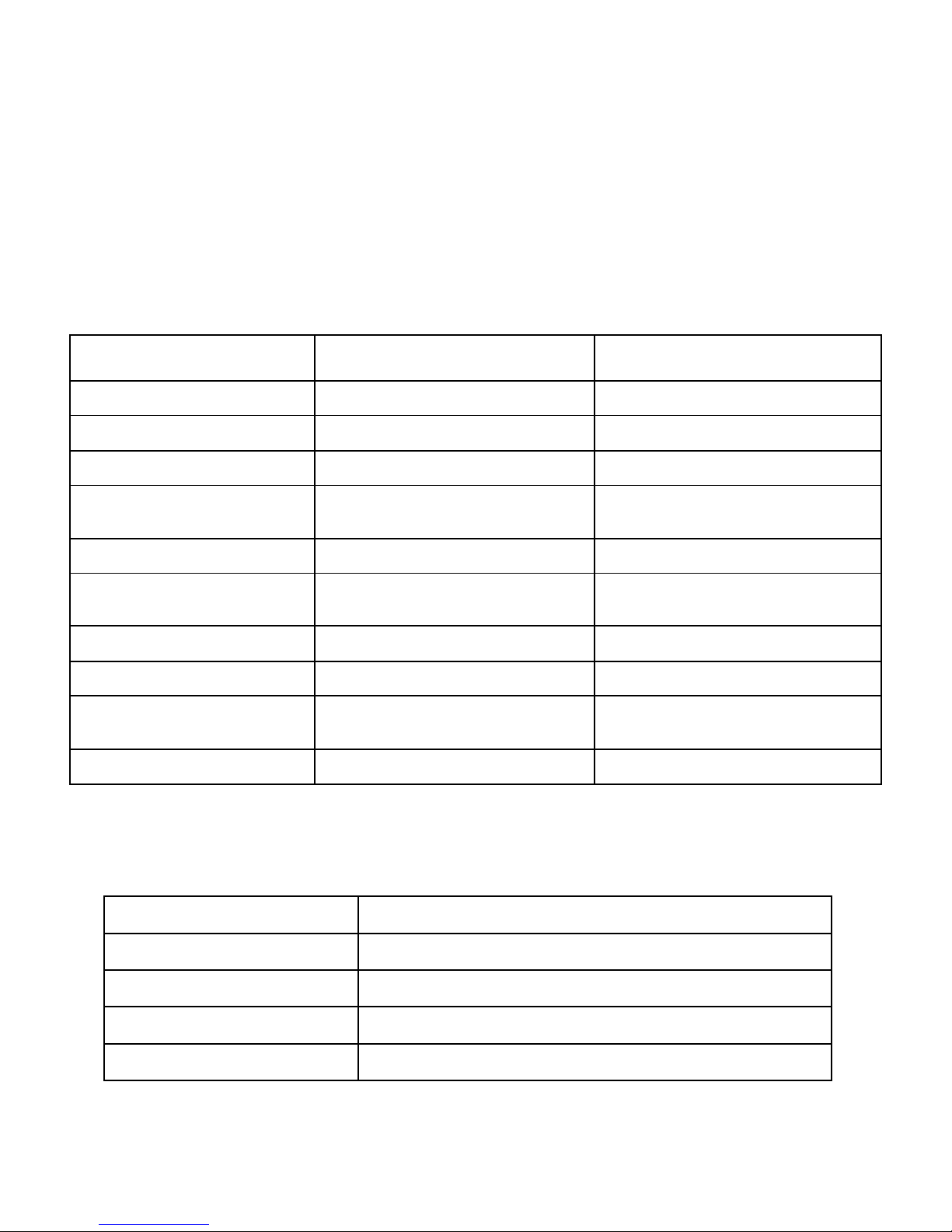
Technical Specifications
Physical Characteristics
Specification Airtext Airtext +
7
Operating Temperature Airtext
Storage Temperature
Operating Voltage
Operating Current .276 Amps @ 12 Volts, and .12 Amps
Inrush Current
Size (Without antennas &
cables)
Weight Airtext
Materials
DO-160 Testing Section 16 Category Z, Section 21
Antenna Connector
-40C to +75C (At less than 75% RH) -40C to +65C (At less than 75% RH)
-40C to +85C (At less than 95% RH) -40C to +85C (At less than 95% RH)
+11 VDC to +32 VDC
@ 28 Volts
10 Amps for 8uS @ 28 Volts
7.5” X 4.6” X 1.4” 7.5” X 4.6” X 1.4”
1 lb. 1 oz.
Black Anodized Aluminum
Category M
TNC, Female Standard
Bluetooth Specifications
+11 VDC to +32 VDC
.276 Amps @ 12 Volts, and .12 Amps
@ 28 Volts
10 Amps for 8uS @ 28 Volts
1 lb. 2 oz.
Black Anodized Aluminum
Section 16 Category Z, Section 21
Category M
TNC, Female Standard
Characteristics
Bluetooth Version
Bluetooth Class
Maximum Transmitter Power
Effective unimpeded range
Doc# 2016-25-05 Rev F Technical Support 678-208-3087 Ext #1 Airtext Installation Manual
Specification
4.1
2.0
4 dBm (2.5 mW)
33 feet (10 m)
Page 9

8
Certification
FAA STC Number: ST04269AT with PMA approval.
This device complies with DO-178B design assurance Level E.
Limitations
Operation
Airtext wireless system has been tested for interference. Its operation must not interfere with the proper
operation of any required aircraft equipment or systems. The installation requires the installer to verify
that there is no interference using the post-installation check-out procedure.
Installation
For preservation of essential equipment in aircraft with multiple power busses, Airtext should be powered
from a non-essential, shedable bus.
Installation Overview
Introduction
This section provides the equipment information for installing Airtext and related optional accessories.
Installation of Airtext should follow the data detailed in this manual. Cabling is typically fabricated by the
installing agency to fit each particular aircraft. Always follow acceptable avionics installation practices
per advisory circulars AC 43.13-1B and AC 43.13-2B or later FAA approved revisions.
Unit Hardware Configurations
Airtext is available with the following part numbers.
Model
Airtext 15G25 16 Text users Airtext Install
Airtext + 15G25-2 16 Text users and Voice Airtext Install
Part P/N
Description
Installation Kit
Airtext + 15G25-3 64 Text users Airtext Install
Doc# 2016-25-05 Rev F Technical Support 678-208-3087 Ext #1 Airtext Installation Manual
Page 10
9
Installation Material Required but Not Supplied
Airtext units are intended for use with standard aviation accessories. The following items are required for
installation but not supplied:
1. Airtext™ Application
2. Wire (MIL-W-22759/20 or equivalent)
NOTE
Extra care must be taken to adequately support and protect the wiring due to its thin insulation.
3. Shielded wire (MIL-C-27500 cable utilizing M22759/20 wire (TG) or ETFE jacket (14), or
equivalent)
4. Aircraft hardware for installation, including #6 screws, nuts / nut plates, washers, and rivets
5. Bonding strap hardware
NOTE
In order to reduce HIRF susceptibility for LRUs interfaced to Airtext, it is recommended to include a
bonding strap on Airtext router. This bonding strap is not required per Airtext STC. However, certain
STCs may require it. If applicable, please reference your installation’s STC documentation for further
installation requirements.
6. Push/pull (manually resettable) circuit breaker
7. Tie wraps or lacing cord
8. Ring terminals (MS25036 or equivalent)
9. Shield terminators (MIL-S-83519 or equivalent)
10. Silicon fusion tape (Send Solutions P/N 700-00022-100 or equivalent)
11. Compatible portable electronic device (PED)
Special Tools Required
Pin Contact Numbers
Wire Gauge DB 25 – pin Contacts
Send Solutions P/N 460-00005-000
Military P/N M39029/7-357
20-24 AWG
Doc# 2016-25-05 Rev F Technical Support 678-208-3087 Ext #1 Airtext Installation Manual
Page 11
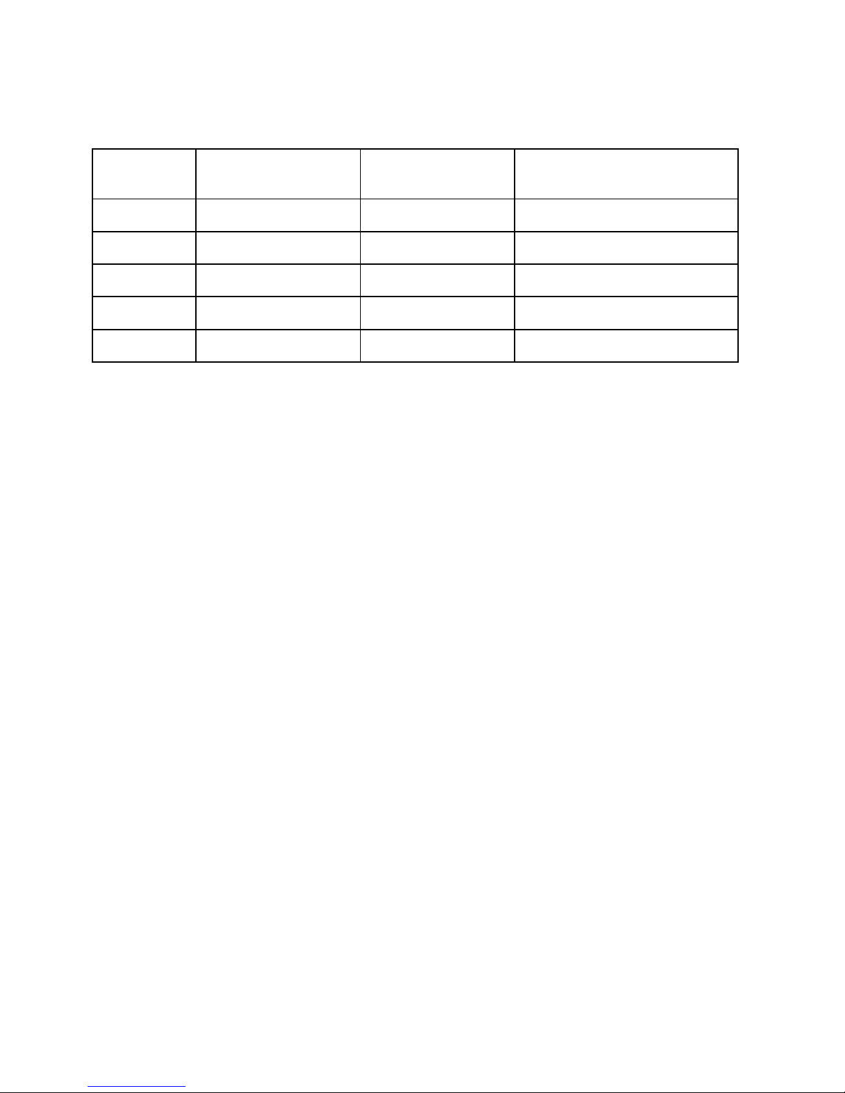
Recommended Crimp Tools
10
Wire Gauge Hand Crimping Tool 20-24 AWG
Positioner
Military P/N M22520/2-01 M22520/2-09 M81969/1-04
Positronic 9507 9502-4 M81969/1-04
Amp 601966-1 601966-6 91067-1
Daniels AFM8 K42 DAK95-22MB/ DRK95-22MB
Astro 615717 615725 M81969/1-04
NOTE
Non-Send Solutions part numbers shown are not maintained by Send Solutions and are subject to change
without notice.
Insertion Extraction Tool
Cabling and Wiring
Wiring should be installed in accordance with AC 43.13-1B Chapter 11. When wire separation cannot be
achieved, the following issues should be addressed:
• The cable harness should not be located near flight control cables, high electrical capacity lines, or fuel
lines.
• The cable harness should be located in a protected area of the aircraft.
• Do not route cable near high-energy sources.
See the interconnection diagrams in Figure 2 for the appropriate wiring. Once the cable assemblies have
been made, attach the cable connector. Route the wiring bundle as appropriate. Avoid sharp bends.
For Airtext, use 22 AWG or 20 AWG wire for all connections including power/ground.
CAUTION
Check wiring connections for errors before connecting the 25-pin D-sub to Airtext. Incorrect wiring could
cause component damage.
Doc# 2016-25-05 Rev F Technical Support 678-208-3087 Ext #1 Airtext Installation Manual
Page 12

11
Coax Iridium Antenna Cable Considerations
RF Path Signal loss is determined by the coax cable type, its length, and condition. Minimize cable
length to preserve signal strength. The total implementation loss for an antenna, connectors, cable,
disconnects, lightning arrestor, and any other RF component between the Airtext router and the antenna
should not exceed 3dB.
Coax Cable Type Approx. Signal
Loss per 100 ft.
PIC S86208 (RG-142) 18.04 dB .13 .65 inch
Emteq PFLX195-500 (RG-142) 14 dB .20 .5 inch
PIC S33141 (RG-393) 8.63 dB .27 1.4 inch
PIC S55122 (RG-393) 6.5 dB .31 1.55 inch
Emteq PFLX240-500 11 dB .242 .75 inch
RG-8A (non-aviation) 8 dB .405 1 inch
Cable
Diameter inch
Minimum Bend
Radius
Example cable: Pic Wire and Cable Company; www.picwire.com
Part Number: 34480-4300-04. 10' CABLE ASSEMBLY W/ S33141 CABLE & 190308 TNC Male
Straight connector & 190309 TNC Male Right Angle Connector.
Iridium Antenna Options
Antcom, Cobham/Comant, Sensor Systems… are some of the manufacturers of Iridium antennas. Newer
models of Iridium antennas such as Sensor Systems S67-1575-410 support higher transmit power
capability that may be needed for Iridium Certus℠ Broadband, available starting in 2019 as Iridium’s
next-generation satellites come online. Dual and Quad antennas are available to permit replacing a single
channel GPS antenna or single channel Iridium antenna with a GPS/Iridium or GPS/multiple iridium that
are designed to use existing mounting hole pattern and existing doubler.
Sharing an Antenna
If there is an existing Iridium antenna on the airplane that is occasionally utilized for a phone it may be
possible to share the antenna with Airtext. This is accomplished with a relay and switch to share the use
of the antenna. The switch should be marked Voice (for phone use) and Data (for Airtext use). For the
STC a Pasternak PE7147 Relay was used. Any similar coax relay would be sufficient.
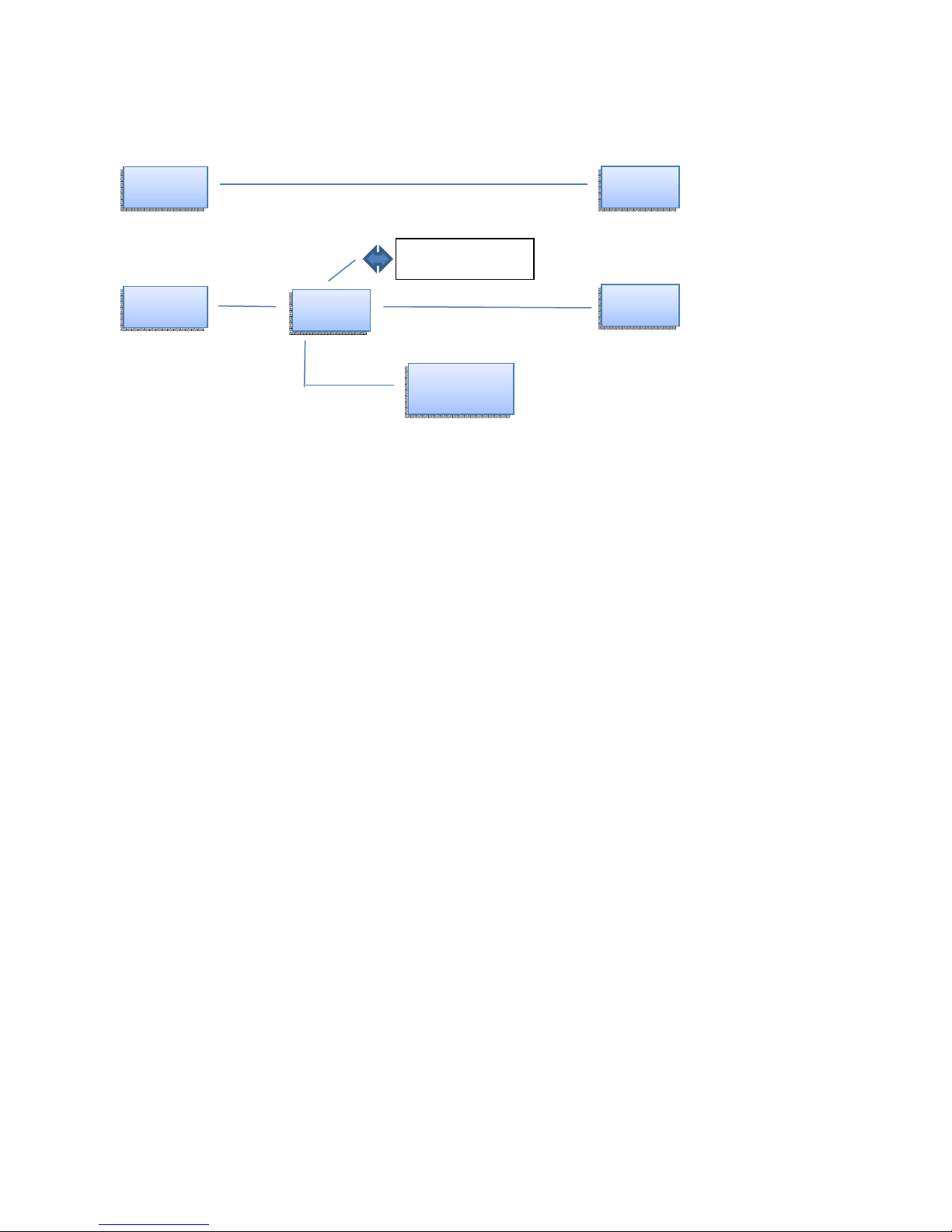
If antenna sharing is not required, then interface option 1 can be used. If the existing Iridium antenna is to
be shared with the phone, then interface option 2 may be used. Components are: Airtext, an A/B switch, a
coaxial relay, and the Iridium phone antenna. The second interface would require installing an Iridium
antenna. Components are: Airtext and the Iridium antenna.
Doc# 2016-25-05 Rev F Technical Support 678-208-3087 Ext #1 Airtext Installation Manual
Page 13
Interface Option 1
Airtext
Airtext
Antenna
Antenna
Interface Option 2
12
Voice/ Data Switch
Relay
Old Phone
Mounting Requirements
Airtext should be mounted in a pressurized and heated location. To achieve optimal Bluetooth reception,
mount Airtext as close as possible to the cabin. The optimum location is in a side wall near the center of
the cabin. Alternate Bluetooth antennas are available if the Airtext router must be mounted beneath a
metal or carbon fiber floorboard, or in a cabinet or behind a partition made from metal honeycomb where
Bluetooth transmissions may be degraded. A multitude of sizes and shape antennas and various length
antenna cables are available. Select one that is designed to work with Bluetooth radios. These antennas
and their extension cables replace the stub antennas supplied by Send Solutions. Some models may be
purchased through Send Solutions.
Cooling air is not required except in locations where the specified maximum ambient operating
temperature may be exceeded.
HARDWARE INSTALLATION PROCEDURE
This section provides hardware equipment information for installing Airtext. For interconnects with
interfaced equipment, see Figure 2.
Wiring Harness Installation
Allow adequate space for installation of cables and connectors. Observe minimum bend radius for the
coax cable. All electrical connections are made through a 25-pin D-sub connector provided by Send
Solutions. Construct the wiring harness according to the information contained in this and the following
sections. Cable lengths will vary depending upon installation.
1. Strip all wires going to the D-sub connectors 0.17".
Doc# 2016-25-05 Rev F Technical Support 678-208-3087 Ext #1 Airtext Installation Manual
Page 14

2. Insert the wire into the pin and crimp with one of the recommended (or equivalent) crimping tools.
3. Insert the pin into the D-sub connector housing locations as specified by the interconnect drawing.
4. Verify the pin is properly engaged into the connector by gently tugging on the wire.
5. Route and secure the cable run from Airtext to the other units away from sources of electrical noise.
See cable and wiring above for the electrical characteristics of all input and output signals. Required
connectors and associated hardware are supplied with the connector kit. See Figure 3 for sample
interconnect wiring diagrams.
Airtext Backshell Assembly and D-sub Connector
Description Send Solutions P/N
Qty 2 Spring Latch Plate ITT Cannon D110278 460-00002-000
Qty 1 Backshell, 25 Pin ITT Cannon DB11533922 460-00003-025
Qty 1 Conn, HD D-Sub, 25 Pin TE Connectivity 1757820-3 330-00626-15
13
Backshell Assembly Procedure
The parts for the connector and backshell assembly for Airtext installations are listed above.
Connector and Backshell should be assembled in such a way that the shield (if used) of the cable is
attached to the ground return or airframe at one end only. If the shield is connected to the connector
backshell at the Airtext end, then it should not be connected to the airframe at the far termination or mid
disconnects.
Shielded Cable Preparation
1. At the end of the shielded cable, strip back a 2.5" maximum length of the jacket to expose the braid.
Remove this exposed braid. Carefully score the jacket 1/4" to 5/16" from the end and remove the jacket to
leave the braid exposed.
NOTE
Solder sleeves with pre-installed shield drains may be used instead of separate shield terminators and
individual wires. Using solder sleeves with pre-installed lead effectively takes the place of step 7.
2. Connect a 22 AWG wire to the exposed shield of the prepared cable assembly. AC 43.13 may be a
helpful reference for termination techniques.
Doc# 2016-25-05 Rev F Technical Support 678-208-3087 Ext #1 Airtext Installation Manual
Page 15

14
NOTE
Solder Sleeves with pre-installed lead: A preferred solder sleeve is the Raychem S02 Series with the
thermochromic temperature indicator. These solder sleeves come with a pre-installed lead. For detailed
instructions on product use, refer to Raychem installation procedure.
3. Slide a shield terminator onto the prepared cable assembly and connect the wire to the shield using a
heat gun approved for use with solder sleeves. The chosen size of solder sleeve must accommodate both
the number of conductors present in the cable and the wire to be attached.
NOTE
Each tapped hole on the shield block may accommodate only two ring terminals. It is preferred that a
maximum of two wires be terminated per ring terminal. Two wires per ring terminal will necessitate the
use of a ring terminal, #8, insulated, 14-16 AWG (MS25036-153). If only a single wire is left, or if only a
single wire is needed for this connector a ring terminal, #8, insulated, 18-22 AWG (MS25036-149) can
accommodate this single wire. If more wires exist for the connector than two per ring terminal, it is
permissible to terminate three wires per ring terminal.
5. Terminate the ring terminals to the shield block by placing items on the pan head screw in the
following order: split washer, flat washer, first ring terminal, second ring terminal if needed, before
finally inserting the screw into the tapped holes on the shield block.
6. Wrap the cable bundle with silicone fusion tape (P/N 700-00022-100 or a similar version) at the point
where the backshell strain relief and cast housing will contact the cable bundle.
7. Place the smooth side of the backshell strain relief across the cable bundle and secure using the two
screws.
WARNING
Placing the grooved side of the strain relief across the cable bundle may damage wires.
NOTE
Ensure the Airtext router’s serial number and Iridium Radio’s IMEI number, located on the bottom of the
unit is noted and saved in a convenient location for future reference.
Airtext Mounting
The Airtext transceiver is mounted using four #8 pan head screws (MS35206, AN526, or equivalent) onto
a solid surface. Install Airtext in accordance with AC 43.13-2B chapter 2. Torque fasteners until snug,
plus one-quarter turn. The unit can be mounted either horizontally or vertically to match the best space
found in the aircraft. Because the weight of Airtext is only 1.1 lbs., the impact of the weight to the
surrounding structure is negligible. Airtext should be mounted inside the cabin to get better signal
strength.
Doc# 2016-25-05 Rev F Technical Support 678-208-3087 Ext #1 Airtext Installation Manual
Page 16

15
An alternative STC approved mounting option is via hook and loop (Velcro) fastener. Airtext mounting
via two 3” strips of 1” Velcro exceeded a 9G pull test for securing the device. Velcro used was Part #
PBEGE1.00H (hook) and Part # PBGE1.00L (loop) manufactured by Skandia Inc. www.skandiainc.com
ROUTER CONFIGURATION
The personality of the Airtext router can be tailored for use in several kinds of environments. Each unit
is shipped with a standard configuration suitable for type 25 aircraft using ARINC-429 data that is
connected to the Airtext router’s channel 1 input using GAMA protocol at HIGH speed. This works for
most aircraft even if ARINC-429 wiring is not connected to the Airtext router. Send Solutions technical
staff can tailor a configuration specific to your use case. It is applied to the Airtext router using a phone or
tablet in a few seconds in the same manner that the router is updated with new revisions of firmware.
ARINC data or Weight on Wheels status is useful to the Airtext router as it can automate some take-off
and landing functions for a more pleasant and intuitive experience for both flying and ground-based users.
List of configurable items
System Firmware Configuration.
A portion of the configuration file is used for internal housekeeping and verification. Do not make
changes to the configuration without knowing what effect each change will have on the system operation.
Landing delay: optional time delay can be inserted between the physical landing of the airplane and the
triggering of the automated landing functions.
Iridium mailbox inquiry time. Settings are available for Airplane and Fixed location use.
Ground speed threshold: The ground speed that determines Flying and Landed.
Digital IO configuration
Three digital inputs exist on the Airtext router. Currently the router can be configured to monitor signals
such as the state of the optional Iridium antenna sharing relay and the state of the aircrafts Weight on
Wheels. The digital inputs support signals from 0 to 50 Volts. Voltages below 2 Volts are interpreted as
OFF and voltages above 9 Volts are interpreted as ON. Voltages between 2 Volts and 9 Volts are
indeterminate.
Weight on Wheels: Which input (1, 2, or 3) and does it have 28V when landed or when flying.
Antenna Sharing: Which input (1, 2, or 3) and does it have 28V when available or not available.
Mailbox check rate: Which input (1, 2, or 3) and the delay values for the active and inactive states.
Fleetlink Message Ack. Which input (1, 2, or 3).
Doc# 2016-25-05 Rev F Technical Support 678-208-3087 Ext #1 Airtext Installation Manual
Page 17
16
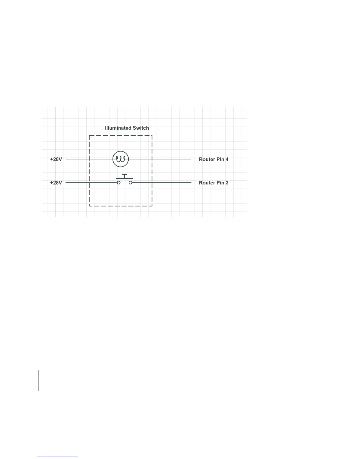
The digital output can be configured for a few different uses such as an indication of the reception of a
Fleetlink Message. It is a “Current Sinking” output. It typically drives two terminal peripheral devices
such as lamps, annunciators, and relays. One terminal of these devices is typically connected to a power
source of up to 50 Volts DC, and the other terminal is connected to the digital output of the Airtext Router
(pin 4).
A Sample wiring diagram showing typical Digital Input and Output connections is shown below.
ARINC Configuration
ARINC configuration specifies which ARINC labels are expected at which bus speed (High or Low), on
which port (1 or 2). Typically GAMA labels are predictable. Some FMS publish different data on
different labels.
Configurations can be created by Send Solutions Technical Staff to support most Flight Management
Systems. Some information about the hardware installation, FMS type, and customer preferences is
required. Airtext routers have two ARINC input ports. Each port can be independently set to LOW or
HIGH speed. Typically only ARINC Ground speed or the Weight on Wheels signal is needed to
automate the take-off and landing functionality. Optional customer preference information might include
Altitude, Headwind/tailwind, ETE, Date/Time, GPS Location, Distance to destination, Destination
Airport. Ground speed, Air speed, Mach, etc.
Send Solutions recommends that the connection to the airplanes FMS to be GAMA HIGH Speed Protocol
with physical connection of the FMS ARINC-429 wiring to the Airtext routers port 1.
Doc# 2016-25-05 Rev F Technical Support 678-208-3087 Ext #1 Airtext Installation Manual
Page 18

Standard ARINC-429 labels:
Label: 75 ACTIVE WAYPOINT FROM/TO DATA (DSC)
Label: 113 Message Checksum
Label: 125 GREENWICH MEAN TIME (BCD)
Label: 204 BARO CORRECTED ALTITUDE (Feet) (BNR)
Label: Mach number (BNR)
Label: 210 TRUE AIR SPEED (BNR)
Label: 260 DATE (BCD)
Label: 300 STN DECLINATION, TYPE AND CLASS (BNR)
Label: 301 MESSAGE CHARACTERS 7-9 (BNR)
Label: 302 MESSAGE CHARACTERS 10-12 (BNR)
Label: 303: Record (Message) Length/Type/Number
Label: 304: IDENT Characters 1 - 3
Label: 305: IDENT Characters 4 - 6
Label: 306: Waypoint Latitude
Label: 307: Waypoint Longitude
Label: 310 PRESENT POSITION LATITUDE (BNR)
Label: 311 PRESENT POSITION LONGITUDE (BNR)
Label: 312 GROUND SPEED (BNR)
Label: 351 DISTANCE TO DESTINATION (VIA FLIGHT PLAN) (BNR)
Label: 352 ESTIMATED TIME TO DESTINATION (VIA FLIGHT PLAN) (BNR)
17
Additional configuration specifies how the altitude is presented and if checksums are valid.
POST-INSTALLATION CHECKOUT
After Airtext is installed, complete the checkout procedures herein to verify proper basic operation.
Mounting, Wiring, and Power Checks
Check that Airtext is mounted rigidly. Do not connect Airtext to the aircraft harness until the following
checks have been performed:
1. Check that all cables are properly secured and shields (if used) are connected at one end only. Either to
the shield block of the connector at the Airtext router, at ONE of the disconnects, or at the far termination
of the cable. Check the movement of the flight and engine controls to verify there is no interference
between the cabling and control systems.
2. Prior to powering up Airtext, check the wiring harness for point to point continuity to expose any faults
such as shorting to ground or swapped pins. Any faults or discrepancies must be corrected before
proceeding.
3. After accomplishing a continuity check, perform power and ground checks to verify proper power
distribution to Airtext. Any faults or discrepancies should be corrected at this time. Remove power from
Doc# 2016-25-05 Rev F Technical Support 678-208-3087 Ext #1 Airtext Installation Manual
Page 19

18
the circuit powering the Airtext router upon completion of the harness checkout. Airtext connector can be
plugged in after completion of the continuity and power checks.
4. Ground checks: Enable power to Airtext when the aircraft placed outside of the hanger with a view of
the sky and out of the shadow of tall buildings. Open the Airtext app and send an Airtext text message to
your own or your co-workers phone. The message should be delivered within a minute or two. See
troubleshooting section below if it is not delivered. Respond to that message after receipt. Again the
message should be delivered back to the plane within a minute or two. Detailed instructions to load and
use the APP are contained in the next section of this document.
5. Checkout is considered complete when the text message makes the full round trip.
Bluetooth Texting Setup
When the Airtext router is powered on, it will immediately go into a mode to discover new users. It will
form a Dynamic Bluetooth LE bond with up to 16 simultaneous users. It will also form a Dynamic
Bluetooth LE bond with up to 64 users on a round-robin connect and release process. That list of bonded
devices is rebuilt with each new flight. Explicit or permanent Bluetooth Pairing the way that a hands-free
cell phone head set is not needed for Texting.
Doc# 2016-25-05 Rev F Technical Support 678-208-3087 Ext #1 Airtext Installation Manual
Page 20

19
First time use.
Airtext system needs three things: Airtext router installed in airplane, Airtext application hosted on a
compatible Android or iOS phone or tablet, and a ground based person using a standard SMS cell phone
to exchange texts with. The Airtext router connects flying users to ground based users anywhere in the
world without altitude or geographical limitations.
The Airtext application is available as a free download on the Google Play Store for Android devices, and
available on the Apple App Store for iOS devices. It is installed the same as any other common
application or game from the stores.
Send your first Text.
Place airplane in area with clear view of sky (Airtext rarely works inside hanger and is extremely sluggish
under an awning).
Enable power to airplane from ground cart, APU, or main engines.
Launch the Airtext application on your phone or tablet the same way as any other typical application by
tapping the Airtext icon.
Enter your full name on the welcome screen and press the Enter or Done button. This name will be the
name that is contained in the canned welcome message that each new ground user will see so it should be
immediately recognizable.
Press the small Green or Blue button in the bottom right of the Airtext screen to create a new Chat session
with a person to whom you wish to communicate with on the ground. Enter their phone number on the
top line of the Airtext screen. The application will start listing the phone numbers from the contacts in the
phone if any are close to matching. Alternately you can type a name that is in the phones contact list and
again, close matches will appear. Click a name or phone number if a perfect match is listed or simply
complete the new phone number.
Click the text area at the bottom of the screen to enable the keyboard on the phone and enter the first text
that you wish to send. Press the send button to the right of that text area. A small check mark will appear
on the message within a few seconds indicating that the Airtext router in the airplane received the
message. The message will be sent to the ground user in just a few seconds. Wait a bit for the person to
read the message and send a reply. That reply will appear on the screen just below the text that you sent
them. Repeat as necessary. Each flying user can set up chats with multiple ground users. Each chat has
its own section and message history the same as common cell phones.
At the conclusion of the flight, the flying user simply closes the application and they are done. The
Airtext router is simply powered down along with the rest of the airplane. There is no shutdown
procedure or process required.
Doc# 2016-25-05 Rev F Technical Support 678-208-3087 Ext #1 Airtext Installation Manual
Page 21

20
Bluetooth Voice Setup (Airtext+ only)
Airtext+ uses common Bluetooth hands free headsets the same way that they are used with a cell phone.
The Airtext app permits the user to dial with its keypad or from the devices phone book and the
audio/voice is handled with the hands free headset. Just like with a cell phone, a Bluetooth hands free
headset must be paired and connected. Airtext can be paired with multiple hands free headsets. Bluetooth
Pairing means that the router has saved information that permits fast and easy connection. Bluetooth
Connection means that there is currently data flowing between the two devices. The Airtext router
automatically connects to the last used headset if it is currently available. An icon displaying head set
connection status is shown at the top of the Voice Dial screen. It is bright blue when connected and grey
when not connected.
Just as with any cell phone and hands free headset, users must initiate a headset disconnection (button
push or power down) on the headset before the Airtext router or a common cell phone can connect to a
different headset.
A pop-up will appear on the screen asking the user to confirm the new Bluetooth pairing. Bluetooth setup
only needs to be run when pairing with a device for the first time. Once a connection is established with a
Bluetooth device, Airtext+ will automatically connect to the Bluetooth device upon power-up. Airtext+
will save multiple Bluetooth hands free headset device pairings.
Make your first Voice call
The system is 95% setup for voice after all the steps for a text conversation have been performed.
The Voice dialing menu is not enabled or visible by default. Navigate to the advanced menu in your
Airtext app and enable the “voice dialing” option.
A voice call is started from the Airtext menu. Access the menu in the Airtext app by sliding the menu out
from the left edge on Android, or selecting the dialer tab at the bottom of the Apple app. Select the voice
dialer and you can select someone from your contacts or dial a new number just like you did for texting.
Connect a Bluetooth hands free headset as described in the previous section if its connection icon is not
bright blue.
Select a contact from your phone book and press dial. You will hear progress tones on the head set as the
system connects.
Iridium calls take a few extra seconds to connect, but once connected, act just like any other cell phone
call. Simply select the “disconnect” button on the Airtext app or the “disconnect” button on the headset
when the call is complete. The Iridium call will also be disconnected if the ground user hangs up or the
Bluetooth headset loses connection with the Airtext router for more than 30 seconds.
Optional Configuration
Almost all of Airtext and Airtext+ functionality is enabled and ready to use without any custom
configuration. There are a few features that enhance operation that can be enabled or configured from the
Doc# 2016-25-05 Rev F Technical Support 678-208-3087 Ext #1 Airtext Installation Manual
Page 22

21
Android or iOS (Apple) Airtext applications. These features have very likely already been enabled or
configured for your specific install at the factory during the final QA shipment process.
If changes to the configuration or additional configuration is desired, then it can be accomplished using
the standard Airtext app. New users should make configuration changes while on a phone call with a
member of the Send Solutions technical support staff. Some Airtext configuration settings are only
available when Dealer Mode is activated. Call Send Solutions technical support for the instructions for
accessing the advanced setup screens.
Testing Optional features
There is a menu section in the Airtext app for installation. It permits the installer to view ARINC
messages on a label by label basis, and view the state of the discrete digital inputs typically connected to
weight on wheels and antenna sharing relay status.
Doc# 2016-25-05 Rev F Technical Support 678-208-3087 Ext #1 Airtext Installation Manual
Page 23

22
Software Updates
A compatible PED with an active Dealer Mode subscription, and an active Send Solutions Dealer account
is required to perform software updates. To activate Dealer Mode, contact Airtext Product Support at
(678) 208-3087 extension #1. Request access to update Airtext firmware as a Send Solutions Dealer.
A detailed firmware update procedure is described in Appendix A of this document. In summary:
Turn on power to the Airtext router and enable the Airtext App. Clear view of sky and satellite
connection is NOT needed.
Open the Dealer menu and click to get the latest version of firmware from the Send Solutions servers and
put it on the phone while in WiFi or Cellular data plan range. Then click to send that firmware from the
phone to the router.
Older versions of firmware take a little over 15 minutes to update. Newer versions of the firmware
transfer in about 3 minutes.
CONTINUED AIRWORTHINESS
Maintenance of Airtext transceiver unit is on condition. No general maintenance, air filter cleaning, or
system monitoring is required.
Doc# 2016-25-05 Rev F Technical Support 678-208-3087 Ext #1 Airtext Installation Manual
Page 24
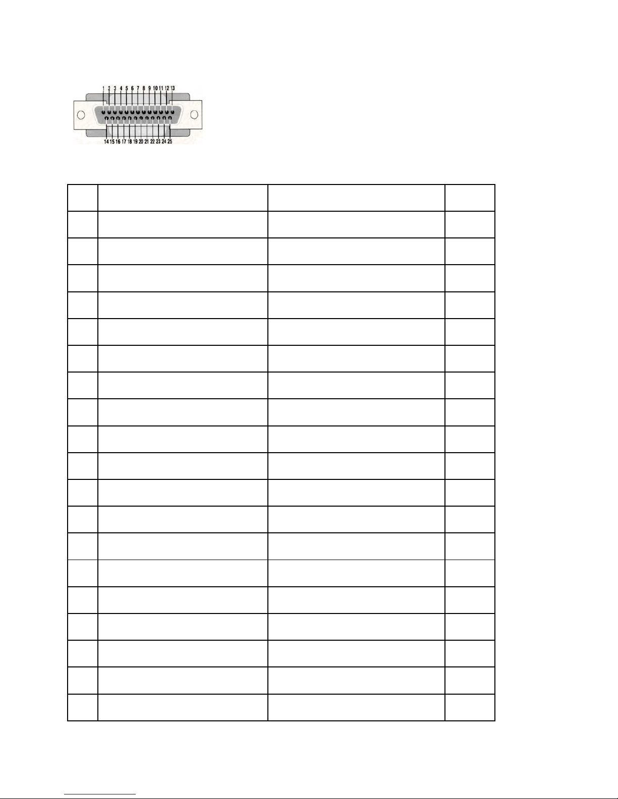
CONNECTOR PINOUT
Pin # Airtext
Airtext +
I/O
1. Aircraft Power
Aircraft Power
(Plus)
In
2. Aircraft Power Retur
n (Minus)
Aircraft Power Return (Minus)
--
3. Digital Input
#1
Digital Input
#1 In
4. Digital Output
Digital Output
Out
5. Reserved
Reserved
--
6. ARINC RX 1 A
ARINC RX 1 A
In
7. ARINC RX 2 A
ARINC RX 2 A
In
8. Ground
Ground
--
9. CAN Bus High 1
CAN Bus High 1
In
10. CAN Bus High 2
CAN Bus High 2
In
11. RS-485 A/ RS
-
232 TX
RS-
485 A/ RS
-
232 TX Port 1
Out
12. Reserved
RS-
485 A Port 2
Out
13. Ground
Ground
--
14. Reserved
Reserved
--
15. Reserved
+5V Output (.25 Amp Max)
Out
16. Digital Input #
2 Digital Input #2
In
17. Digital Input #3
Digital Input #3
In
18. Reserved
Reserved
--
19. ARINC RX1 B
ARINC RX1 B
In
INFORMATION
Table 6-1 Airtext Pinout List
23
Doc# 2016-25-05 Rev F Technical Support 678-208-3087 Ext #1 Airtext Installation Manual
Page 25
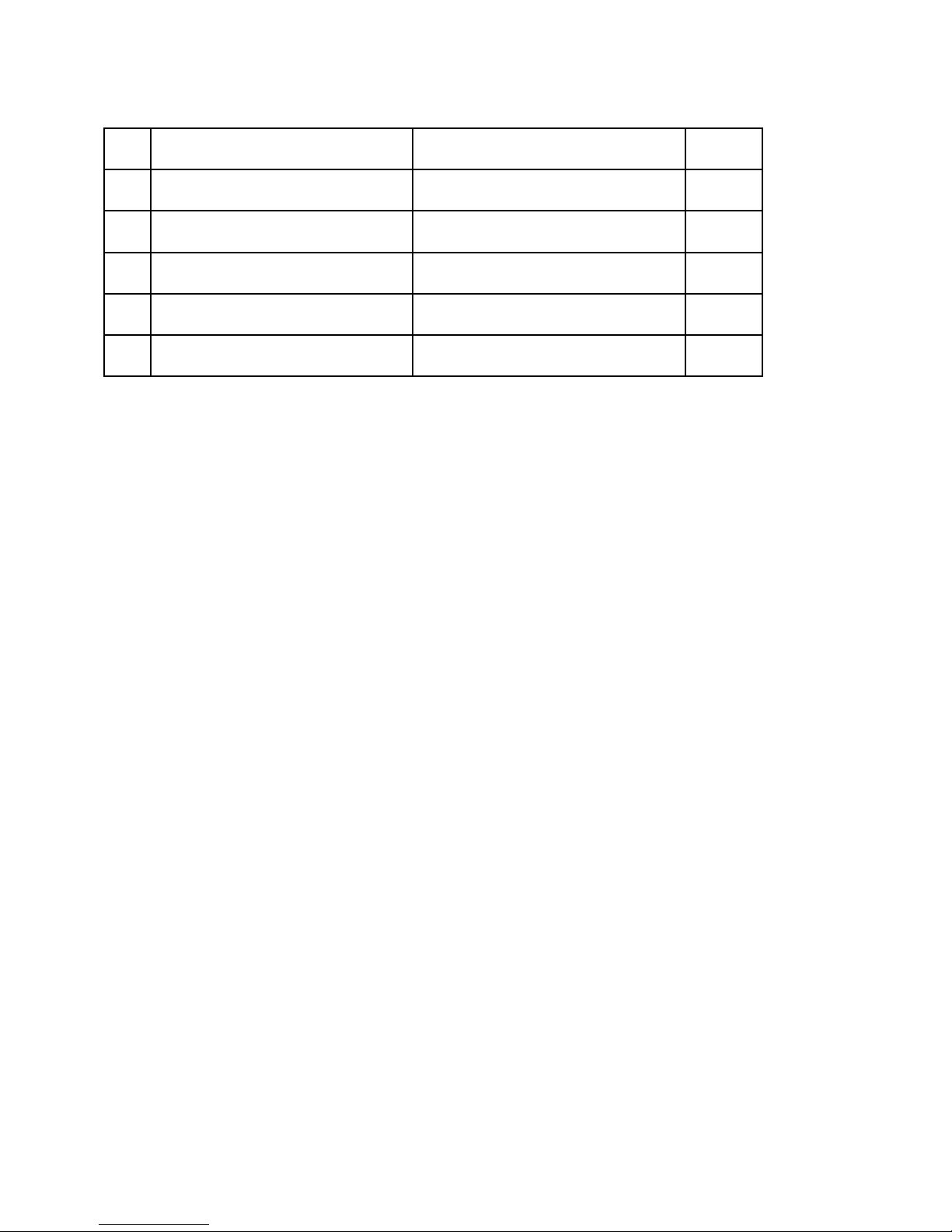
20. ARINC RX2 B
ARINC RX2 B
In
21. CAN Bus Low 1
CAN Bus Low 1
Out
22. CAN Bus Low 2
CAN Bus Low 2
Out
23. Ground
Ground
--
24. RS-485B/ RS
-
232 RX
RS-
485B/ RS
-
232 RX Port 1
In
25 Reserved
RS-
485 B Port 2
In
TROUBLESHOOTING
Initial Installation Troubleshooting.
24
Enable the “Show Connection Icon” option in the menu if not already enabled. Is it green, yellow, or
grey? Green indicates successful recent connection between the phone/tablet and the Airtext router.
Yellow indicates a marginal or sluggish connection. If the icon is grey then there is no Bluetooth
connection. This may be caused by loss of power, missing Bluetooth antennas, incompatible phone, or
disabled Bluetooth on the phone.
Do you get a checkmark in the bottom right corner of a message immediately when you send it, or is there
a delay? The check mark indicates successful reception of the message by the Airtext router. This is the
first step in getting your message to the ground.
If you get check marks with each sent message and the messages are still not making it to the ground.
Did you call us to have the Airtext router commissioned or provisioned? Airtext routers are typically
shipped in their enabled condition. If the Airtext unit was shipped more than a month or two prior to
installation, then it may be in IRIDIUM SUSPEND condition in order to suspend monthly data charges.
Please call Send Solutions Technical support to put the Airtext router in operate condition. Please have
the Airtext Serial number or the Iridium IMEI number (from the label on the rear of the unit) available
when calling.
Select the “Send Health Message” from the menu. This exercises the Airtext system from the flying PED
to the Public Switched Telephone network and back again by sending a message around the full loop and
reporting the number of seconds for that full round trip.
Is there a problem with a specific region or country? Try texting a USA SMS phone number.
Doc# 2016-25-05 Rev F Technical Support 678-208-3087 Ext #1 Airtext Installation Manual
Page 26
25
Are you sure that the antenna for the Airtext router is designed for and certified for use with the Iridium
satellite system? Is it an unknown model or might it be designed for GPS, XM, or some other avionics
use?
Is the cable between the Airtext router and the Iridium antenna in good condition? Is it crimped, crushed,
or abraded? Tighten Type TNC connectors to a torque of 0.45 to 0.68 N-m (4 to 6 inch-lbs.). Is the
connector tight but cross threaded or jammed?
Could you have excessive RF attenuation (power loss) between the Airtext unit and the Iridium antenna?
What kind of cable is used for the Iridium antenna? Are connector adapters needed at either end of the
antenna cable? Are there disconnects in the antenna cable? Are all connectors used between the Airtext
router and the antenna specifically designed for use with the exact cable used? What is the length of the
antenna cable? What is the loss per foot rating on the cable? Ensure that all this information does not
explain more than a 3dB power loss for the antenna system.
Are the Bluetooth antennas connected? Are they bent or broken? If they have cables, are they crimped,
crushed, or abraded?
Is the Iridium antenna mounted outside on the top of the fuselage? Is it adjacent to an INMARSAT,
Satellite TV, Satellite Radio, or an avionics antenna? Is it in the shadow of a vertical stabilizer? Is it in
view of a RADAR antenna?
Is the Airtext unit getting power? Check for open circuit breakers.
Do you have a Voice/Data switch? (Antenna sharing relay). If so, then change the state of the relay to
check if perhaps the switch is labeled incorrectly or installed backwards.
Where is the Airtext router mounted? Under a Carbon fiber floor? Behind metal honeycomb partitions
hatches, and doors. Is there 6 inches of open space between the Bluetooth antennas and nearby plumbing,
wiring, or ribs? Any nearby high current wires from strobes, valves, power converters, galley appliances,
microwave ovens, avionics equipment?
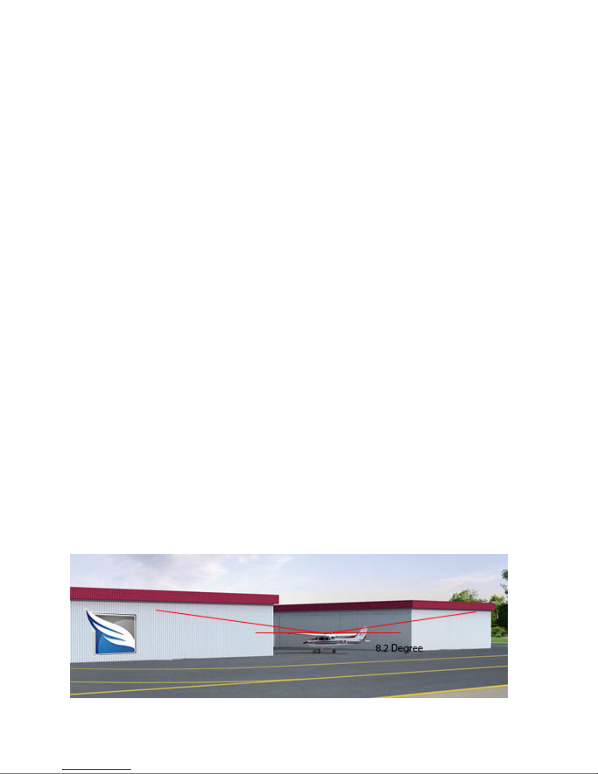
Where is the airplane? Is it in the hangar on in a deep canyon formed from buildings/hangars?
Optimum location permits 360-degree view of horizon with no obstructions extending into the 8.2 degree
(from horizontal plane) free zone.
Doc# 2016-25-05 Rev F Technical Support 678-208-3087 Ext #1 Airtext Installation Manual
Page 27

26
If service has slowly degraded over time.
Is the cable between the Airtext router and the Iridium antenna in good condition? Is it crimped, crushed,
or abraded? Tighten Type TNC connectors to a torque of 0.45 to 0.68 N-m (4 to 6 inch-lbs). Is the
connector tight but cross threaded or jammed?
Are the Bluetooth antennas connected? Are they bent or broken? If they have cables, are they crimped,
crushed, or abraded?
Has other equipment be added since Airtext was installed? Have there been any wiring changes or
interior work that may have crushed or damaged cables or wiring?
If Service Suddenly Stopped Working.
Did you pause or suspend your service using the Customer Web Portal? Owners can put their Airtext unit
in IRIDIUM SUSPEND condition in order to suspend monthly data charges. The Suspend/Active
condition can be inquired and changed using the Airtext Customer Portal. Send Solutions Technical
support can also let you know the condition and change it for you. Please have the Airtext Serial number
or the Iridium IMEI number (from the label on the rear of the unit) available when calling.
Check your Airtext Customer Portal. It can let you know if your service is in suspend mode or if there are
billing or accounting problems.
Do you have a Voice/Data switch? (Antenna sharing relay). Try changing the switch position.
Check for an open Circuit breaker.
Although unlikely, consider hardware failures of the Antenna, Antenna cable, or Airtext router.
Lightning strike damage from the antenna connection or the power connection is not impossible. Contact
Send Solutions technical support for assistance in diagnosing hardware related problems
PED (Personal Electronics Device) APP Problems
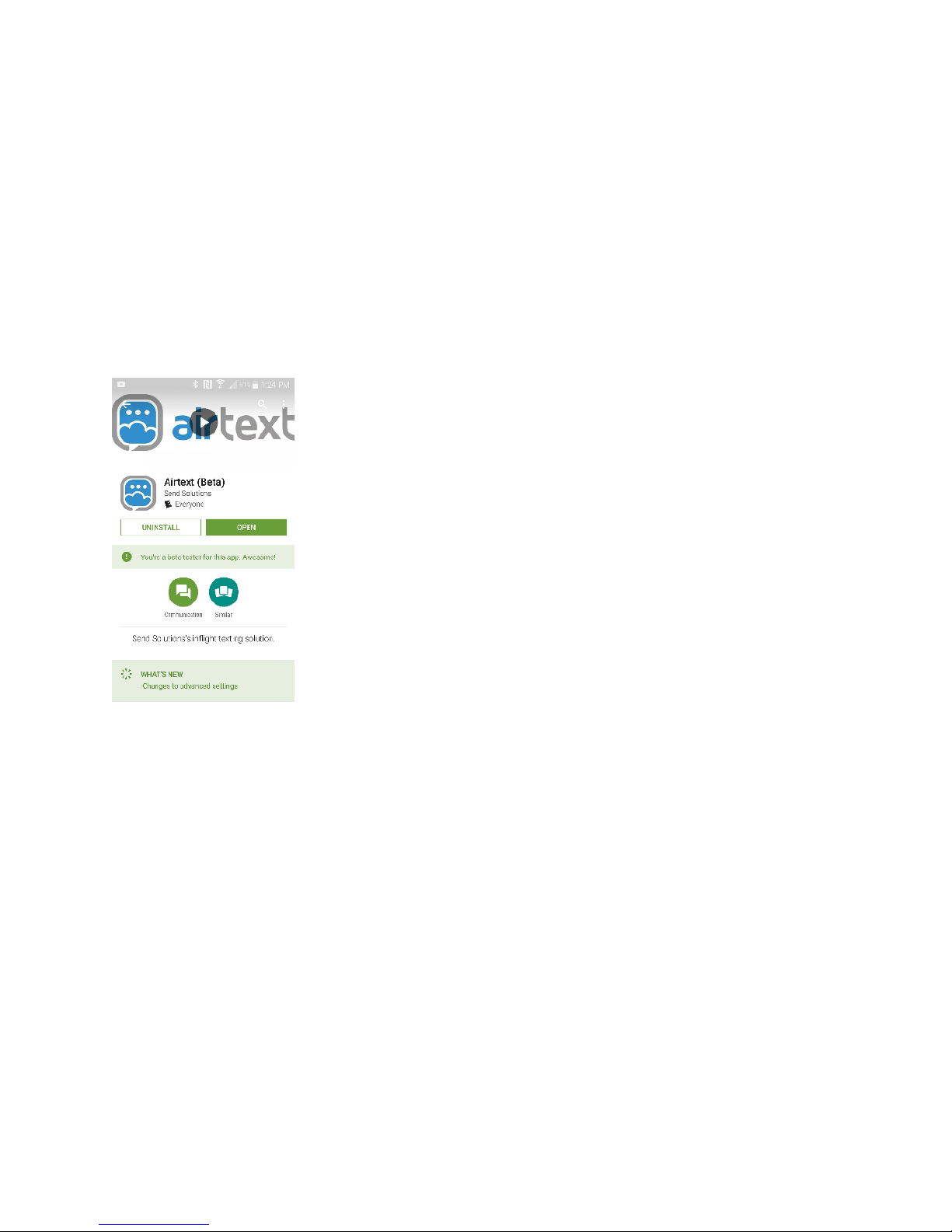
Get the free Airtext App from the Apple App Store or Google Play Store. Search for Airtext – Inflight
Text Messaging and this logo:
Doc# 2016-25-05 Rev F Technical Support 678-208-3087 Ext #1 Airtext Installation Manual
Page 28

27
Compatible PED (Personal Electronics Device)
Android devices must run on Android version 5 or above. The following devices are known to
work. Most new devices are expected to work.
•
Google Nexus 5, 6, & 6P
•
HTC One mini 2*
•
LG G2, G4
•
OnePlus One, X
•
Samsung Galaxy S2, S4, S4 Mini, S5, S6, S7, Note 2, Note 4
•
Sony Xperia Z, Z3
Apple iOS devices should as a minimum run iOS version 9.3.
•
iPhone 4s and above.
•
iPads should be 3rd generation or above.
•
iPod Touch should be 5th generation or above.
Airplane mode: The exact operation of Airplane mode varies from phone to phone, and even from one
operating system release to another. The most common effect of enabling airplane mode is that it turns
off all possible radios in the cell phone. Most devices let you enable airplane mode and then permit the
user to re-enable just the radios that they want to use. Be sure to enable Bluetooth after enabling airplane
mode in order to use Airtext.
Wired Data Problems
Airtext routers support several wired data connections to aircraft systems and companion products.
ARINC-429 and RS-232 are commonly used to input a variety of avionics information such as GPS,
Altitude, and Ground Speed. A common problem with ARINC is swapped A and B wires. Messages will
still appear if the wires are swapped, but the channel may have unexpected labels, and those labels may
contain wildly incorrect data. The most common problem with RS-232 is improper configuration caused
by a mis-communication of the manufacturer, model number, and firmware version of the avionics that it
is connected to. Verify that info and Send Solutions Technical support staff can verify the configuration.
Voice Problems
The menu item for Voice dialing is not made available to users unless enabled via the dealer menu. Call
Send Solutions technical support @ 678-208-3087 for instructions on how to enable the voice dialer
menu item.
If the Airtext router works for texting but not voice, then check to see if the Iridium Voice SIM card is
expired, depleted, suspended, or has billing or accounting problems.
Check to see if the Bluetooth hands free headset is paired and connected.
Doc# 2016-25-05 Rev F Technical Support 678-208-3087 Ext #1 Airtext Installation Manual
Page 29

28
What more can be done?
Send Solutions Technical support staff has advanced Network analysis tools available during normal
business hours 8am to 5pm Eastern Standard Time. (GMT-5). Please call to schedule a time when we can
send test and tracing messages between the Send Solutions ground based servers and your Airtext router.
Aircraft antenna installation vendors have test equipment and historical knowledge that could be useful.
Several Iridium and Satellite communication resources are available on the web.
http://www.beamcommunications.com/media/com_beamcommunications/uploads/downloads/Iridium_an
tenna_guide_installation_and_user_manual.pdf
Doc# 2016-25-05 Rev F Technical Support 678-208-3087 Ext #1 Airtext Installation Manual
Page 30
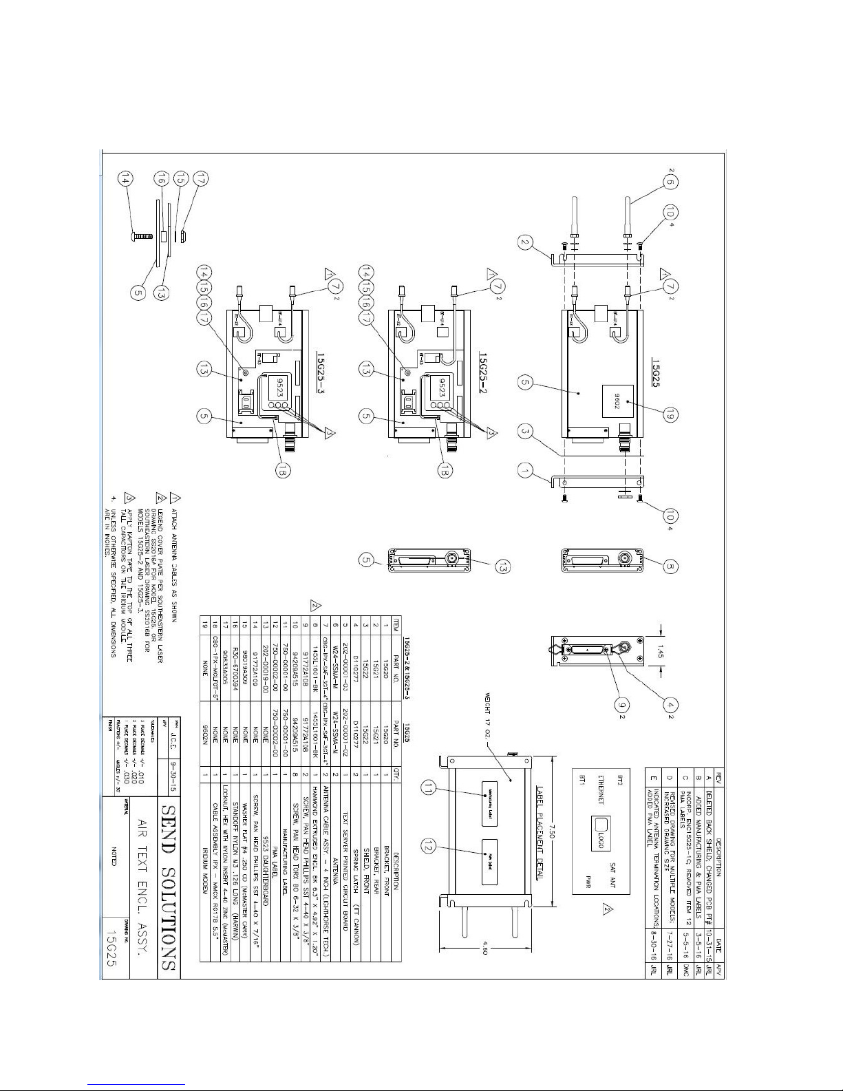
Figure 1 - OUTLINE AND INSTALLATION DRAWING
29
Doc# 2016-25-05 Rev F Technical Support 678-208-3087 Ext #1 Airtext Installation Manual
Page 31
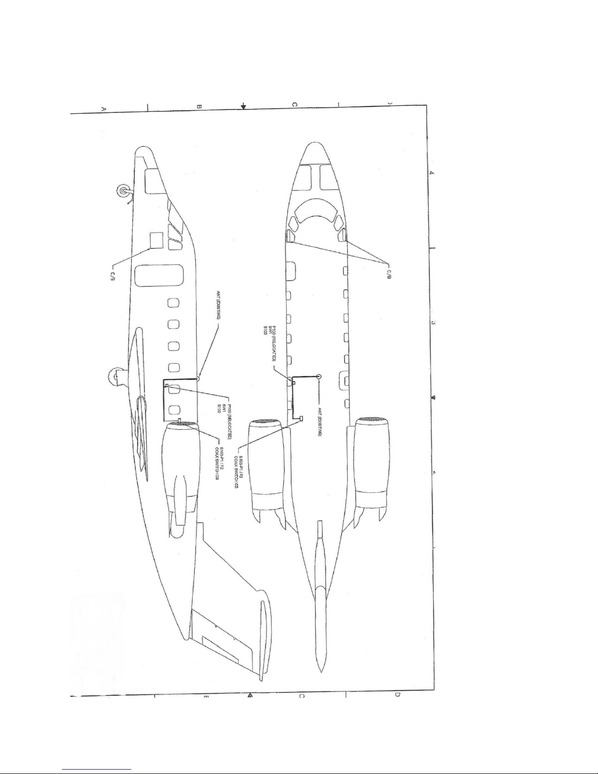
Figure 2 - INTERCONNECT DRAWING
30
Doc# 2016-25-05 Rev F Technical Support 678-208-3087 Ext #1 Airtext Installation Manual
Page 32
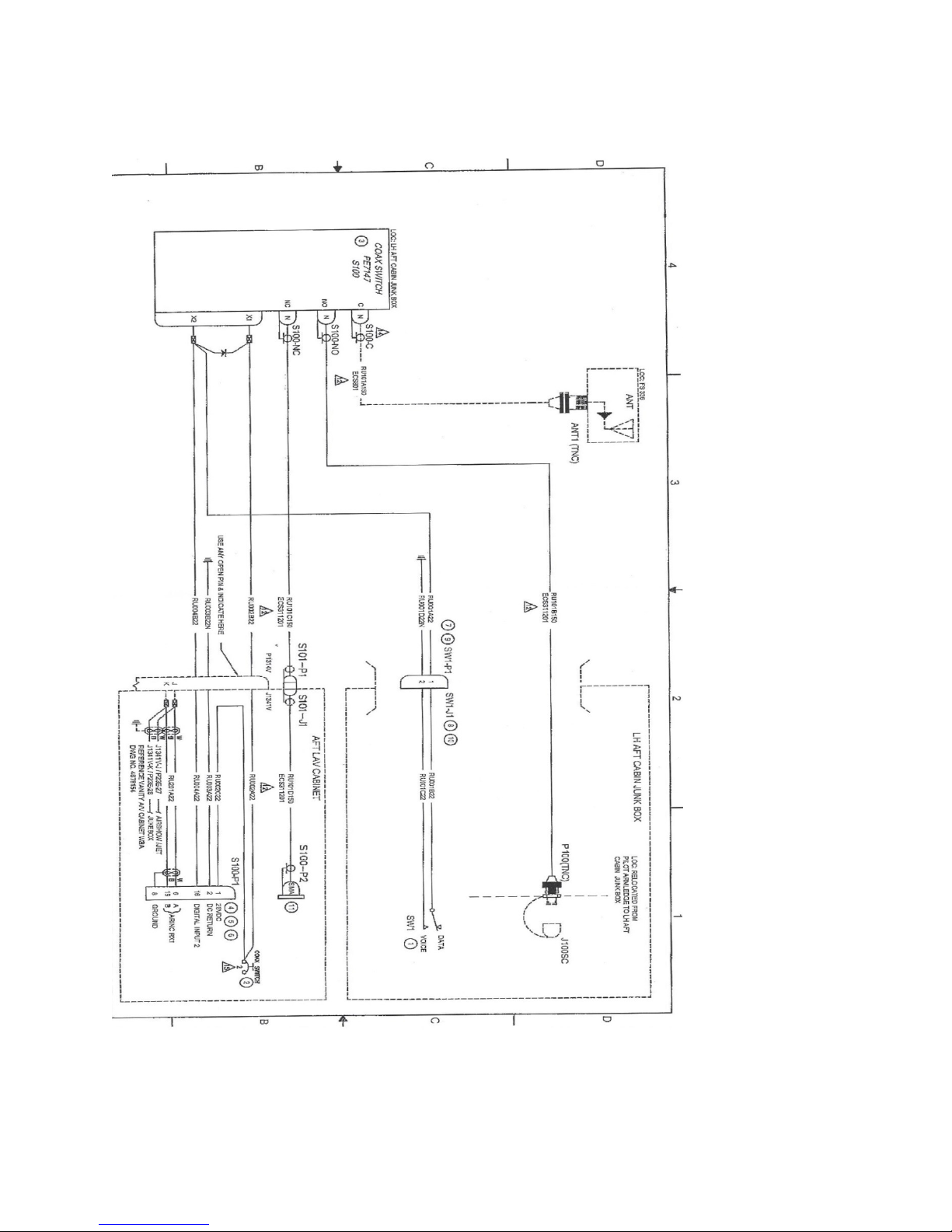
Figure 3 - Sample Wiring Diagram
31
Doc# 2016-25-05 Rev F Technical Support 678-208-3087 Ext #1 Airtext Installation Manual
Page 33
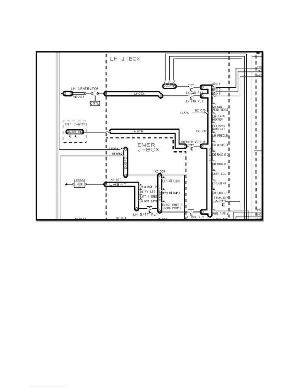
Figure 4 - Sample Interior Power Circuitry – Shedable load
32
NOTES
1 ALL WIRES 22 AWG OR LARGER UNLESS OTHERWISE SPECIFIED.
2 GROUND DESIGNATIONS: SHIELD BLOCK GROUND AIRFRAME GROUND
3 Airtext SUPPORTS BOTH HIGH AND LOW SPEED ARINC 429 CONNECTIONS ON THE ARINC
429 INPUT PORT.
Airtext - Iridium Antenna Interconnect
Ensure that all components used to connect Airtext to the antenna are designed to work with each other.
Slight changes in connector part numbers can mean the difference in a rugged and reliable resulting cable
with perfect performance and an unreliable texting system.
Doc# 2016-25-05 Rev F Technical Support 678-208-3087 Ext #1 Airtext Installation Manual
Page 34
33
Appendix A: Airtext router Firmware Updates
Update Airtext router using ANDROID phone or Tablet
Section I
If you have an android tablet or phone that has the Airtext application already installed then skip to
section II.
Airtext app can be found on the Google Play store. It will be the one with the Sends Solutions LOGO.
The latest version will always be available in the play store. Install and launch just like any other app.
Section II
Open the app by selecting the Airtext Icon.
Enable Bluetooth if asked.
Doc# 2016-25-05 Rev F Technical Support 678-208-3087 Ext #1 Airtext Installation Manual
Page 35
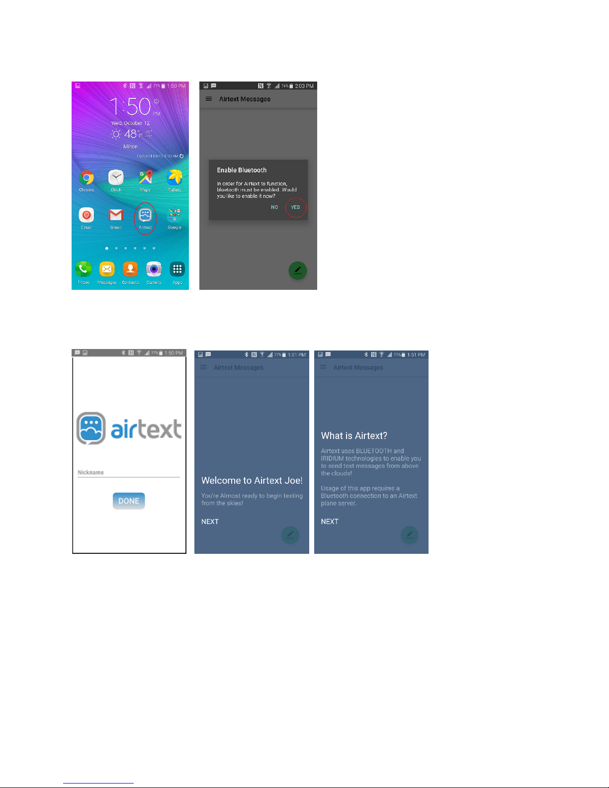
Input your full name such as “Joe Smith” if asked to do so. Step through all of the welcome screens if
they show up. The user name you enter here will be the name that ground users will see when they
receive a text from you via the Airtext Service.
34
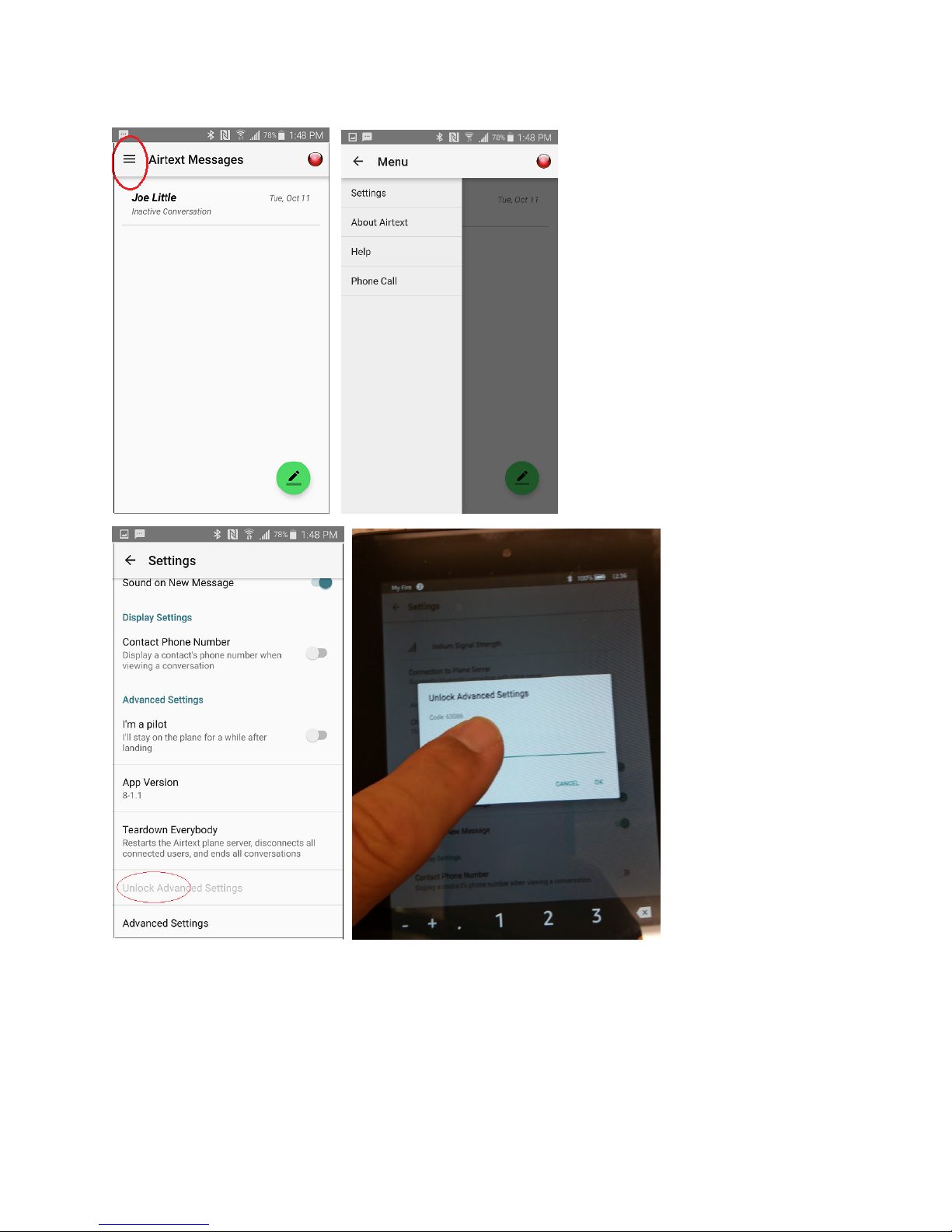
Select the Menu system on the upper left corner. It is indicated with the three lines.
Doc# 2016-25-05 Rev F Technical Support 678-208-3087 Ext #1 Airtext Installation Manual
Page 36
35
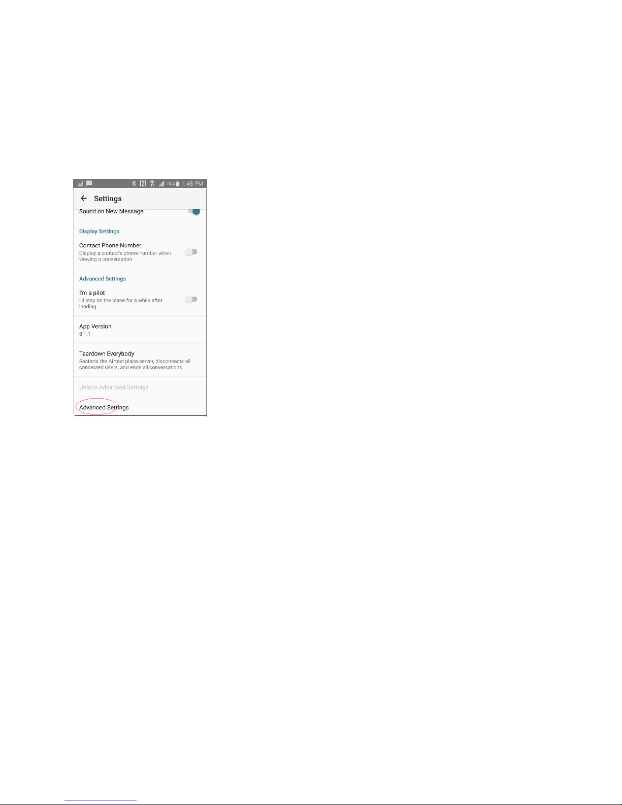
Select the Settings menu, then select the last menu item called “unlock Advanced settings”. A password
window will pop up with a randomly generated code number. Please call Send Solutions Technical
Support: Telephone: 678-208-3087 Voice Menu 1. Have the code number ready and a member of the
technical support staff will issue a password with a limited expiration time.
Doc# 2016-25-05 Rev F Technical Support 678-208-3087 Ext #1 Airtext Installation Manual
Page 37
36
Enter that password into the menu screen then Press OK. A new menu item appears at the bottom of the
menus that permits access all of the advanced settings. Take care while in these menus to guard against
inadvertent or unintended changes.
A new menu item appears at the bottom called advanced settings. Select it.
If you already have the latest router firmware saved on the Android device, then skip to section III.
Load the latest firmware from the internet to your Android Phone or Tablet:
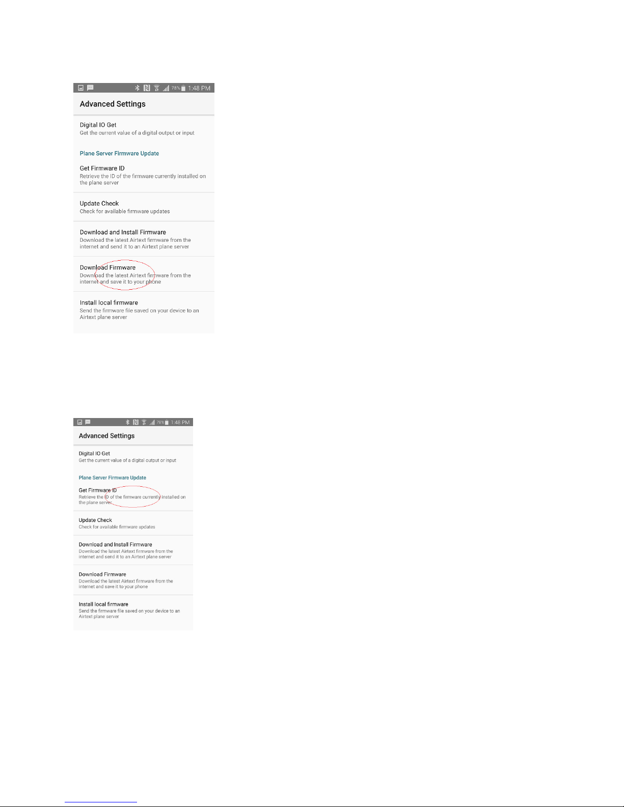
While the Android device is within WiFi or Cell Data coverage area, scroll down to the menu item called
Download Firmware and select it. It will load the latest router firmware from the Airtext Servers and
place a copy in the Android device. The Android device is now ready to update the firmware on the
Airtext router.
Doc# 2016-25-05 Rev F Technical Support 678-208-3087 Ext #1 Airtext Installation Manual
Page 38
Section III
37
Power up the Airtext router and move within the range of its Bluetooth radios. While in the advanced
menu, select “Get Firmware ID”
This takes a few seconds. The screen should show the current version
firmware that is on the Airtext router. It should be something like
“10041610”. Record that value. It is in Month/Day/Year/Hour format.
Press “ok” to dismiss that screen. This proves that the Android device and
the Airtext router have proper Bluetooth connectivity.
Doc# 2016-25-05 Rev F Technical Support 678-208-3087 Ext #1 Airtext Installation Manual
Page 39
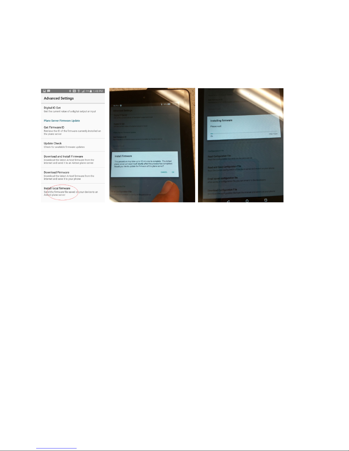
Select “install Local Firmware”. Select OK on the popup to approve the load process. There will be a
five or ten second delay while the devices connect then a pop up appears with a progress bar. It takes
approximately 10 minutes to transfer the new program.
38
Note: Android phones and tablets typically sleep if no activity is detected on the screen while running on
battery power. You can touch the screen every minute or so or connect to a charger to keep it awake.
The firmware update process continues during sleep, but it may run at half speed.
The firmware load is complete when the progress bar disappears.
Re-select the “Get Firmware ID” menu item as you did at the beginning of section III when the load is
complete. Ensure that the firmware version is different. As of the creation date of this document, the
latest revision is 02071710.
Please call Send Solutions Technical Support - Telephone: 678-208-3087 Voice Menu 1. With any
questions or comments.
Doc# 2016-25-05 Rev F Technical Support 678-208-3087 Ext #1 Airtext Installation Manual
Page 40

39
Doc# 2016-25-05 Rev F Technical Support 678-208-3087 Ext #1 Airtext Installation Manual
 Loading...