

Sencotel Granitore 1, Granitore 2 FF, Granitore 2, Granitore 1 FF, Granitore 3 Operating Instructions Manual [en, es, it, de]
...Page 1
MANUALE ISTRUZIONI
Leggere attentamente queste istruzioni d’uso prima di utilizzare la macchina
MANUAL DE EMPLEO
Leer atentamente estas instrucciones de uso antes de utilizar la máquina
OPERATING INSTRUCTIONS
Read these operating instructions carefully before using the machine
BETRIEBSANLEITUNG
Diese Bedienungsanleitung ist vor dem ersten Gebrauch der Maschine
aufmerksam zu lesen
MODE D’EMPLOI
Lire attentivement ce mode d’emploi avant d’utiliser la machine
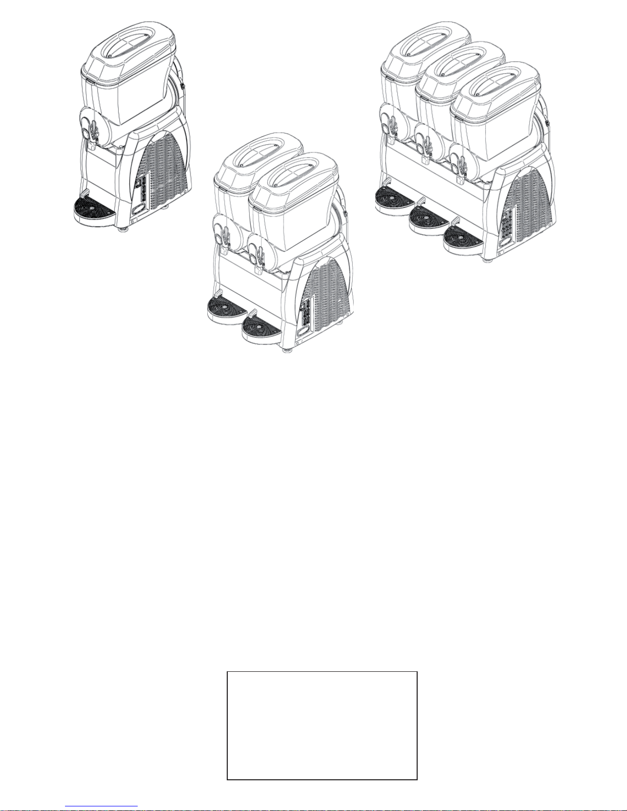
Granitore - Granizadora - Granita machine
Gramolate-Geräts - Distributeur de granités
SL310005700 Ed.00 - 04-2011
Page 2
Per le macchine marcate CE si riporta quanto segue:
Il costruttore dichiara sotto la propria esclusiva responsabilità che la macchina alla
quale si riferisce il presente manuale (vedi targa dati applicata in copertina alla presente), è conforme ai requisiti essenziali previste dalle seguenti direttive:
• 2006/42/CE Direttiva “Macchine”
• 2006/95/CE Direttiva “Bassa Tensione”
• 2004/108/CE Direttiva “EMC”
• 97/23/CE Direttiva “PED”
• 2004/1935/CE Regolamento “Materiali e oggetti a contatto
con i prodotti alimentari”
Für Maschinen mit CE-Kennzeichnung wird Folgendes angegeben
Der Hersteller erklärt in eigener Verantwortung, dass die Maschine, auf die sich
das vorliegende Handbuch bezieht (siehe Datenschild, das auf dem Deckblatt des
vorliegenden Handbuchs angebracht ist), den von den folgenden Richtlinien vorgesehenen Mindestanforderungen entspricht:
• 2006/42/CE Richtlinie “Maschinen”
• 2006/95/CE Richtlinie “Niederspannung”
• 2004/108/CE Richtlinie “EMC”
• 97/23/CE Richtlinie “PED”
• 2004/1935/CE Verordnung “Materialien und Gegenstände in
Kontakt mit Lebensmitteln”
Pour les machines portant la marque CE:
Le constructeur déclare sous sa propre responsabilité que la machine faisant objet
du présent manuel (voir plaquette de données prèsente en couverture), répond aux
caractéristiques essentielles prévues par les directives:
• 2006/42/CE Directive “Machines”
• 2006/95/CE Directive “Basse Tension”
• 2004/108/CE Directive “EMC”
• 97/23/CE Directive “PED”
• 2004/1935/CE Règlementation “Matériaux et objets en
contact avec les produits alimentaires”
For machines with CE marking:
The manufacturer hereby declares, under its own exclusive responsibility, that the
machine named in this manual (see the plate on the cover of the manual) conforms
to the essential requirements of the following directives:
• 2006/42/CE “Machinery” Directive
• 2006/95/CE “Low Voltage” Directive
• 2004/108/CE “EMC” Directive
• 97/23/CE “PED” Directive
• 2004/1935/CE Regulation “Materials and items in contact
with foodstuffs”
Para las máquinas con la marca CE se señala lo siguiente:
El fabricante declara bajo la propia exclusiva responsabilidad que la máquina a la
cual se refi ere el presente manual (ver placa de datos aplicada en la tapa de la pre-
sente), cumple los requisitos esenciales previstos por las siguientes directivas:
• 2006/42/CE Directiva “Máquinas”
• 2006/95/CE Directiva “Baja Tensión”
• 2004/108/CE Directiva “EMC”
• 97/23/CE Directiva “PED”
• 2004/1935/CE Reglamento “Materiales y objetos en contacto
con los productos alimentarios”
xxxxxxxxxx xxxxxxxxxx
xxxxxxxxxx
xxxxxxxxxx
xx/xxxxxxxx
N°
......V ......Hz ......W
R...... ......gr
Nome del costruttore
e ragione sociale
Modello macchina
Anno di produzione
numero di serie
Caratteristiche
elettriche
Tipo di gas refrige-
rante impiegato e
quantità
xxxxxxxxxx xxxxxxxxxx
xxxxxxxxxx
xxxxxxxxxx
xx/xxxxxxxx
N°
......V ......Hz ......W
R...... ......gr
Nombre del fabricante y número de identifi cación a efectos
del IVA
Modelo máquina
Año de fabricación/
número de serie
Características
eléctricas
Tipo de gas refrige-
rador empleado y
cantidad
xxxxxxxxxx xxxxxxxxxx
xxxxxxxxxx
xxxxxxxxxx
xx/xxxxxxxx
N°
......V ......Hz ......W
R...... ......gr
Manufacturer’s name
Machine model
Year of production/
serial number
Electrical specifi ca-
tions
Type and quantity of
coolant gas
xxxxxxxxxx xxxxxxxxxx
xxxxxxxxxx
xxxxxxxxxx
xx/xxxxxxxx
N°
......V ......Hz ......W
R...... ......gr
Nom du constructeur
et raison sociale
Modèle machine
Année de fabrication/
numéro de série
Caractéristiques élec-
triques
Type de gaz réfri-
gérant employé et
quantité
xxxxxxxxxx xxxxxxxxxx
xxxxxxxxxx
xxxxxxxxxx
xx/xxxxxxxx
N°
......V ......Hz ......W
R...... ......gr
Name des Herstellers
und der Firma
Maschinenmodell
Herstellungsjahr/Seri-
ennummer
Elektrische Eigen-
schaften
Benutzter Kühlgastyp
und Menge
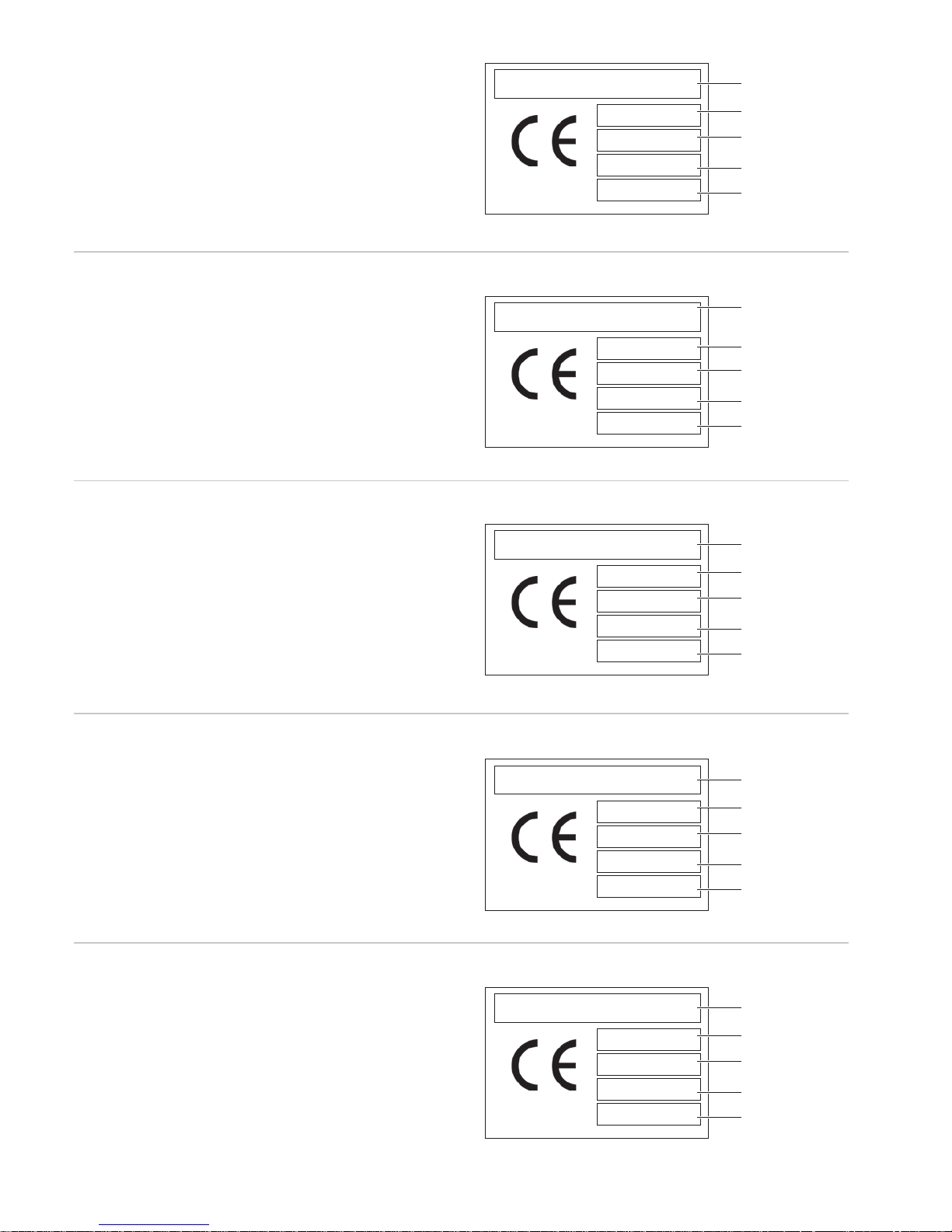
Ogni macchina riporta in targa dati le seguenti informazioni:
Cada máquina contiene en la placa de datos las siguientes informaciones:
The rating plate on each machine bears the following information:
Jede Maschine gibt auf dem Datenschild die folgenden Informationen an:
Chaque machine est munie d’une plaquette de données contenant les
informations suivantes:
Page 3

Versione Italiana .......................................................... Pag.2 - IT
Versión española ........................................................Pag.2 - ES
English version .......................................................... Pag.2 - EN
Deutsche Version ...................................................... Pag.2 - DE
Version française ........................................................Pag.2 - FR
Istruzioni originali
Traducción de las instrucciones originales
Translation of the original instructions
Überesetung der originalanleitungen
Traduction des instructions originales
Page 4

- 2 _IT- SL310005700 Ed.00 - 04-2011
SOMMARIO
1. INFORMAZIONI GENERALI .......................3
1.1. Costruttore ...........................................................3
1.2. Addetti ..................................................................3
1.3. Struttura del manuale ...........................................3
1.3.1. Scopo e contenuto ...........................................3
1.3.2. Destinatari ........................................................3
1.3.3. Conservazione .................................................3
1.3.4. Simboli Utilizzati ...............................................3
2. DESCRIZIONE MACCHINA ........................4
2.1. Utilizzo della macchina .........................................4
2.2. Componenti Principali ..........................................4
2.3. Dati Tecnici ...........................................................4
2.4. Descrizione funzioni pannello comandi ................5
3. SICUREZZA .................................................6
3.1. Norme Generali di sicurezza ................................6
3.2. Funzioni d’arresto .................................................6
3.3. Targhe ..................................................................6
4. MOVIMENTAZIONE E STOCCAGGIO ........6
4.1. Imballo ..................................................................6
4.2. Trasporto e movimentazione ................................7
4.3. Stoccaggio ...........................................................7
5. INSTALLAZIONE .........................................7
5.1. Elenco accessori in dotazione ..............................7
5.2. Montaggio-Piazzamento ......................................7
5.3. Smaltimento imballo .............................................8
5.4. Collegamento elettrico .........................................8
6. FUNZIONAMENTO ......................................8
6.1. Preparazione prodotto ..........................................8
6.2. Avvio Granitore ....................................................9
6.3. Avvio Granitore 1 (Termostato elettronico) .........10
6.4. Avvio Granitore 2/3 (Termostato elettronico) ......10
6.5. Regolazione consistenza granita .......................11
6.6. Erogazione granita .............................................11
6.7. Situazioni d’emergenza ......................................12
6.8. Acc. opzionali (Sistema di Chiusura) .................12
6.9. Acc. opzionali (Temporizzatore) .........................12
6.9.1. Impostazione ora corrente .............................12
6.9.2. Funzionamento della macchina con
temporizzatore ...............................................12
7. PULIZIA E MANUTENZIONE ....................13
7.1. Svuotamento vasche ..........................................13
7.2. Smontaggio rubinetto .........................................14
7.3. Smontaggio vasca e coperchio ..........................14
7.4. Lavaggio e sanitizzazione componenti ..............15
7.5. Assemblaggio componenti lavati. .......................15
7.6. Ciclo di risciacquo ..............................................16
7.7. Pulizia vasca raccogli gocce ..............................17
7.8. Coperchio luminoso ...........................................17
7.8.1. Sostituzione della lampadina .........................17
7.9. Pulizia condensatore ..........................................18
7.9.1. Pulizia condensatore Granitore 1 - 1FF. .........18
7.9.2. Pulizia condensatore
Granitore 2-2FF-3-3FF ...................................18
7.10. Manutenzione periodica .....................................19
8. DEMOLIZIONE ..........................................19
9. PROBLEMI - CAUSE - RIMEDI .................20
10. SCHEMI ELETTRICI DI PRINCIPIO ..........21
GARANZIA .......................................................28
Page 5
SL310005700 Ed.00 - 04-2011 - 3 _IT-
1. INFORMAZIONI GENERALI
1.1. Costruttore
Le indicazioni relative al costruttore sono riportate sulla targhetta dati
presente nella prima e/o nell’ultima pagina del manuale.
1.2. Addetti
Alla macchina possono accedere due addetti con mansioni differenti
Operatore
Persona con adeguate conoscenze tecniche nella preparazione dei prodotti
che utilizza la macchina per l’erogazione delle granite nel rispetto delle normative igieniche vigenti.
Dopo aver preso visione del presente manuale, è in grado d’eseguire:
• le normali operazioni di caricamento e/o sostituzione dei prodotti di consumo;
• la corretta erogazione del prodotto;
• la pulizia e la sanitizzazione della macchina.
Tecnico specializzato
Persona che, presa visione del presente manuale, è specializzata nell’installazione uso e manutenzione del granitore:
• è in grado d’eseguire interventi di riparazione in caso di gravi malfunzionamenti ed essere, inoltre, a conoscenza del presente Manuale e di tutte le
informazioni relative alla Sicurezza:
• è in grado di comprendere il contenuto del Manuale ed interpretare correttamente Disegni e Schemi;
• è a conoscenza delle principali Norme igieniche, antinfortunistiche, tecnologiche e di sicurezza;
• ha esperienza specifi ca nella manutenzione dei granitori;
• sa come comportarsi in caso di Emergenza, dove reperire i mezzi di protezione individuale e come usarli correttamente.
É vietato fare utilizzare la macchina a persone che non abbiano
i requisiti richiesti.
1.3. Struttura del manuale
Il Cliente deve leggere con estrema attenzione le informazioni riportate nel presente Manuale.
1.3.1. Scopo e contenuto
Questo Manuale ha lo scopo di fornire al Cliente tutte le informazioni necessarie
all’installazione, la manutenzione e l’uso del granitore.
Prima di effettuare qualsiasi operazione sulla Macchina, gli operatori ed i tecnici specializzati devono leggere attentamente le
istruzioni contenute nella presente pubblicazione.
In caso di dubbi sulla corretta interpretazione delle istruzioni, interpellare il Costruttore per ottenere i necessari chiarimenti.
É vietato effettuare qualsiasi operazione senza avere letto e ben
compreso il contenuto del presente manuale.
1.3.2. Destinatari
Il Manuale in oggetto è rivolto agli operatori e ai Tecnici specializzati.
Gli operatori non devono eseguire operazioni riservate ai tecnici specializzati.
Il costruttore non risponde di danni derivanti dalla mancata osservanza di questo divieto.
Il manuale istruzioni è parte integrante del prodotto acquistato e lo deve accompagnare sempre anche in caso di passaggio a successivi proprietari del
prodotto.
1.3.3. Conservazione
Il Manuale d’istruzioni deve essere conservato nelle immediate vicinanze della
Macchina.
Per poter garantire l’integrità e la consultabilità nel tempo del presente manuale
si raccomandano le seguenti avvertenze:
• Impiegare il manuale in modo tale da non danneggiare tutto od in parte il
contenuto.
• Non asportare, strappare o riscrivere per alcun motivo parti del manuale.
• Conservare il manuale in zone protette da umidità e calore, in modo tale che
non ne venga pregiudicata la qualità della pubblicazione e la leggibilità in
tutte le sue parti.
Nel caso in cui il presente manuale sia danneggiato o perso,
si dovrà richiederne immediatamente un’altra copia al costruttore o al distributore autorizzato del paese dove la macchina è
utilizzata.
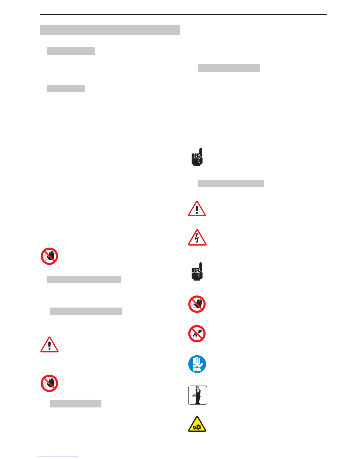
1.3.4. Simboli Utilizzati
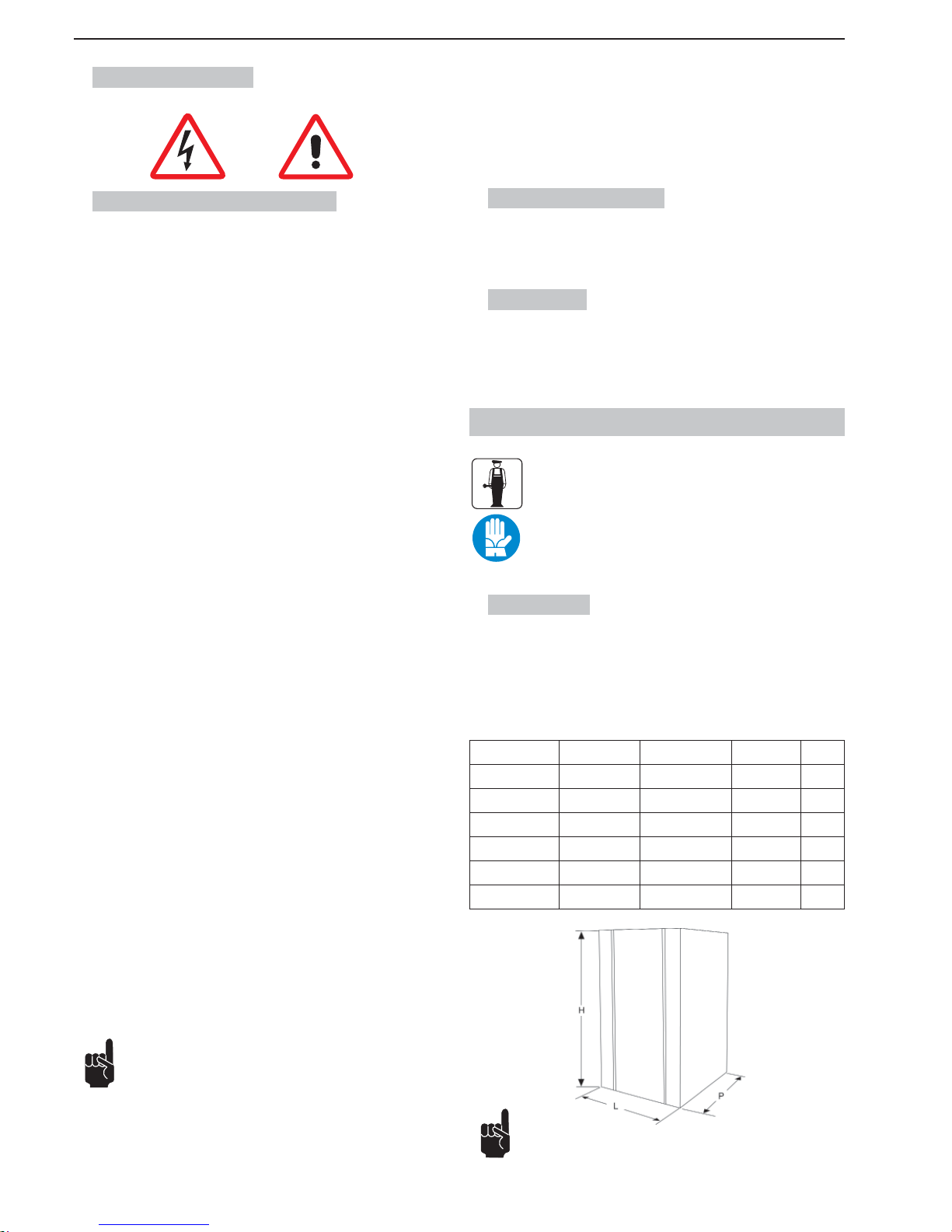
PERICOLO GENERICO
Indica un pericolo con rischio, anche mortale, per l’Utilizzatore. In
questo caso si deve prestare la massima attenzione e si devono
attuare tutti gli interventi per operare in modo sicuro.
PERICOLO DI FOLGORAZIONE
Segnala al personale interessato, che l’operazione descritta presenta, se non effettuata nel rispetto delle normative di sicurezza, il
rischio di subire uno shock elettrico.
AVVERTENZA
Indica un’avvertenza od una nota su funzioni chiave o su informazioni utili.
Prestare la massima attenzione ai blocchi di testo indicati da questo
simbolo.
DIVIETO
La presenza di questo segnale indica le operazioni che sono assolutamente da evitare poiché creano pericolo per l’Utilizzatore e le
persone che operano nelle vicinanze.
DIVIETO DI SPEGNERE GLI INCENDI CON ACQUA
La presenza di questo segnale indica il divieto di spegnere gli incendi
con l’acqua o con qualunque sostanza che la contenga.
PROTEZIONE PERSONALE
La presenza del simbolo a fi anco della descrizione richiede l’utilizzo
di protezioni personali da parte dell’operatore, essendo implicito il
rischio d’infortunio.
TECNICO SPECIALIZZATO
Identifi ca gli interventi che possono essere eseguiti solo da perso-
nale tecnico specializzato.
ORGANI IN MOVIMENTO
Identifi ca il pericolo dovuto agli organi in movimento presenti nella
macchina. Spegnere la macchina prima d’effettuare qualsiasi operazione.
Page 6
- 4 _IT- SL310005700 Ed.00 - 04-2011
2. DESCRIZIONE MACCHINA
2.1. Utilizzo della macchina
La macchina ad uso professionale che state utilizzando, è idonea alla produzione
di granite e bibite fredde. Nel caso sia utilizzata con prodotti a base latte e/o
quando le leggi lo prevedano a seconda dei prodotti utilizzati, deve essere dotata
dell’opzione “visualizzatore di temperatura” del prodotto in vasca. Inoltre, sono
tassativamente da rispettare le normative vigenti per i prodotti utilizzati.
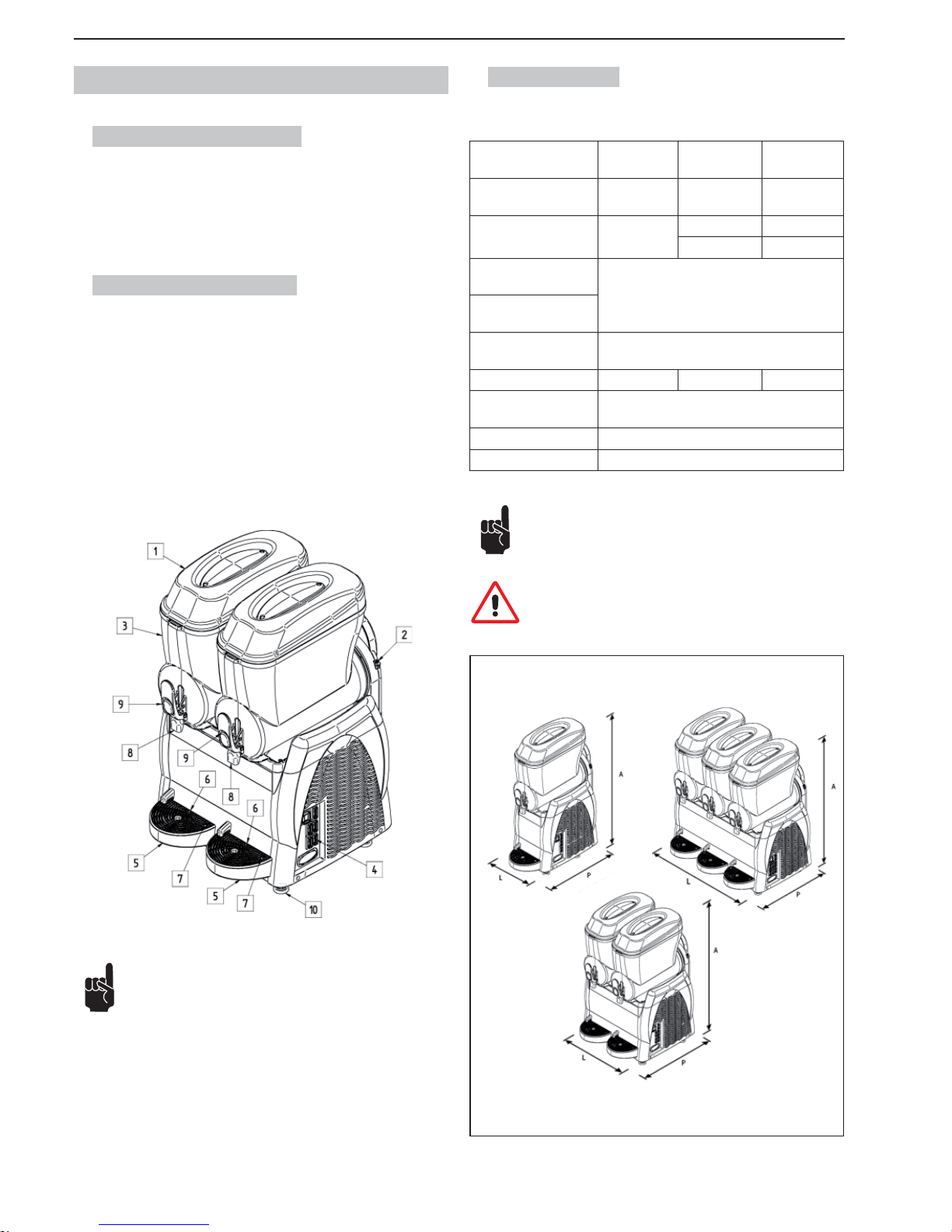
2.2. Componenti Principali
I componenti principali che costituiscono la macchina sono:
1 Coperchio vasca
2 Regolazione densità
3 Vasca
4 Pannello comandi
5 Vasca raccogli gocce
6 Griglia
7 Galleggiante vaschetta piena
8 Erogatore prodotto
9 Leva erogazione prodotto
10 Piedini
2.3. Dati Tecnici
Di seguito sono riportati i dati e le caratteristiche tecniche.
Modello
Granitore 1
Granitore 1 FF
Granitore 2
Granitore 2 FF
Granitore 3
Granitore 3 FF
Dimensioni del granitore
L x P x A - (cm).
27 x 52 x 81 47 x 52 x 81 67 x 52 x 81
Peso (kg).
(vasca vuota)
29
47 68
52 70
Potenza Massima Assorbita (W).
Vedi targhetta dati tecnici posta sul fi anco della
macchina
Tensione di funzionamento (V).
Temperatura di funzionamento.
Min. 20°C
Max. 32°C
Numero vasche. 1 2 3
Capacità di ciascuna va-
sca acqua (l.).
12
Pressione sonora. << 70 dB
A
Classe. N
Per rendere più agevole la lettura delle istruzioni, nella presente
pubblicazione sono utilizzate le seguenti abbreviazioni:
Granitore 1, identifi ca il Granitore a (1) una vasca;
Granitore 2, identifi ca il Granitore a (2) due vasche;
Granitore 3, identifi ca il Granitore a (3) tre vasche;
Granitore 1 FF, identifi ca il Granitore a (1) una vasca con impianto frigorifero
Fast Freeze;
Granitore 2 FF, identifi ca il Granitore a (2) due vasche con impianto frigorifero
Fast Freeze;
Granitore 3 FF, identifi ca il Granitore a (3) tre vasche con impianto frigorifero
Fast Freeze.
Nota: Il costruttore si riserva il diritto di apportare eventuali modifi che alla macchina senza alcun preavviso.
Attenzione! Qualsiasi modifi ca e/o aggiunta d’accessori, deve
essere esplicitamente approvata e realizzata a cura del Costruttore.
Fig.1
Fig.2
Page 7
SL310005700 Ed.00 - 04-2011 - 5 _IT-
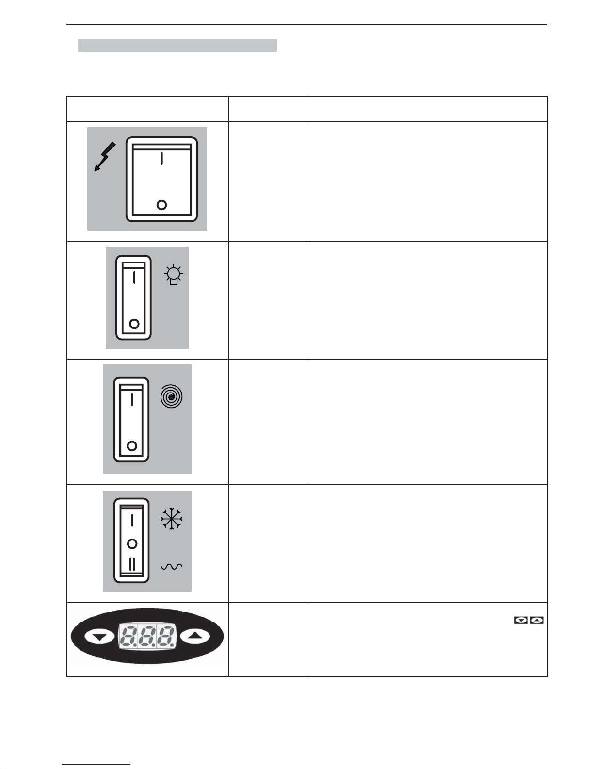
2.4. Descrizione funzioni pannello comandi
I comandi della macchina sono sul pannello posto nella parte laterale.
COMANDO MODELLO FUNZIONE
TUTTI
Interruttore Generale: ha la funzione di comandare:
- l’accensione della macchina;
- lo spegnimento di tutte le funzioni presenti sulla macchina.
TUTTI
Interruttore Illuminazione coperchio: accende/spegne l’illuminazione (se
presente) sui coperchi delle vasche.
TUTTI
Interruttore miscelazione vasca (uno per ogni vasca): ha la funzione di
comandare l’accensione e lo spegnimento del motoriduttore che aziona la
coclea di miscelazione del prodotto della relativa vasca.
TUTTI
Deviatore impianto frigo (uno per ogni vasca):
- sulla posizione “0” l’impianto frigorifero è disattivato;
- sulla posizione “I” l’impianto frigorifero è attivato per la produzione di granite;
- sulla posizione “II” l’impianto frigorifero è attivato per la produzione di
bibite fredde.
TUTTE LE VERSIONI
CON TERMOSTATO
ELETTRONICO
Termostato elettronico:
- Visualizza la temperatura del prodotto in vasca e tramite i tasti
è possibile variare la temperatura della bibita quando la macchina lavora
in modalità “bibita fredda”.
Page 8
- 6 _IT- SL310005700 Ed.00 - 04-2011
3. SICUREZZA
3.1. Norme Generali di sicurezza
• Leggere attentamente tutto il manuale istruzioni.
• Il collegamento alla rete elettrica deve essere eseguito in conformità alle
norme di sicurezza vigenti nel paese d’utilizzazione.
• La presa, alla quale collegare la macchina, deve essere:
- conforme al tipo di spina installata nel medesimo;
- dimensionata per rispettare i dati della targhetta dati sul fi anco dell’appa-
recchio.
- collegata ad un effi ciente impianto di messa a terra.
- collegata ad un impianto con differenziale e magnetotermico.
• Il cavo d’alimentazione, non deve:
- entrare in contatto con qualsiasi tipo di liquido: pericolo di scosse elettriche e/o incendio;
- essere schiacciato e/o entrare in contatto con superfi ci taglienti;
- essere utilizzato per spostare la macchina;
- essere utilizzato se risulta danneggiato;
- essere manipolato con le mani umide o bagnate;
- essere avvolto in una matassa quando la macchina è in funzione.
- essere manomesso.
• È vietato:
- installare la macchina con modalità differenti da quelle descritte nel
Cap.5.
- installare la macchina in zone nelle quali può essere utilizzato un getto
d’acqua.
- utilizzare la macchina in prossimità di sostanze infi ammabili e/o esplosive.
- lasciare alla portata dei bambini sacchetti di plastica, polistirolo, chiodi
ecc. in quanto sono fonti di potenziali pericoli.
- lasciare che i bambini abbiano la possibilità di giocare e sostare nelle
vicinanze della macchina.
- utilizzare ricambi non consigliati dalla ditta costruttrice.
- apportare qualsiasi modifi ca tecnica alla macchina.
- immergere la macchina in qualsiasi tipo di liquido.
- lavare la macchina con un getto d’acqua.
- utilizzare la macchina in modi differenti da quelli descritti nel manuale.
- utilizzare la macchina in condizioni psicofi siche alterate; sotto l’infl uenza
di droghe, alcool, psicofarmaci, ecc.
- installare la macchina sopra ad altre apparecchiature.
- l’utilizzo della macchina in atmosfera esplosiva, aggressiva o ad alta concentrazione di polveri o sostanze oleose in sospensione nell’aria;
- l’utilizzo della macchina in atmosfera a rischio d’incendio;
- l’utilizzo della macchina per erogare sostanze non idonee alle caratteristiche della stessa;
• Prima di pulire la macchina accertarsi che la spina sia scollegata dalla presa di
corrente; non lavare la macchina con benzina e/o solventi di qualsiasi natura.
• Ogni riparazione può essere eseguita solo da un Centro Assistenza Autorizzato dal Costruttore e/o comunque da personale specializzato ed addestrato.
• Non ostruire le griglie poste a lato della macchina.
• Non collocare la macchina vicino ad impianti di riscaldamento (come stufe o
caloriferi).
• In caso di incendio utilizzare estintori ad anidride carbonica (CO
2
). Non uti-
lizzare acqua od estintori a polvere.
In caso di uso improprio decade ogni forma di garanzia e il costruttore declina ogni responsabilità per danni a persone e/o
cose.
É da considerarsi uso improprio:
- qualsiasi utilizzo diverso da quello previsto e/o con tecniche diverse da quelle indicate in questa pubblicazione;
- qualsiasi intervento sulla macchina che sia in contrasto con le indicazioni
riportate in questa pubblicazione;
- qualsiasi utilizzo dopo manomissioni a componenti e/o dopo alterazioni ai
dispositivi di sicurezza;
- qualsiasi utilizzo dopo riparazioni eseguite con componenti non autorizzati
dal costruttore;
- l’installazione all’esterno dell’apparecchio.
3.2. Funzioni d’arresto
Le funzioni di arresto della macchina, sono demandate all’interruttore generale.
3.3. Targhe
NESSUNA TARGA PRESENTE SULLA MACCHINA DEVE ESSERE RIMOSSA, COPERTA O DANNEGGIATA, IN PARTICOLAR MODO QUELLE CHE
SVOLGONO FUNZIONE DI SICUREZZA.
4. MOVIMENTAZIONE E STOCCAGGIO
Tutte le operazioni descritte nel capitolo 4 sono di esclusiva
competenza dei tecnici specializzati anche in sollevamen to e
movimentazione di macchine imballate e disim ballate che, in
funzione delle caratteristiche e del peso dell’oggetto da movimentare, dovranno organizzare tutte le sequenze operative e
l’impiego di mezzi ade guati ad operare nel rigoroso rispetto
delle norme vi genti in materia.
4.1. Imballo
La macchina viene spedita pronta per l’uso imballata con una scatola di cartone. La scatola di cartone è composta da una base e da un coperchio; questi
sono fermati tramite due reggette di nylon.
DIMENSIONI E PESO DELL’IMBALLO
Larghezza (L) Profondità (P) Altezza (H) Peso
Granitore 1
340 mm 540 mm
930 mm
32 kg
Granitore 1 FF
340 mm 540 mm
930 mm
32 kg
Granitore 2
560 mm
540 mm
930 mm 52 kg
Granitore 2 FF
560 mm
540 mm
930 mm 57 kg
Granitore 3 770 mm 540 mm
930 mm 72 kg
Granitore 3 FF 770 mm 540 mm
930 mm 74 kg
Nota: le dimensioni ed il peso dell’imballo sono indicativi.
Fig.3
Page 9
SL310005700 Ed.00 - 04-2011 - 7 _IT-
4.2. Trasporto e movimentazione
Assicurarsi che nessuno sosti nel raggio d’azione delle operazioni di sollevamento e movimentazione del carico e, in condizioni diffi coltose, predisporre perso nale addetto al controllo
degli spostamenti da effet tuare.
La movimentazione manuale della macchina deve essere eseguito da almeno
due persone.
La macchina deve essere spostata in posizione verticale e solo dopo aver
svuotato ogni vasca dal prodotto in essa contenuto.
Sollevare l’imballo, e trasportarlo con cautela evitando percorsi accidentati e
prestando attenzione all’ingombro e ad eventuali sporgenze.
Attenzione: è vietato praticare tagli aggiuntivi sull’imballo.
Danni alla macchina causati durante il Trasporto e la Movimentazione,
non sono coperti da GARANZIA.
Riparazioni o sostituzioni di parti danneggiate sono a carico del Cliente.
4.3. Stoccaggio
Prima di procedere allo stoccaggio della macchina e quando
si riavvia la macchina dopo un periodo di stoccaggio, eseguire
un’accurata pulizia e sanitizzazione della macchina.
Attenzione: nell’operazione di stoccaggio non sovrapporre più di due
macchine.
In caso di lunga inattività, la Macchina deve essere immagazzinata con le precauzioni relative al luogo ed ai tempi di Stoccaggio:
• immagazzinare la Macchina in luogo chiuso;
• proteggere la Macchina da urti e sollecitazioni;
• proteggere la Macchina dall’umidità e da escursioni termiche elevate;
• evitare che la Macchina venga a contatto con sostanze corrosive.
MAX
MAX
Fig.4
5. INSTALLAZIONE
Tutte le operazioni descritte nel capitolo 5 sono di esclusiva
competenza di tecnici specializzati che dovranno organizzare
tutte le sequenze operative e l’impiego di mezzi ade guati ad
operare nel rigoroso rispetto delle norme vi genti in materia.
La macchina deve essere installata all’interno di un edifi cio illuminato, areato e
provvisto di pavimento solido, livellato (inclinazione inferiore a 2°) e fermo.
L’apparecchio è di tipo con sorveglianza e dovrà essere installato in luoghi dove potrà essere osservato da personale addestrato.
Attenzione: è vietato installare la macchina in posti ove possa
essere raggiunta, toccata e/o azionata da persone differenti da
quelle specifi cate nel paragrago 1.2.
La macchina deve funzionare in ambienti ove la temperatura sia compresa tra
i 20°C ed i 32°C.
5.1. Elenco accessori in dotazione
• Vaselina: per lubrifi care tutte le parti indicate nel presente manuale dopo le
operazioni di lavaggio e sanitizzazione.
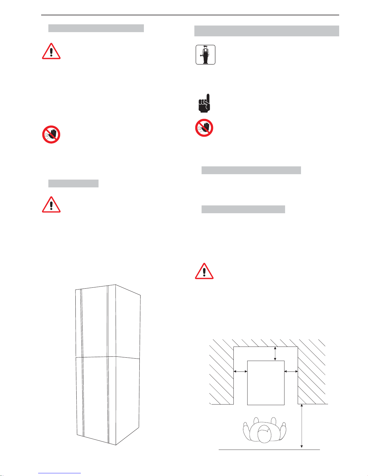
5.2. Montaggio-Piazzamento
L’operatore deve verifi care quanto segue:
• che il locale sia stato predisposto all’istallazione della macchina;
• il piano sul quale viene installato la macchina sia piano, solido e fermo;
• il locale sia suffi cientemente illuminato, areato, igienico e la presa di corrente
sia facilmente raggiungibile.
Devono essere lasciati liberi gli spazi di accesso alla macchina
per consentire all’operatore di poter intervenire senza alcuna
costrizione ed anche di potere abbandonare immediatamente
l’area di lavoro in caso di necessità.
In fi gura 5 le distanze minime per l’Installazione
150 cm
60 inches
25 cm
10 inches
25 cm
10 inches
25 cm
10 inches
Fig.5
Page 10
- 8 _IT- SL310005700 Ed.00 - 04-2011
Nota: nella parte superiore deve essere lasciato uno spazio di
25 cm (10 inch).
In fi g. 5 sono riportati gli spazi richiesti per gli accessi:
• alla pulsantiera posta nel fi anco laterale destro;
• ai gruppi per l’intervento in caso di malfunzionamento della macchina.
Dopo aver posizionato l’imballo nelle vicinanze della zona d’installazione pro-
cedere come segue:
1. tagliare le reggette che tengono chiuso l’imballo;
2. sollevare l’imballo di cartone;
3. successivamente posizionare la macchina nello spazio predisposto.
Prima di porre in funzione la macchina per la prima volta, si rende
necessario procedere ad un’accurata pulizia delle parti componenti
la stessa nonchè la sanitizzazione delle parti a contatto con la granita; per maggiori dettagli consultare il relativo paragrafo.
5.3. Smaltimento imballo
Ad apertura dell’imballo si raccomanda di suddividere i materiali utilizzati per
l’imballaggio per tipo e di provvedere allo smaltimento degli stessi secondo le
norme vigenti nel paese di destinazione.
Consigliamo di conservare l’imballo per successivi spostamenti o trasporti.
5.4. Collegamento elettrico
Quest’operazione deve essere effettuata solo da personale tecnico specializzato.
Prima d’inserire la spina nella presa di corrente assicurarsi che l’interruttore
generale sia posizionato su “0”.
L’allacciamento elettrico della Macchina è realizzato a cura e responsabilità
del Cliente.
La Macchina deve essere collegata alla linea elettrica mediante la spina installata nel cavo elettrico, considerando:
• le Leggi e le Norme tecniche vigenti nel luogo al momento dell’installazione;
• i dati riportati nella targhetta dati tecnici posta sul fi anco della macchina.
Attenzione: il punto di collegamento della presa elettrica deve
essere situato in un luogo facilmente raggiungibile dall’utilizzatore, in modo che possa sconnettere agevolmente la macchina
quando è necessario, dalla linea elettrica.
Se il cavo d’alimentazione risulta essere danneggiato, per la sua sostituzione rivolgersi esclusivamente al costruttore o ad un tecnico specializzato.
É vietato:
• l’utilizzo di prolunghe d’ogni tipo;
• sostituire la spina originale;
• l’uso d’adattatori.
6. FUNZIONAMENTO
Prima di procedere con l’avvio iniziale, il tecnico specializzato deve aver
verifi cato la corretta installazione della macchina.
6.1. Preparazione prodotto
Attenzione: Il prodotto può essere versato nella vasca solo
quando la macchina è ferma e la spina è staccata dalla presa
di corrente.
Fig.6
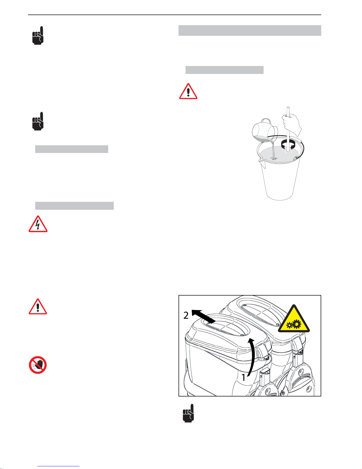
Diluire e miscelare in un recipiente il CONCENTRATO con ACQUA secondo le
indicazioni del produttore. LA MISCELA OTTENUTA DEVE AVERE UN CONTENUTO MINIMO DI ZUCCHERO DI 13° BRIX - Una minor concentrazione
può danneggiare le coclee miscelatrici e/o i motoriduttori stessi.
NON USARE MAI SOLO ACQUA
ACQUA
Per togliere il coperchio dalla vasca agire come segue:
1 sollevare il coperchio nella parte posteriore;
2 sfi lare il coperchio dal fermo situato nella parte anteriore.
Attenzione: non forzare l’apertura del coperchio nel caso sia
diffi coltosa.
Fig.7
Page 11
SL310005700 Ed.00 - 04-2011 - 9 _IT-
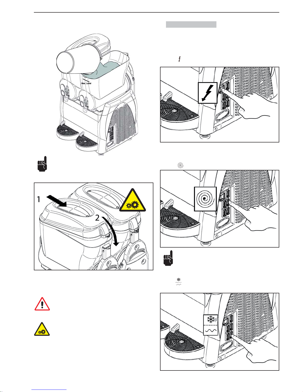
Versare il prodotto nella vasca facendo attenzione a non superare il livello Max indicato.
NON INTRODURRE LIQUIDI CALDI
(con temperatura maggiore di 25°C)
Dopo aver versato il prodotto nella vasca, chiudere quest’ultima con il coperchio.
Attenzione: non mettere in funzione la macchina se manca il
coperchio sualla vasca. Prima di togliere il coperchio, spegnere
la macchina e togliere la spina dalla presa di corrente.
Attenzione: all’interno della vasca ci sono degli organi in movimento che possono provocare delle lesioni; spegnere la macchina e staccare la spina dalla presa di corrente prima d’inter-
venire all’interno della vasca.
6.2. Avvio Granitore
Per semplicità sarà mostrato come azionare la sola vasca destra; per azionare
le altre vasche è suffi ciente compiere la medesima sequenza d’operazioni sugli
interruttori della vasca interessata.
Interruttore
in posizione “I” : macchina in tensione.
Ogni vasca è comandata da un interruttore ed un deviatore che devono essere
azionati come segue:
Interruttore
in posizione “I”: miscelatore in funzione.
Se la macchina è provvista di temporizzatore consultare il paragrafo 6.7 per una corretta impostazione della macchina.
Per ottenere una GRANITA:
Deviatore
: in pos. "I" impianto frigo in funzione (granita).
Fig.8
Fig.9
Fig.10
Fig.11
Fig.12
Page 12
- 10 _IT- SL310005700 Ed.00 - 04-2011
Per ottenere una BIBITA FREDDA:
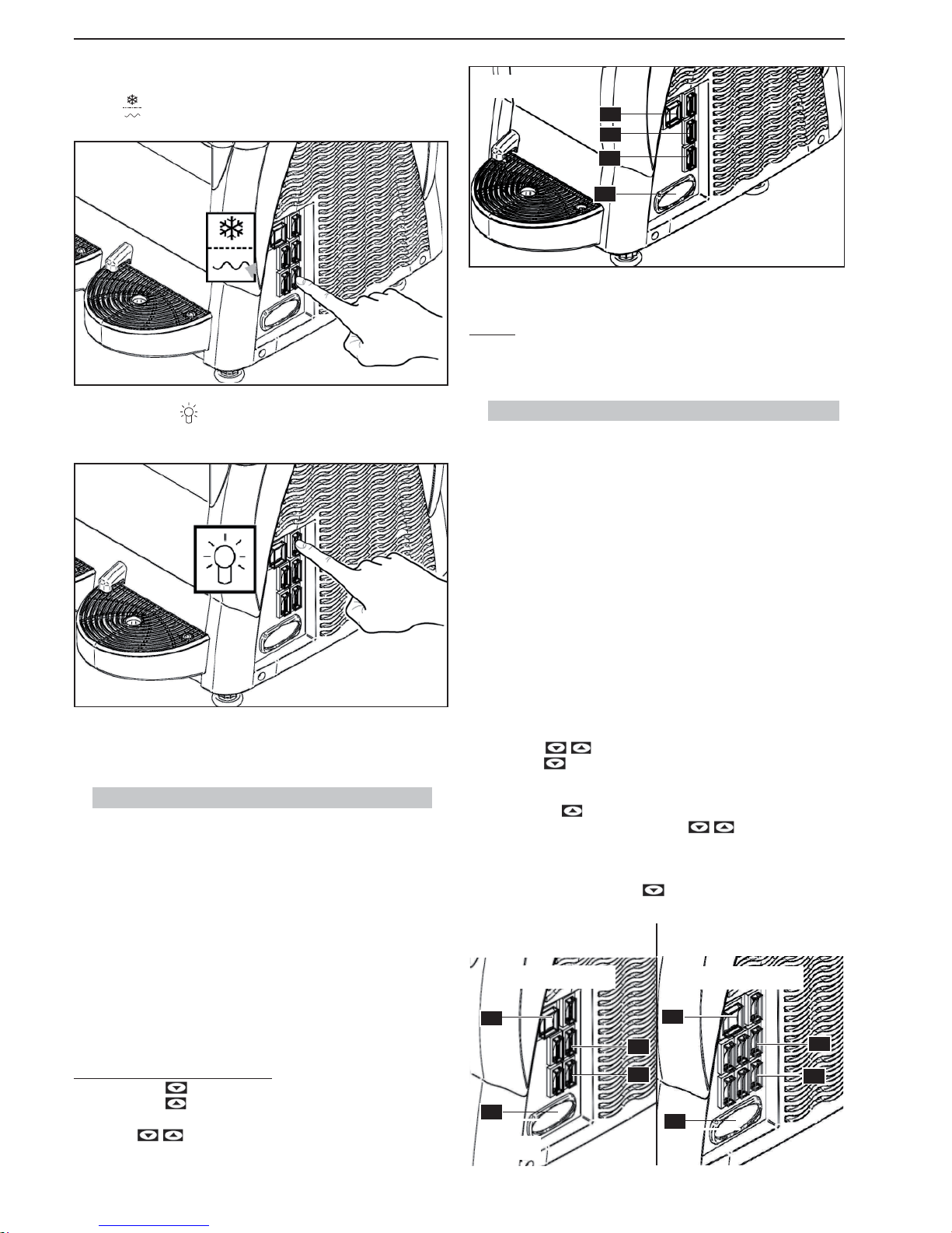
Deviatore
: in pos. "II" impianto frigo in funzione (bibita).
Premere l’interruttore
illuminazione coperchio per accendere il coperchio
luminoso presente nella macchina.
6.3. Avvio Granitore 1 (Termostato elettronico)
Il visualizzatore di temperatura ha la funzione di visualizzare la temperatura del
prodotto in vasca e regolarla quando la macchina è in funzione “frigo bibita”.
Interruttore (A) in posizione “I“: Macchina in tensione.
Interruttore (C) in posizione “I“: Miscelatore in funzione.
Per ottenere una GRANITA:
Interruttore (D) in posizione “I“: Impianto frigo in funzione (granita).
Per ottenere una BIBITA FREDDA:
Interruttore (D) in posizione “II“: Impianto frigo in funzione (bibita).
Per disabilitare il FRIGO (solo agitazione):
Deviatore (D) in posizione “0“: Impianto frigo disabilitato (solo agitazione).
Impostazione del set-point di temperatura
- Premere il tasto
Il display visualizza PrG.
- Premere il tasto
Il display visualizza il valore del set-point di temperatu-
ra.
-
Con i tasti è possibile variare il valore di set-point da 0°C ÷ 10° C.
Dopo 3 secondi dalla pressione dell’ultimo tasto il dato è memorizzato e il display visualizza la temperatura del prodotto in vasca.
ALLARMI
In caso di sonda guasta il display visualizza la scritta A1.
L’uscita di regolazione e la programmazione sono disabilitati.
6.4. Avvio Granitore 2/3 (Termostato elettronico)
Per semplicità sarà mostrato come azionare la sola vasca destra; per azionare
le altre vasche è suffi ciente compiere la medesima sequenza di operazioni sugli
interruttori della vasca interessata.
Interruttore (A) in posizione “I“: Machina in tensione.
Interruttore (C) in posizione “I“: Miscelatori in funzione.
Per ottenere una GRANITA:
Deviatori (D) in posizione “I“: Impianto frigo in funzione (granita).
Per ottenere una BIBITA FREDDA:
Deviatori (D) in posizione “II“: Impianto frigo in funzione (bibita).
Per disabilitare il FRIGO (solo agitazione):
Deviatori (D) in posizione “0“: Impianto frigo disabilitato (solo agitazione).
Impostazione del set-point di temperatura
- Con il termostato elettronico abilitato (acceso), premere contemporaneamente i tasti
il display visualizza “t1”.
- Con il tasto
è possibile scorrere i set-point “t1”; “t2” (Macchina 2 va-
sche), “t1”; “t2”; “t3” (Macchina 3 vasche).
- Quando il display visualizza il set-point che si vuole variare (“t1”o “t2” o “t3”),
premere il tasto
per visualizzare il valore del set-point.
- E’ quindi possibile modifi care tramite i tasti
il valore di set-point da
0°C ÷ 10°C.
• Dopo tre secondi dalla pressione dell’ultimo tasto il dato è memorizzato.
Il display torna a visualizzare “t1”o “t2” o “t3” a seconda del set-point che
si è modifi cato. Premere il tasto
fi no a quando il display visualizza la
temperatura del prodotto in vasca.
Fig.13
Fig.14
A
C
D
E
Fig.15
2 VASCHE
3 VASCHE
A
E
D
C
E
A
C
D
Fig.16
Page 13
SL310005700 Ed.00 - 04-2011 - 11 _IT-
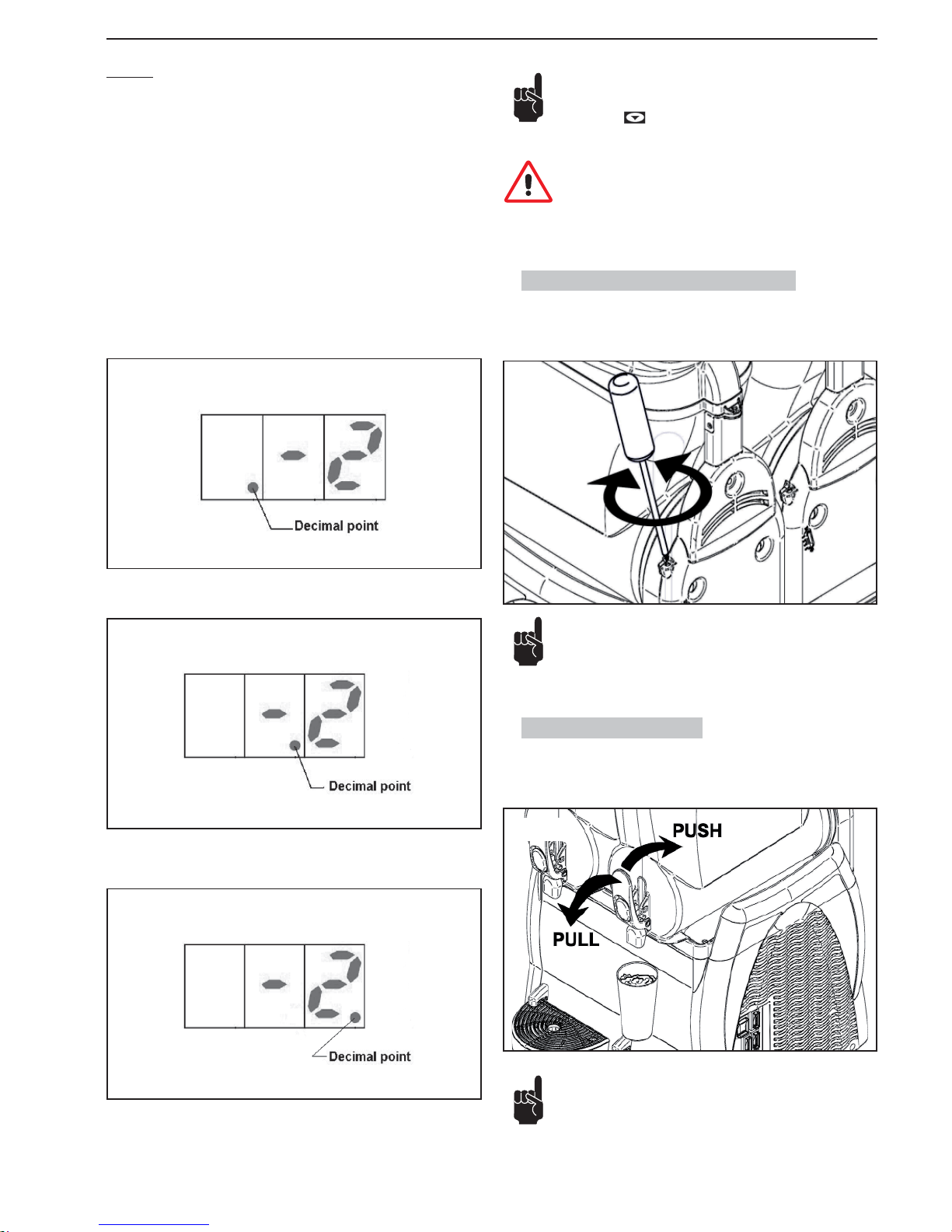
6.5. Regolazione consistenza granita
É possibile variare la consistenza della granita (+/-) registrando la vite indicata
nel disegno +: maggiore consistenza, -: minore consistenza.
6.6. Erogazione granita
Per prelevare la bevanda agire sulla leva del rubinetto.
La regolazione può essere eseguita manualmente o con l’utilizzo di un cacciavite idoneo a taglio.
ALLARMI
In caso di sonda guasta il display visualizza i seguenti messaggi di allarme:
“A1”: Sonda vasca 1 scollegata
“A2”: Sonda vasca 1 in corto circuito
“A3”: Sonda vasca 2 scollegata
“A4”: Sonda vasca 2 in corto circuito
“A5”: Sonda vasca 3 scollegata
“A6”: Sonda vasca 3 in corto circuito
Durante il funzionamento, il termostato elettronico visualizza la temperatura del
prodotto nelle vasche mostrando ciclicamente ogni 3 secondi la temperatura
del prodotto di una vasca e poi dell’altra.
Per capire a quale vasca si riferisce la temperatura visualizzata dal termostato
elettronico bisogna fare riferimento a quale decimal point è visualizzato.
Se il decimal point visualizzato è a sinistra, la temperatura indicata si riferisce
alla vasca 1 (Vedi Fig.2 Pagina 4).
Se il decimal point visualizzato è centrale, la temperatura indicata si riferisce
alla vasca 2 (Vedi Fig.2 Pagina 4).
Se il decimal point visualizzato è a destra, la temperatura indicata si riferisce
alla vasca 3 (Vedi Fig.2 Pagina 4).
Fig.18
2 VASCHE
Fig.19
3 VASCHE
Fig.17
Nota: Se durante l’utilizzo della macchina inavvertitamente si
dovesse spegnere il termostato elettronico, per riattivarlo premere il tasto
. Se il termostato elettronico non si dovesse
più riattivare, spegnere la macchina e rivolgersi al centro assistenza.
Attenzione: Durante l’utilizzo della macchina, il termostato elettronico deve essere sempre attivo in modo da visualizzare sempre la temperatura del prodotto nelle vasche.
Controllare periodicamente la temperatura del prodotto in vasca con un termometro campione per verifi care che il prodotto
sia sempre al di sotto della temperatura di conservazione. Per i
modelli macchina equipaggiati di visualizzatore di temperatura
o termostato elettronico, verifi care inoltre che la temperatura del
prodotto, rilevata con termometro campione, corrisponda alla
Fig.20
Fig.21
Page 14
- 12 _IT- SL310005700 Ed.00 - 04-2011
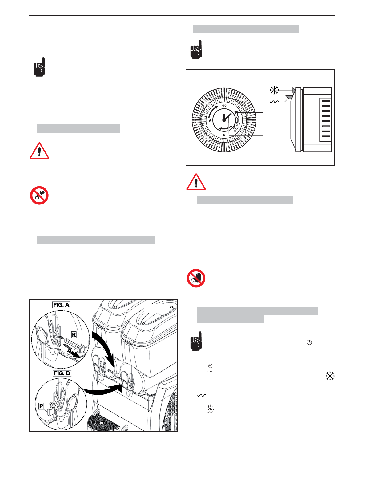
6.9. Acc. opzionali (Temporizzatore)
Il temporizzatore mostrato è indicativo.
A
B
C
Fig.23
Le impostazioni del temporizzatore devono essere eseguite con
l’interruttore generale sulla posizione -0- e con la spina disinserita dalla presa di corrente.
6.9.1. Impostazione ora corrente
Prima di cominciare ad utilizzare il temporizzatore si deve regolare il giorno e
l’ora corrente.
Per eseguire la regolazione ruotare il quadrante del timer nel senso indicato
dalla freccia fi no a quando l’indicatore (A) non indica il giorno esatto, dopo pro-
seguire ruotando la lancetta (C) fi no a raggiungere l’ora corrente.
É vietato:
• ruotare la lancetta con qualsiasi strumento;
• ruotare la lancetta in senso inverso a quello mostrato nel
temporizzatore.
6.9.2. Funzionamento della macchina con
temporizzatore
In tutte le macchine provviste di temporizzatore si deve verifi ca-
re che il selettore (B) sia sulla posizione centrale
.
La macchina deve essere avviata come mostrato nel paragrafo 6.2.
Deviatore
in posizione “I”:
- per ottenere granita posizionare il cavaliere del timer in posizione
nel giorno e ora desiderata;
- per ottenere bibita fredda posizionare il cavaliere del timer in posizione
nel giorno e ora desiderata.
Deviatore
in posizione “II”:
la macchina esclude il timer e funziona solamente in frigobibita.
temperatura visualizzata dalla macchina. Con il prodotto in vasca ancora da consumare, non togliere mai l’alimentazione alla
macchina e non spegnere mai l’interruttore generale lasciando
sempre la macchina accesa in funzione granita o frigobibita.
Se la macchina non viene utilizzata con continuità, in caso di prodotti a base latte, occorre:
- Spruzzare soluzione sanitizzante sull’area del rubinetto e sul
rubinetto stesso (in alternativa di lavare con panno pulito e sanitizzante);
oppure:
- Prelevare una piccola quantità di prodotto dal rubinetto prima
di erogare la dose per il cliente.
6.7. Situazioni d’emergenza
ATTENZIONE: in ogni situazione d’emergenza, per fermare la
macchina, premere con decisione l’interruttore generale sulla
posizione -0-.
In caso di congelamento spegnere la macchina e rivolgersi al centro assistenza o a un tecnico specializzato.
In caso d’incendio si deve immediatamente sgombrare la zona
per permettere l’intervento di personale addestrato e dotato di
mezzi di protezione idonei. Utilizzare sempre estintori omologati, non utilizzare mai acqua o sostanze di incerta natura.
6.8. Acc. opzionali (Sistema di Chiusura)
Usare il nuovo sistema di blocco rubinetto nel modo seguente:
Fig. A: Mentre state usando la macchina, posizionare il perno “R” come
illustrato nella fi gura.
Fig. B: Per bloccare la maniglia, inserire il perno “R” nel suo foro e posi-
zionare il lucchetto come nella fi gura.
Fig.22
Page 15
SL310005700 Ed.00 - 04-2011 - 13 _IT-
7. PULIZIA E MANUTENZIONE
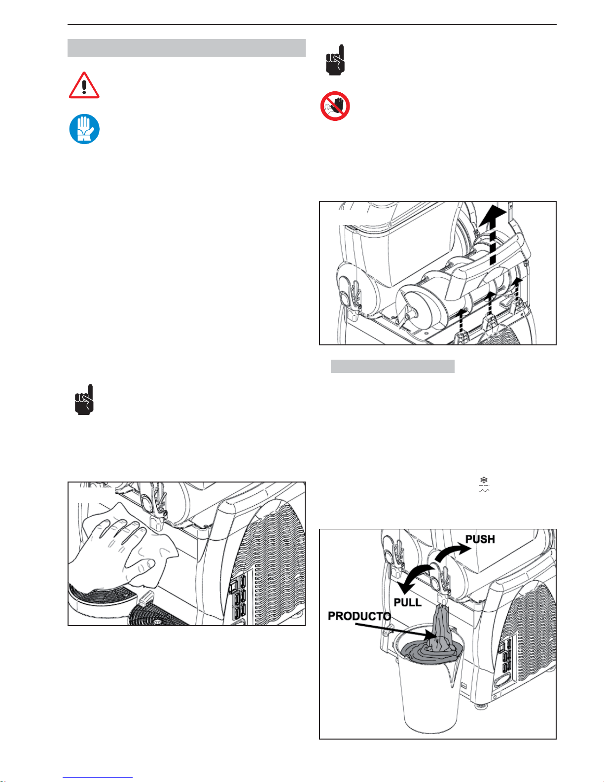
La pulizia e la manutenzione dei componenti esterni della macchina deve essere eseguita con l’interruttore generale sulla posizione -0- e con la spina disinserita dalla presa di corrente.
Prima d’eseguire qualsiasi operazione inerente la pulizia e la
manutenzione della macchina, indossare le protezioni personali (guanti, occhiali, ecc..) che sono stabilite dalle normative di
sicurezza vigenti nel paese d’utilizzo della macchina.
Nell’effettuare i lavori di Pulizia o Manutenzione, applicare quanto di seguito
descritto:
• indossare guanti antinfortunistici di protezione;
• non utilizzare solventi e materiali infi ammabili;
• non utilizzare spugne abrasive e/o metalliche per la pulizia della macchina e
dei suoi componenti;
• prestare attenzione a non disperdere nell’ambiente liquidi;
• non lavare i componenti della macchina nella lavastoviglie;
• non utilizzare un forno convenzionale e/o a microonde per asciugare parti
della macchina;
• non immergere la macchina nell’acqua;
• non spruzzare sulla macchina getti d’acqua diretti;
• per la pulizia utilizzare esclusivamente acqua tiepida e un sanitizzante idoneo (conforme alle normative vigenti nel paese d’utilizzo) e tale da non danneggiare i componenti della macchina;
• alla fi ne dei lavori, ripristinare e fi ssare correttamente tutte le protezioni e i
ripari rimossi o aperti.
La pulizia e la sanitizzazione sono operazioni che si devono compiere abitualmente con la massima cura per garantire la qualità della produzione ed in rispetto delle norme igieniche necessarie.
La pulizia e la sanitizzazione della vasca deve essere eseguita
almeno una volta al giorno e in ogni caso nel rispetto delle
norme igieniche vigenti nel paese d’utilizzo. Queste operazioni
devono essere eseguite più frequentemente nel caso un cui le caratteristiche del prodotto utilizzato lo richiedano; per maggiori dettagli consultare
il fornitore del prodotto. Nel caso la macchina non venga usata con continuità durante la giornata, lavare con panno pulito e soluzione sanitizzante
la zona del rubinetto e il condotto di uscita del prodotto, come indicato
nella fi gura sottostante.
I materiali inossidabili, i materiali plastici, le gomme usate nella
costruzione di dette parti e la loro particolare forma agevolano
la pulizia, ma non impediscono la formazione di batteri e muffe
in caso di pulizia insuffi ciente.
É vietato pulire o eseguire la manutenzione della macchina con
l’interruttore generale sulla posizione -1- e con la spina inserita
nella presa di corrente.
Nel caso fosse necessario, per procedere alla manutenzione ed alla pulizia
della macchina, si possono smontare le parti superiori dei carter laterali. Per
estrarli, sollevare con decisione la parte superiore. Quando terminato reinserire
la parte nel carter laterale.
7.1. Svuotamento vasche
Prima di procedere con la pulizia di ogni vasca è necessario svuotarla del prodotto che è stato precedentemente preparato.
Nel caso si proceda alla pulizia antecedente il primo utilizzo, non occorre
svuotare la vasca; consultare subito il paragrafo 7.2.
Per semplicità sarà mostrato come svuotare la sola vasca destra; per azionare le altre vasche è suffi ciente compiere la medesima sequenza d’operazioni
agendo sui comandi della vasca interessata.
Il procedimento sotto elencato è valido sia per i modelli con e senza termostato
elettronico.
Con la macchina accesa, portare il deviatore frigo
su "O" e svuotare la
vasca da tutto il prodotto che è presente all’interno.
Fig.24
Fig.26
Fig.25
Page 16
- 14 _IT- SL310005700 Ed.00 - 04-2011
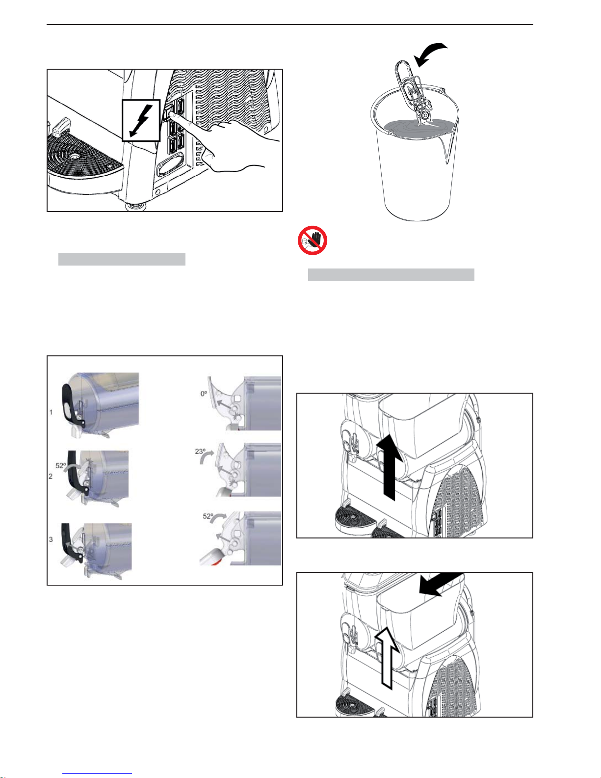
É vietato smontare il rubinetto se all’interno della vasca è presente il prodotto o un qualsiasi altro liquido.
7.3. Smontaggio vasca e coperchio
Lo smontaggio di ogni vasca presente nella macchina è fondamentale per la
corretta pulizia e sanitizzazione della macchina.
Per smontare correttamente una vasca procedere come segue:
1 rimuovere il coperchio come mostrato nel paragrafo 6.1.
2 togliere la vasca sollevando la parte anteriore fi no al suo sganciamento;
Successivamente spegnere l’interruttore miscelatore e l’interruttore generale;
togliere la spina dalla presa di corrente.
7.2. Smontaggio rubinetto
Prima d’iniziare a smontare la vasca si consiglia di procedere con lo smontaggio del rubinetto; successivamente il rubinetto dovrà essere rimontato solo
dopo aver correttamente posizionato la vasca.
Smontare il rubinetto togliendo i perni de le sue sedi. Per ciò premere la leva
push del rubinetto fi no a fare battuta con la vasca come indicato nella fi gura.
Dopo tirare del rubinetto verso l´alto fi no disincastrare i perni.
I componenti possono essere depositati in una bacinella con acqua calda (circa
50°C); dopo dovranno essere trattati come descritto nel par.7.4.
3 spingendo sulla parte posteriore, con l’aiuto di piccoli colpi, fare uscire la
vasca dalla propria sede;
4 sfi lare la coclea e togliere le guarnizioni (A) e (B).
Fig.27
Fig.28
Fig.29
Fig.30
Fig.31
Page 17
SL310005700 Ed.00 - 04-2011 - 15 _IT-
7.4. Lavaggio e sanitizzazione componenti
Tutti i componenti precedentemente smontati devono essere accuratamente
lavati e sanitizzati .
Attenzione: la soluzione sanitizzante deve essere conforme con
le norme vigenti al momento dell’utilizzo della macchina.
Per eseguire correttamente questa procedura, procedere come segue:
1 Riempire un recipiente con una soluzione sanitizzante preparata in acqua
(ipoclorito di sodio in quantità del 2% in soluzione con acqua)
2 Lavare accuratamente la vasca, il coperchio e l’evaporatore con una spugna
imbevuta di soluzione sanitizzante
3 Risciacquare abbondantemente con acqua pulita
4 Riempire un altro recipiente con la soluzione sanitizzante
5 Immergere i componenti smontati nella soluzione sanitizzante
6 Lasciare in ammollo i componenti smontati nella soluzione sanitizzante per
30 minuti
7 Risciacquare abbondantemente con acqua pulita
8 Porre i componenti su un piano pulito e asciugarli
9 Riassemblare la macchina come descritto al par. 7.5
10 Prima di riutilizzare la macchina effettuare un ciclo di risciacquo della mac-
china con acqua pulita (vedi par. 7.6)
Attenzione: non immergere in qualsiasi liquido i coperchi provvisti d’illuminazione. Prima d’eseguire le operazioni di pulizia e
sanitizzazione del coperchio, smontarlo dalla macchina come
descritto nel capitolo precedente.
Per una corretta pulizia del coperchio luminoso procedere come segue;
1. Pulire con un panno pulito e umido prima la parte inferiore del coperchio (a
contatto con il prodotto);
2. Pulire con un panno pulito e umido tutta la parte esterna;
Fig.35
Fig.34
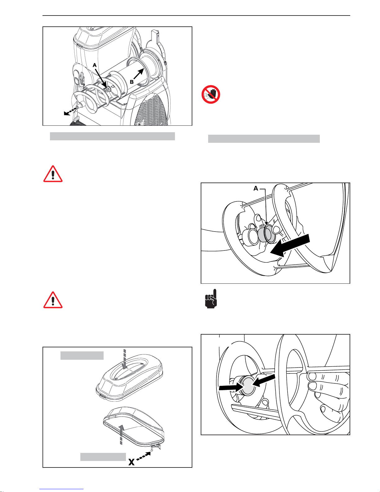
7.5. Assemblaggio componenti lavati.
Tutti i componenti lavati e sanitizzati devono essere riassemblati con cura.
Alcuni componenti devono essere opportunamente lubrifi cati per garantire il
loro corretto funzionamento.
Installare la guarnizione (A) sulla coclea come mostrato in fi g.34.
Nota importante: verifi care sempre l’integrità della guarnizione,
nel caso sia usurata, sostituirla con una nuova.
Si deve sostituire la guarnizione (A) almeno una vota all’anno.
Lubrifi care la guarnizione (A) nelle zone mostrate in fi g.35 con la vaselina for-
nita in dotazione.
3. Utilizzando una spugna imbevuta di sanitizzante, sanitizzare la parte inferiore del coperchio, avendo cura di non bagnare i contatti (X);
4. Lasciare agire per 30 minuti;
5. Risciacquare, solo la parte inferiore, due o più volte con una spugna pulita
imbevuta di acqua fresca.
6. Porre il coperchio su un piano pulito e asciugarlo; asciugare, con un panno
pulito, prima la parte inferiore e poi l’esterno.
7. Riposizionare il coperchio solo dopo aver eseguito la pulizia e la sanitizzazione della vasca.
É vietato lavare e/o sanitizzare il coperchio quando è installato
sulla macchina.
Fig.32
Fig.33
Parte esterna
Parte inferiore
Page 18
- 16 _IT- SL310005700 Ed.00 - 04-2011
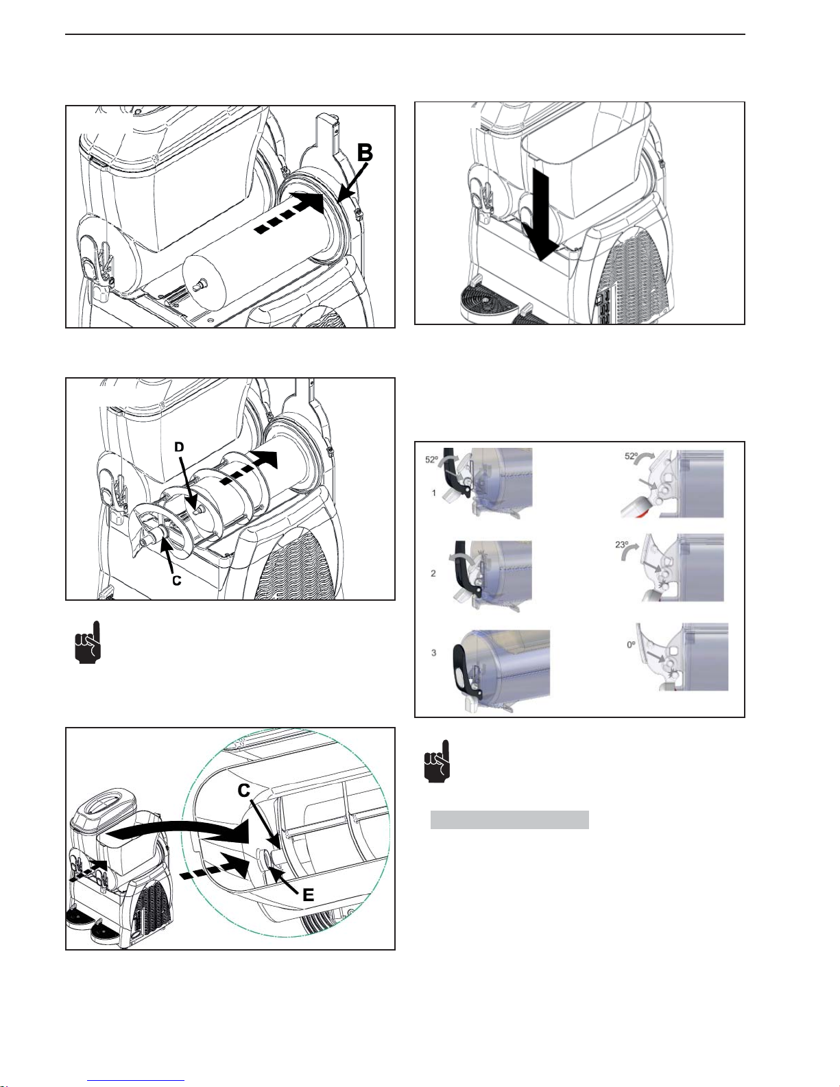
Installare la guarnizione (B) lubrifi candola con vaselina su tutta la superfi cie
indicata dalle frecce.
Introdurre la coclea facendo agganciare la testina (C) con l’albero (D).
Nota: l’aggancio della coclea si ottiene ruotandola.
Posizionare la vasca nella sua sede;
sollevare leggermente la testina (C) della
coclea facendola congiungere con la sede (E) della vasca.
Per montare il rubinetto procedere come segue:
1 lubrifi care in modo idoneo il tappo con la vaselina fornita a corredo e rias-
semblare i componenti;
2 attacare i perni sulle sue sede e premere la leva push fi no adattarsei al
rubinetto, come illustrato di seguito
Premere la vasca in basso fi no al suo aggancio con il piano come mostrato in
fi gura.
Nota: installare correttamente i componenti come mostrato in
fi gura. La mancata lubrifi cazione del tappo può provocare la
fuoriuscita di prodotto dal rubinetto.
7.6. Ciclo di risciacquo
Prima di procedere con l’avvio della macchina, si deve procedere col ciclo di
risciacquo.
Operare come segue:
1. Riempire la vasca di acqua pulita.
2. Lasciare accesa la macchina per 5 minuti con la sola funzione agitazione.
3. Spegnere la macchina e svuotare la vasca tramite il rubinetto.
Fig.36
Fig.37
Fig.38
Fig.39
Fig.40
Page 19
SL310005700 Ed.00 - 04-2011 - 17 _IT-
7.7. Pulizia vasca raccogli gocce
Giornalmente si deve procedere con lo svuotamento e la pulizia della vaschetta
raccogli gocce.
Nota: le operazioni di pulizia devono essere eseguite su tutte le
vaschette presenti nella macchina.
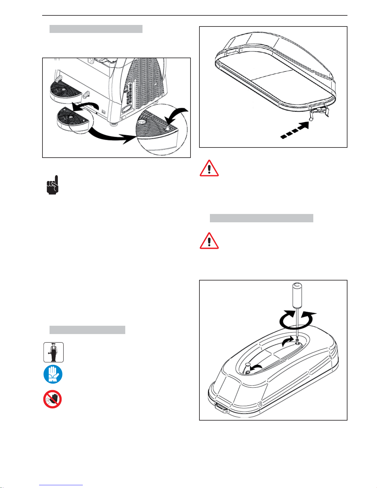
La vaschetta deve essere svuotata e pulita ogni qualvolta si solleva il galleggiante rosso installato nella griglia.
Sollevare la vaschetta con la griglia ed estrarla dalla propria sede tirandola
verso l’esterno.
Lavare la vaschetta e la griglia separatamente con acqua tiepida.
Asciugare tutti i componenti.
Riposizionare la griglia sopra la vaschetta.
Posizionare il tubo di scarico nell’apposita feritoia.
Inserire la vaschetta nella sua sede e premerla verso il basso per renderla
solidale con la macchina.
7.8. Coperchio luminoso
La manutenzione del coperchio luminoso è di esclusiva competenza del tecnico specializzato che dovrà organizzare tutte
le sequenze operative e l’impiego di mezzi adeguati ad operare nel rigoroso rispetto delle norme vigenti in materia.
Per l’operatore è vietato smontare qualsiasi componente del
coperchio.
Pulire i contatti del coperchio con un panno umido e asciugare bene, questa
operazione va eseguita sempre a macchina spenta.
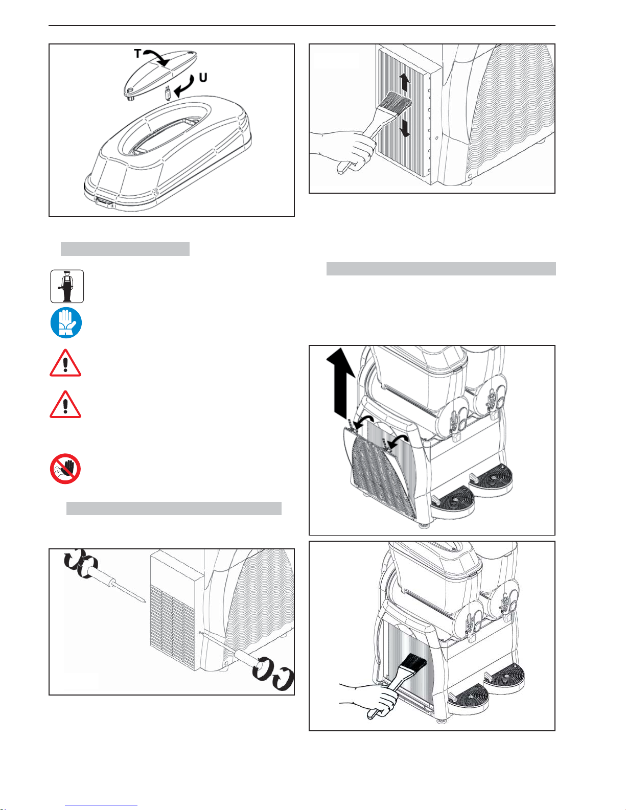
Togliere la lampadina “U” dal portalampada “T” e sostituirla con quella nuova.
Riassemblare il coperchio e avvitare le due viti.
7.8.1. Sostituzione della lampadina
La sostituzione della lampadina deve essere eseguita con l’interruttore generale sulla posizione -0- e con la spina disinserita.
Togliere i tappi di protezione; separare le due parti del coperchio luminoso
svitando le due viti; per eseguire questa operazione utilizzare un cacciavite
idoneo.
Attenzione: durante le operazioni di pulizia, fare attenzione a
non danneggiare (piegare, rompere, ecc...) i contatti; in caso di
danneggiamento si può avere un malfunzionamento del coperchio non coperto da garanzia.
Fig.41
Fig.43
Fig.42
Page 20
- 18 _IT- SL310005700 Ed.00 - 04-2011
7.9.1. Pulizia condensatore Granitore 1 - 1FF
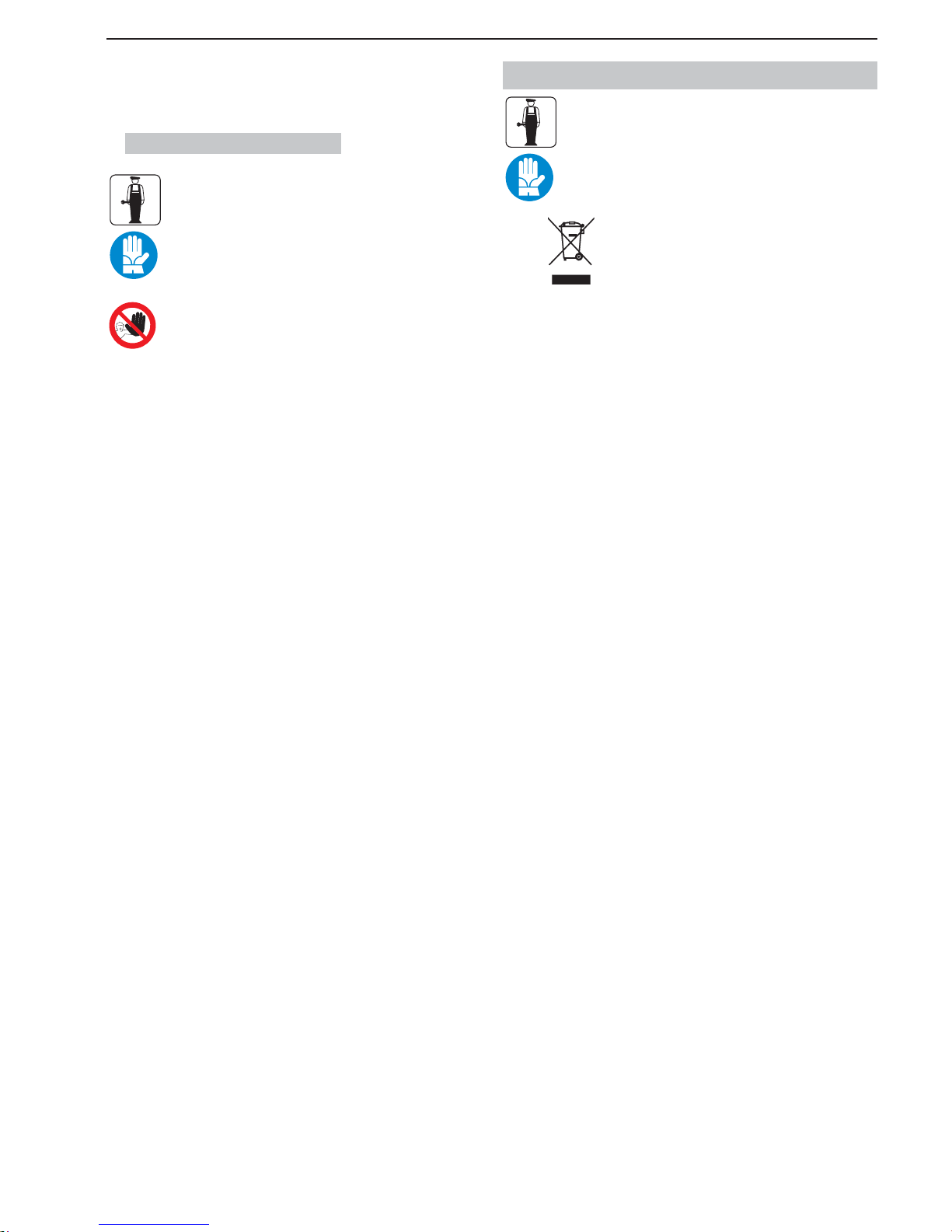
I carter devono essere smontati utilizzando un cacciavite idoneo.
Rimuovere il carter posteriore dopo aver svitato le viti che lo fi ssano al telaio (le
viti sono posizionate sul lato destro e sinistro).
Dopo aver rimosso il carter, con un pennello secco, rimuovere la polvere che si
è accumulata nel corso del normale funzionamento.
Fig.45
7.9. Pulizia condensatore
La pulizia del condensatore è di esclusiva competenza del
tecnico specializzato che dovrà organizzare tutte le sequenze
operative e l’impiego di mezzi adeguati ad operare nel rigoroso rispetto delle norme vigenti in materia.
Effettuare una pulizia periodica del condensatore che si trova all’interno della macchina.
Attenzione: rimuovendo i carter si accedono ad alcune superfi -
ci taglienti della macchina.
Un condensatore sporco compromette il buon funzionamento
della macchina.
Per accedere al condensatore rimuovere i carter di protezione.
L’utilizzo della macchina è vietato quando anche un solo pannello (frontale, posteriore o laterale) non sia adeguatamente
montato. La pulizia del condensatore è vietata all’operatore.
Dopo aver accuratamente pulito il condensatore, rimontare tutti i carter.
Fig.46
- Dopo aver rimosso le 4 viti sfi lare il carter.
Dopo aver rimosso il carter, con un pennello secco, rimuovere la polvere che si
è accumulata nel corso del normale funzionamento.
7.9.2. Pulizia condensatore Granitore 2-2FF-3-3FF
Per la rimozione del carter procedere come segue:
- Sollevare e rimuovere completamente la parte superiore del carter laterale;
- rilasciare le 2 schede contemporaneamente le pressanti e tirare fuori il pannello l, come illustrato di seguito:
Fig.44
Fig.47
Fig.48
Page 21
SL310005700 Ed.00 - 04-2011 - 19 _IT-
Dopo aver accuratamente pulito il condensatore, rimontare tutti i componenti
del carter.
7.10. Manutenzione periodica
La macchina deve essere periodicamente, almeno una volta
all’anno, verifi cata da un tecnico specializzato.
Questa verifi ca periodica serve a mantenere alto il livello di si-
curezza di tutti i componenti installati e della macchina stessa.
Nel caso un componente sia usurato, deve essere sostituito
con un ricambio originale nuovo.
L’utilizzo della macchina è vietato quando anche un solo componente sia difettoso o usurato. La manuatenzione periodica è
vietata all’operatore.
8. DEMOLIZIONE
Le apparecchiature elettriche ed elettroniche devono essere
smaltite secondo la Direttive Europea 2002/96/CE.
T ale apparecchiature NON possono essere smaltite secondo il normale fl usso dei rifi uti solidi urbani, ma devono essere raccolti se-
paratamente per ottimizzare il recupero e il riciclaggio dei materiali
con i quali sono costruiti.
Il simbolo
del cestino barrato è riportato su tutti i prodotti per ricordare
gli obblighi di raccolta separata. Osservando correttamente tutte le disposizioni riguardo lo smaltimento dei vecchi prodotti, si contribuirà a salvaguardare
l’ambiente.
Page 22
- 20 _IT- SL310005700 Ed.00 - 04-2011
9. PROBLEMI - CAUSE - RIMEDI
Problemi Cause Rimedi
La macchina non si accende. Interruttore generale spento (in posizione “O”). (Cap.6) Premere l’interruttore sulla posizione “I”.
Spina non inserita. Inserire la spina in una presa conforme.
Il rubinetto perde. Tappo rubinetto non lubrifi cato. (Fig.38) Lubrifi care tappo.
Tappo difettoso. Sostituire tappo.
Perdita prodotto nella parte posteriore della
vasca.
Vasca non correttamente montata. (Par.7.5) Verifi care il montaggio della vasca.
Guarnizione vasca non lubrifi cata. (Fig.34) Lubrifi care la vasca in modo corretto.
Guarnizione difettosa. Sostituire guarnizione.
La coclea non gira. Interruttore in posizione “O”. (Cap.6) Premere l’interruttore sulla posizione “I”.
Blocchi di ghiaccio all’interno della vasca. Spegnere la macchina, lasciare sciogliere il prodotto e
verifi care che il prodotto sia diluito correttamente.
La macchina non fa granita. Interruttore in posizione “O”. (Cap.6) Premere l’interruttore sulla posizione “I”.
Macchina vicina a fonti di calore. Installare in un luogo adatto. (Cap.5)
Macchina con insuffi ciente areazione.
Condensatore sporco. (Par.7.9) Chiamare il tecnico specializzato per eseguire un’ade-
guata pulizia del condensatore.
Errata regolazione della consistenza. (Par.6.4) Regolare correttamente la consistenza.
Cavalieri del temporizzatore in posizione “
”. Mettere i cavalieri in posizione “ ” vedi par.6.9
Coclea rumorosa. Guarnizione anteriore montata in modo errato. (Fig.32) Verifi care il corretto montaggio della guarnizione.
Guarnizione non lubrifi cata. (Fig.33) Lubrifi care in modo corretto la guarnizione.
Il rubinetto non eroga Blocchi di ghiaccio all’interno della vasca. Spegnere la macchina, lasciare sciogliere il prodotto e
verifi care che il prodotto sia diluito correttamente.
Se le cause del malfunzionamento della macchina non sono elencate nella presente tabella o se i rimedi proposti non risolvono il problema, contattare un tecnico
specializzato.
Page 23
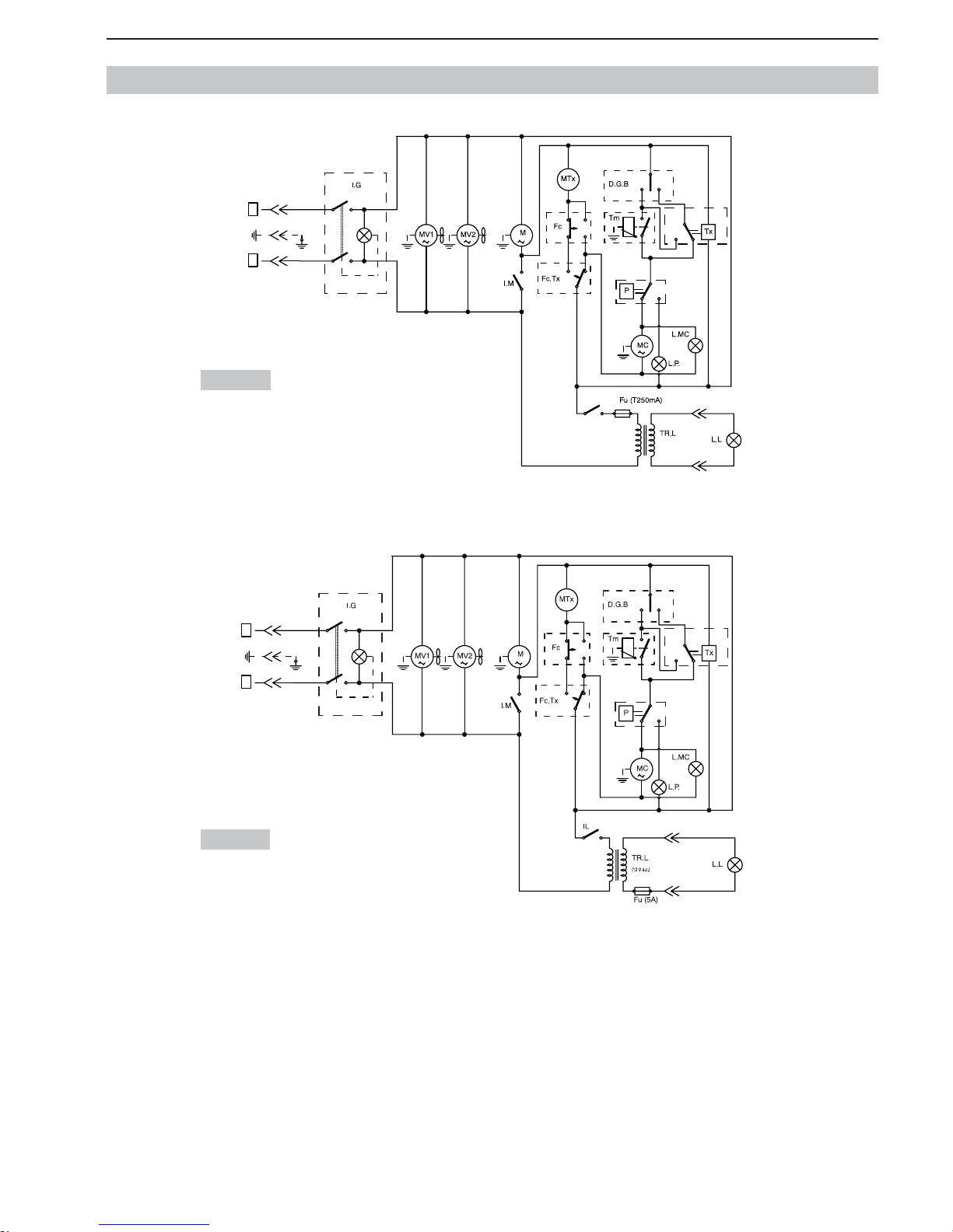
SL310005700 Ed.00 - 04-2011 - 21 _IT-
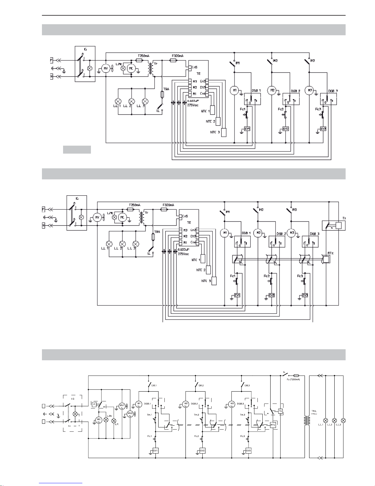
10. SCHEMI ELETTRICI DI PRINCIPIO (GRANITORE 1 - 1 FF)
230 Volt
115 Volt
0
I
I
0
IL
0
I
0
I
I0II
t°
F
N
(12 V a.c.)
0
I
I
0
0
I
0
I
I0II
t°
F
N
Page 24
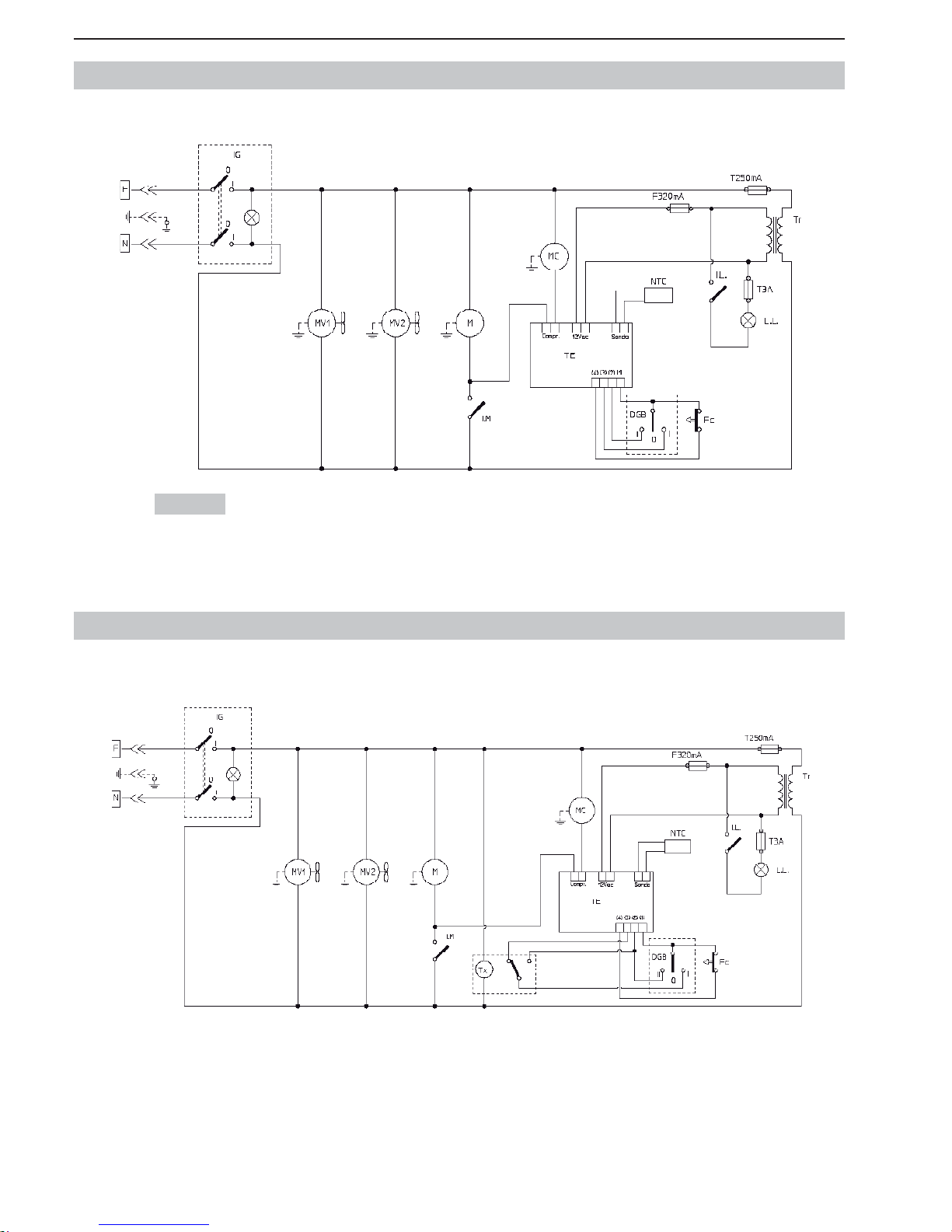
- 22 _IT- SL310005700 Ed.00 - 04-2011
SCHEMI ELETTRICI DI PRINCIPIO (GRANITORE 1 - 1 FF CON TERMOSTATO)
SCHEMI ELETTRICI DI PRINCIPIO (GRANITORE 1 - 1 FF CON TERMOSTATO + TIMER)
230 Volt
Page 25
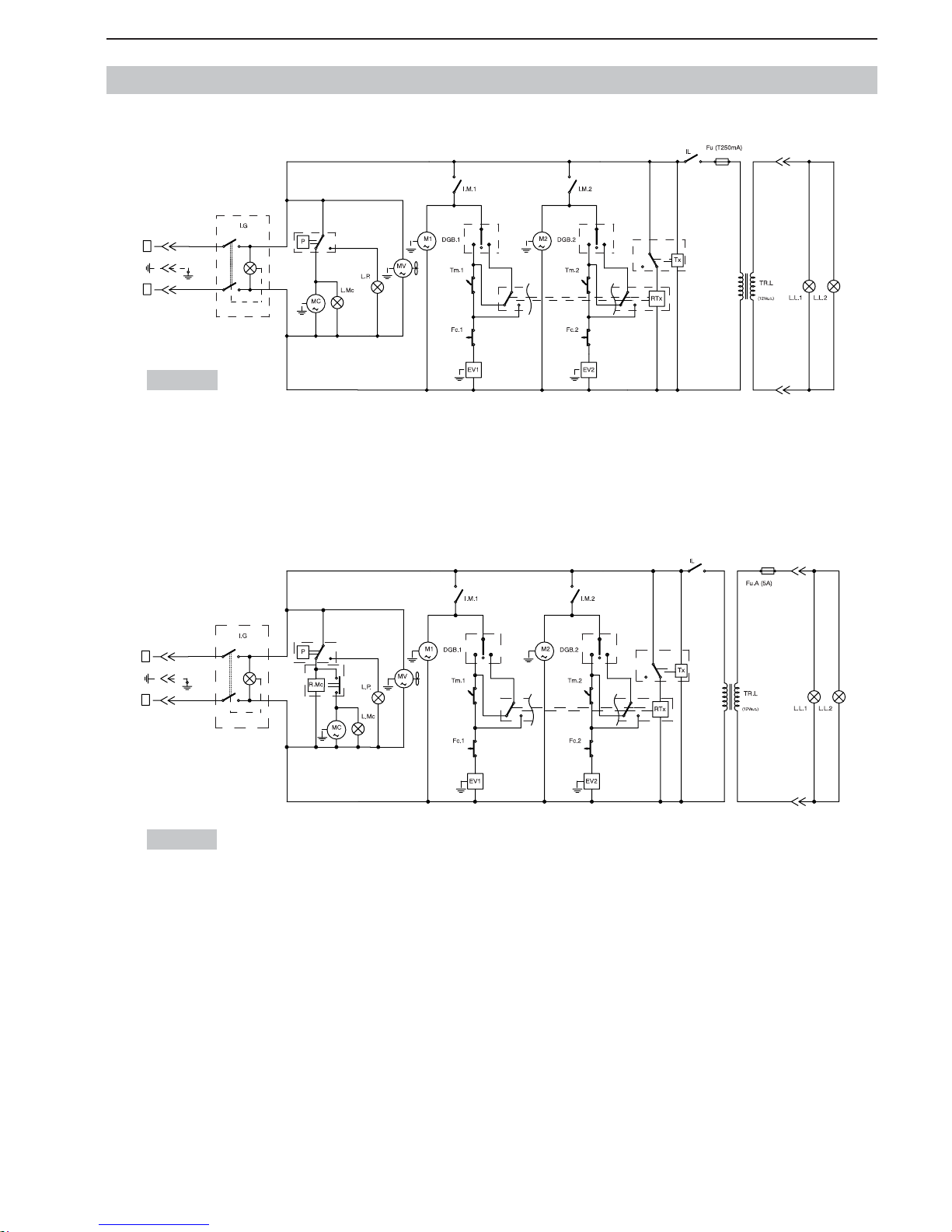
SL310005700 Ed.00 - 04-2011 - 23 _IT-
SCHEMI ELETTRICI DI PRINCIPIO (GRANITORE 2 - 2FF)
230 Volt
115 Volt
IIIIII
I
0
0
I
0
I
I
0
F
N
IIIIII
I
0
0
I
0
I
I
0
F
N
Page 26
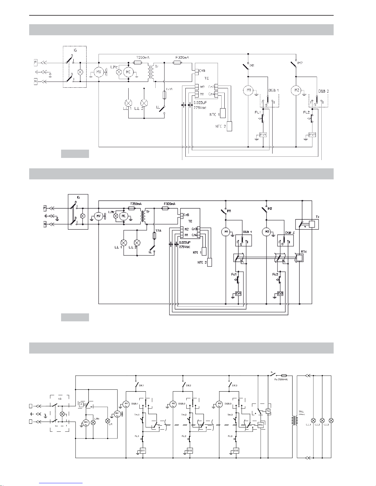
- 24 _IT- SL310005700 Ed.00 - 04-2011
SCHEMI ELETTRICI DI PRINCIPIO (GRANITORE 3) / 230V
I
0
III IIIIII
I
0
0
I
0
I
I
0
F
N
SCHEMI ELETTRICI DI PRINCIPIO (GRANITORE 2 - 2 FF CON TERMOSTATO)
SCHEMI ELETTRICI DI PRINCIPIO (GRANITORE 2 - 2 FF CON TERMOSTATO + TIMER)
230 Volt
230 Volt
Page 27
SL310005700 Ed.00 - 04-2011 - 25 _IT-
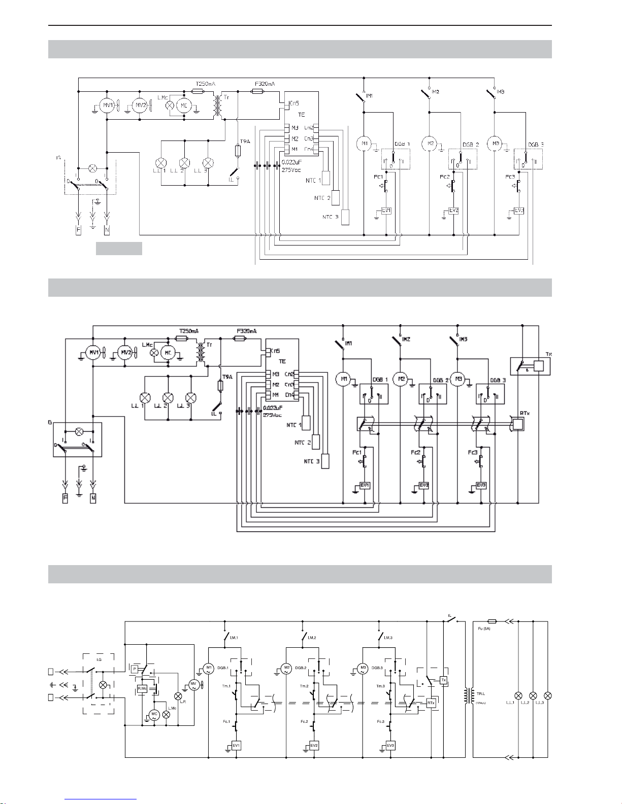
SCHEMI ELETTRICI DI PRINCIPIO (GRANITORE 3FF) / 230V
I
0
III IIIIII
I
0
0
I
0
I
I
0
F
N
SCHEMI ELETTRICI DI PRINCIPIO (GRANITORE 3 CON TERMOSTATO)
SCHEMI ELETTRICI DI PRINCIPIO (GRANITORE 3 CON TERMOSTATO + TIMER)
230 Volt
Page 28
- 26 _IT- SL310005700 Ed.00 - 04-2011
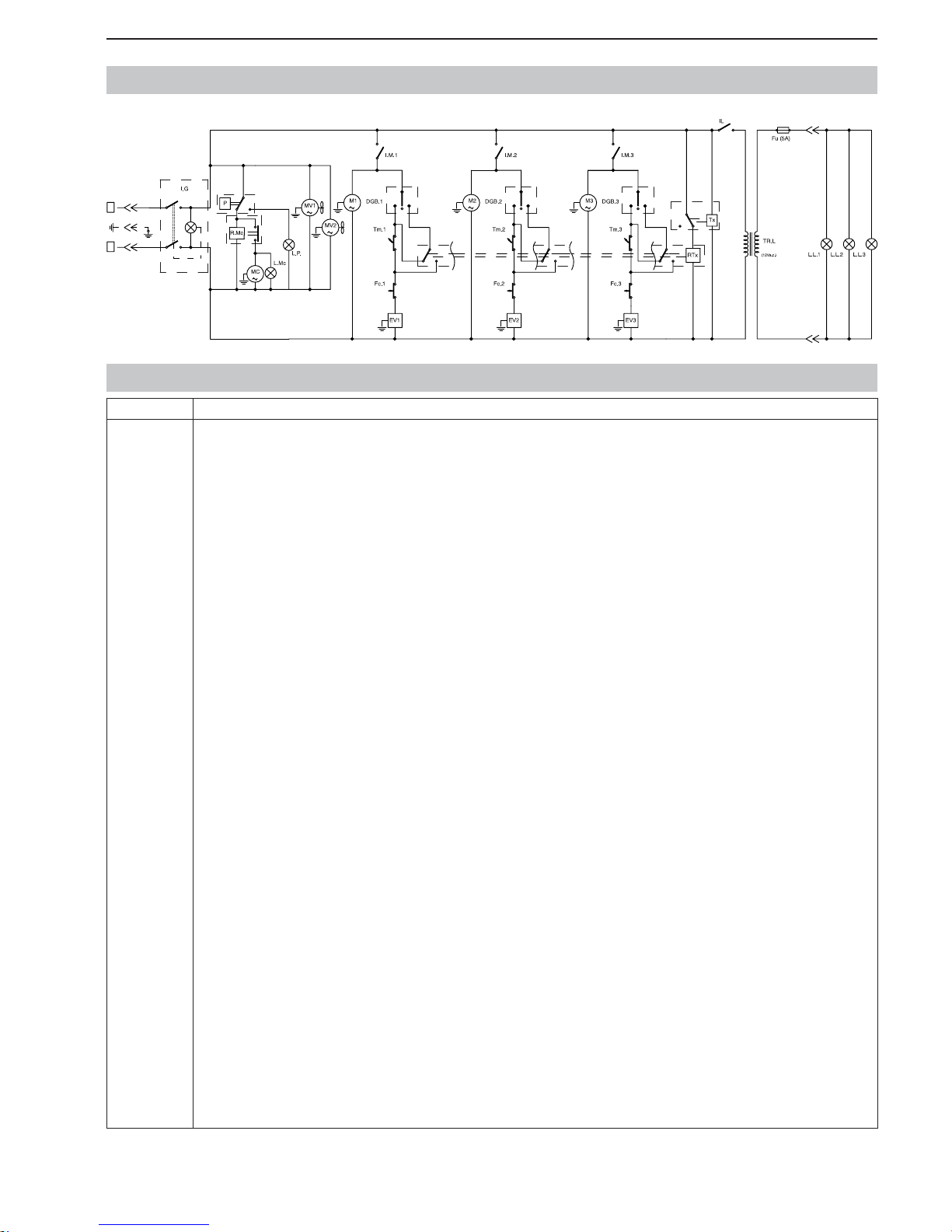
SCHEMI ELETTRICI DI PRINCIPIO (GRANITORE 3) / 115V
N
F
0
I
I
0
I
0
0
I
IIII IIII I
0
I
SCHEMI ELETTRICI DI PRINCIPIO (GRANITORE 3 FF CON TERMOSTATO)
SCHEMI ELETTRICI DI PRINCIPIO (GRANITORE 3 FF CON TERMOSTATO + TIMER)
230 Volt
Page 29
SL310005700 Ed.00 - 04-2011 - 27 _IT-
SCHEMI ELETTRICI DI PRINCIPIO (GRANITORE 3FF) / 115V
I
0
III IIIIII
I
00
I
0
I
I
0
F
N
Voce Descrizione
D.G.B
DGB.1
DGB.2
DGB.3
EV1
EV2
EV3
Fc
Fc.Tx
Fc1
Fc2
Fc3
Fu
FuA
I.G
I.L
I.M
I.M1
I.M2
I.M3
L.L.
L.L.1
L.L.2
L.L.3
L.MC
L.P.
M
M1
M2
M3
MC
MTx
MV
MV1
MV2
N.T.C
N.T.C 1
N.T.C 2
N.T.C 3
P
R.Mc
RTx
TE
Tm
Tm1
Tm2
Tm3
TR
TR.L
Tx
DEVIATORE GRANITA/BIBITA VASCA
DEVIATORE GRANITA/BIBITA VASCA 1
DEVIATORE GRANITA/BIBITA VASCA 2
DEVIATORE GRANITA/BIBITA VASCA 3
ELETTROVALVOLA VASCA 1
ELETTROVALVOLA VASCA 2
ELETTROVALVOLA VASCA 3
FINECORSA REGOLAZIONE VASCA
FINECORSA TEMPORIZZATORE
FINECORSA REGOLAZIONE VASCA 1
FINECORSA REGOLAZIONE VASCA 2
FINECORSA REGOLAZIONE VASCA 3
FUSIBILE
FUSIBILE AUSILIARIO
INTERRUTTORE GENERALE
INTERRUTTORE COPERCHIO LUMINOSO
INTER. MOTORE MISCELATORE VASCA
INTER. MOTORE MISCELATORE VASCA 1
INTER. MOTORE MISCELATORE VASCA 2
INTER. MOTORE MISCELATORE VASCA 3
LAMPADA COPERCHIO LUMINOSO
LAMPADA COP. LUMINOSO VASCA 1
LAMPADA COPERCHIO LUMINOSO VASCA 2
LAMPADA COPERCHIO LUMINOSO VASCA 3
SPIA COMPRESSORE
LAMPADA PRESSOSTATO
MOTORE MISCELATORE VASCA
MOTORE MISCELATORE VASCA 1
MOTORE MISCELATORE VASCA 2
MOTORE MISCELATORE VASCA 3
MOTORE COMPRESSORE
MOTORE TEMPORIZZATORE
MOTORE VENTILATORE
MOTORE VENTILATORE 1
MOTORE VENTILATORE 2
SONDA TEMPERATURA VASCA
SONDA TEMPERATURA VASCA 1
SONDA TEMPERATURA VASCA 2
SONDA TEMPERATURA VASCA 3
PRESSOSTATO
RELÈ COMPRESSORE
RELÈ TIMER
TERMOSTATO ELETTRONICO
TERMOSTATO VASCA
TERMOSTATO VASCA 1
TERMOSTATO VASCA 2
TERMOSTATO VASCA 3
TRASFORMATORE
TRASFORMATORE
TIMER
LEGENDA
Page 30

- 28 _IT- SL310005700 Ed.00 - 04-2011
Page 31

SL310005700 Ed.00 - 04-2011 - 29 _IT-
GARANZIA
CONDIZIONI VALIDE SOLO IN ITALIA
Per avere diritto alla garanzia si raccomanda dì seguire strettamente le istruzioni contenute nel manuale in dotazione circa il corretto
e sicuro uso delle apparecchiature.
Il costruttore garantisce la qualità dei materiali e del sistema produttivo impiegati nella realizzazione delle proprie macchine, le quali
vengono tutte sottoposte a idonei test di verifi ca. Per il periodo di un anno dalla data della consegna, il produttore si impegna a ripa-
rare o sostituire (ad opera di personale – anche un proprio rivenditore - da essa autorizzato), a suo insindacabile giudizio ed entro un
congruo termine, quei componenti che saranno riconosciuti viziati all’origine dal nostro servizio post-vendita, per cattiva qualità dei
materiali o per vizi dì fabbricazione. Sono comprese nella garanzia le riparazioni o sostituzioni delle parti danneggiate in conseguenza
dei vizi sopra descritti.
Gli interventi effettuati in garanzia non danno in nessun caso luogo a modifi che o prolungamenti della data di scadenza della garanzia
stessa.
Qualora emergesse che le problematiche alla base della richiesta di intervento in garanzia non siano in realtà riconducibili a fatti imputabili al costruttore, nel caso in cui sia stato chiesto un intervento presso il domicilio dell’acquirente gli verrà in ogni caso addebitato
un importo fi sso, c.d. “diritto di chiamata” e, a fronte della conferma dell’acquirente di volere che venga effettuato l’intervento (seppure
non alle condizioni di garanzia), verrà in ogni caso addebitato un importo fi sso, c.d. “diritto di chiamata” e, a fronte della conferma di
voler che venga effettuato l’intervento (seppure non alle condizioni di garanzia), verranno altresì addebitati gli importi relativi alla mano
d’opera impiegata (ore lavoro, sia ordinarie sia straordinarie, trasferta, ore e spese di viaggio, vitto ed alloggio), dei componenti resisi
necessari e tutte le eventuali spese di trasporto (con assunzione dei rischi inerenti al trasporto in capo all’acquirente).
Alcunché è dovuto all’acquirente in conseguenza del fermo forzato della macchina, né alcuna pretesa potrà egli vantare a qualsiasi
titolo per danni, sia diretti sia indiretti, in conseguenza dell’insorgere di problematiche inerenti alla presente garanzia.
CASI NEI QUALI NON SI APPLICA LA GARANZIA
1 Danni causati dal trasporto, scarico e posa (N.B. la consegna viene sempre effettuata franco fabbrica).
2 Le parti soggette al normale logoramento.
3 Guasti, rotture, malfunzionamenti o danni in generale a persone e/o cose causati da imperizia, negligenza, non
regolare manutenzione o uso non corretto (ovvero improprio o non conforme rispetto alle caratteristiche della macchina ed a quanto indicato nel manuale di installazione ed uso, ivi comprese eventuali manomissioni ed impiego di
parti non originali) e comunque non riconducibili a difetti di fabbricazione.
4 Guasti, rotture, malfunzionamenti o danni in generale collegati ad un uso delle macchine in combinazione con altre
macchine e/o accessori, salvo diversamente previsto.
5 A fronte di interventi e/o riparazioni di componenti, sebbene viziate all’origine, effettuate da personale non autoriz-
zato dal produttore
6 Interventi richiesti per verifi che di comodo.
7 Qualsiasi evento conseguente a condizioni di lavoro in ambienti o climi al di fuori delle normali condizioni d’uso
indicate nel manuale di installazione ed uso.
8 Guasti, rotture, malfunzionamenti o danni in generale causati da carenze degli impianti elettrici ed idrici del locale
in cui la macchina è installata o difformi rispetto a quanto indicato nel manuale di installazione ed uso.
9 La garanzia non si applica nel caso in cui sia stata asportata o manomessa la targa dati tecnici e matricola apposta
sulla macchina o dall’esame della targa non sia comunque possibile pervenire ad una certa identifi cazione della
macchina medesima.
10 L’intervento in garanzia è subordinato alla regolare e puntuale osservanza delle concordate condizioni di paga-
mento.
Page 32

- 2 _ES- SL310005700 Ed.00 - 04-2011
SUMARIO
1. INFORMAC. DE CARÁCTER GENERAL ......3
1.1. Fabricante ...........................................................3
1.2. Personal encargado .............................................3
1.3. Estructura del manual ..........................................3
1.3.1. Objetivo y contenido. .....................................3
1.3.2. Destinatarios. .................................................3
1.3.3. Conservación. ................................................3
1.3.4. Símbolos utilizados. .......................................3
2. DESCRIPCIÓN DE LA MÁQUINA ...............4
2.1. Uso previsto de la máquina ..................................4
2.2. Principales componentes ....................................4
2.3. Datos técnicos ......................................................4
2.4. Descripción funciones del panel de mandos ........5
3. SEGURIDAD ................................................6
3.1. Normas generales de seguridad ..........................6
3.2. Funciones de parada ...........................................6
3.3. Placas ..................................................................6
4. DESPLAZAMIENTO Y ALMACENAMIENTO 6
4.1. Embalaje ..............................................................6
4.2. Transporte y desplazamiento ...............................7
4.3. Almacenamiento ..................................................7
5. INSTALACIÓN .............................................7
5.1. Lista de accesorios de serie .................................7
5.2. Montaje y emplazamiento ....................................7
5.3. Tratamiento del embalaje .....................................8
5.4. Enlace eléctrico ....................................................8
6. FUNCIONAMIENTO ....................................8
6.1. Preparación del producto .....................................8
6.2. Arranque Granitore ..............................................9
6.3. Puesta en marcha Granizadora 1
(Termostato electrónico) .....................................10
6.4. Puesta en marcha Granizadora 2/3
(Termostato electrónico) .....................................10
6.5. Regulación de la consistencia del granizado .....11
6.6. Suministro granizado .........................................11
6.7. Situaciones de emergencia ................................12
6.8. Accesorio (Opcional) (Sistema De Cierre) .........12
6.9. Accesorios opcionales (Temporizador) ..............12
6.9.1. Programación de la hora actual. ....................12
6.9.2. Funcionamiento del aparato con
temporizador. .................................................12
7. LIMPIEZA Y MANTENIMIENTO ................13
7.1. Vaciado de los depósitos ...................................13
7.2. Desmontaje del grifo ..........................................14
7.3. Desmontaje del depósito y de la tapa ................14
7.4. Lavado e higienización de los componentes .....15
7.5. Ensamblaje de los componentes lavados ..........15
7.6. Ciclo de enjuague ..............................................16
7.7. Limpieza de la cubeta receptora de goteo .........17
7.8. Tapa luminosa ....................................................17
7.8.1. Sustitución de la bombilla ..............................17
7.9. Limpieza del condensador .................................18
7.9.1. Limpieza del cond. Granitore 1-1FF ...............18
7.9.2. Limpieza del cond. Granitore 2/2FF-3/3FF ....18
7.10. Mantenimiento periódico ....................................19
8. DESGUACE ...............................................19
9. PROBLEMAS, CAUSAS Y REMEDIOS ....20
10. ESQ. ELÉCTRICOS NO ESPECIFICADOS ..21
Page 33
SL310005700 Ed.00 - 04-2011 - 3 _ES-
1. INFORMAC. DE CARÁCTER GENERAL
1.1. Fabricante
Las indicaciones relativas al fabricante se encuentran en la placa de datos que aparece reproducida en la primera y/o última página del manual.
1.2. Personal encargado
A la máquina pueden tener acceso dos encargados que realizan tareas específi cas y son los que a continuación se indican.
Operador
Persona con adecuados conocimientos técnicos en cuanto a la preparación
de los productos que la máquina utiliza para el suministro de granizados en
conformidad con lo dispuesto por las normativas vigentes relativas a la higiene.
Persona que después de haber leído el presente manual esté en condiciones
de efectuar:
• las normales operaciones de carga y/o sustitución de los productos de consumo;
• el correcto suministro del producto;
• la limpieza y la higienización de la máquina.
Técnico especializado
Persona que, después de haber leído este manual, está encargada de modo específi co de la instalación, uso y mantenimiento de la granizadora y , por lo tanto:
• está en condiciones de efectuar intervenciones de reparación en caso de
malfuncionamiento grave y tiene conocimiento del contenido del presente
manual y de todas las informaciones relativas a la seguridad;
• está en condiciones de comprender cabalmente las instrucciones de este
manual y de interpretar correctamente dibujos y esquemas;
• conoce las principales normas higiénicas, de prevención de accidentes, tecnológicas y de seguridad;
• tiene experiencia específi ca en cuanto al mantenimiento de granizadoras;
• sabe cómo comportarse en caso de emergencia, dónde encontrar los medios individuales de protección y cómo usarlos correctamente.
Está prohibido permitir el uso de la máquina a personas que no
reúnan los requisitos antes indicados.
1.3. Estructura del manual
El cliente debe leer con máxima atención todas las informaciones e instrucciones que aparecen en este manual.
1.3.1. Objetivo y contenido
Este manual tiene por objeto proporcionar al cliente todas las informaciones
necesarias para efectuar la instalación y el mantenimiento de la granizadora,
así como para utilizarla.
Antes de efectuar cualquier operación en la máquina, los operadores y los técnicos especializados deben leer atentamente las
instrucciones expuestas en el presente documento.
En caso de dudas sobre la correcta interpretación de las instrucciones rogamos
contactarse con el fabricante para obtener las necesarias aclaraciones.
Está prohibido ejecutar cualquier operación sin haber leído y
comprendido cabalmente el contenido del presente manual.
1.3.2. Destinatarios
Este manual está destinado a operadores y técnicos especializados.
Los operadores no deben ejecutar operaciones que están reservadas a
los técnicos especializados.
El fabricante declinará toda responsabilidad por daños que deriven de la inobservancia de la precedente prohibición.
El manual de instrucciones es parte integrante de la máquina adquirida y debe
acompañarla siempre, incluso en caso de entrega de la misma a sucesivos
propietarios.
1.3.3. Conservación
El manual de instrucciones debe ser conservado en inmediata proximidad de
la máquina.
Para poder garantizar permanentemente la integridad y posibilidad de consulta
del presente manual, se recomienda respetar las siguientes indicaciones:
• emplear el manual evitando dañarlo en todo o en parte;
• por ningún motivo quitar, arrancar ni reescribir partes del manual;
• conservar el manual en lugares protegidos contra humedad y calor a fi n de
impedir su deterioro y garantizar la legibilidad permanente del mismo en
todas sus partes.
En caso de extraviarse o dañarse este manual se deberá solicitar de inmediato otra copia al fabricante o al distribuidor autorizado del país en que la máquina es empleada.
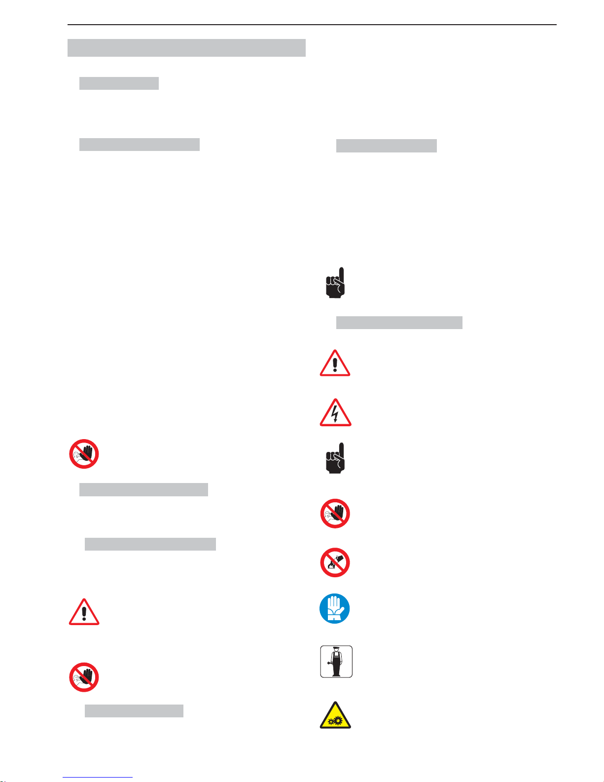
1.3.4. Símbolos utilizados
PELIGRO GENÉRICO
Indica un peligro que conlleva riesgo incluso mortal para el usuario.
En este caso se debe proceder prestando máxima atención y respetando todas las instrucciones en cuanto a seguridad de intervención.
PELIGRO DE SUFRIR CHOQUE ELÉCTRICO
Indica al personal respectivo que, si no es ejecutada respetando la
normativa de seguridad, la operación descrita conlleva riesgo de
sufrir choque eléctrico.
ADVERTENCIA
Se refi ere a una advertencia o nota sobre funciones esenciales o
informaciones útiles.
Se debe prestar máxima atención a los bloques de texto indicados
mediante este símbolo.
PROHIBICIÓN
La presencia de esta señal indica las operaciones cuya ejecución
debe evitarse absolutamente ya que conllevan peligro para el usuario
y demás personas que operan en las proximidades de la máquina.
PROHIBICIÓN DE APAGAR LOS INCENDIOS CON AGUA
La presencia de esta señal indica la prohibición de apagar los incendios con agua o con cualquier sustancia que la contenga.
PROTECCIÓN PERSONAL
La presencia del símbolo expuesto al costado de la descripción
comporta para el operador la obligación de uso de dispositivos de
protección personal, ya que existe riesgo implícito de accidente.
TÉCNICO ESPECIALIZADO
Identifi ca las intervenciones que pueden ser ejecutadas sólo por
personal técnico especializado.
ÓRGANOS EN MOVIMIENTO
Identifi ca el peligro por los órganos en movimiento presentes sobre
la máquina. Apagar la máquina antes de efectuar cualquier operación.
Page 34
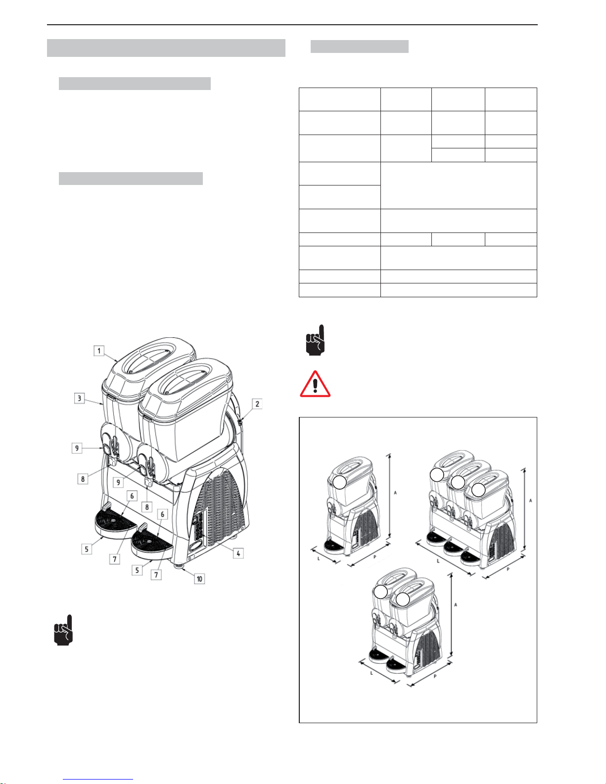
- 4 _ES- SL310005700 Ed.00 - 04-2011
2. DESCRIPCIÓN DE LA MÁQUINA
2.1. Uso previsto de la máquina
La máquina de uso profesional que estáis utilizando, es idónea para la producción de granizados y bebidas frías. En el caso de que se utilice con productos
a base de leche y/o cuando las leyes lo prevean según los productos utilizados,
tiene que contar con la opción “visualizador de temperatura” del producto en el
depósito. Además, hay que respetar imperativamente las normas vigentes para
los productos utilizados.
2.2. Principales componentes
Los principales componentes de la máquina son:
1 Tapa depósito
2 Regulador de densidad
3 Depósito
4 Panel de mandos
5 Bandeja receptora de goteo
6 Rejilla de goteo
7 Flotador cubeta llena
8 Grifo dispensador
9 Leva del grifo
10 Pies
Fig.1
2.3. Datos técnicos
A continuación se indican los datos y las características técnicas.
Modelo
Granitore 1
Granitore 1 FF
Granitore 2
Granitore 2 FF
Granitore 3
Granitore 3 FF
Dimensiones
L x P x H (mm).
27 x 52 x 81 47 x 52 x 81 67 x 52 x 81
Peso (kg)
(depósito vacío)
29
47 68
52 70
Potencia máxima consumida (W)
Véase placa de datos técnicos situada en el
costado de la máquina
Tensión de funcionamiento (V)
Temperatura de funcionamiento
Min. 20°C
Max. 32°C
Número de depósitos 1 2 3
Capacidad de cada de-
pósito agua (l)
12
Presión sonora << 70 dB
A
Clase N
Fig.2
A fi n de facilitar la lectura de las instrucciones, en la presente
publicación se utilizan las siguientes abreviaciones:
Granitore 1, identifi ca la Granizadora de (1) un depósito;
Granitore 2, identifi ca la Granizadora de (2) dos depósitos;
Granitore 3, identifi ca la Granizadora de(3) tres depósitos;
Granitore 1 FF, identifi ca la Granizadora de (1) dos depósitos con instalación
frigorífi ca Fast Freeze;
Granitore 2 FF, identifi ca la Granizadora de (2) dos depósitos con instalación
frigorífi ca Fast Freeze;
Granitore 3 FF, identifi ca la Granizadora de (3) tres depósitos con instalación
frigorífi ca Fast Freeze.
Nota. El fabricante se reserva el derecho de efectuar modifi ca-
ciones a la máquina sin obligación de aviso previo.
¡Atención! Cualquier modifi cación y/o instalación de acceso-
rios adicionales deberá ser explícitamente aprobada y realizada
por el fabricante.
1
1 2
1
3
2
Page 35
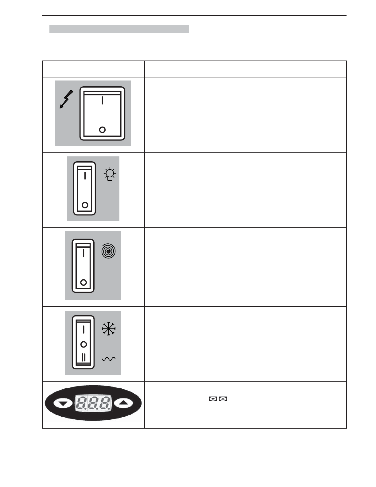
SL310005700 Ed.00 - 04-2011 - 5 _ES-
2.4. Descripción funciones del panel de mandos
Los mandos de la máquina se encuentran en el respectivo panel situado en su parte lateral.
MANDO MODELO FUNCION
TODOS
Interruptor General: tiene la función de mandar:
- el encendido de la máquina;
- el apagado de todas las funciones presentes en la máquina.
TODOS
Interruptor iluminación tapa: para encender/apagar la iluminación (si presen-
te) sobre las tapas de los depósitos.
TODOS
Interruptor mezcla depósito (uno por depósito): tiene la función de gober-
nar el encendido y el apagado del motorreductor que acciona el mezclador
del producto del depósito correspondiente.
TODOS
Desviador instalación frigorífica (uno por depósito):
- en posición “0”, la instalación frigorífi ca es desactivada;
- en posición “I”, la instalación frigorífi ca es activada para la producción de
granizados;
- en posición “II”, la instalación frigorífi ca es activada para la producción de
bebidas frías.
TODAS LAS VERSIO-
NES CON TERMOSTA-
TO ELECTRÓNICO
Termostato electrónico:
- Muestra la temperatura del producto en el depósito y mediante las teclas
se puede variar la temperatura de la bebida cuando la máqui-
na trabaja en modo “bebida fría”.
Page 36
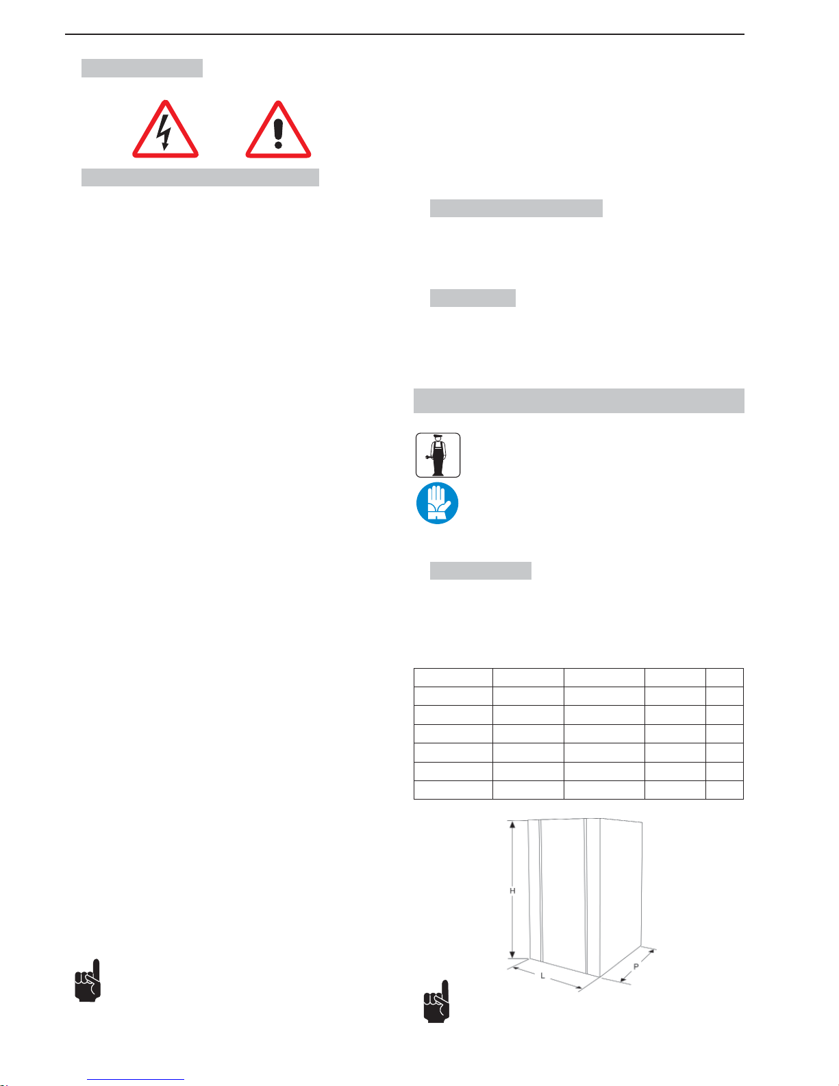
- 6 _ES- SL310005700 Ed.00 - 04-2011
3. SEGURIDAD
3.1. Normas generales de seguridad
• Léase atenta y enteramente el manual de instrucciones.
• El enlace a la red eléctrica debe efectuarse según lo establecido por las
normas de seguridad vigentes en el país de uso.
• La toma de corriente a la cual conectar la máquina debe:
- corresponder al tipo de enchufe instalado en la misma;
- ser dimensionada respetando las indicaciones de la placa de datos presente en el costado de la máquina;
- ser conectada a un sistema efi ciente de contacto de tierra;
- conectada a un sistema con diferencial y magnetotérmico.
• El cable de alimentación no debe:
- entrar en contacto con ningún tipo de líquido: peligro de choque eléctrico
y/o de incendio;
- ser aplastado ni entrar en contacto con superfi cies cortantes;
- ser utilizado para desplazar la máquina;
- ser utilizado cuando está dañado;
- ser manipulado con las manos húmedas o mojadas;
- ser enrollado en madeja durante el funcionamiento de la máquina;
- ser alterado.
• Queda prohibido:
- instalar la máquina con modalidades diferentes de aquéllas ilustradas en
el Cap. 5;
- instalar la máquina en zonas en las que sea posible utilizar un chorro de
agua;
- utilizar la máquina en proximidad de sustancias infl amables y/o explosivas;
- dejar al alcance de los niños bolsas de plástico, poliestirol, clavos, etc.,
ya que son potenciales fuentes de peligro;
- dejar que los niños jueguen y permanezcan en proximidad de la máquina.
- utilizar recambios no aconsejados por la empresa fabricante;
- introducir cualquier modifi cación técnica en la máquina;
- sumergir la máquina en cualquier tipo de líquido;
- lavar la máquina con chorros de agua;
- utilizar la máquina con modalidades diferentes de aquéllas indicadas en
el manual;
- utilizar la máquina en condiciones psicofísicas alteradas por infl uencia de
drogas, alcohol, psicofármacos, etc.;
- instalar la máquina sobre otros aparatos;
- el uso de la máquina en ambientes potencialmente explosivos, agresivos
o con alta concentración de polvos o sustancias aceitosas en suspensión
en el aire;
- el uso de la máquina en ambientes sujetos a riesgo de incendio;
- el uso de la máquina para suministrar sustancias no previstas considerando las características de la misma.
• Antes de limpiar la máquina controlar que el enchufe esté desconectado
de la toma de corriente. No lavar la máquina con bencina ni solventes de
ninguna naturaleza.
• Toda reparación puede ser ejecutada sólo por un Centro de Asistencia Autorizado por el Fabricante y/o, en todo caso, por personal especializado y
capacitado.
• No obstruir las rejillas situadas en los costados de la máquina.
• No colocar la máquina en proximidad de sistemas de calefacción (tales
como estufas o radiadores).
• En caso de incendio utilizar extintores de anhídrido carbónico (CO
2
). No
utilizar agua ni extintores de polvo.
Todo uso impropio provocará la invalidación total de la garantía,
declinando el fabricante toda responsabilidad por posibles lesiones a las personas y/o daños a las cosas que de ello deriven.
Es de considerar como uso impropio:
- cualquier uso diferente del previsto y/o con aplicación de técnicas diferentes
de aquéllas ilustradas en esta publicación;
- cualquier intervención que se efectúe en la máquina en contraste con las
indicaciones expuestas en esta publicación;
- todo uso después de alteraciones de componentes y/o de dispositivos de
seguridad;
- todo uso después de reparaciones efectuadas con uso de componentes no
autorizados por el fabricante;
- la instalación de la máquina al aire libre.
3.2. Funciones de parada
Las funciones de parada de la máquina se obtienen mediante el interruptor
general.
3.3. Placas
NINGUNA DE LAS PLACAS PRESENTES EN LA MÁQUINA DEBE SER
RETIRADA, CUBIERTA O DAÑADA, ESPECIALMENTE AQUÉLLAS QUE
SE REFIEREN A LA SEGURIDAD.
4. DESPLAZAMIENTO Y ALMACENAMIENTO
Todas las operaciones ilustradas en el capítulo 4 son de exclusiva competencia de los técnicos especializados en elevación
y desplazamiento de máquinas embaladas y desembaladas.
En función de las características y del peso del aparato a
desplazar, dichos técnicos deberán organizar las diferentes
secuencias operativas y el empleo de medios adecuados de
elevación y transporte, operando en todo momento con rigu-
rosa aplicación de las normas vigentes en esta materia.
4.1. Embalaje
La máquina se envía lista para el uso, embalada en una caja de cartón. La caja
de cartón está compuesta por una base y una cubierta, fi jadas mediante dos
cintas de nylon.
DIMENSIONES Y PESO DE LA MÁQUINA EMBALADA
Anchura (L) Profundidad (P) Altura (H) Peso
Granitore 1 340 mm 540 mm 930 mm 32 kg
Granitore 1 FF 340 mm 540 mm 930 mm 32 kg
Granitore 2 560 mm 540 mm 930 mm 52 kg
Granitore 2 FF 560 mm 540 mm 930 mm 57 kg
Granitore 3 770 mm 540 mm 930 mm 72 kg
Granitore 3 FF 770 mm 540 mm 930 mm 74 kg
Nota. Las dimensiones y el peso de la máquina embalada se
indican de manera aproximada.
Fig.3
Page 37
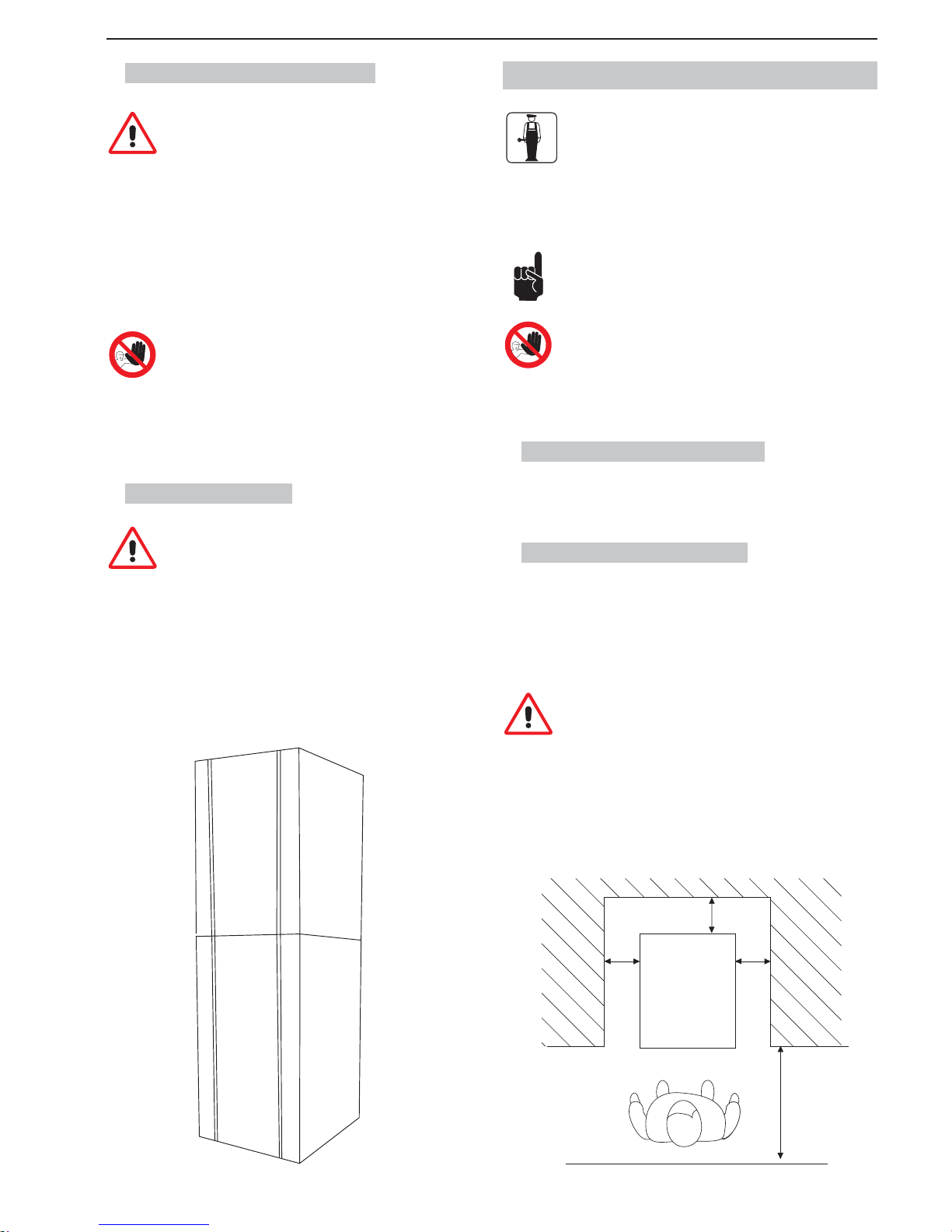
SL310005700 Ed.00 - 04-2011 - 7 _ES-
4.2. Transporte y desplazamiento
Controlar que ninguna persona esté presente dentro del radio
operativo de elevación y desplazamiento de la carga y, en situaciones de particular difi cultad, utilizar personal que controle los
desplazamientos a efectuar.
El desplazamiento manual de la máquina debe ser efectuado al menos por
dos personas.
La máquina debe ser desplazada en posición vertical y sólo después de
haber vaciado todos los depósitos de los productos que contienen.
Elevar la máquina embalada y transportarla procediendo con cautela; evítense
trayectos accidentados, prestando atención a las dimensiones y posibles piezas sobresalientes.
Atención. Está prohibido practicar cortes adicionales en el
embalaje.
Los daños que la máquina pueda sufrir durante su transporte y desplazamiento no están cubiertos por la GARANTÍA.
Reparaciones o sustituciones de piezas eventualmente dañadas deben
efectuarse por cuenta y a cargo del cliente.
4.3. Almacenamiento
Antes de almacenar la máquina o al reactivarla después de un
período de almacenamiento, será indispensable efectuar una
cuidadosa limpieza e higienización de la máquina misma.
Atención. Al efectuar el almacenamiento no sobreponer más de dos máquinas.
En caso de prolongada inactividad, la máquina debe ser almacenada adoptando las precauciones que correspondan considerando el lugar y el período
previsto de almacenamiento, esto es:
• almacenar la máquina en lugar cerrado;
• proteger la máquina contra golpes y presiones;
• proteger la máquina contra humedad y oscilaciones térmicas elevadas;
• evitar que la máquina entre en contacto con sustancias corrosivas.
MAX
MAX
Fig.4
5. INSTALACIÓN
Todas las operaciones ilustradas en el capítulo 5 son de exclusiva competencia de técnicos especializados, los que deberán
organizar las diferentes secuencias operativas y el empleo de
medios adecuados para actuar en todo momento con rigurosa
aplicación de las normas vigentes en esta materia.
La máquina debe ser instalada en el interior de un edifi cio iluminado, aireado y
provisto de pavimento sólido, nivelado (inclinación inferior a 2º) y estable.
La máquina es del tipo con vigilancia, por lo que deberá ser
instalada en un lugar en que pueda ser observada por personal
capacitado.
Atención: está prohibido instalar la máquina en sitios donde
pueda ser alcanzada, tocada y/o accionada por personas diferentes de las especifi cadas en el apartado 1.2.
La máquina debe funcionar en ambientes con temperatura comprendida entre
20 °C y 32 °C
5.1. Lista de accesorios de serie
• Vaselina: para lubricar todas las piezas indicadas en el presente manual
después de efectuar las operaciones de lavado e higienización.
5.2. Montaje y emplazamiento
El operador debe efectuar las siguientes verifi caciones:
• que el local haya sido preparado para instalar la máquina;
• que la superfi cie de emplazamiento sea sólida, plana y estable;
• que el local reúna los requisitos previstos en cuanto a iluminación, aireación
e higiene y que la toma de corriente sea de fácil acceso.
Deben dejarse libres espacios adecuados de acceso a la máquina a fi n de que el operador pueda intervenir en ella sin difi culta-
des y pueda también abandonar rápidamente el área de trabajo
en caso de necesidad.
En fi gura 5 se indican las distancias mínimas necesarias para efectuar la ins-
talación.
150 cm
60 inches
25 cm
10 inches
25 cm
10 inches
25 cm
10 inches
Fig.5
Page 38
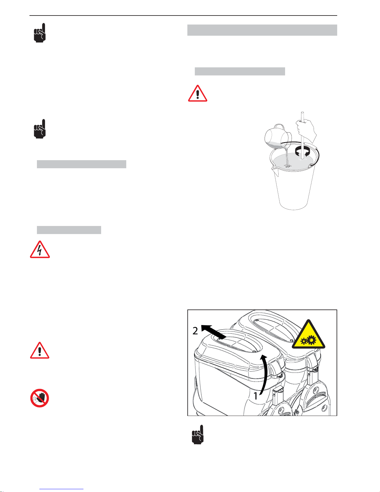
- 8 _ES- SL310005700 Ed.00 - 04-2011
AGUA
Nota: Dejar un espacio de 25 cm (10 pulgadas) en el lado superior.
En la fi g. 5 se indican los espacios requeridos para los accesos:
• a la botonera situada en la parte lateral derecha;
• a las unidades que puedan requerir intervención en caso de malfuncionamiento de la máquina.
Una vez situada la máquina embalada en proximidad de la zona de emplazamiento, se deberá proceder de la siguiente forma:
1. cortar las cintas de nylon que mantienen cerrado el embalaje;
2. elevar la cubierta de cartón;
3. a continuación emplazar la máquina en el lugar previsto para ello.
Antes de poner en funcionamiento la máquina por primera vez se
deberá efectuar una cuidadosa limpieza de los componentes de
la misma además de la higienización de las piezas que entran en
contacto con el producto; para mayores detalles sírvase consultar
el respectivo apartado.
5.3. Tratamiento del embalaje
Una vez abierto el embalaje, se recomienda subdividir según su tipo los materiales que lo componen y tratarlos según lo dispuesto por las normas vigentes
en el país de destino.
Aconsejamos conservar el embalaje ya que podría ser útil para efectuar sucesivos desplazamientos o transportes de la máquina.
5.4. Enlace eléctrico
Esta operación debe ser ejecutada sólo por personal técnico
especializado.
Antes de introducir el enchufe en la toma de corriente se deberá controlar que
el interruptor general se encuentre en posición “0”.
El enlace eléctrico de la máquina deberá ser realizado a cargo y bajo la responsabilidad del cliente.
La máquina debe ser conectada a la línea eléctrica mediante el enchufe ya
presente en el cable eléctrico, considerando:
• las leyes y normas técnicas vigentes en el momento de efectuarse la instalación;
• los datos indicados en la placa de datos técnicos que está fi jada en el costado
de la máquina.
Atención. El punto de conexión de la toma de corriente debe ser
de fácil acceso para el usuario, a fi n de que pueda desconectar
sin difi cultades la máquina respecto de la línea eléctrica cada
vez que ello sea necesario.
En caso de dañarse el cable de alimentación, para su sustitución se deberá contactar exclusivamente al fabricante o a un técnico especializado.
Queda prohibido:
• el uso de alargadores de cualquier tipo;
• sustituir el enchufe original;
• el uso de adaptadores.
6. FUNCIONAMIENTO
Antes de efectuar la primera puesta en funcionamiento el técnico especializado deberá verifi car que la máquina esté correctamente instalada.
6.1 Preparación del producto
Atención. El producto puede ser vertido en el depósito sólo
con máquina detenida y enchufe desconectado de la toma de
corriente.
Fig.6
Diluir y mezclar en un recipiente el CONCENTRADO con AGUA según las indicaciones del productor. LA MEZCLA OBTENIDA DEBE TENER UN CONTENIDO MÍNIMO DE 13° BRIX DE AZÚCAR. Atención, ya que una concentración
menor puede dañar las palas espirales y/o los motorreductores.
NO USAR NUNCA SÓLO AGUA
Para quitar la tapa del depósito seguir los pasos siguientes:
1 levantar la tapa en la parte trasera;
2 sacar la tapa del retén que hay en la parte delantera.
Atención: si cuesta abrir la tapa no forzar su apertura.
Fig.7
Page 39
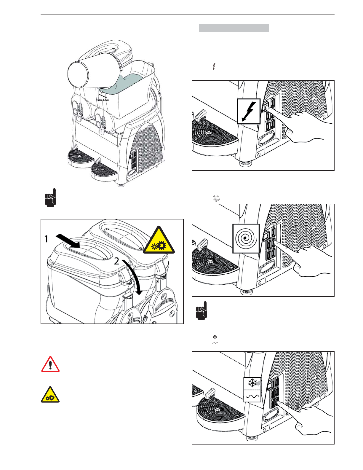
SL310005700 Ed.00 - 04-2011 - 9 _ES-
Verter el producto en el depósito prestando atención a fi n de no
superar el nivel máximo indicado.
NO INTRODUCIR LÍQUIDOS CALIENTES
(con temperaturas superiores a 25 °C)
Fig.8
Fig.9
Después de haber vertido el producto en el depósito, cerrar esta última con la
tapa.
Atención. No poner en funcionamiento la máquina sin que la
tapa esté cerrada. Antes de quitar la tapa, apagar la máquina y
desconectar el enchufe respecto de la toma de corriente.
Atención: dentro del depósito se encuentran órganos en movimiento que pueden causar lesiones; apagar la máquina y desconectar el enchufe respecto de la toma de corriente antes de
intervenir dentro del depósito.
6.2. Arranque Granitore
Para simplifi car la explicación, se ilustrará sólo el accionamiento del depósito
derecho; para accionar los restantes basta ejecutar la misma secuencia de
operaciones en los interruptores de cada uno de ellos.
Interruptor
en posición “I”: máquina en tensión.
Fig.10
Cada depósito es mandado por un interruptor y un desviador que deben ser
accionados de la manera siguiente:
Interruptor en posición “I”: mezclador en funcionamiento.
Fig.11
Si el aparato lleva un temporizador consulte el apartado 6.7
para programarlo correctamente.
Para obtener un GRANIZADO:
Desviador : en pos. “I” sistema de refrigeración en función (hielo).
Fig.12
Page 40
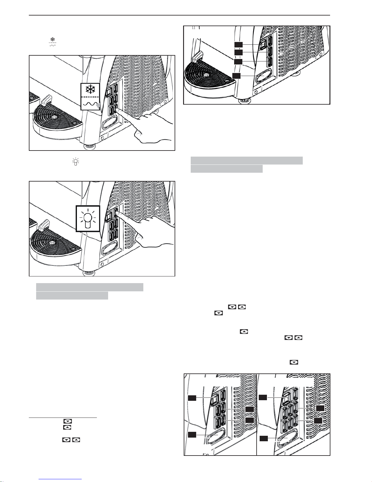
- 10 _ES- SL310005700 Ed.00 - 04-2011
Para obtener una BEBIDA FRÍA:
Desviador : en pos. “II” sistema de refrigeración en función (bebida).
Presionar el interruptor
de iluminación tapa para encender la tapa luminosa
presente en la máquina.
Fig.13
Fig.14
6.3. Puesta en marcha Granizadora 1
(Termostato electrónico)
El visualizador de temperatura tiene la función de mostrar la temperatura del
producto en el depósito y regularla cuando la máquina esté en función “refrigeración bebida”.
Interruptor (A) en posición “I“: Máquina bajo tensión.
Interruptor (C) en posición “I“: Mezclador en funcionamiento
Para obtener un GRANIZADO:
Interruptor (D) en posición “I“: Instalación refrigeración en marcha (granizado).
Para obtener una BEBIDA FRÍA:
Interruptor (D) en posición “II“: Instalación refrigeración en marcha (bebida).
Para inhabilitar la REFRIGERACIÓN (solo agitación):
Desviador (D) en posición “0“: Instalación refrigeración inhabilitada (sólo agitación).
Ajuste del set-point de temperatura
- Apretar la tecla . La pantalla electrónica muestra PrG.
- Apretar la tecla . La pantalla electrónica muestra el valor del set-point de
temperatura.
-
Con las teclas se puede variar el valor de set-point desde 0°C ÷
10° C.
Después de 3 segundos desde la presión de la última tecla el dato es memorizado y la pantalla electrónica muestra la temperatura del producto en el
depósito.
ALARMAS
En caso de sonda averiada la pantalla electrónica muestra el letrero A1.
La salida de regulación y la programación están inhabilitadas.
6.4. Puesta en marcha Granizadora 2/3
(Termostato electrónico)
Por sencillez se mostrará cómo accionar solamente el depósito derecho; para
accionar los restantes sólo tenemos que cumplir la misma secuencia de operaciones con los interruptores del depósito que nos interese.
Interruptor (A) en posición “I“: Máquina en tensión.
Interruptor (C) en posición “I“: Mezcladores en marcha.
Para obtener un GRANIZADO:
Desviadores (D) en posición “I“: Instalación refrigeración en marcha (granizado).
Para obtener una BEBIDA FRÍA:
Desviadores (D) en posición “II“: Instalación refrigeración en marcha (bebida).
Para inhabilitar el REFRIGERADOR (solo agitación):
Desviadores (D) en posición “0“: Instalación refrigeración inhabilitada (sólo
agitación).
Establecer el set-point de temperatura
- Con el termostato electrónico habilitado (encendido), apretar contemporáneamente las teclas la pantalla electrónica muestra “t1”.
- Con la tecla se pueden recorrer los set-point “t1”; “t2” (Máquinas 2
depósitos), “t1”; “t2”; “t3” (Máquina 3 depósitos).
- uando la pantalla electrónica muestra el set-point que se quiere variar (“t1”o
“t2” o “t3”), apretar la tecla para visualizar el valor del set-point.
- Es por lo tanto posible modifi car mediante las teclas el valor de set-
point desde 0°C ÷ 10°C.
• espués de tres segundos a partir de la presión de la última tecla el dato se
memoriza. La pantalla electrónica vuelve a mostrar “t1”o “t2” o “t3” según
el set-point que se haya modifi cado. Apretar la tecla hasta cuando la
pantalla electrónica muestre la temperatura del producto en el depósito.
2 CUBAS
3 CUBAS
A
E
D
C
E
A
C
D
Fig.16
A
C
D
E
Fig.15
Page 41
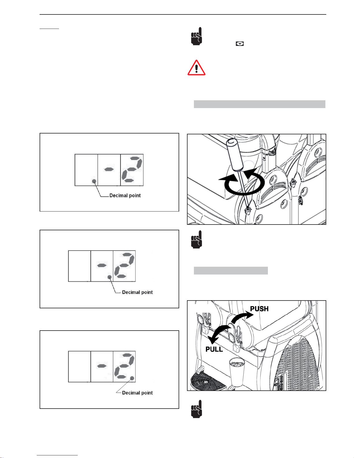
SL310005700 Ed.00 - 04-2011 - 11 _ES-
6.5. Regulación de la consistencia del granizado
Es posible modifi car la consistencia del granizado (+/-) regulando la misma
mediante el tornillo ilustrado en el dibujo de la siguiente forma: +: mayor con-
sistencia, -: menor consistencia.
6.6. Suministro granizado
Para tomar la bebida actuar sobre la palanca del grifo.
La regulación puede ser realizada manualmente o utilizando un
destornillador plano idóneo.
Fig.20
Fig.21
ALARMAS
En caso de sonda averiada la pantalla electrónica muestra los siguientes mensajes de alarma:
“A1”: Sonda depósito 1 desconectada
“A2”: Sonda depósito 1 en corto circuito
“A3”: Sonda depósito 2 desconectada
“A4”: Sonda depósito 2 en corto circuito
“A5”: Sonda depósito 3 desconectada
“A6”: Sonda depósito 3 en corto circuito
Durante el funcionamiento, el termostato electrónico muestra la temperatura
del producto en los depósitos mostrando cíclicamente cada 3 segundos la temperatura del producto de un cada depósito.
Para entender a qué depósito se refi ere la temperatura mostrada por el termos-
tato electrónico hay que tomar referencia a cual decimal point está visualizado.
Si el decimal point visualizado está a la izquierda, la temperatura indicada se
refi ere al depósito 1 (Ver Fig.2 Página 4).
Si el decimal point visualizado es central, la temperatura indicada se refi ere al
depósito 2 (Ver Fig.2 Página 4).
Si el decimal point visualizado es a la derecha, la temperatura indicada se
refi ere al depósito 3 (Ver Fig.2 Página 4).
Fig.18
2 CUBAS
Fig.19
3 CUBAS
Fig.17
Nota: Si durante el empleo de la máquina inadvertidamente se
tuviera que apagar el termostato electrónico, para reactivarlo
apretar la tecla . Si el termostato electrónico ya no se reac-
tivara, apagar la máquina y dirigirse al centro de asistencia.
Atención: Durante el empleo de la máquina, el termostato electrónico tiene que estar siempre activo para poder visualizar
siempre la temperatura del producto en los depósitos.
Controlar periódicamente la temperatura del producto en el depósito con un termómetro a gas para verifi car que el producto
esté siempre por debajo de la temperatura de conservación. Para
modelos de máquina equipada con visualizador de temperatura
o termostato electrónico, verifi car también que la temperatura
del producto, detectada con termómetro a gas, corresponda a
Page 42
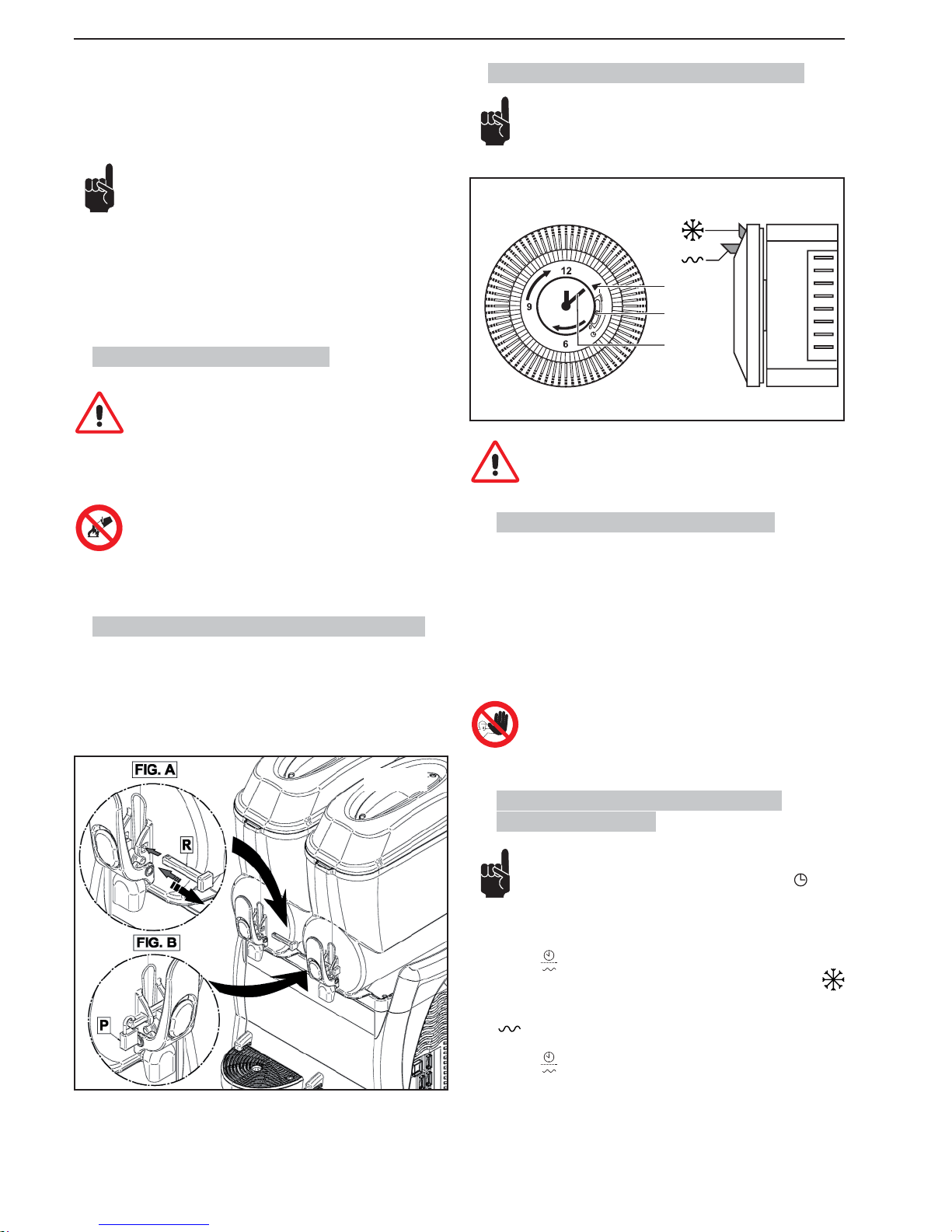
- 12 _ES- SL310005700 Ed.00 - 04-2011
Fig.22
6.9. Accesorios opcionales (Temporizador)
El temporizador mostrado es solo un ejemplo.
A
B
C
Fig.23
Las programaciones del temporizador tienen que hacerse con
el interruptor general en la posición -0- y con la clavija quitada
de la toma de corriente.
6.9.1. Programación de la hora actual
Antes de empezar a utilizar el temporizador hay que ajustar el día y la ahora
actuales.
Para ajustarlos hay que girar el cuadrante del temporizador en el sentido que
indica la fl echa hasta que el indicador (A) no indique el día exacto y después
seguir girando la aguja (C) hasta poner la hora actual.
Está prohibido:
• girar la aguja con cualquier instrumento;
• girar la aguja en el sentido contrario del que muestra el
temporizador.
6.9.2. Funcionamiento del aparato con
temporizador
En todos los aparatos que llevan temporizador hay que comprobar que el selector (B) esté en la posición central
.
El aparato tiene que ponerse en marcha como muestra el apartado 6.2.
Conmutador
en posición “I”:
- para el granizado ponga la lengüeta del temporizador en la posición
en el día y la hora deseados;
- para la bebida fría ponga la lengüeta del temporizador en la posición
en el día y la hora deseados.
Conmutador
en posición “II”:
el aparato anula el temporizador y funciona solamente como bebida fría.
la temperatura visualizada por la máquina. Con el producto en
el depósito todavía por consumir, no quitar nunca la corriente
a la máquina y no apagar nunca el interruptor general, dejando
la máquina encendida en la función granizado o bebidas frías.
Si la máquina no se utiliza con continuidad, en caso de
productos a base de leche, hay que:
- Rociar la solución sanadora en la zona del grifo y en el
mismo grifo (como alternativa de lavar con un paño limpio y saneador);
o bien:
- Tomar una pequeña cantidad de producto del grifo antes
de dispensar la dosis para el cliente.
6.7. Situaciones de emergencia
ATENCIÓN. En caso de emergencia, para detener la máquina se
debe presionar con energía el interruptor general disponiéndolo en posición -0-.
En caso de congelación, apagar la máquina y contactarse con el centro de
asistencia o con un técnico especializado.
En caso de incendio se debe abandonar inmediatamente la zona
para permitir la intervención de personal capacitado y equipado con
medios de protección adecuados. Utilizar siempre extintores homologados. No emplear nunca agua ni otras sustancias no fi ables.
6.8. Accesorio (Opcional) (Sistema De Cierre)
Utilizar el nuevo sistema de bloqueo del grifo de la manera siguiente:
Fig. A: Durante el uso de la máquina, poner el soporte “R” como indicado
en la fi gura.
Fig. B: Para bloquear la empuñadura, poner el soporte “R” en su agujero
y el candado como indicado en la fi gura.
Page 43
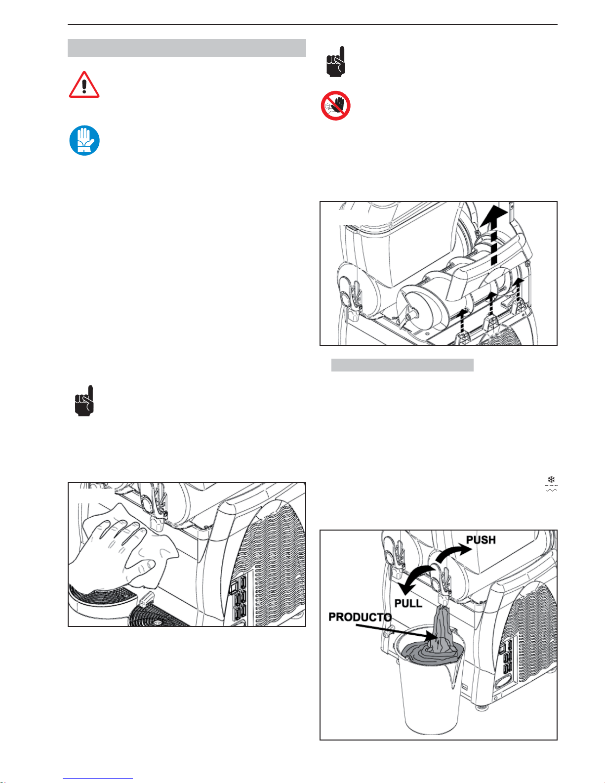
SL310005700 Ed.00 - 04-2011 - 13 _ES-
7. LIMPIEZA Y MANTENIMIENTO
La limpieza y el mantenimiento de los componentes externos
de la máquina debe efectuarse disponiendo previamente el interruptor general en posición -0- y desconectando el enchufe
respecto de la toma de corriente.
Antes de efectuar cualquier operación relativa a la limpieza y
mantenimento de la máquina, ponerse las protecciones personales (guantes, gafas, etc..) fi jadas por las normativas de segu-
ridad en vigor en el país donde se emplea la máquina.
Al efectuar los trabajos de Limpieza o Mantenimiento, aplicar lo que se describe a continuación:
• ponerse guantes de protección para la prevención de accidentes;
• no utilizar solventes ni materiales infl amables;
• prestar atención a fi n de no dispersar líquidos en el ambiente;
• no utilizar esponjas abrasivas y/o metálicas para limpiar la máquina y sus
componentes;
• no lavar los componentes de la máquina en lavavajillas;
• no utilizar un horno convencional ni microondas para secar piezas de la
máquina;
• no sumergir la máquina en agua;
• no aplicar a la máquina chorros de agua de modo directo;
• lavar utilizando exclusivamente agua tibia y un higienizante adecuado (conforme con lo dispuesto por las normativas vigentes en el país de uso) que
no provoque daños en los componentes de la máquina;
• al concluir estas tareas reinstalar y fi jar correctamente todas las proteccio-
nes y cubiertas que han sido retiradas o abiertas.
La limpieza y la higienización son operaciones que deben efectuarse habitualmente con cuidado máximo a fi n de garantizar la calidad de la producción y
aplicar las necesarias normas higiénicas.
La limpieza e higienización del depósito se tiene que efectuar
al menos una vez al día y en cualquier caso respetando las nor-
mas higiénicas vigentes en el país de empleo. Estas operaciones se tienen que realizar más a menudo en el caso en que las características del producto utilizado lo requieran; para más detalles consultar al
suministrador del producto. En el caso en que la máquina no se use con
una cierta continuidad durante el día, lavar con un paño limpio y solución
higienizante la zona del grifo y el conducto de salida del producto, como
se indica en la fi gura de abajo.
Fig.24
El uso de materiales inoxidables, plásticos y de gomas para la
fabricación de dichos componentes, así como su forma particular, facilitan la ejecución de la limpieza pero no impiden la formación de bacterias y moho en caso de limpieza insufi ciente.
Está prohibido limpiar o efectuar mantenimiento de la máquina
con el interruptor general en posición -1- y con el enchufe conectado en la toma de corriente.
Si fuera necesario, para realizar el mantenimiento y la limpieza de la máquina
se pueden desmontar las partes de arriba. Cuando se han concluido las operaciones volver a montar la parte en el panel lateral.
7.1. Vaciado de los depósitos
Antes de limpiar cada depósito es necesario retirar de ellas el producto preparado anteriormente.
Para efectuar la limpieza precedente al primer uso no es necesario vaciar
el depósito; consúltese al respecto el apartado 7.2.
Para simplifi car la explicación, se ilustrará sólo el vaciado del depósito derecho;
para vaciar los restantes depósitos basta ejecutar la misma secuencia de operaciones en los mandos de cada una de ellas.
El procedimiento descrito a continuación es válido ya sea para los modelos con
y sin termostato electrónico.
Con la máquina encendida, disponer el desviador de la unidad frigorífi ca
en “0” y vaciar el tanque.
Fig.26
Fig.25
Page 44
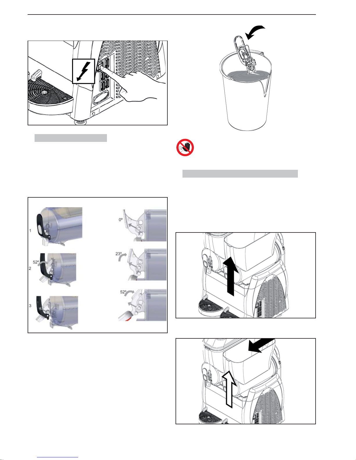
- 14 _ES- SL310005700 Ed.00 - 04-2011
Está prohibido desmontar el grifo con presencia de producto o
de cualquier otro líquido en el depósito.
7.3. Desmontaje del depósito y de la tapa
El desmontaje de cada depósito presente en la máquina es fundamental para
poder efectuar una correcta limpieza e higienización de la máquina.
Para desmontar correctamente un depósito se debe proceder de la siguiente
forma:
1 Desmontar la tapa como indicado al párrafo 6.1.
2 desmontar el depósito elevando su parte delantera hasta desengancharla;
Por último, disponer en Off el interruptor mezclador y el interruptor general ;
desconectar el enchufe respecto de la toma de corriente.
7.2. Desmontaje del grifo
Antes de desmontar el depósito es conveniente desmontar el grifo; no obstante, la posterior instalación del grifo se llevará a cabo una vez que el depósito
haya sido correctamente reinstalado.
Desmontar el grifo: sacando los pernos de sus alojamientos. Para ello presionar la pieza push del grifo hasta hacer tope con el depósito como se indica en
la fi gura y estirar del grifo hacia arriba hasta desencajar los pernos.
Los componentes pueden ser depositados en una cubeta con agua caliente
(aprox. 50 °C); asimismo, para llevar a cabo una limpieza cuidadosa proceder
de la manera ilustrada en el apartado .7.4.
Fig.28
Fig.29
Fig.30
3 empujando la parte trasera (aplicar pequeños golpes) hacer salir el depósito
de su alojamiento;
Fig.31
4 extraer la pala espiral y quitar las juntas (A) y (B).
Fig.27
Page 45
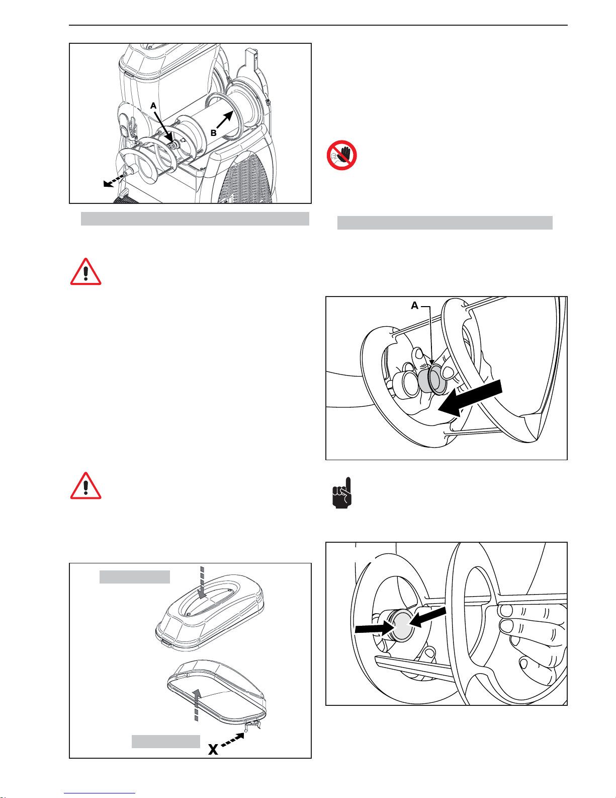
SL310005700 Ed.00 - 04-2011 - 15 _ES-
Fig.32
7.4. Lavado e higienización de los componentes
Todos los componentes precedentemente desmontados deben ser cuidadosamente lavados e higienizados.
Atención. La solución higienizante debe reunir las caracterís-
ticas establecidas por las normas vigentes en el momento del
uso de la máquina.
Para realizar correctamente este procedimiento, se deberán realizar las siguientes operaciones:
1 llenar un recipiente con una solución higienizante preparada en agua (2% de
hipoclorito de sodio en solución con agua)
2 lavar bien el depósito, la tapa y el evaporador con una esponja humedecida
con solución higienizante
3 enjuagar bien con agua limpia
4 llenar otro recipiente con la solución higienizante
5 sumergir los componentes desmontados en la solución higienizante
6 dejar en remojo durante 30 minutos los componentes desmontados en la
solución higienizante
7 enjuagar bien con agua limpia
8 colocar los componentes sobre una superfi cie limpia y secarlos
9 volver a montar la máquina como se describe en el apartado 7.5
10 antes de volver a utilizar la máquina hacer un ciclo de enjuague con agua
limpia (véase el apartado 7.6)
Atención. No sumergir en ningún líquido las tapas provistas de
iluminación. Antes de efectuar las operaciones de limpieza y de
higienización de la tapa, hay que desmontarlo de la máquina
como describido en el capítulo precedente.
Para limpiar correctamente la tapa luminosa siga los pasos siguientes;
1. limpie primero con un trapo limpio y húmedo la parte inferior de la tapa (en
contacto con el producto)
2. limpie con un trapo limpio y húmedo toda la parte exterior
Fig.33
Parte exterior
Parte inferior
Fig.35
Fig.34
7.5. Ensamblaje de los componentes lavados
Los componentes lavados e higienizados deben ser reensamblados con gran
atención. Algunos componentes deben ser adecuadamente lubricados para
garantizar su correcto funcionamiento.
Instalar la junta (A) en la pala espiral procediendo de la manera ilustrada en
la fi g.34.
Nota importante: controlar siempre la integridad de la junta y sustituirla con otra nueva si se encuentra deteriorada. La junta (A) debe
ser sustituida por lo menos una vez por año.
Lubricar la junta (A) en las zonas indicadas en la fi g.35, utilizando la vaselina
suministrada adjunta.
3. con una esponja humedecida con desinfectante desinfecte la parte inferior
de la tapa; cuidado con no mojar los contactos (X)
4. deje actuar durante 30 minutos
5. enjuagar dos veces o más, sólo la parte inferior, con una esponja limpia
humedecida con agua fresca.
6. poner la tapa en una superfi cie limpia y secarla; secar primero la parte de
abajo y luego la de fuera con un paño limpio.
7. vuelva a poner la tapa solo después de haber limpiado y desinfectado el
depósito.
Está prohibido lavar y/o higienizar la tapa cuando está montada
en la máquina.
Page 46
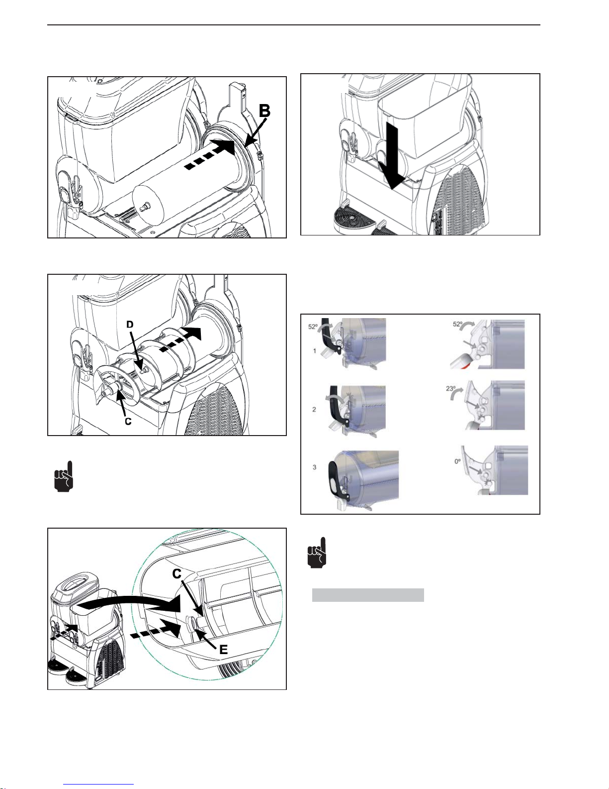
- 16 _ES- SL310005700 Ed.00 - 04-2011
Fig.36
Fig.37
Instalar la junta (B) lubricándola con vaselina en toda la superfi cie indicada
mediante las fl echas.
Introducir la pala espiral haciendo enganchar el cabezal (C) en el eje (D).
Fig.38
Nota: La pala espiral se encaja rodándola alrededor del evaporador.
Posicionar el depósito en su alojamiento; levantar un poco la cabeza (C) de la
pala espiral haciéndola encajar con el alojamiento (E) del depósito.
Fig.39
Fig.40
Para montar el grifo, proceder de la siguiente forma:
1 lubricar bien la junta interior con la vaselina que se entrega con la máquina .
2 apoyar los pernos sobre sus alojamientos y presionar la leva push hasta
encajar el grifo, como se ilustra a continuación:
Presionar el depósito hacia abajo hasta conseguir su enganche con la bandeja,
tal como se ilustra en la fi gura.
Nota: instalar correctamente los componentes, tal como se
ilustra en la fi gura. Si no se lubrica el tapón puede salir pro-
ducto por el grifo.
7.6. Ciclo de enjuague
Antes de poner en funcionamiento la máquina hay que realizar el ciclo de enjuague.
Proceder de la siguiente forma:
1 llenar el depósito con agua limpia
2 dejar encendida la máquina durante 5 minutos solo con la función agitación
3 apagar la máquina y vaciar el depósito por medio del grifo
Page 47
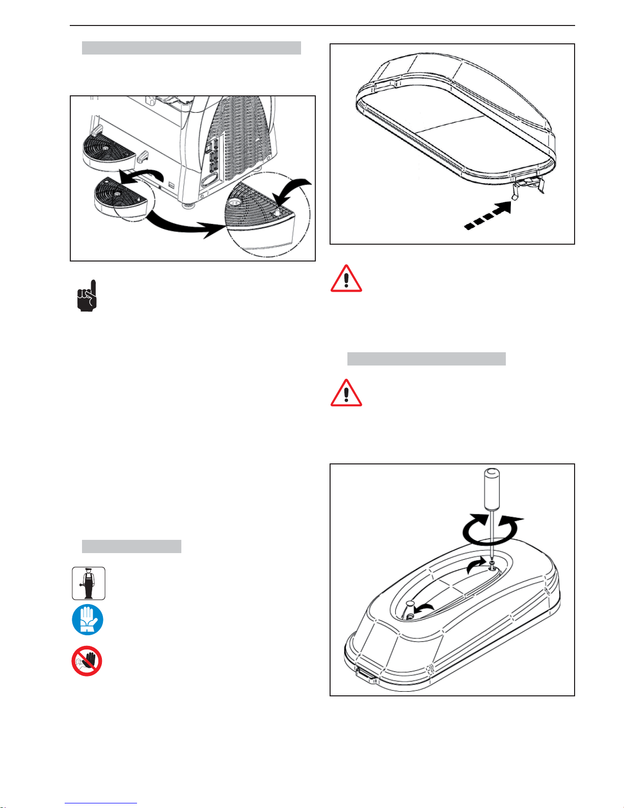
SL310005700 Ed.00 - 04-2011 - 17 _ES-
7.7.
Limpieza de la cubeta receptora de goteo
El vaciado y limpieza de la cubeta receptora de goteo deberá efectuarse diariamente.
Nota. Las operaciones de limpieza deben efectuarse en todas
las cubetas presentes en la máquina.
La cubeta debe ser vaciada y limpiada cada vez que se eleva el
fl otador rojo instalado en la rejilla.
Sujetando fi rmemente el tubo de descarga elevar la cubeta con la rejilla y ex-
traerla tirando hacia afuera.
Lavar la cubeta y la rejilla por separado en agua tibia.
Secar los componentes lavados.
Reinstalar la rejilla sobre la cubeta.
Montar el tubo de descarga en la respectiva abertura.
Instalar la cubeta en su alojamiento y empujarla hacia abajo para fi jarla a la
máquina.
Fig.41
7.8. Tapa luminosa
Del mantenimiento de la tapa luminosa se tiene que encargar
exclusivamente el técnico especializado que tendrá que organizar todas las secuencias operativas y el uso de los medios
adecuados para trabajar respetando rigurosamente las normas vigentes en materia.
Para el operador está prohibido desmontar cualquier componente de la tapa.
Limpiar los contactos de la tapa por un paño mojado y secar muy bien.
Efectuar esta operación cuando la máquina está apagada.
Quitar la bombilla “U” del portalámpara “T” y cambiarla por otra nueva.
Volver a montar la tapa y poner los dos tornillos.
7.8.1. Sustitución de la bombilla
Hay que sustituir la bombilla con el interruptor general en la
posición -0- y con la clavija desenchufada.
Quitar los tapones de protección; separar las dos partes de la tapa luminosa
quitando los dos tornillos; para hacer esta operación utilizar un destornillador
idóneo.
Fig.43
Fig.42
Atención: durante las operaciones de limpieza, poner atención
en evitar de dañar (torcer, romper, etc.) los contactos; eventuales daños podrían causar un malfuncionamiento de la tapa que
no está cubierta por la garantía.
Page 48
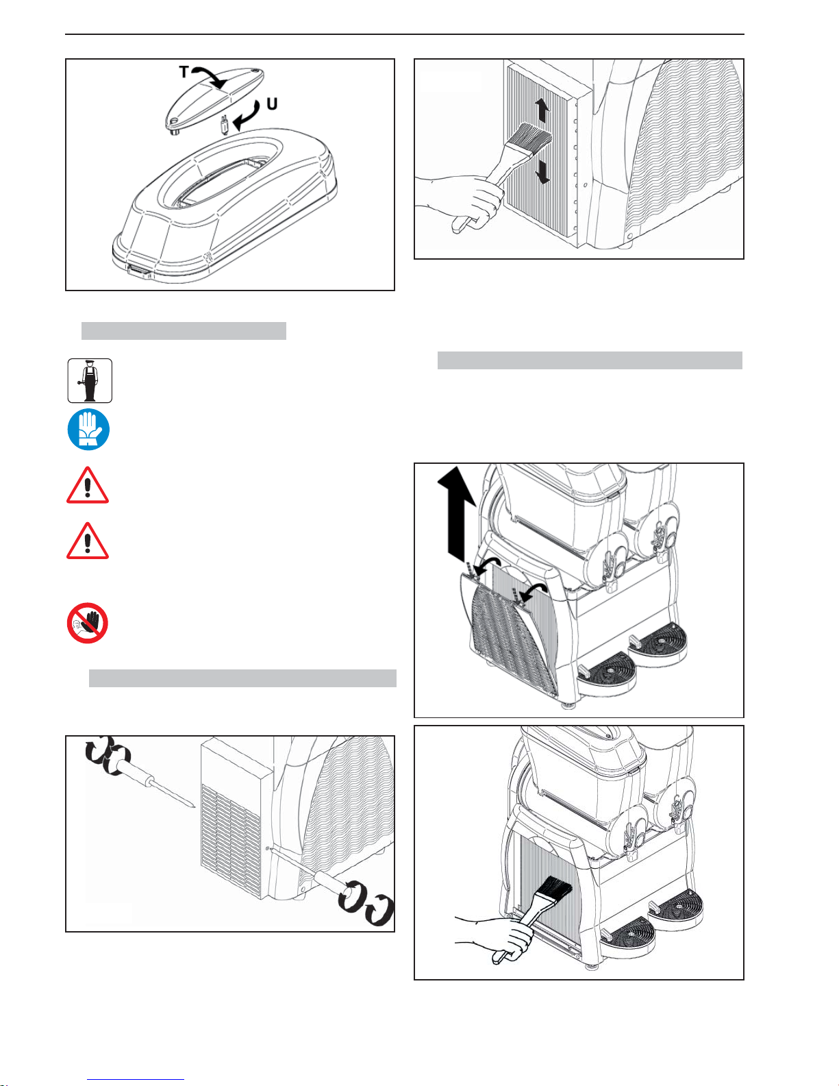
- 18 _ES- SL310005700 Ed.00 - 04-2011
Fig.44
7.9.1. Limpieza del condensador Granitore 1-1FF
Utilizar un destornillador idóneo para desmontar los paneles de protección.
Retirar el panel trasero desenroscando para ello los tornillos que lo fi jan al
bastidor (los tornillos están instalados en los costados, a la derecha y a la
izquierda).
Una vez desmontados los paneles, utilizar un pincel seco para limpiar el polvo
acumulado internamente durante el funcionamiento.
Fig.45
7.9. Limpieza del condensador
La limpieza del condensador es de exclusiva competencia del
técnico especializado, que deberá respetar todas las secuencias operativas y emplear medios adecuados a fi n de observar
rigurosamente las normas vigentes en esta materia.
Efectuar una limpieza periódica del condensador instalado en el
interior de la máquina.
Atención: quitando los paneles se tiene acceso a algunas superfi cies cortantes de la máquina
Un condensador sucio puede comprometer el funcionamiento
de la máquina.
Para obtener acceso al condensador se deben retirar los paneles de protección.
Está prohibido usar la máquina incluso con un solo panel (frontal, trasero o lateral) no correctamente montado. La limpieza del
condensador no debe ser efectuada por el operador.
Después de haber limpiado el condensador reinstalar todos los paneles de
protección.
Fig.46
- después extraiga el panel lateral .
Una vez desmontados los paneles, utilizar un pincel seco para limpiar el polvo
acumulado durante el funcionamiento.
Fig.47
7.9.2.
Limpieza del cond. Granitore 2/2FF-3/3FF
Para quitar elpanel lateral siga los pasos siguientes:
- levante y quite la cubierta del panel lateral.
- desenganche las 2 pestañas presionándolas simultáneamente y estire de l
panel hacia afuera como se ilustra a continuación:
Fig.48
Page 49
SL310005700 Ed.00 - 04-2011 - 19 _ES-
Después de haber limpiado detenidamente el condensador, vuelva a montar
el panel lateral
7.10. Mantenimiento periódico
El aparato tiene que ser controlado periódicamente, por lo menos una vez al año, por un técnico especializado.
Este control periódico sirve para mantener un nivel elevado
de seguridad de todos los componentes instalados y del aparato en cuestión.
Si se desgasta una parte del aparato hay que cambiarla con un nuevo repuesto
original.
Está prohibido utilizar el aparato incluso cuando un solo componente sea defectuoso o esté gastado. Está prohibido el mantenimiento periódico por parte del operador.
8. DESGUACE
Los aparatos eléctricos y electrónicos deben ser eliminados
de conformidad con la Directiva Europea 2002/96/CE.
Estos aparatos NO pueden ser eliminados según el fl ujo normal de
residuos sólidos urbanos , sino deben ser recogidos separadamente para optimizar la recuperación y el reciclado de los materiales que los componen.
El símbolo
del recogedor de basura tachado se encuentra sobre todos los productos para recordar las obligaciones de recogida selectiva.
Observando correctamente todas las disposiciones que se refi eren a la elimina-
ción de los productos viejos, se contribuirá a la protección del medioambiente
Page 50
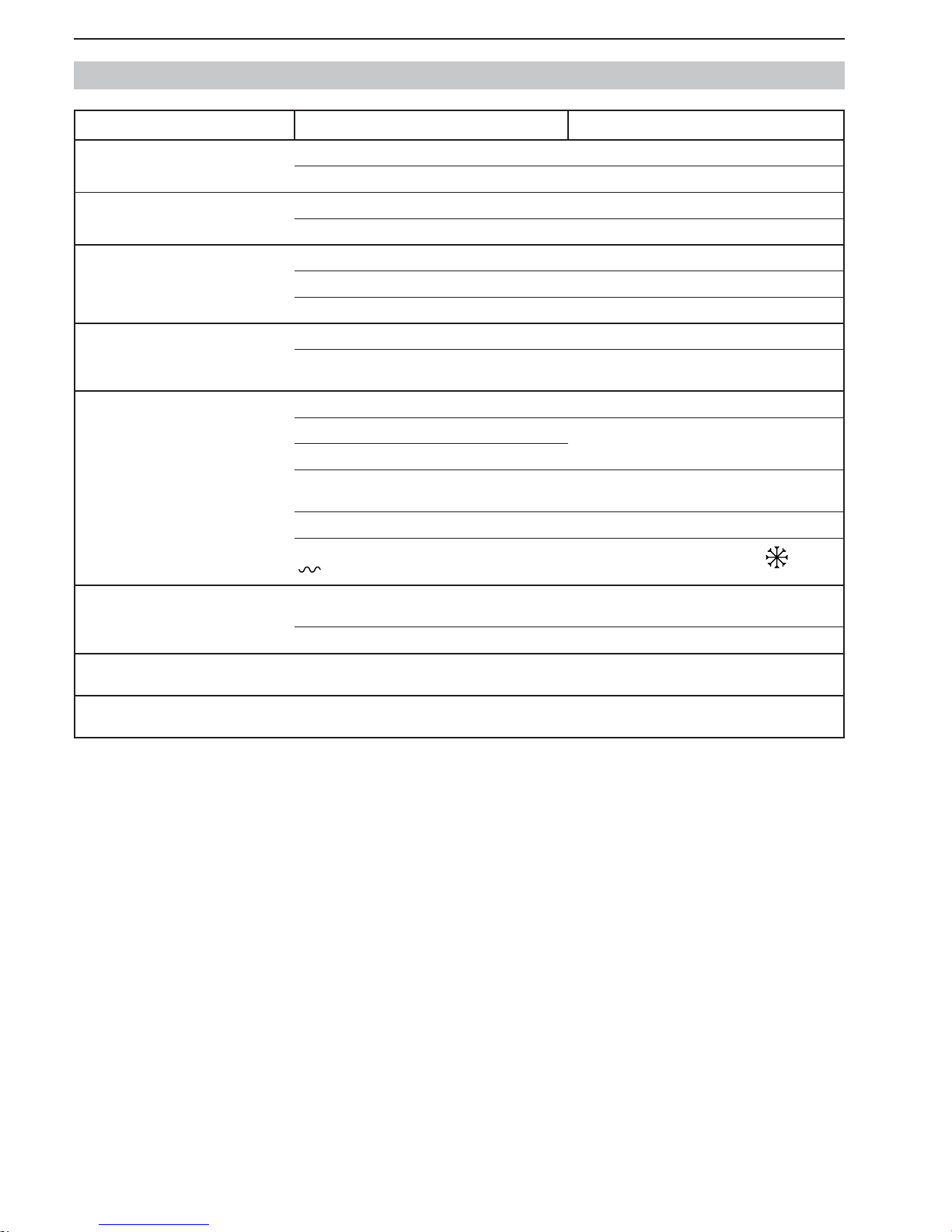
- 20 _ES- SL310005700 Ed.00 - 04-2011
9. PROBLEMAS, CAUSAS Y REMEDIOS
Problemas Causas Remedios
La máquina no se enciende. Interruptor general en Off (en posición “O”). (Cap.6) Disponer el interruptor en posición “I”.
Enchufe no conectado. Conectar el enchufe a una toma adecuada.
Grifo con pérdida. Tapón del grifo no lubricado. (Fig.38) Lubricar tapón.
Tapón dañado. Sustituir el tapón.
Pérdida de producto en la parte trasera del
depósito
Cuba no correctamente montada. (Apart.7.5) Controlar el montaje del depósito.
Guarnición del depósito no lubricada. (Fig.34) Lubricar el depósito de modo correcto
Guarnición dañada Sustituir la junta.
El tornillo sin fi n no gira. Interruptor en posición “O”. (Cap.6) Disponer el interruptor en posición “I”.
Hay bloques de hielo dentro del recipiente. Apague el aparato, deje que se descongele el producto y
compruebe que el producto esté diluido correctamente.
La máquina no produce granizado. Interruptores en posición “O”. (Cap.6) Disponer los interruptores en posición “I”.
Máquina en proximidad de fuentes de calor. Cambiar posición de la máquina. (Cap.5)
Máquina con ventilación insufi ciente.
Condensador sucio. (Apart.7.9) Llamar al técnico especializado para que efectúe la lim-
pieza del condensador.
Regulación errónea de la consistencia. (Apart.6.4) Regular correctamente la consistencia.
Las lengüetas del temporizador están en la posición “
”.
Ponga las lengüetas en la posición “ ” véase el
apartado 6.7
Sinfín ruidoso. Guarnición delantera montada de modo erróneo.
(Fig.32)
Montar correctamente la junta.
Guarnición no lubricada. (Fig.33) Lubricar correctamente la junta.
No sale producto por el grifo Hay bloques de hielo dentro del recipiente. Apague el aparato, deje que se descongele el producto y
compruebe que el producto esté diluido correctamente.
En caso de malfuncionamiento de la máquina no especifi cado en esta tabla o de remedio inapropiado para resolver un determinado problema, sírvase contactar
con un técnico especializado.
Page 51
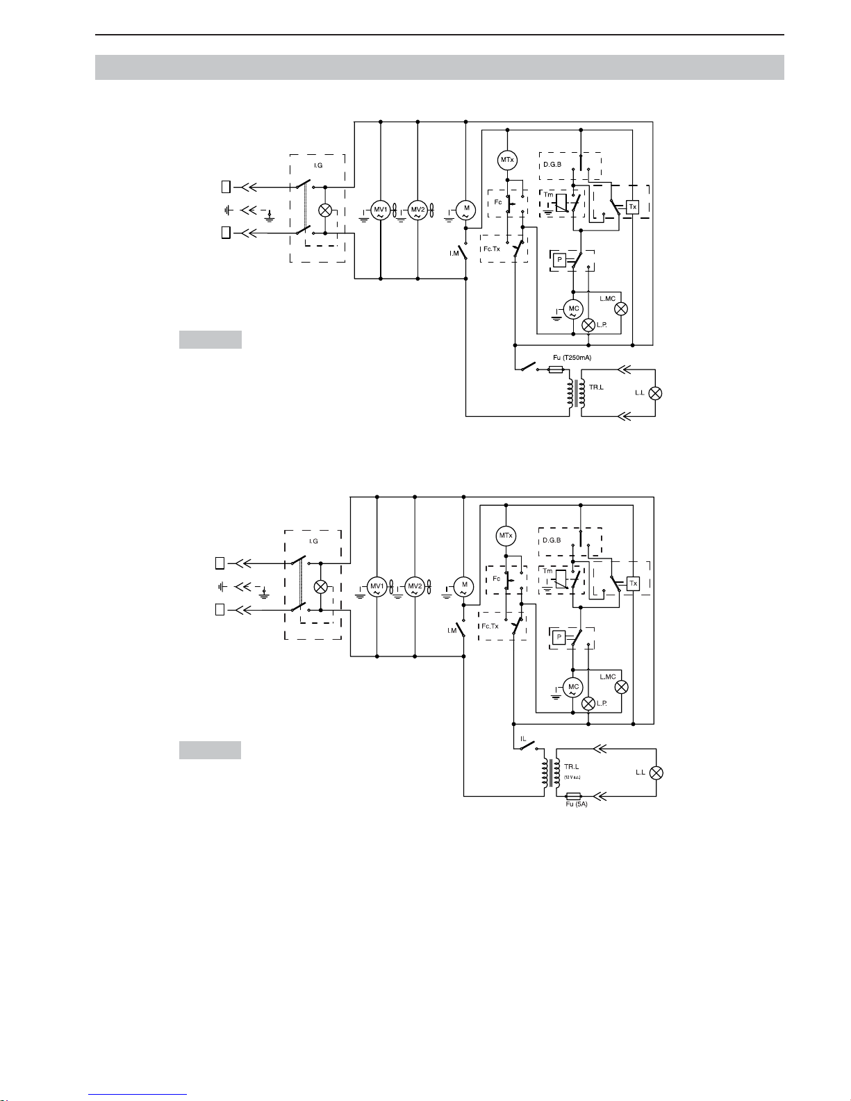
SL310005700 Ed.00 - 04-2011 - 21 _ES-
10. ESQUEMAS ELÉCTRICOS NO ESPECIFICADOS (
GRANIZADORA
1 - 1 FF)
230 Volt
115 Volt
0
I
I
0
IL
0
I
0
I
I0II
t°
F
N
(12 V a.c.)
0
I
I
0
0
I
0
I
I0II
t°
F
N
Page 52
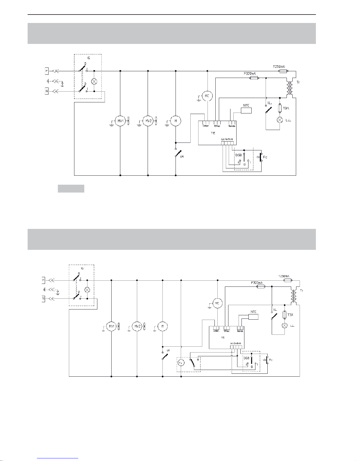
- 22 _ES- SL310005700 Ed.00 - 04-2011
ESQUEMAS ELÉCTRICOS NO ESPECIFICADOS
(GRANIZADORA 1 - 1 FF CON TERMOSTATO ELECTRÓNICO)
ESQUEMAS ELÉCTRICOS NO ESPECIFICADOS
(GRANIZADORA 1 - 1 FF CON TERMOSTATO ELECTRÓNICO +TEMPORIZADOR)
230 Volt
Page 53
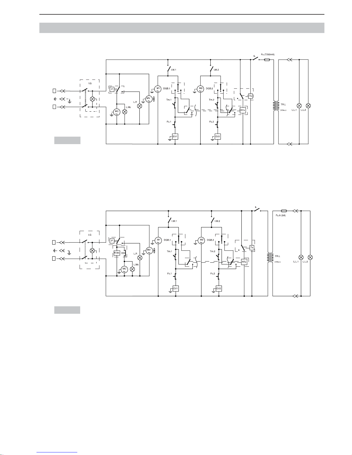
SL310005700 Ed.00 - 04-2011 - 23 _ES-
ESQUEMAS ELÉCTRICOS NO ESPECIFICADOS (
GRANIZADORA
2 - 2FF)
230 Volt
115 Volt
IIIIII
I
0
0
I
0
I
I
0
F
N
IIIIII
I
0
0
I
0
I
I
0
F
N
Page 54
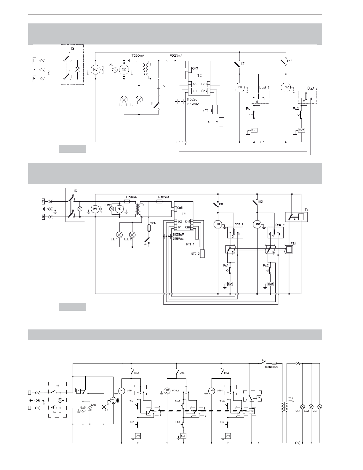
- 24 _ES- SL310005700 Ed.00 - 04-2011
ESQUEMAS ELÉCTRICOS NO ESPECIFICADOS (
GRANIZADORA
3) / 230V
I
0
III IIIIII
I
0
0
I
0
I
I
0
F
N
ESQUEMAS ELÉCTRICOS NO ESPECIFICADOS
(GRANIZADORA 2 - 2 FF CON TERMOSTATO ELECTRÓNICO)
ESQUEMAS ELÉCTRICOS NO ESPECIFICADOS
(GRANIZADORA 2 - 2 FF CON TERMOSTATO ELECTRÓNICO +TEMPORIZADOR)
230 Volt
230 Volt
Page 55
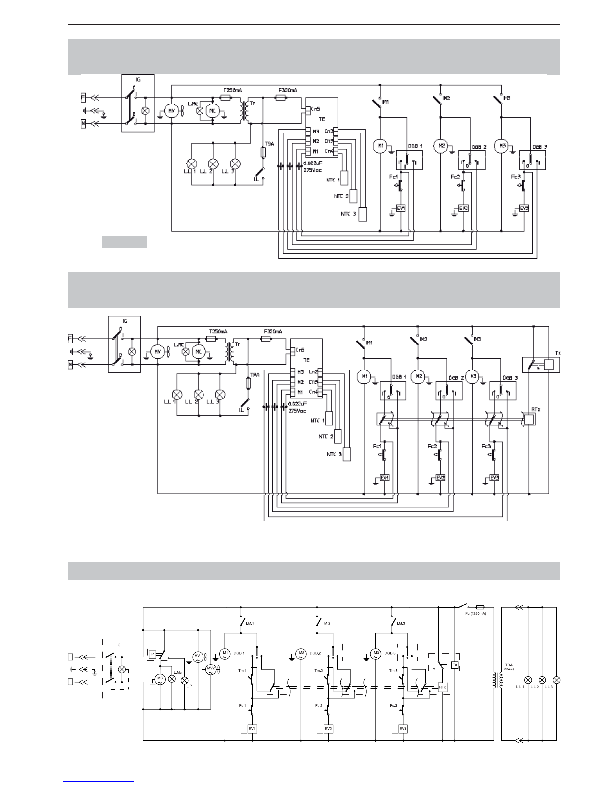
SL310005700 Ed.00 - 04-2011 - 25 _ES-
ESQUEMAS ELÉCTRICOS NO ESPECIFICADOS (
GRANIZADORA
3FF) / 230V
I
0
III IIIIII
I
0
0
I
0
I
I
0
F
N
ESQUEMAS ELÉCTRICOS NO ESPECIFICADOS
(GRANIZADORA 3 CON TERMOSTATO ELECTRÓNICO)
ESQUEMAS ELÉCTRICOS NO ESPECIFICADOS
(GRANIZADORA 3 CON TERMOSTATO ELECTRÓNICO + TEMPORIZADOR)
230 Volt
Page 56
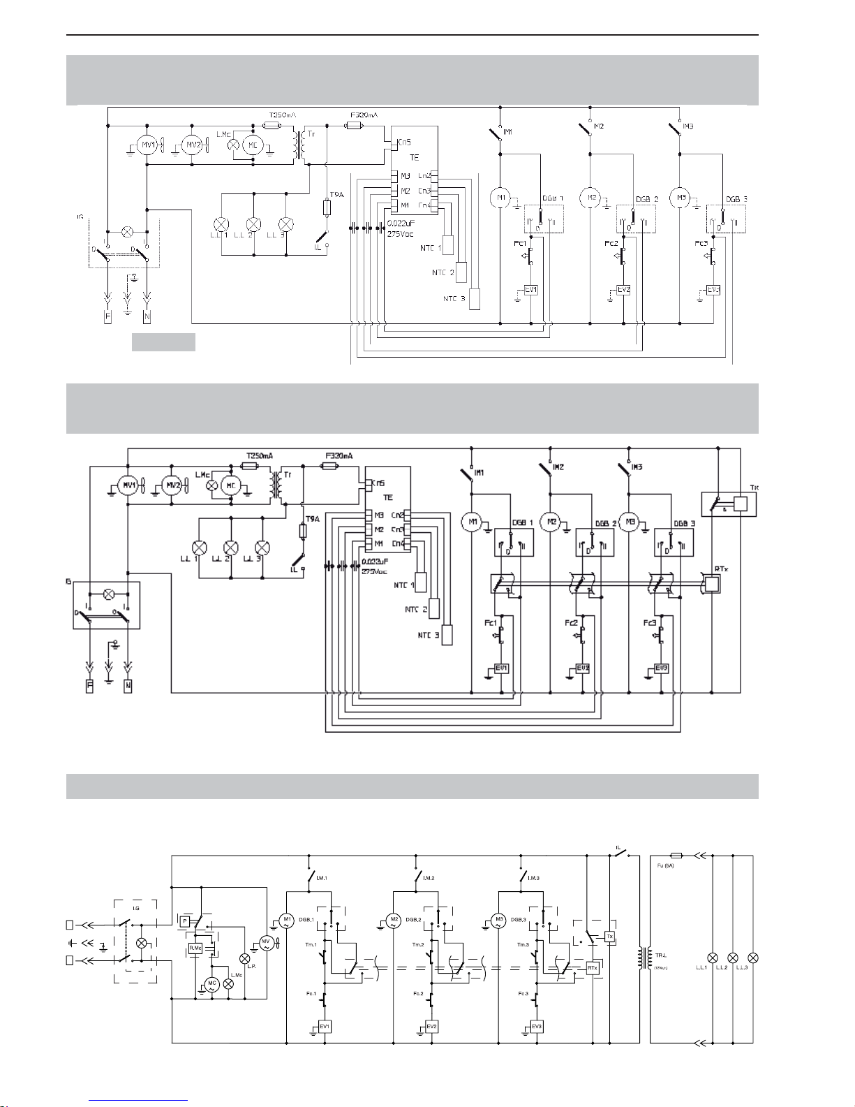
- 26 _ES- SL310005700 Ed.00 - 04-2011
ESQUEMAS ELÉCTRICOS NO ESPECIFICADOS (
GRANIZADORA
3) / 115V
N
F
0
I
I
0
I
0
0
I
IIII IIII I
0
I
ESQUEMAS ELÉCTRICOS NO ESPECIFICADOS
(GRANIZADORA 3FF CON TERMOSTATO ELECTRÓNICO)
ESQUEMAS ELÉCTRICOS NO ESPECIFICADOS
(GRANIZADORA 3FF CON TERMOSTATO ELECTRÓNICO + TEMPORIZADOR)
230 Volt
Page 57
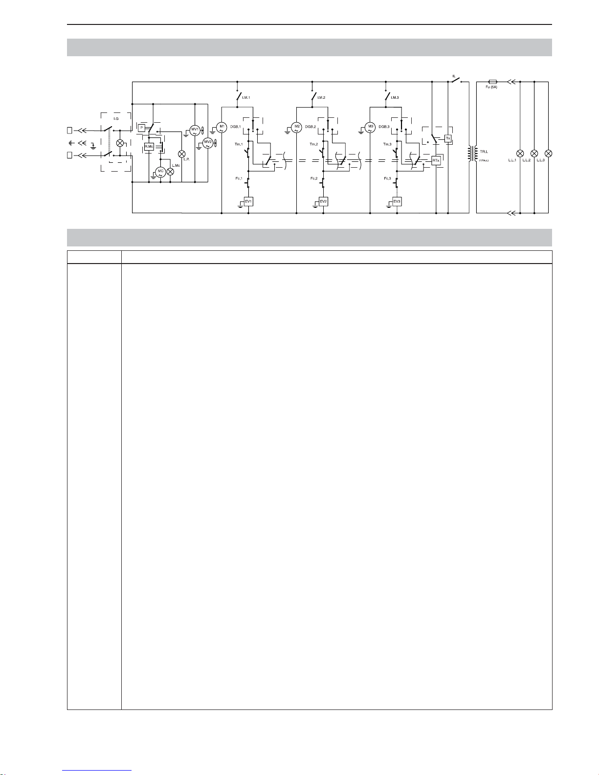
SL310005700 Ed.00 - 04-2011 - 27 _ES-
ESQUEMAS ELÉCTRICOS NO ESPECIFICADOS (
GRANIZADORA
3FF) / 115V
I
0
III IIIIII
I
0
0
I
0
I
I
0
F
N
Sigla Descripción
D.G.B
DGB.1
DGB.2
DGB.3
EV1
EV2
EV3
Fc
Fc.Tx
Fc1
Fc2
Fc3
Fu
FuA
I.G
I.L
I.M
I.M1
I.M2
I.M3
L.L.
L.L.1
L.L.2
L.L.3
L.MC
L.P.
M
M1
M2
M3
MC
MTx
MV
MV1
MV2
N.T.C
N.T.C 1
N.T.C 2
N.T.C 3
P
R.Mc
RTx
TE
Tm
Tm1
Tm2
Tm3
TR
TR.L
Tx
DESVIADOR GRANIZADO/BEBIDA CUBA
DESVIADOR GRANIZADO/BEBIDA CUBA 1
DESVIADOR GRANIZADO/BEBIDA CUBA 2
DESVIADOR GRANIZADO/BEBIDA CUBA 3
ELECTROVÁLVULA CUBA 1
ELECTROVÁLVULA CUBA 2
ELECTROVÁLVULA CUBA 3
FINAL DE CARRERA REGULACIÓN CUBA
FINAL DE CARRERA TEMPORIZADOR
FINAL DE CARRERA REGULACIÓN CUBA 1
FINAL DE CARRERA REGULACIÓN CUBA 2
FINAL DE CARRERA REGULACIÓN CUBA 3
FUSIBLE
FUSIBLE AUXILIAR
INTERRUPTOR GENERAL
INTERRUPTOR TAPA LUMINOSA
INTERRUPTOR MOTOR MEZCLADOR CUBA
INTERRUPTOR MOTOR MEZCLADOR CUBA 1
INTERRUPTOR MOTOR MEZCLADOR CUBA 2
INTERRUPTOR MOTOR MEZCLADOR CUBA 3
LÁMPARA TAP A LUMINOSA
LÁMPARA TAPA LUMINOSA CUBA 1
LÁMPARA TAPA LUMINOSA CUBA 2
LÁMPARA TAPA LUMINOSA CUBA 3
LÁMPARA COMPRESOR
LÁMPARA PRESOSTATO
MOTOR MEZCLADOR
MOTOR MEZCLADOR CUBA 1
MOTOR MEZCLADOR CUBA 2
MOTOR MEZCLADOR CUBA 3
MOTOR COMPRESOR
MOTOR TEMPORIZADOR
MOTOR VENTILADOR
MOTOR VENTILADOR 1
MOTOR VENTILADOR 2
SONDA TEMPERATURA CUBA
SONDA TEMPERATURA CUBA 1
SONDA TEMPERATURA CUBA 2
SONDA TEMPERATURA CUBA 3
PRESOSTATO
RELÉ COMPRESOR
RELÉ DEL TEMPORIZADOR
TERMOSTATO ELECTRÓNICO
TERMOSTATO CUBA
TERMOSTATO CUBA 1
TERMOSTATO CUBA 2
TERMOSTATO CUBA 3
TRANFORMADOR
TRANFORMADOR
TEMPORIZADOR
LEYENDA
Page 58

Page 59
Pol.Ind. Rafelcofer - C/ Tramuntana, 10
46716 - RAFELCOFER (Valencia - España)
e-mail l [email protected]
Tel. 96 280 11 12 - Fax 96 289 94 10
TARJETA DE GARANTÍA
DATOS DEL CLIENTE
Nombre:
Domicilio: Nº:
Localidad: Provincia:
C.P.: Teléfono: Fax:
MODELO: Nº MATRÍCULA:
FIRMA Y/O SELLO DEL CLIENTE:
FECHA DE INSTALACIÓN: __ __ / __ __ / __ __ __ __
GARANTÍA
El presente certifi cado, garantiza contra cualquier defecto de fabricación y en las condiciones que se especifi can más adelante, el
producto cuyos datos de identifi cación fi guran en el presente documento. Esta garantía se concede con carácter personal e intransfe-
rible a favor del comprador.
CONDICIONES
1. LA PRESENTE GARANTÍA TIENE VALIDEZ SOLAMENTE PARA MÁQUINAS VENDIDAS E INSTALADAS EN
EL TERRITORIO ESPAÑOL.
2. La presente garantía cubre la reposición de piezas afectadas por un defecto de fabricación. Quedan excluidos desplaza mientos y mano de obra.
3. Las piezas defectuosas cubiertas por la garantía deberán ser remitidas a nuestras instalaciones en el plazo máximo de un
mes desde la fecha del envío de las piezas de repuesto. De lo contrario se facturarán al cliente.
4. El plazo de la garantía será de 1 año a partir de la instalación y máximo de 2 años a partir de la fecha de adquisición del
producto. El compresor y la motorreductora, en las máquinas que lo lleven, tendrán 2 años de garantía a partir de la fecha
de instalación.
5. Este documento de garantía no cubrirá los defectos que sean producidos por una instalación incorrecta o defi ciente, no
seguimiento de las instrucciones de utilización y mantenimiento o circunstancias de otra índole no imputables a defectos
de fabricación del producto.
6. Para la validez de la presente garantía será imprescindible el envío de este documento debidamente cumplimentado. El
pedido de piezas en garantía deberá ir acompañado de fotocopia de la tarjeta de garantía o número de matrícula de la má quina o fotocopia de la factura de compra.
7. Cualquier reclamación que se efectúe al amparo de la presente garantía podrá ser examinada y verifi cada por el personal
técnico del garante
8. La garantía no altera las condiciones de venta convenidas entre el garante y el comprador.
EJEMPLAR PARA EL CLIENTE
Page 60

Page 61
Pol.Ind. Rafelcofer - C/ Tramuntana, 10
46716 - RAFELCOFER (Valencia - España)
e-mail l [email protected]
Tel. 96 280 11 12 - Fax 96 289 94 10
TARJETA DE GARANTÍA
DATOS DEL CLIENTE
Nombre:
Domicilio: Nº:
Localidad: Provincia:
C.P.: Teléfono: Fax:
MODELO: Nº MATRÍCULA:
FIRMA Y/O SELLO DEL CLIENTE:
FECHA DE INSTALACIÓN: __ __ / __ __ / __ __ __ __
GARANTÍA
El presente certifi cado, garantiza contra cualquier defecto de fabricación y en las condiciones que se especifi can más adelante, el
producto cuyos datos de identifi cación fi guran en el presente documento. Esta garantía se concede con carácter personal e intransfe-
rible a favor del comprador.
CONDICIONES
1. LA PRESENTE GARANTÍA TIENE VALIDEZ SOLAMENTE PARA MÁQUINAS VENDIDAS E INSTALADAS EN
EL TERRITORIO ESPAÑOL.
2. La presente garantía cubre la reposición de piezas afectadas por un defecto de fabricación. Quedan excluidos desplaza mientos y mano de obra.
3. Las piezas defectuosas cubiertas por la garantía deberán ser remitidas a nuestras instalaciones en el plazo máximo de un
mes desde la fecha del envío de las piezas de repuesto. De lo contrario se facturarán al cliente.
4. El plazo de la garantía será de 1 año a partir de la instalación y máximo de 2 años a partir de la fecha de adquisición del
producto. El compresor y la motorreductora, en las máquinas que lo lleven, tendrán 2 años de garantía a partir de la fecha
de instalación.
5. Este documento de garantía no cubrirá los defectos que sean producidos por una instalación incorrecta o defi ciente, no
seguimiento de las instrucciones de utilización y mantenimiento o circunstancias de otra índole no imputables a defectos
de fabricación del producto.
6. Para la validez de la presente garantía será imprescindible el envío de este documento debidamente cumplimentado. El
pedido de piezas en garantía deberá ir acompañado de fotocopia de la tarjeta de garantía o número de matrícula de la má quina o fotocopia de la factura de compra.
7. Cualquier reclamación que se efectúe al amparo de la presente garantía podrá ser examinada y verifi cada por el personal
técnico del garante
8. La garantía no altera las condiciones de venta convenidas entre el garante y el comprador.
EJEMPLAR PARA SENCOTEL
Page 62

Page 63

Page 64

- 2 _EN- SL320005700 Ed.00 - 04-2011
INDEX
1. GENERAL INFORMATION ..........................3
1.1. Manufacturer ........................................................3
1.2. Authorized persons ..............................................3
1.3. Layout of the manual ............................................3
1.3.1. Purpose and contents. ...................................3
1.3.2. Who must read the manual. ..........................3
1.3.3. How to keep the manual. ...............................3
1.3.4. Symbols used. ...............................................3
2. MACHINE DESCRIPTION ...........................4
2.1. Use of the machine ..............................................4
2.2. Main components .................................................4
2.3. Technical Data ......................................................4
2.4. Control panel description and functions ...............5
3. SAFETY .......................................................6
3.1. General safety rules .............................................6
3.2. Stop functions ......................................................6
3.3. Plates ...................................................................6
4. HANDLING AND STORAGE .......................6
4.1. Packaging ............................................................6
4.2. Conveyance and handling ....................................7
4.3. Storage .................................................................7
5. INSTALLATION ...........................................7
5.1. List of accessories provided .................................7
5.2. Installation-Positioning .........................................7
5.3. Disposal of packing materials ..............................8
5.4. Electrical connection ............................................8
6. OPERATION ................................................8
6.1 Preparing the product ...........................................8
6.2 Starting a Granitore ..............................................9
6.3. Starting a Granita machine 1
(electronic thermostat) .......................................10
6.4. Starting a Granita machine 2/3
(electronic thermostat) .......................................10
6.5. Adjusting granita consistency .............................11
6.6. Dispensing granita .............................................11
6.7. Emergency situations .........................................12
6.8. Accessory (Optional) (Locking System) .............12
6.9. Optionals (Timer)................................................12
6.9.1. Setting the current time ..................................12
6.9.2. Operating the machine with the timer. ............12
7. CLEANING AND MAINTENANCE ............13
7.1. Emptying the bowls ............................................13
7.2. Disassembling the dispensing tap ......................14
7.3. Removing the bowl and the lid ...........................14
7.4. Washing and sanitizing the components ............15
7.5. Reassembling the washed components. ...........15
7.6. Rinsing cycle ......................................................16
7.7. Cleaning the drip tray .........................................17
7.8. Lighted lid ...........................................................17
7.8.1. Bulb replacement ...........................................17
7.9. Cleaning the condenser .....................................18
7.9.1. Cleaning the Granitore 1/1FF condenser ..........18
7.9.2. Cleaning Granitore 2/2 FF - 3/3 FF cond. ......18
7.10. Periodic maintenance .........................................19
8. SCRAPPING ..............................................19
9. TROUBLESHOOTING ...............................20
10. BASIC WIRING DIAGRAMS .....................21
Page 65
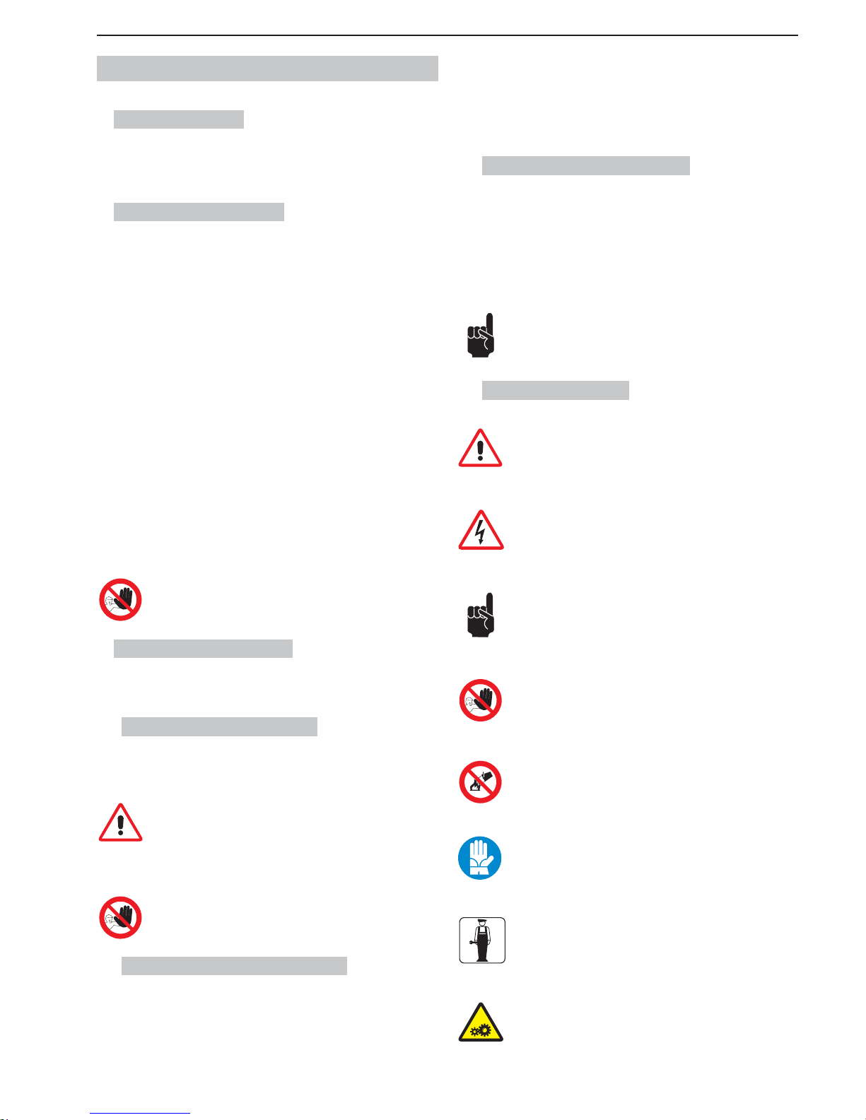
SL320005700 Ed.00 - 04-2011 - 3 _EN-
1. GENERAL INFORMATION
1.1. Manufacturer
The manufacturer’s details are shown on the identifi cation plate, illus-
trated on fi rst and/or last page of the manual.
1.2. Authorized persons
Two types of persons may access the machine for different purposes.
User
A person who has adequate technical training to prepare the products the machine uses to dispense granita, in observance of current standards of hygiene.
After reading this manual, he will be capable of:
• carrying out normal product loading and/or replacement operations;
• properly dispensing the product;
• cleaning and sanitizing the machine.
Specialized technician
A person who has examined this manual and has specifi c training in the instal-
lation, use and servicing of the granita machine:
• he must be able to carry out repairs in the event of serious faults and be well
acquainted with this manual and all the information regarding safety;
• he must be able to understand the contents of the manual and correctly
interpret drawings and diagrams;
• he must be familiar with the most important sanitary, accident prevention,
technological and safety standards;
• he must have specifi c experience in servicing granita machines;
• he must know how to behave in case of emergency, where to fi nd individual
safety equipment and how to use it properly.
Persons who do not meet the above requirements must not be
allowed to use the machine.
1.3. Layout of the manual
The Purchaser must very carefully read the information contained in this manual.
1.3.1. Purpose and contents
The purpose of this manual is to provide the Purchaser with all the necessary
information regarding the installation, maintenance and use of the granita machine.
Before carrying out any operation on the machine, users and
specialized technicians must carefully read the instructions
herein.
Should you have any doubts as to the correct interpretation of these instructions, contact the manufacturer to request the necessary explanations.
You should not carry out any type of operation until you have
read and thoroughly understood the contents of this manual.
1.3.2. Who must read the manual
This manual is aimed at users and specialized technicians.
Users must not attempt to carry out any operations restricted to qualifi ed
technicians.
The manufacturer will not be liable for any damage or injury caused as a result
of failure to comply with this rule.
The instruction manual is an integral part of the product purchased and must
therefore be handed over to any subsequent owners.
1.3.3. How to keep the manual
This instruction manual must be kept in the immediate vicinity of the machine.
Due precautions should be taken to ensure that the manual is maintained intact
and legible over time:
• Use the manual in such a way as to avoid damaging any of its contents.
• Do not for any reason remove, tear or rewrite parts of the manual.
• Keep the manual in a place that is protected against humidity and heat in
order to preserve the quality of the print and the legibility of all its parts.
If the present instruction manual is damaged or lost, another
copy should be immediately requested from the manufacturer
or authorized distributor in the user’s country.
1.3.4. Symbols used
GENERAL DANGER WARNING
It indicates a danger which may also place the User at mortal risk.
In such cases utmost care is required and every precaution must be
taken in order to operate safely.
DANGER OF ELECTROCUTION
It warns the personnel concerned that the operation described may
result in an electric shock unless all the necessary safety precautions are taken
IMPORTANT
It indicates a cautionary note, a note about key functions or useful
information.
Very close attention should be paid to the portions of text marked
with this symbol
PROHIBITED
This symbol is used to indicate operations that must absolutely be
avoided since they create hazards for the User and any other individuals present in the vicinity.
DO NOT EXTINGUISH FIRES WITH WATER
The presence of this symbol warns against attempting to extinguish
fi res with water or any substance containing water.
PERSONAL PROTECTION
When this symbol appears alongside a description it means that
personal safety equipment must be used, as there is an implicit risk
of accidents.
SPECIALIZED TECHNICIAN
It identifi es operations that may be performed only by qualifi ed tech-
nical personnel.
MOVING MACHINE PARTS
It identifi es the danger due to moving parts existing in the machine.
Turn off the machine before carrying out any operation.
Page 66
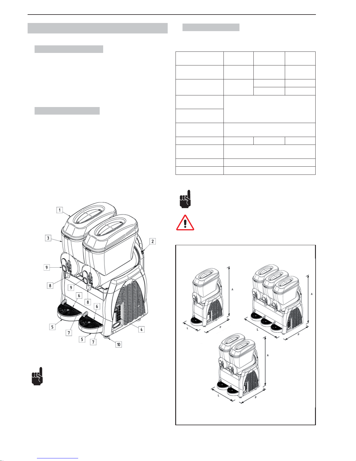
- 4 _EN- SL320005700 Ed.00 - 04-2011
2. MACHINE DESCRIPTION
2.1. Use of the machine
The professional machine you are using is suitable for making slush drinks
and cold beverages. If used with dairy-based products and/or when envisaged
by law in according to the type of product used, it must be equipped with the
optional extra of a “temperature gauge” for the product in the bowl. It is also
obligatory to comply with the current regulations and standards concerning the
products used.
2.2. Main components
The main components making up the machine are:
1 Bowl lid
2 Thickness regulator
3 Bowl
4 Control panel
5 Drip tray
6 Grid
7 Float (overfl ow indicator)
8 Product dispenser
9 Product dispensing lever
10 Feet
2.3. Technical Data
The technical data and features are listed below
Model
Granitore 1
Granitore 1 FF
Granitore 2
Granitore 2 FF
Granitore 3
Granitore 3 FF
Dimensions
L x P x H (mm).
27 x 52 x 81 47 x 52 x 81 67 x 52 x 81
Maximum Electrical
Input (W)
29
47 68
52 70
Potencia máxima consumida (W)
See rating plate on side of machine
Operating voltage
(V).
Operating temperature. Min. 20°C
Max. 32°C
Number of bowls. 1 2 3
Capacity of each
bowl (l.)
12
Sound pressure level << 70 dB
A
Class. N
Fig.2
To make the instructions easier to read, the following abbreviations are used herein:
Granitore 1, identifi es a Granita machine with one (1) bowl;
Granitore 2, identifi es a Granita machine with two (2) bowls;
Granitore 3, identifi es a Granita machine with three (3) bowls;
Granitore 1 FF, identifi es a Granita machine with one (1) bowl and Fast Freeze
refrigeration system;
Granitore 2 FF, identifi es a Granita machine with two (2) bowls and Fast Freeze
refrigeration system;
Granitore 3 FF, identifi es a Granita machine with three (3) bowls and Fast
Freeze refrigeration system.
Note: The manufacturer reserves the right to make changes to
the machine without notice.
Important! Any changes and/or additions of accessories must
be explicitly approved and implemented by the Manufacturer.
Fig.1
Page 67
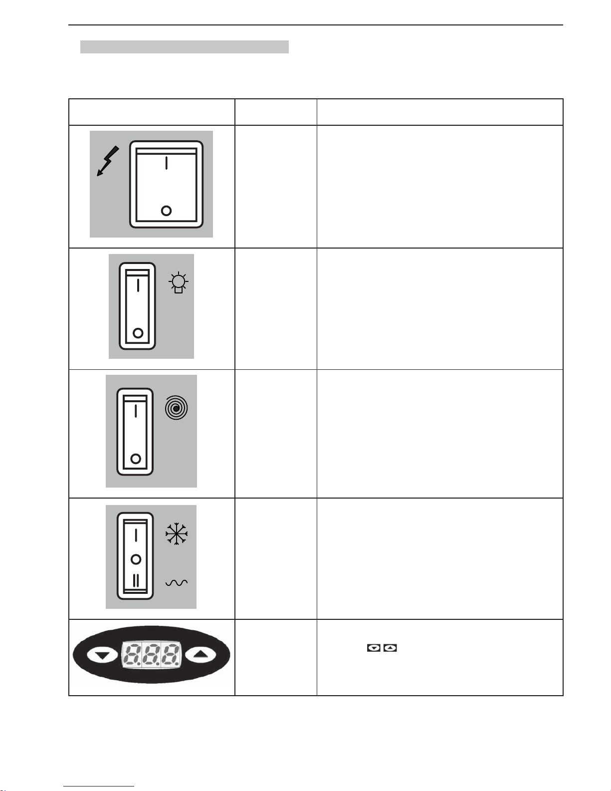
SL320005700 Ed.00 - 04-2011 - 5 _EN-
2.4. Control panel description and functions
The machine controls are located on the side control panel.
COMMAND MODEL FUNCTION
ALL
Main switch: its function is to command:
- the starting of the machine;
- the switching off of all the functions present on the machine.
ALL
Lid light switch: to turn on/off light (if present) on the bowl lids.
ALL
Bowl mixing switch (one for each bowl): it is used to switch on and off the
gearmotor that drives the auger for mixing the product in the respective
bowl.
ALL
Refrigeration system changeover switch (one for each bowl):
- in position “0”, the refrigeration system is deactivated;
- in position “I”, the refrigeration system is activated for the production of
granitas;
- in position “II”, the refrigeration system is activated for the production of
cold drinks.
ALL VERSIONS WITH
ELECTRONIC THER-
MOSTAT
Electronic thermostat:
- This shows the temperature of the product inside the tank and using
the keys
, it is possible to change the temperature of the drink
when the machine is operating in “cold drinks” mode.
Page 68
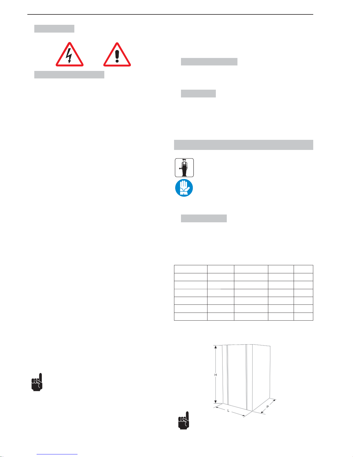
- 6 _EN- SL320005700 Ed.00 - 04-2011
3. SAFETY
3.1. General safety rules
• Carefully read the whole instruction manual.
• The connection to the electricity mains must comply with the current safety
standards in the user’s country.
• The machine must be connected to an electric outlet that is:
- compatible with the plug provided with the machine;
- of dimensions conforming to the data shown on the rating plate on the
side of the machine.
- properly grounded;
- connected to a system provided with a differential switch and circuit
breaker.
• The power cord must not be:
- allowed to come into contact with any kind of liquid: danger of electric
shocks and/or fi re;
- crushed and/or brought into contact with sharp surfaces;
- used to move the machine;
- used if it shows any damage;
- handled with damp or wet hands;
- wound into a coil when the machine is on.
- tampered with.
• DO NOT:
- install the machine in a manner other than that described in Chap. 5.
- Install the machine in a place where it may be exposed to sprays of water.
- use the machine near infl ammable and/or explosive substances.
- leave plastic bags, polystyrene, nails etc. within children’s reach, since
they are potential sources of danger.
- allow children to play or stay near the machine.
- use spare parts other than those recommended by the manufacturer.
- make any technical changes to the machine.
- immerse the machine in any kind of liquid.
- spray water on the machine to wash it.
- use the machine other than as directed in this manual.
- use the machine when not in full possession of your mental and physical
faculties: under the infl uence of drugs, alcohol, etc.
- install the machine on top of other equipment.
- use the machine in an explosive or aggressive atmosphere or in the presence
of a high concentration of dust or oily substances suspended in the air;
- use the machine in a place where there is a risk of fi re;
- use the machine to dispense substances that are not compatible with the
machine’s specifi cations;
• Before cleaning the machine, make sure that it is unplugged; do not clean
the machine with gasoline and/or solvents of any kind.
• Repair work may be performed only by a Service Center authorized by the
Manufacturer and/or specialized, trained personnel.
• Do not obstruct the grill vents on the side of the machine.
• Do not site the machine near heating equipment (stoves or radiators).
• In case of fi re, use carbon dioxide (CO2) extinguishers. Do not use water or
powder extinguishers.
In the event of improper use, all warranty rights will be forfeited
and the manufacturer will accept no liability for injury or damage to persons and/or property.
The following are to be considered improper use:
- any use other than the intended use and/or with methods other than those
described herein;
- any operation on the machine that is in contrast with the directions provided
herein;
- use of the machine after any components have been tampered with and/or
safety devices have been changed;
- use of the machine after it has undergone repair with components not authorized by the manufacturer;
- outdoor installation of the machine.
3.2. Stop functions
The machine is shut down by turning off the main switch.
3.3. Plates
NONE OF THE PLATES OR LABELS APPLIED ON THE MACHINE MUST
BE REMOVED, COVERED OR DAMAGED, ESPECIALLY THOSE RELATING TO SAFETY.
4. HANDLING AND STORAGE
All the operations described in chapter 4 may be carried out
exclusively by technicians who are also specialized in the
lifting and handling of packed or unpacked machines. They
must organize all the operational sequences and use suitable
equipment, according to the characteristics and weight of the
object to be handled and in strict compliance with the applicable regulations currently in force.
4.1. Packaging
The machine is shipped ready for use in a cardboard box. The cardboard box
comprises a base and a cover, which are secured together with two nylon
straps.
DIMENSIONS AND WEIGHT OF PACKING CONTAINER
Width (L) Depth (P) Height (H) Weight
Granitore 1 340 mm 540 mm 930 mm 32 kg
Granitore 1 FF 340 mm 540 mm 930 mm 32 kg
Granitore 2 560 mm 540 mm 930 mm 52 kg
Granitore 2 FF 560 mm 540 mm 930 mm 57 kg
Granitore 3 770 mm 540 mm 930 mm 72 kg
Granitore 3 FF 770 mm 540 mm 930 mm 74 kg
Note: the dimensions and weight of the packing container are
approximate.
Fig.3
Page 69
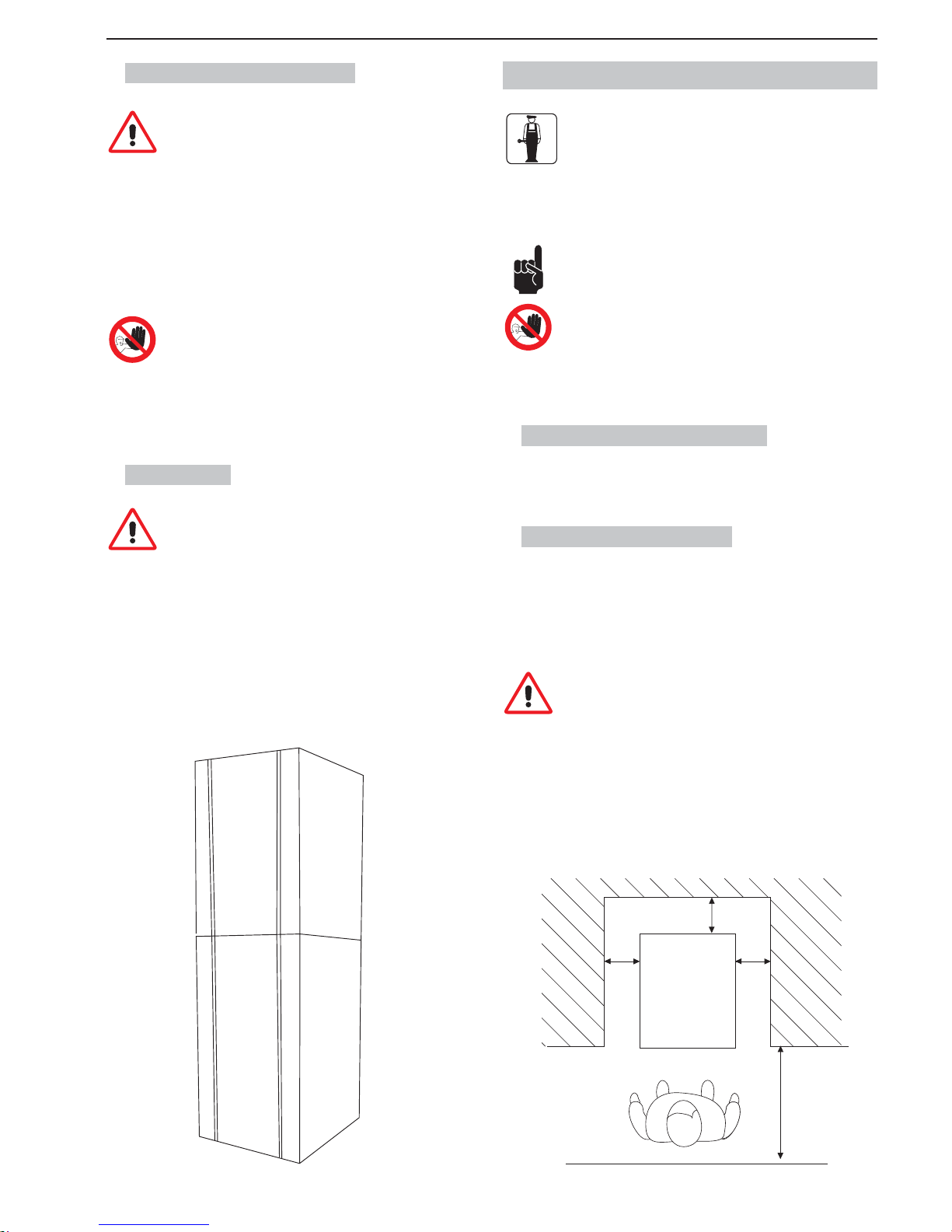
SL320005700 Ed.00 - 04-2011 - 7 _EN-
4.2. Conveyance and handling
Make sure that no one is stationed within range of lifting and
handling operations. In diffi cult conditions, specialized person-
nel should be appointed to oversee the movements of the machine.
Manual handling of the machine requires at least two people.
The machine must be moved into an upright position, only after every
bowl has been emptied of product.
Lift the box and carefully convey it, avoiding routes with obstacles. Pay attention
to the overall dimensions and any parts sticking out.
Warning: do not make any additional cuts on the packing container.
The WARRANTY does not cover damage caused to the machine during its
conveyance and handling.
The Purchaser will bear the cost of repairing or replacing damaged parts
4.3. Storage
Before the machine is placed in storage and whenever the machine is started up again after a period of storage, it must be
thoroughly cleaned and sanitized.
Warning: do not store more than two machines stacked on top of one
another.
If the machine is to remain unused for a long period of time, due precautions
must be taken with respect to the place and duration of storage:
• store the machine in a closed place;
• protect the machine from shocks and stresses;
• protect the machine from humidity and large temperature fl uctuations;
• prevent the machine from coming into contact with corrosive substances.
MAX
MAX
Fig.4
5. INSTALLATION
All of the operations described in chapter 5 may be carried
out exclusively by specialized technicians, who must organize all the operational sequences and use suitable equipment, in strict compliance with the applicable regulations
currently in force.
The machine must be installed indoors in a well-lit and well-ventilated room with
a fi rm, solid, level fl oor (slope less than 2°).
The machine is of the attended type, and must be installed in
places where it can be monitored by trained personnel.
Warning: it is forbidden to install the machine in a place where
it may be reached, touched and/or operated by persons other
than those specifi ed in section 1.2.
The machine may only operate in places with an ambient temperature ranging
between 20°C and 32°C.
5.1. List of accessories provided
• Vaseline: to lubricate all of the parts indicated in this manual after washing
and sanitization operations.
5.2. Installation-Positioning
The installer must check that:
• the site has been duly prepared for machine installation;
• the surface the machine will be installed on is fi rm, fl at and solid;
• the room is adequately lit, ventilated and hygienic and an electric outlet is
within easy reach.
Adequate clearance must be left around the machine to enable
personnel to work without any constraints and also to leave the
work area immediately in case of need.
Figure 5 shows the minimum clearances for installation
150 cm
60 inches
25 cm
10 inches
25 cm
10 inches
25 cm
10 inches
Fig.5
Page 70
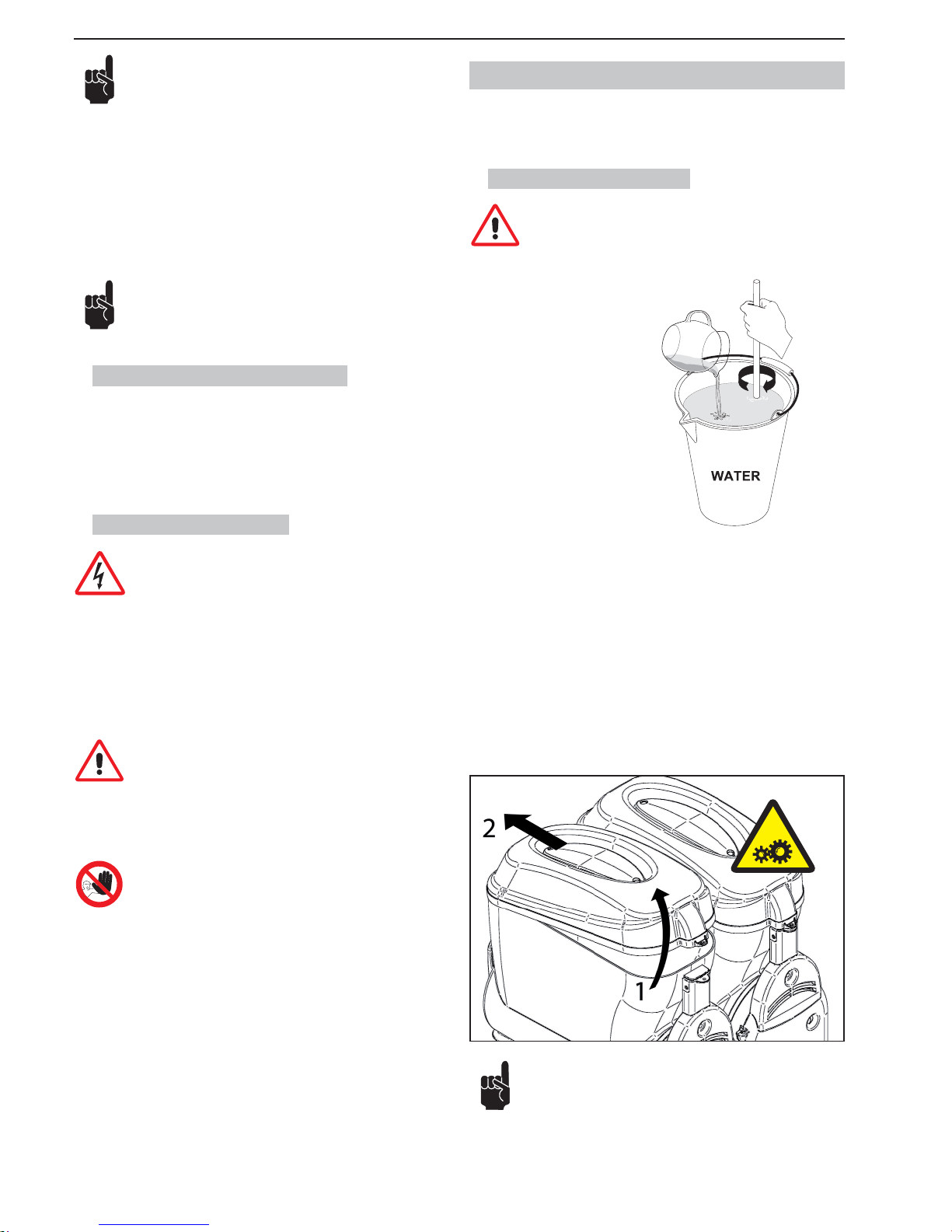
- 8 _EN- SL320005700 Ed.00 - 04-2011
Note: Leave a 25 cm (10 inches) space in the upper part.
Fig. 5 shows the clearances required for access:
• the control panel on the right side;
• machine parts so that they may be serviced in the event of a fault.
After positioning the packing container in the vicinity of the installation site, pro-
ceed as follows:
1. cut the straps securing the box;
2. lift the cardboard box;
3. then lift the machine and position it on the prepared site.
Before the machine is used for the first time, its components must
undergo thorough cleaning and the parts that will come into contact with the granita must be sanitized; for further details see the
relevant section herein.
5.3. Disposal of packing materials
After opening the box, make sure to separate the packing materials according
to type and dispose of them in accordance with the current regulations in the
user’s country.
We recommend keeping the box for future conveyance or transport
5.4. Electrical connection
This job may be performed only by specialized technical personnel.
Before plugging in the machine, make sure that the main switch is on “0”.
The Purchaser is responsible for making the electrical connection.
The machine must be connected to the electricity mains by means of the plug
fi tted on the power cord. Be sure to comply with:
• the technical regulations and standards in force at the time of installation;
• the data shown on the rating plate on the side of the machine.
Warning: the electric outlet must be situated in a place easily
within reach of the user, so that no effort is required in order
to disconnect the machine from the power supply when necessary.
If the power cord is damaged, you must have it replaced either by the
manufacturer or a specialized technician
It is forbidden:
• to use extension cords of any type;
• to replace the original plug;
• to use adaptors.
6. OPERATION
Before the machine may be started up for the fi rst time, specialized tech-
nical personnel must check that it functions properly.
6.1 Preparing the product
Warning: Product may be poured into the bowl only when the
machine is off and unplugged.
Fig.6
Dilute and mix the CONCENTRATE with W ATER in a suitable container, following the manufacturer’s directions. THE MIXTURE OBTAINED MUST HAVE A
MINIMUM SUGAR CONTENT OF 13° BRIX - A lower concentration may damage the augers and/or gearmotors.
NEVER USE ONLY WATER
To remove the lid from the bowl, follow these instructions:
1 lift the rear part of the lid;
2 extract the lid from the retainer placed in the front side.
Warning: do not force the lid opening in case of diffi culty.
Fig.7
Page 71
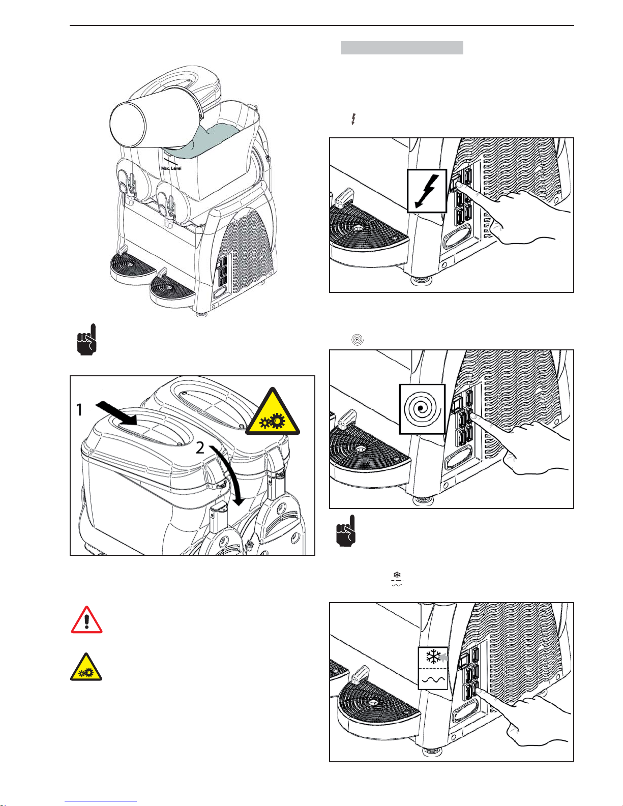
SL320005700 Ed.00 - 04-2011 - 9 _EN-
Pour the product into the bowl taking care that it never goes
above the max level.
NEVER INTRODUCE HOT LIQUIDS
(with temperatures exceeding 25°C)
Fig.8
After pouring the product into the bowl, close the lid on top of the bowl.
Warning: never switch on the machine if the lid is missing. Before
removing the lid, switch off the machine and unplug it.
Warning: There are some moving parts inside the bowl, which
may cause injuries; turn off and unplug the machine before carrying out any operation inside the bowl.
6.2. Starting a Granitore
For the sake of simplicity only the operation of the right bowl will be illustrated;
to operate the other bowls simply carry out the same sequence of steps on the
switches of the bowl in question.
Switch in position “I”: machine powered.
Each bowl is controlled by a switch and a changeover switch, which must be
operated as follows:
Switch
in position “I”: mixer on.
If the machine is equipped with a timer refer to section 6.7 for
directions on how to set the machine correctly.
To dispense GRANITA:
Changeover switch
: in position “I” refrigeration system on (freeze mode).
Fig.8
Fig.9
Fig.10
Fig.11
Fig.12
Page 72
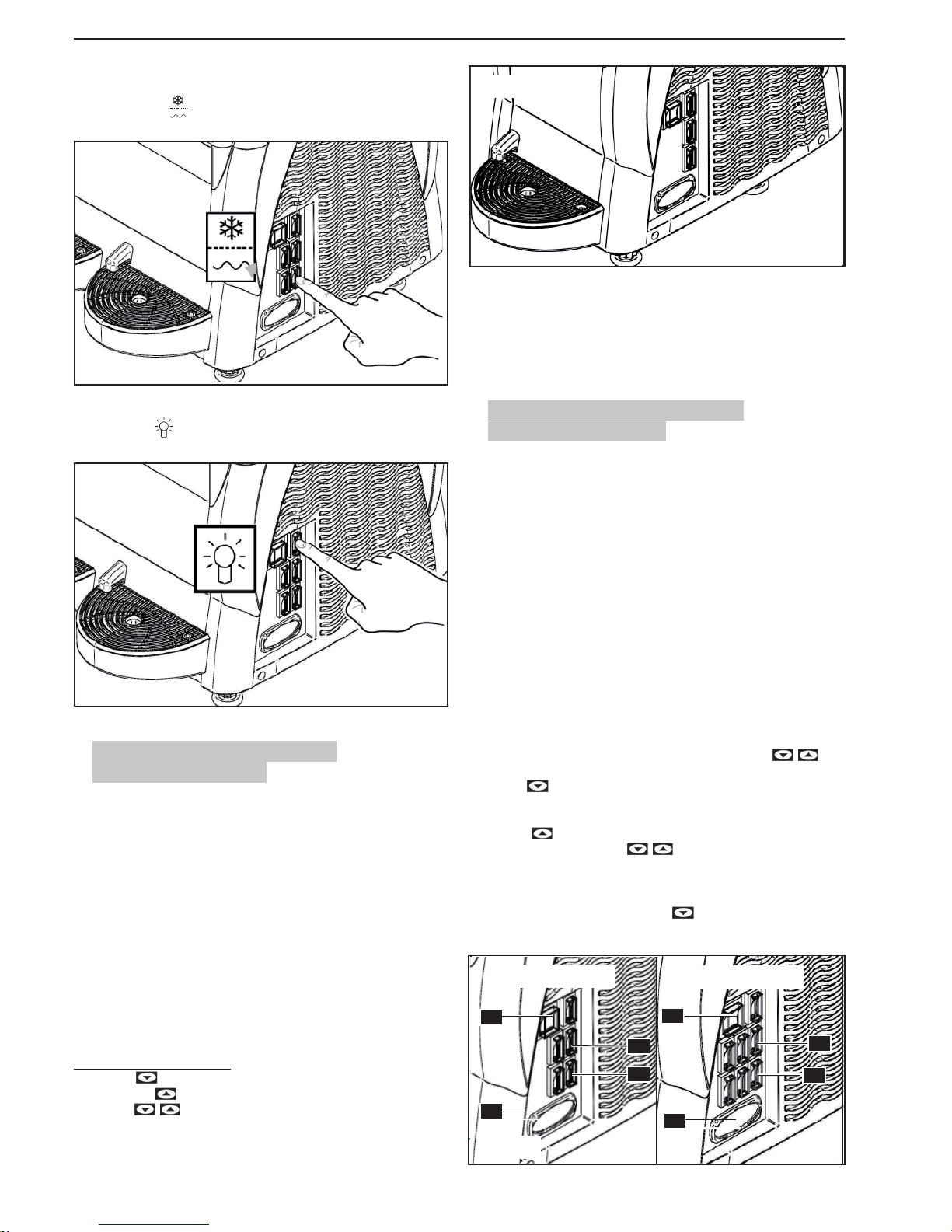
- 10 _EN- SL320005700 Ed.00 - 04-2011
To dispense COLD DRINKS:
Changeover switch : in position “II” refrigeration system on (cooling mode).
Press the switch
to turn on the machine lid light.
6.3. Starting the Granita maker 1
(Electronic thermostat)
The temperature display serves to view the temperature of the product inside
the tank and to regulate it when the machine is operating in “cold drinks fridge”
mode.
Switch (A) in position “I“: power is being supplied to the machine.
Switch (C) in position “I“: the mixer is operating.
To make SLUSH DRINKS (GRANITA):
Switch (D) in position “I“: Refrigerator system operating (slush drinks - granita).
To make COLD DRINKS:
Switch (D) in position “II“: Refrigerator system operating (cold drinks).
To disable the FRIDGE (mixing only):
Switch (D) in position “0“: Refrigerator system off (mixing only).
Setting the temperature set-point
- Press the . key; the display will read PrG.
- Press the key . the display will show the temperature set-point value.
-
Using the keys it is possible to change the set-point value from 0°C
- 10° C.
A
E
C
D
3 seconds after the last key is pressed, the setting is stored to memory and the
display will show the temperature of the product in the tank.
ALARMS
In case of probe failure, the display will read A1.
Programming and adjustment outputs will be disabled.
6.4. Starting the Granita Maker 2/3
(Electron ic thermostat)
For the sake of simplicity, we will show how to enable the right-hand tank; for
the other tanks, it is suffi cient to carry out the same sequence of operations on
the switches for the tank concerned.
Switch (A) in position “I“: Machine powered.
Switch (C) in position “I“: Mixers operating.
To make SLUSH DRINKS (GRANITA):
Deviators (D) in position “I“: Refrigerator system operating (slush drinks - granita).
To make COLD DRINKS:
Deviators (D) in position “II“: Refrigerator system operating (cold drinks).
To disable the FRIDGE (mixing only):
Deviators (D) in position “0“:Refrigerator system off (mixing only).
Setting the temperature set-point
- When the electronic thermostat is switched on, press the keys
together and the display will read “t1”.
- With the key it is possible to scroll through the set points “t1”; “t2” (Machine with 2 tanks) and, “t1”; “t2”; “t3” (Machine with 3 tanks).
- When the display shows the set point to be changed (“t1”or “t2” or “t3”),
press the key to view the set point value.
- It is then possible to use the keys to set the set-point value from
0°C - 10°C.
- The setting is stored to memory three seconds after the last key has been
pressed. The display returns to show “t1”or “t2” or “t3” according to the set
point that has been changed. Press the
key until the display shows the
temperature of the product in the tank.
ALARMAS
Fig.13
Fig.14
Fig.15
2 T ANKS
3 T ANKS
A
E
D
C
E
A
C
D
Fig.16
Page 73
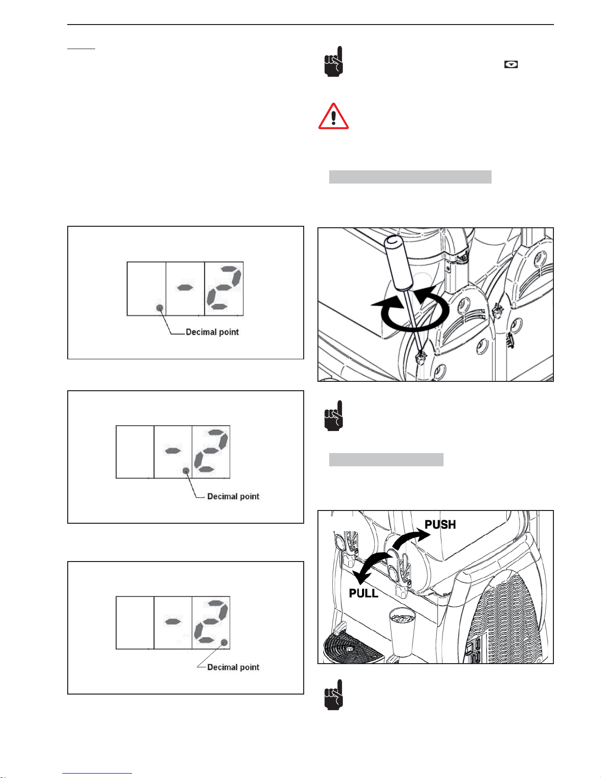
SL320005700 Ed.00 - 04-2011 - 11 _EN-
6.5. Adjusting granita consistency
The consistency of the granita may be adjusted (+/-) by means of the screw
shown in the fi gure +: thicker consistency, -: thinner consistency.
6.6. Dispensing granita
To dispense the beverage, pull the tap lever.
The adjustment may be made by hand or with the aid of a suitable fl at-tip screwdriver.
ALARMS
In case of probe failure, the display will show the following alarm messages:
“A1”: Tank 1 probe disconnected
“A2”: Tank 1 probe short circuit
“A3”: Tank 2 probe disconnected
“A4”: Tank 2 probe short circuit
“A5”: Tank 3 probe disconnected
“A6”: Tank 3 probe short circuit
During operation, the electronic thermostat shows the temperature of the product in the tanks, cyclically showing the temperature of the product fi rst in one
tank and then in the other, every 3 seconds.
To see which tank is referred to with the temperature reading, it is necessary to
check which decimal point is being shown.
If the decimal point viewed is on the left, the temperature reading refers to the
tank 1 (see Fig.2 Page 4).
If the decimal point viewed is in the centre, the temperature reading refers to the
tank 2 (see Fig.2, Page 4).
If the decimal point viewed is on the right, the temperature reading refers to the
tank 3 (see Fig.2, Page 4).
Fig.18
2 T ANKS
Fig.19
3 T ANKS
Fig.17
Note: If while using machine, the electronic thermostat should
switch off suddenly, to start it again press the . key. If the
electronic thermostat should not switch on again, switch off the
machine and contact your nearest assistance centre.
Important: While using the machine, the electronic thermostat
must always be on so as to show the temperature of the product
in the tanks.
Check the temperature of the product in the hopper on a regular
basis, using a sample thermometer to make sure that the product
remains always under the storage temperature. For machine models equipped with temperature display, also check that the temperature of the product, as measured by a sample thermometer,
corresponds to the temperature shown on the machine. If there
Fig.20
Fig.21
Page 74
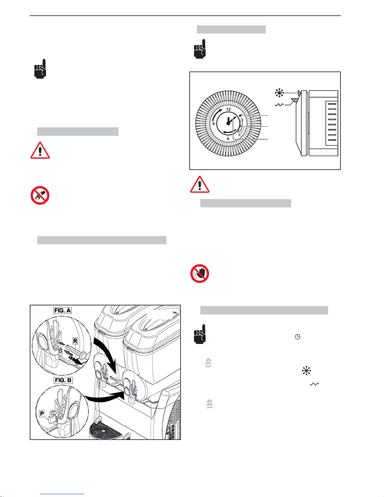
- 12 _EN- SL320005700 Ed.00 - 04-2011
6.9. Optionals (Timer)
The timer shown is given as an indication only.
A
B
C
Fig.23
The timer must be set while the main switch is positioned on
-0- and the machine is unplugged.
6.9.1. Setting the current time
Before you start using the timer you must set the current date and time.
To set, turn the timer dial in the direction indicated by the arrow until the indi-
cator (A) shows the correct date; then turn the pointer (C) until reaching the
current time
Do not:
• turn the pointer using a tool;
• turn the pointer in the direction opposite that shown in
the timer.
6.9.2. Operating the machine with the timer
In all machines equipped with a timer, the user must check that
the selector (B) is in the central position .
The machine must be started as shown in section 6.2.
Switch
in position “I”:
- to obtain granita position the timer lever in position
on the desired
date and time;
- to obtain cold drinks position the timer lever in position
on the de-
sired date and time.
Switch
in position “II”:
the timer is off and the machine works as a beverage cooler only.
is still product to be used up in the hopper, never disconnect the
machine from the mains power or switch off the machine; leave
the machine on in granita or refrigerated drinks mode.
If the machine is not used continuously, when used with milkbased products, it is necessary to:
- spray sanitizer solution around the spigot area and on the
spigot itself (alternatively, wash with a clean cloth and sanitizer);
or:
- Dispense a small amount of the product from the spigot before dispensing the serving for the customer.
6.7. Emergency situations
WARNING: in every emergency situation, to shut down the machine, fi rmly press the main switch into position -0-.
In case of freezing, switch off the machine and contact a service center or
specialized technician.
If a fi re breaks out, the area must be immediately cleared to
make way for trained personnel provided with suitable safety
equipment. Always use approved extinguishers, never use water or substances of dubious nature.
6.8. Accessory (Optional) (Locking System)
Use the new tap locking system as follows:
Fig. A: When using the machine, place the rod “R” as showed in the
picture.
Fig. B: To lock the handle, insert the rod “R” in its hole and place the
padlock as showed in the picture.
Fig.22
Page 75
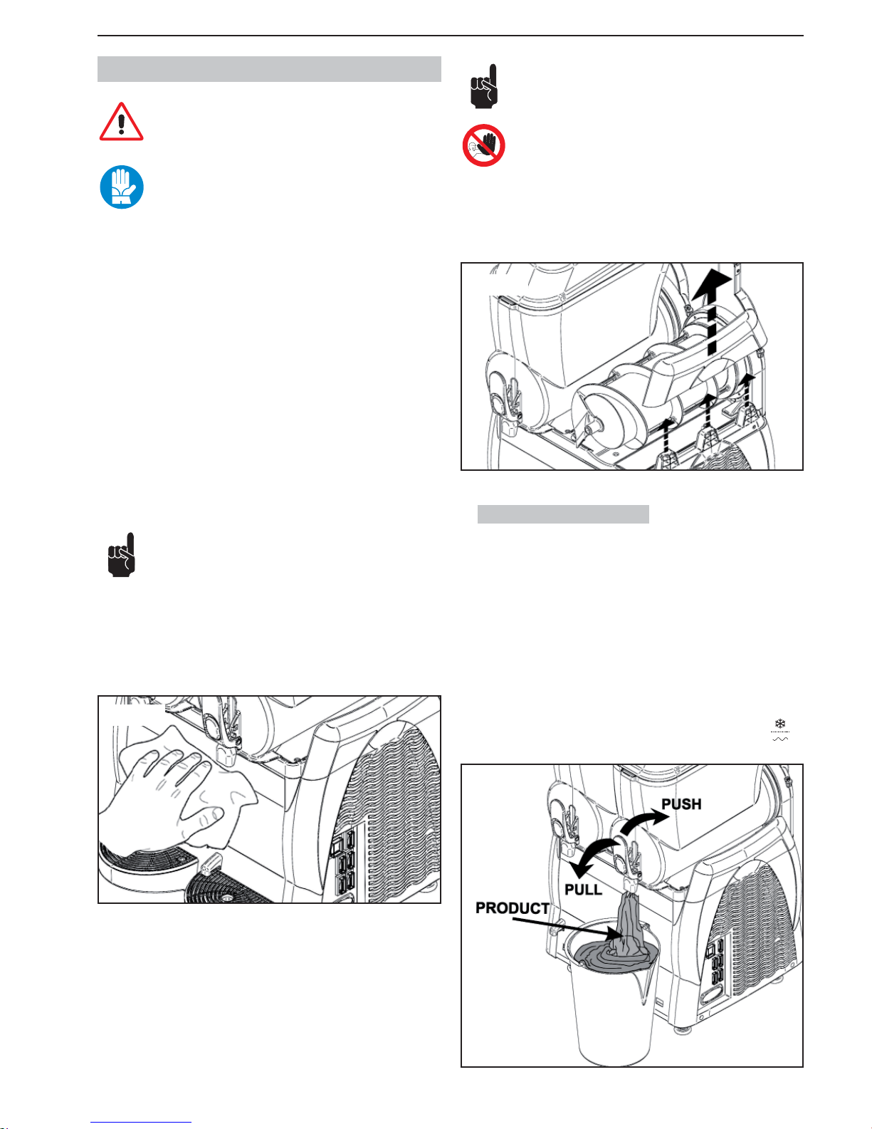
SL320005700 Ed.00 - 04-2011 - 13 _EN-
7. CLEANING AND MAINTENANCE
Before undertaking any cleaning and maintenance of external
machine components, make sure that the main switch is positioned on -0- and that the machine is unplugged.
Before performing any cleaning and maintenance operation on
the machine, wear the personal protections (gloves, glasses,
etc.), which are recommended by the safety standards in force
in the country where the machine is used.
When performing the Cleaning and Maintenance operations, follow these instructions:
• wear protection accident-proof gloves;
• do not use solvents or infl ammable materials;
• do not use abrasive and/or metal sponges to clean the machine and its components;
• take care to avoid dispersing liquids in the surrounding area;
• do not wash machine components in a dishwasher;
• do not dry parts of the machine in a conventional and/or microwave oven;
• do not immerse the machine in water;
• do not expose the machine to direct sprays of water;
• for cleaning use only lukewarm water and a suitable sanitizing agent (conforming to current regulations in the user’s country) that will not risk damaging machine components;
• on completing work, make sure that all protective covers and guards that
have been removed or opened are set back in place and properly secured.
Cleaning and sanitization are operations that must be performed with utmost
care and on a regular basis to guarantee the quality of the beverages dispensed
and compliance with mandatory hygiene standards.
The bowl must be cleaned and sanitized at least once a day and
in any case, in compliance with the current hygiene regulations
in the country of use. These operations need to be performed
more frequently if demanded by the characteristics of the product used; for
more details, contact the product supplier. If the machine is not used continuously throughout the day, wipe the dispensing tap area and the product
outlet pipe with a clean cloth and sanitizing fl uid, as illustrated in the fi gure
below.
The stainless materials, plastic and rubber used to manufacture
said parts, as well as their particular shape, make them easy to
clean but do not prevent the build-up of germs and mold in the
event of inadequate cleaning.
It is forbidden to clean or service the machine when it is plugged
in and the main switch is positioned on -1- .
To carry out maintenance and cleaning of the machine, it is possible to remove
the upper parts of the side protections, if necessary. Lift the upper part with
no hesitation to remove them. Once fi nished, fi t the part in the side protection
again.
7.1. Emptying the bowls
Before a bowl may be cleaned, it must be emptied of the previously prepared
product.
If the bowl is to be cleaned prior to the fi rst use of the machine, it need not
be emptied. In such a case refer directly to section 7.2.
For the sake of simplicity only the operation of the right bowl will be illustrated;
to operate the other bowls simply carry out the same sequence of steps on the
switches of the bowl in question.
The procedure shown below applies to models with and without electronic thermostat.
With the machine switched on, put the freeze/cool changeover switch
on
“O”, and empty the bowl of all its contents.
Fig.24
Fig.26
Fig.25
Page 76
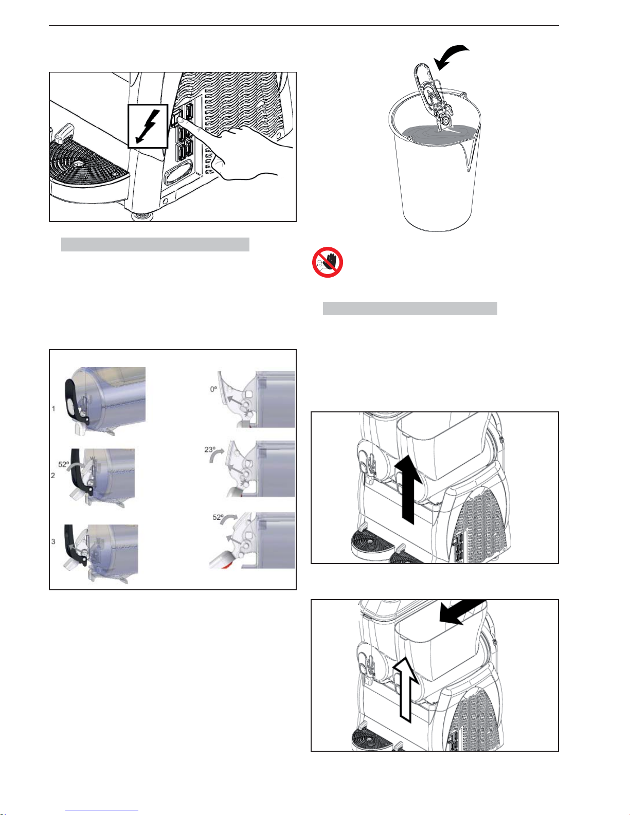
- 14 _EN- SL320005700 Ed.00 - 04-2011
Never disassemble the tap if the product or any other liquid is
present inside the bowl.
7.3. Removing the bowl and the lid
Removal of every machine bowl is fundamental to ensure correct machine
cleaning and sanitization.
To remove a bowl correctly proceed as follows:
1 remove the lid as shown at paragraph 6.1.
2 raise the front part of the bowl to release it;
After that, put off both the main switch and mixer switch and unplug the ma-
chine.
7.2. Disassembling the dispensing tap
Before removing the bowl it is recommended to disassemble the tap; after
cleaning the tap must not be reapplied until the bowl has been correctly positioned in its seat.
Disassemble the tap removing the pins from its seat to release all the other
parts. Push the “push lever dispenser until contact with the tank and pull upwards as shown in the fi gure:
These components may be placed in a basin containing hot water (approx.
50°C); Therefore it is possible to perform a carefully wash. as shown in section
7.4.
3 remove the bowl from its seat by pushing and tapping lightly on the rear
part;
4 take out the auger and remove the seals (A and B).
Fig.28
Fig.29
Fig.30
Fig.31
Fig.27
Page 77
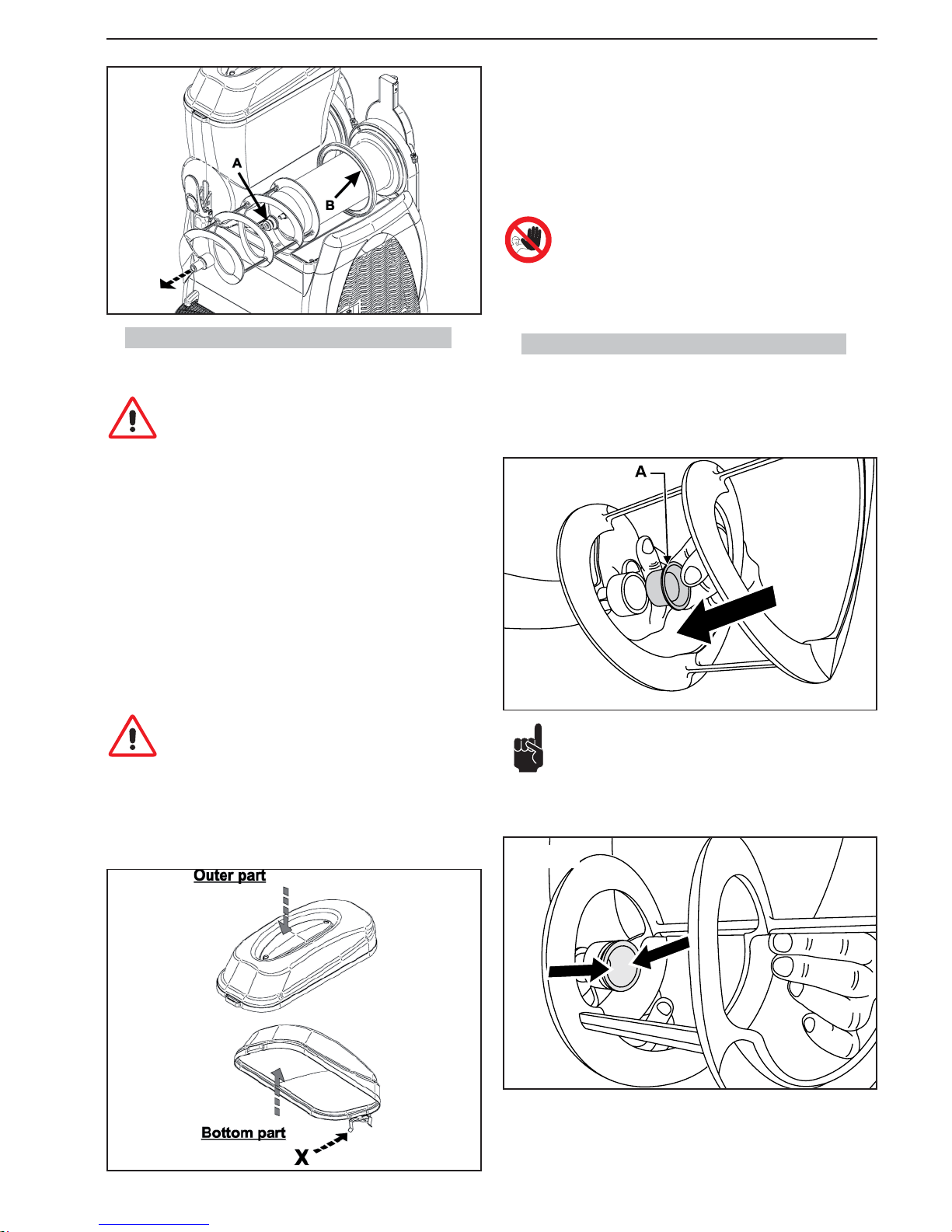
SL320005700 Ed.00 - 04-2011 - 15 _EN-
7.4. Washing and sanitizing the components
All of the previously disassembled and removed components must be thoroughly washed and sanitized.
Important: the sanitizing solution must comply with the regula-
tions in force at the time the machine is used.
To carry out the procedure correctly, please use the following instructions:
1 Fill a container with a sanitizer solution mixed in water (2% of sodium hy-
poclorite mixed in water)
2. Thoroughly wash the tank, lid and evaporator with a sponge soaked in the
sanitizer solution
3 Thoroughly wash again with clean water
4 Fill another container with a sanitizer solution
5 Dip the dismantled components into the sanitizer solution
6 Leave the dismantled components to soak in the solution for 30 minutes
7 Thoroughly wash again with clean water
8 Place the components on a clean surface and dry them
9 Assemble the machine as described in part 7.5
10 Before using the machine again carry out the rinsing cycle with clean water
( part 7.6 ).
Warning: do not submerge lids equipped with lighting in any
type of liquid. Before starting the cleaning and sanitising operations of the lid, remove it from the machine as described in the
previous chapter.
To clean the lighted lid correctly, proceed as follows;
1. Using a clean, damp cloth, fi rst wipe clean the bottom part of the lid (in con-
tact with the product);
2. Using a clean, damp cloth, wipe clean the whole outer part;
Fig.35
Fig.34
7.5. Reassembling the washed components.
All of the washed and sanitized components must be carefully reassembled.
Some components must be adequately lubricated in order to ensure that they
work effi ciently.
Apply the seal (A) on the auger as shown in the fi g.34.
Important Note: always check the seal integrity; should it be
worn, replace it with a new one.
Replace the seal (A) once a year at least.
Using the Vaseline provided, lubricate the seal (A) in the areas shown in the
fi g.35.
3. Using a sponge dipped in sanitising solution, sanitise the bottom part of the
lid, taking care not to wet the contacts (X);
4. Allow to act for 30 minutes;
5. Rinse twice or more, only the bottom part, with a clean sponge soaked in
fresh water.
6. Place the lid on a clean surface and dry it; fi rst dry the bottom and then the
outer part by means of a clean cloth.
7. Set the lid back in place only after having cleaned and sanitised the bowl.
It is forbidden to wash and/or sanitise the lid while it is installed
in the machine.
Fig.32
Fig.33
Page 78
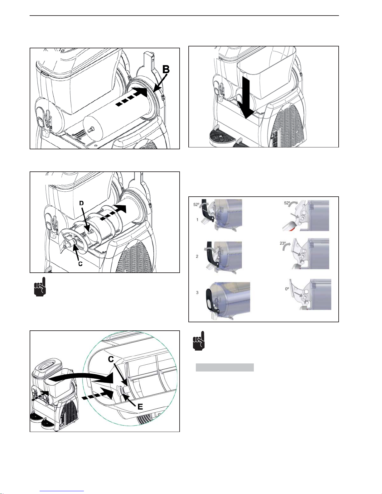
- 16 _EN- SL320005700 Ed.00 - 04-2011
Apply seal (B), lubricating the entire surface indicated by the arrows with Vaseline.
Introduce the auger, engaging head (C) with shaft (D).
Note: rotate the auger to engage it.
Set the bowl back in place; slightly raise head (C) of the auger so that it meets
the seat provided (E) in the bowl.
Follow these instructions to refi t the tap:
1 using the vaseline provided, adequately lubricate the joint
2 lean the pins on its seat and push the “push” lever dispenser until introduce
the tap.
Press the bowl downward until it engages the surface as shown in the fi gure.
Note: Correctly install the components as shown in the fi gure.
The non-lubrication of the cap may cause product leakage from
the tap.
7.6. Rinsing cycle
Before starting up the machine, you must carry out the rinsing cycle.
Proceed as follows:
1 fi ll the tank with clean water
2 let the machine on for 5 minutes in the “agitation” mode only
3 turn off the machine and empty the tank by opening the tap
Fig.36
Fig.37
Fig.38
Fig.39
Fig.40
Page 79
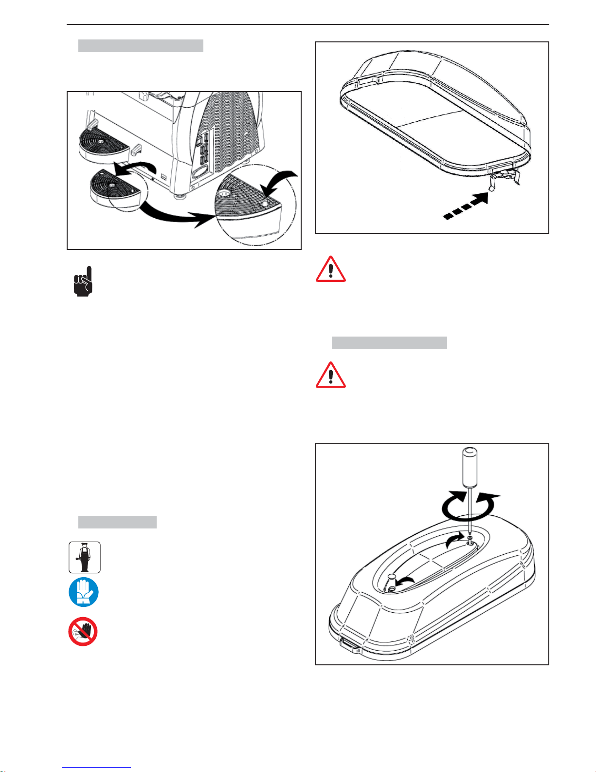
SL320005700 Ed.00 - 04-2011 - 17 _EN-
7.7. Cleaning the drip tray
The drip tray should be emptied and cleaned daily.
Note: all of the drip trays present in the machine should be
cleaned.
The drip tray should be emptied and cleaned every time the red
fl oat installed in the grid rises into view.
Holding the drainage hose fi rmly, lift the tray with the grid on top of it and pull
it out.
Wash the tray and grid separately with lukewarm water.
Dry all of the components.
Reposition the grid on top of the tray.
Position the drainage hose in the opening provided.
Fit the tray back in place and press down to secure it to the machine.
7.8. Lighted lid
Maintenance of the lighted lid must be entrusted solely to a
specialized technician, who must organize all of the operational sequences and use suitable equipment, in strict compliance
with the applicable regulations currently in force.
The operator is forbidden to disassemble any lid component.
Clean the lid contacts using a wet cloth, and dry carefully. Always
carry out this operation when the machine is off.
Remove the bulb “U” from the socket “T” , and replace it with a new one.
Refi t the lid, and tighten both screws.
7.8.1. Bulb replacement
The bulb must be replaced only when the main switch is in position -0- and power cord is unplugged.
remove the protection caps; undo both screws to split the lighted lid sections;
use a proper screwdriver for this operation.
Warning: during the cleaning operations, take care not to damage (bend, break, etc.) the contacts; any damage might cause a
bad functioning of the lid, which is not under warranty.
Fig.41
Fig.43
Fig.42
Page 80
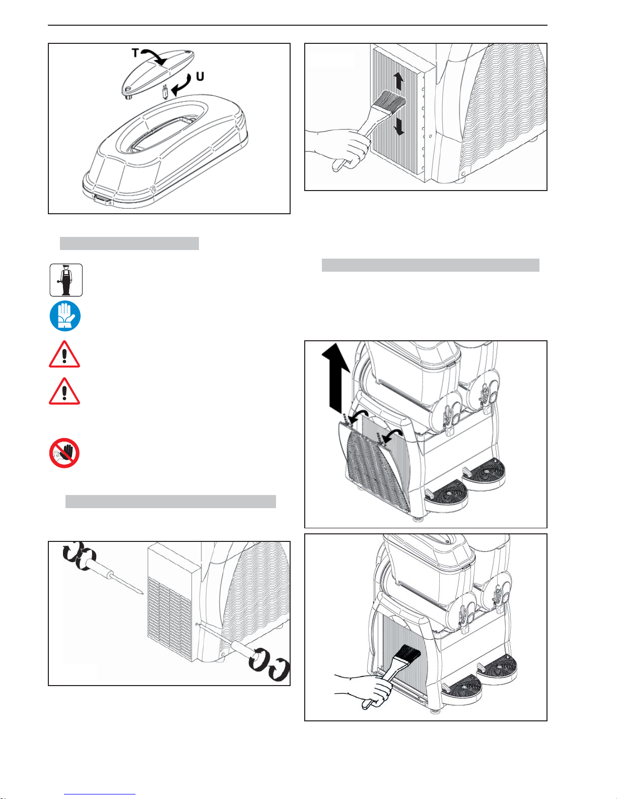
- 18 _EN- SL320005700 Ed.00 - 04-2011
7.9.1. Cleaning the Granitore 1/1FF condenser
The safety guards must be removed by means of a suitable screwdriver.
Remove the rear guard after taking out the screws securing it to the frame (the
screws are positioned on the left and right sides).
After removing the guard, use a dry brush to remove the dust that has built up
over time with use.
Fig.45
7.9. Cleaning the condenser
The condenser may be cleaned solely by a specialized technician, who must organize all of the operational sequences and
use suitable equipment, in strict compliance with the applicable regulations currently in force.
Periodically clean the condenser situated inside the machine.
Warning: Removing safety guards will expose some sharp surfaces of the machine.
A dirty condenser will impair machine performance.
To access the condenser remove the safety guards.
It is forbidden to use the machine when even only one panel
(front, rear or side) is not set properly in place. It is prohibited
for the operator to clean the condenser.
Once the condenser has been thoroughly cleaned, fi t all the safety guards back
in position.
Fig.46
After removing the guard, use a dry brush to remove the dust that has built up
over time with use.
7.9.2.
Cleaning Granitore 2/2 FF - 3/3 FF cond.
To remove the safety guard panel, proceed as follows:
- Lift and completely remove the upper part of the side guard;
- Unattach the fl aps pushing them simultaneously and pulling the panel as
shown in the fi gure;
Fig.44
Fig.47
Fig.48
Page 81
SL320005700 Ed.00 - 04-2011 - 19 _EN-
After having thoroughly cleaned the condenser, reassemble all the components.
7.10. Periodic maintenance
The machine must be periodically checked (at least once a
year) by a specialised technician.
This periodic check serves to ensure that all the components
installed and the machine itself are maintained at a high level
of safety.
Any worn components must be replaced by an original spare part.
It is forbidden to use the machine when even only one of its
components is faulty or worn. Users are forbidden to perform
periodic maintenance.
8. SCRAPPING
Electric and electronic equipment must be disposed of in accordance with European Directive 2002/96/EC.
Such equipment may not be disposed of as normal municipal solid
waste but must rather be separately collected to optimise recovery
and recycling of the materials used to manufacture them.
All products are marked with the crossed out wheeled bin
symbol as
a reminder of separate collection obligations.
Correct observance of all of the provisions for the disposal of end-of-life products will contribute to safeguarding the environment.
Page 82
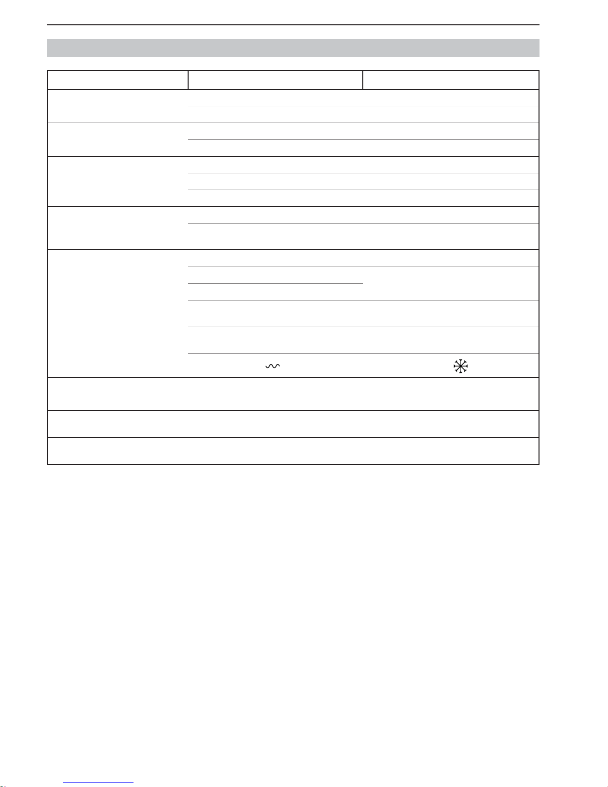
- 20 _EN- SL320005700 Ed.00 - 04-2011
9. TROUBLESHOOTING
Problem Cause Remedy
The machine does not turn on. The main switch is off (positioned on “O”). (Chap.6) Press the switch into position “I”.
The machine is not plugged in. Insert the plug in a suitable outlet.
The tap leaks. The tap plug is not lubricated. (Fig.38) Lubricate the plug.
The plug is defective. Replace the plug.
Product leaks from the rear part of the bowl. The bowl is not fi tted correctly in place . (Chap.7.5) Check the positioning of the bowl.
The bowl seal is not lubricated. (Fig.34) Lubricate accordingly.
The seal is defective. Replace the seal.
The auger does not turn The switch is positioned on “O”. (Chap.6) Press the switch into position “I”.
Blocks of ice inside the bowl. Switch off the machine, allow the bowl contents to melt
and check that the product has been correctly diluted.
The machine does not make granita. The switch is positioned on “O”. (Chap.6) Press the switch into position “I”.
The machine is near sources of heat. Install the machine in a suitable place.
There is insuffi cient ventilation.
The condenser is dirty. (Chap.7.9) Call in a specialized technician to clean the
condenser.
The consistency has not been adjusted correctly.
(Chap.6.4)
Correctly adjust the consistency.
Timer levers in position “
”. Place the levers in position “ ” see sect. 6.7
The auger is noisy. The front seal has been applied incorrectly. (Fig.32) Check that the seal is applied correctly.
The seal is not lubricated. (Fig.33) Lubricate the seal accordingly.
The tap does not dispense Blocks of ice inside the bowl. Switch off the machine, allow the bowl contents to melt
and check that the product has been correctly diluted.
If the machine malfunctions due to causes other than those listed in this table or the proposed remedies do not solve the problem, contact a specialized
technician.
Page 83
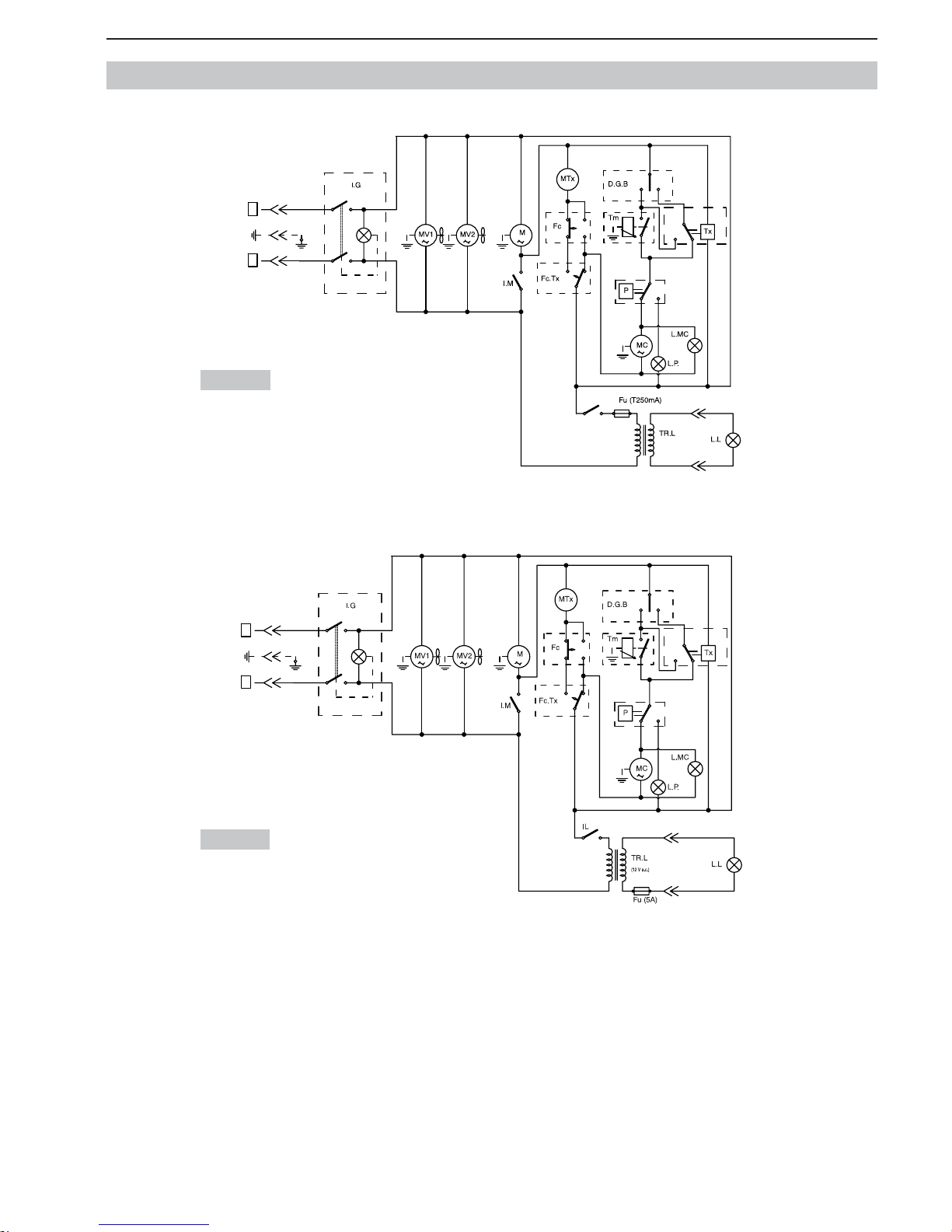
SL320005700 Ed.00 - 04-2011 - 21 _EN-
10. BASIC WIRING DIAGRAMS (GRANITORE 1 - 1 FF)
230 Volt
115 Volt
0
I
I
0
IL
0
I
0
I
I0II
t°
F
N
(12 V a.c.)
0
I
I
0
0
I
0
I
I0II
t°
F
N
Page 84
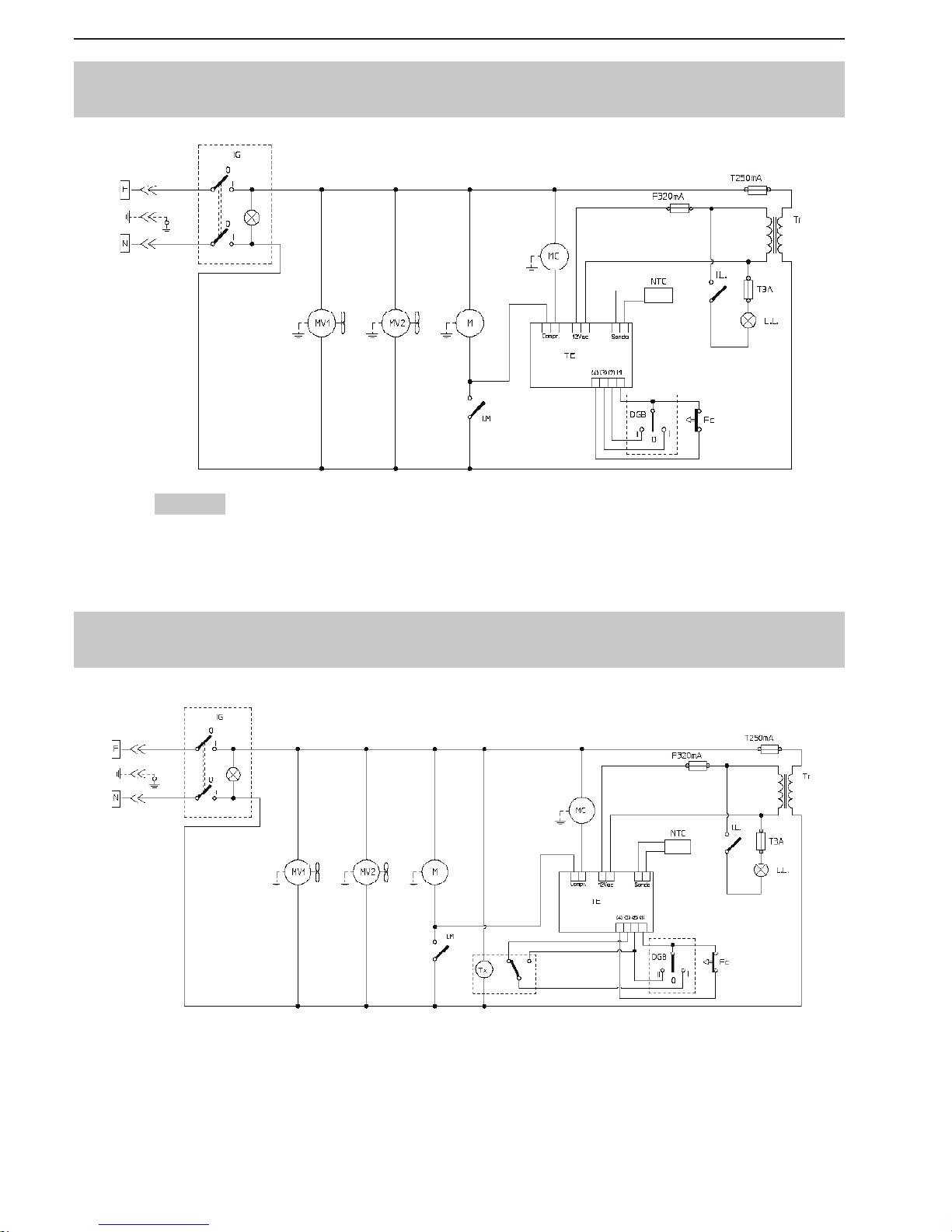
- 22 _EN- SL320005700 Ed.00 - 04-2011
BASIC WIRING DIAGRAMS
(GRANITA MAKER 1 - 1 FF WITH ELECTRONIC THERMOSTAT)
BASIC WIRING DIAGRAMS
(GRANITA MAKER 1 - 1 FF WITH ELECTRONIC THERMOSTAT +TIMER)
230 Volt
Page 85
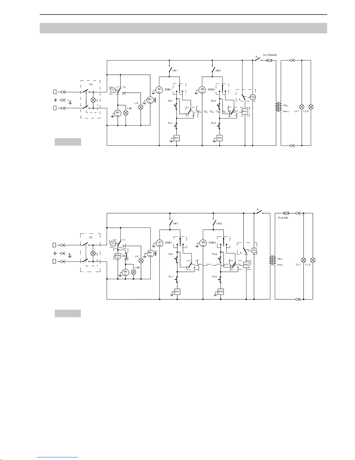
SL320005700 Ed.00 - 04-2011 - 23 _EN-
BASIC WIRING DIAGRAMS (GRANITORE 2 - 2FF)
230 Volt
115 Volt
IIIIII
I
0
0
I
0
I
I
0
F
N
IIIIII
I
0
0
I
0
I
I
0
F
N
Page 86
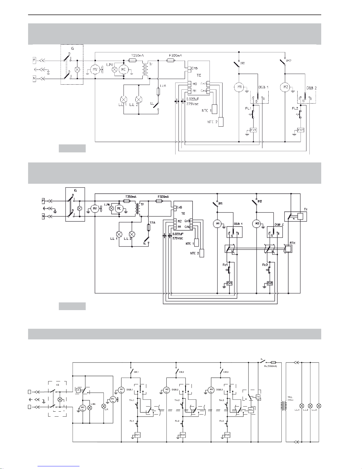
- 24 _EN- SL320005700 Ed.00 - 04-2011
BASIC WIRING DIAGRAMS (GRANITORE 3) / 230V
I
0
III IIIIII
I
0
0
I
0
I
I
0
F
N
BASIC WIRING DIAGRAMS
(GRANITA MAKER 2 - 2 FF WITH ELECTRONIC THERMOSTAT)
BASIC WIRING DIAGRAMS
(GRANITA MAKER 2 - 2 FF WITH ELECTRONIC THERMOSTAT +TIMER)
230 Volt
230 Volt
Page 87
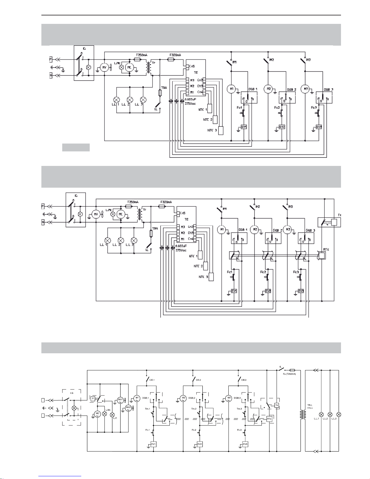
SL320005700 Ed.00 - 04-2011 - 25 _EN-
BASIC WIRING DIAGRAMS (GRANITORE 3FF) / 230V
I
0
III IIIIII
I
0
0
I
0
I
I
0
F
N
BASIC WIRING DIAGRAMS
(GRANITA MAKER 3 WITH ELECTRONIC THERMOSTAT)
BASIC WIRING DIAGRAMS
(GRANITA MAKER 3 WITH ELECTRONIC THERMOSTAT +TIMER)
230 Volt
Page 88
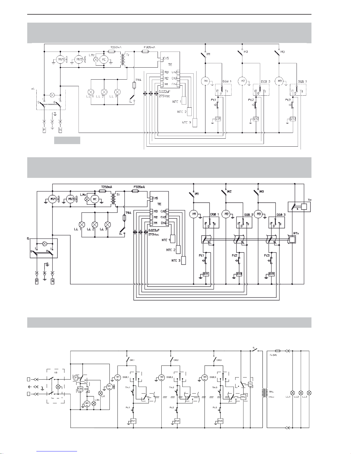
- 26 _EN- SL320005700 Ed.00 - 04-2011
BASIC WIRING DIAGRAMS (GRANITORE 3) / 115V
N
F
0
I
I
0
I
0
0
I
IIII IIII I
0
I
BASIC WIRING DIAGRAMS
(GRANITA MAKER 3 FF WITH ELECTRONIC THERMOSTAT)
BASIC WIRING DIAGRAMS
(GRANITA MAKER 3 FF WITH ELECTRONIC THERMOSTAT +TIMER)
230 Volt
Page 89
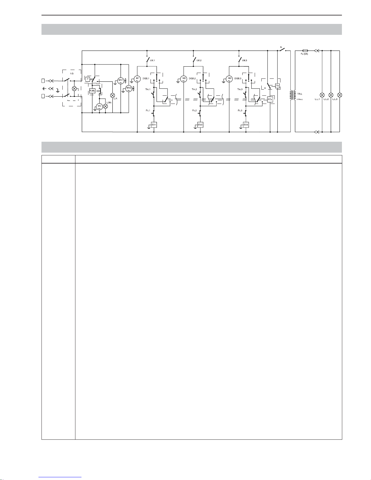
SL320005700 Ed.00 - 04-2011 - 27 _EN-
BASIC WIRING DIAGRAMS (GRANITORE 3FF) / 115V
I
0
III IIIIII
I
0
0
I
0
I
I
0
F
N
Item Description
D.G.B
DGB.1
DGB.2
DGB.3
EV1
EV2
EV3
Fc
Fc.Tx
Fc1
Fc2
Fc3
Fu
FuA
I.G
I.L
I.M
I.M1
I.M2
I.M3
L.L.
L.L.1
L.L.2
L.L.3
L.MC
L.P.
M
M1
M2
M3
MC
MTx
MV
MV1
MV2
N.T.C
N.T.C 1
N.T.C 2
N.T.C 3
P
R.Mc
RTx
TE
Tm
Tm1
Tm2
Tm3
TR
TR.L
Tx
SLUSH/DRINK SWITH
TANK 1 SLUSH/DRINK SWITH
TANK 2 SLUSH/DRINK SWITH
TANK 3 SLUSH/DRINK SWITH
TANK 1 SOLENOID VALVE
TANK 2 SOLENOID VALVE
TANK 3 SOLENOID VALVE
LIMIT SWITCH ADJUSTMENT
TIMER LIMIT SWITCH
TANK 1 LIMIT SWITCH ADJUSTMENT
TANK 2 LIMIT SWITCH ADJUSTMENT
TANK 3 LIMIT SWITCH ADJUSTMENT
FUSE
AUXILIARY FUSE
MAIN SWITCH
LIGHTED COVER SELECTOR
IMIXING MOTOR SWITCH
TANK 1 MIXING MOTOR SWITCH
TANK 2 MIXING MOTOR SWITCH
TANK 3 MIXING MOTOR SWITCH
LIGHTED COVER LAMP
TANK 1 LIGHTED COVER LAMP
TANK 2 LIGHTED COVER LAMP
TANK 3 LIGHTED COVER LAMP
COMPRESSOR INDICATOR LIGHT
PRESSURE GAUGE LAMP
MIXING MOTOR
TANK 1 MIXING MOTOR
TANK 2 MIXING MOTOR
TANK 3 MIXING MOTOR
COMPRESSOR MOTOR
TIMER MOTOR
FAN MOTOR
FAN MOTOR 1
FAN MOTOR 2
TANK TEMPERATURE PROBE
TANK TEMPERATURE PROBE 1
TANK TEMPERATURE PROBE 2
TANK TEMPERATURE PROBE 3
PRESSURE GAUGE
COMPRESSOR RELAY
TIMER RELAY
ELECTRONIC THERMOSTAT
TANK THERMOSTAT
TANK 1 THERMOSTAT
TANK 2 THERMOSTAT
TANK 3 THERMOSTAT
TRANSFORMER
TRANSFORMER
TIMER
LEGEND
Page 90

- 2 _DE- SL310005700 Ed.00 - 04-2011
INHALT
1. ALLGEMEINE INFORMATIONEN ...............3
1.1. Hersteller ..............................................................3
1.2. Zuständige Personen ...........................................3
1.3. Aufbau der Betriebsanleitung ...............................3
1.3.1. Zweck und Inhalt. ..........................................3
1.3.2. Zweckbestimmung. ........................................3
1.3.3. Aufbewahrung. ..............................................3
1.3.4. Symbole. ........................................................3
2. MASCHINENBESCHREIBUNG ..................4
2.1. Gebrauch der Maschine .......................................4
2.2. Hauptbestandteile ................................................4
2.3. Technische Angaben ............................................4
2.4. Beschreibung der Funktionen der Bedienertafel ..5
3. SICHERHEIT ...............................................6
3.1. Allgemeine Sicherheitsvorschriften ......................6
3.2. Abschaltfunktionen ..............................................6
3.3. Schilder ................................................................6
4. TRANSPORT UND LAGERUNG .................6
4.1. Verpackung ..........................................................6
4.2. Transport und Lagerung .......................................7
4.3. Lagerung ..............................................................7
5. INSTALLATION ...........................................7
5.1. Liste des mitgelieferten Zubehörs ........................7
5.2. Montage-Aufstellung ............................................7
5.3. Entsorgen der Verpackung ...................................8
5.4. Stromanschluss ....................................................8
6. BETRIEB .....................................................8
6.1. Zubereitung des Produkts ....................................8
6.2. Start Granitore ......................................................9
6.3. Start Granita-Maschine 1
(elektronischer Thermostat) ...............................10
6.4. Start Granita-Maschine 2/3
(elektronischer Thermostat) ...............................10
6.5. Einstellung der Festigkeit der Gramolate ...........11
6.6. Ausgabe von Gramolate ....................................11
6.7. Notsituationen ....................................................12
6.8. Verriegelungssystem zubehör
(Sonderausstattung) ...........................................12
6.9. Sonderzubehör (Zeitschaltuhr) ...........................12
6.9.1. Einstellung Uhrzeit .........................................12
6.9.2. Betrieb der Maschine mit Zeitschaltuhr ......12
7. REINIGUNG UND WARTUNG...................13
7.1. Leerung der Behälter .........................................13
7.2. Ausbau des Hahns .............................................14
7.3. Ausbau Behälter und Deckel ..............................14
7.4. Reinigung und Desinfektion der Teile .................15
7.5. Zusammenbau der gereinigten Teile ..................15
7.6. Spülzyklus ..........................................................16
7.7. Reinigung der Tropfschale .................................17
7.8. Leuchtdeckels ....................................................17
7.8.1. Lampenersetzung ..........................................17
7.9. Reinigung des Kondensators .............................18
7.9.1. Reinigung des Kond. Granitore 1/1FF ...........18
7.9.2. Reinigung des Kond. Granitore 2/2FF-3/3FF ....18
7.10. Turnusmäßige Wartung ......................................19
8. ABBAU ......................................................19
9.
PROBLEME-URSACHEN-MASSNAHMEN
..20
10. STROMLAUFPLÄNE.................................21
Page 91
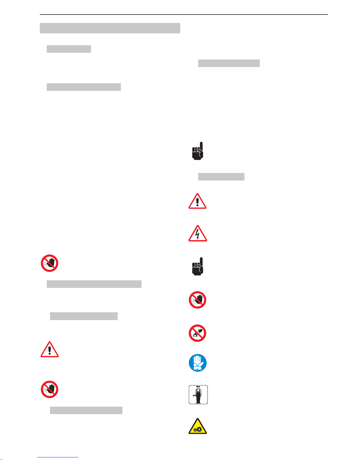
SL310005700 Ed.00 - 04-2011 - 3 _DE-
1. ALLGEMEINE INFORMATIONEN
1.1. Hersteller
Die Angaben zum Hersteller befi nden sich auf der ersten und/oder letzten
Seite des Handbuchs.
1.2. Zuständige Personen
Für den Umgang mit der Maschine sind zwei Personen mit verschiedenen
Funktionen vorgesehen:
Benutzer
Person mit geeigneten technischen Kenntnissen in der Zubereitung der Produkte zur Ausgabe von Gramolaten gemäß den einschlägigen Hygienevorschriften.
Nach dem Lesen dieser Anleitung sollte diese Person folgende Arbeiten korrekt
ausführen können:
• Füllen bzw. Wechseln des Verbrauchsprodukts;
• Ausgabe des Produkts;
• Reinigung und Desinfektion der Maschine.
Fachtechniker
Person, die genaue Kenntnisse über Installation, Gebrauch und Wartung des
Gramolate-Geräts besitzt und im Einzelnen folgende Anforderungen erfüllt:
• Fähigkeit zur Instandsetzung der Maschine bei größeren Betriebsstörungen
und fundierte Kenntnis der Betriebsanleitung und aller Sicherheitsinformationen,
• Verständnis des Inhalts der Betriebsanleitung und richtige Interpretation der
Zeichnungen und Pläne,
• Kenntnis der wichtigsten Vorschriften in Bezug auf Hygiene, Unfallverhütung, Technologie und Sicherheit,
• spezifi sche Erfahrungen in der Wartung von Gramolate-Geräten,
• korrektes Verhalten im Notfall und Kenntnis über die Beschaffung und die
korrekte Anwendung der persönlichen Schutzausrüstungen.
Die Maschine darf nicht von Personen benutzt werden, die diese Anforderungen nicht erfüllen.
1.3. Aufbau der Betriebsanleitung
Der Kunde muss die Informationen in diesem Handbuch aufmerksam durchlesen.
1.3.1. Zweck und Inhalt
Dieses Handbuch hat den Zweck, dem Kunden alle nötigen Informationen in Bezug auf Installation und Gebrauch des Gramolate-Geräts zu liefern.
Bevor irgendwelche Arbeiten mit bzw. an der Maschine ausgeführt werden, müssen Benutzer und Fachtechniker die Anweisungen in diesem Handbuch aufmerksam lesen.
Bestehen Zweifel über das richtige Verständnis der Anweisungen, sollte der
Hersteller kontaktiert werden.
Es sind keinerlei Arbeiten mit bzw. an der Maschine zulässig, wenn
dieses Handbuches nicht gelesen oder der Inhalt nicht verstanden wurde.
1.3.2. Zweckbestimmung
Dieses Handbuch ist an Benutzer und Fachtechniker gerichtet.
Benutzer dürfen die den Fachtechnikern vorbehaltenen Arbeiten nicht
ausführen.
Der Hersteller haftet nicht für Schäden, die wegen Missachtung dieses Verbots
entstanden sind.
Die Betriebsanleitung ist Bestandteil des gekauften Produkts und muss dieses
immer, auch im Falle eines Besitzerwechsels, begleiten.
1.3.3. Aufbewahrung
Die Betriebsanleitung in Maschinennähe aufbewahren.
Damit diese Betriebsanleitung auf Dauer vollständig und lesbar erhalten bleibt,
empfi ehlt es sich, folgende Hinweise zu beachten:
• Sorgfältig mit dem Handbuch umgehen, damit es unversehrt bleibt und auch
nicht teilweise beschädigt wird.
• Keine Teile des Handbuchs grundlos entfernen, herausreißen oder neu
schreiben.
• Das Handbuch vor Feuchtigkeit und Hitze geschützt aufbewahren, damit es
stets unversehrt und in all seinen Teilen leserlich bleibt.
Falls dieses Handbuch beschädigt wird oder verloren geht,
muss sofort ein neues Exemplar beim Hersteller oder beim
autorisierten Händler im Benutzungsland der Maschine angefordert werden.
1.3.4. Symbole
ALLGEMEINE GEFAHR
Gefahr, auch Lebensgefahr, für den Benutzer. In diesem Falls mit
größter Vorsicht vorgehen und V orkehrungen zum sicheren Arbeiten
treffen.
GEFÄHRLICHE ELEKTRISCHE SPANNUNG
Zeigt dem Personal an, dass beim beschriebenen Arbeitsgang die
Gefahr von Stromschlägen bei Missachtung der Sicherheitsvorschriften besteht.
HINWEIS
Hinweis oder Bemerkung zu Schlüsselfunktionen oder nützlichen
Informationen.
Den zu diesem Symbol gehörenden Texten ganz besondere Beachtung schenken.
VERBOT
Dieses Zeichen weist auf Handlungen hin, die absolut zu vermeiden
sind, weil sie eine Gefahr für den Benutzer und die Personen im
Umkreis darstellen.
BRÄNDE NICHT MIT WASSER LÖSCHEN
Dieses Zeichen bedeutet, dass es verboten ist, Brände mit Wasser
oder wasserhaltigen Produkten zu löschen.
PERSÖNLICHE SCHUTZAUSRÜSTUNG
Dieses Symbol bedeutet, dass eine persönliche Schutzausrüstung
getragen werden muss, da Unfallgefahr besteht.
FACHTECHNIKER
Weist auf Arbeitsgänge hin, die nur von qualifi zierten Fachleuten
ausgeführt werden dürfen.
BEWEGTE MASCHINENTEILE
Steht für die Gefahr durch die Teile der Maschine, die in Bewegung
sind. Die Maschine ausschalten, bevor irgendeine Tätigkeit daran
verrichtet wird.
Page 92
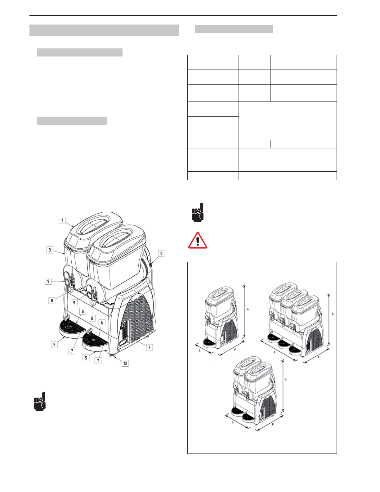
- 4 _DE- SL310005700 Ed.00 - 04-2011
2. MASCHINENBESCHREIBUNG
2.1. Gebrauch der Maschine
Die professionelle Maschine, die Sie gerade verwenden, ist geeignet für die
Herstellung von Granita und kalten Getränken. Sofern sie für Milchprodukte
verwendet wird und/oder die jeweiligen Gesetze dies für die verwendeten Produkte vorsieht, muss die Maschine mit der Option “Temperaturanzeige” für das
im Behälter befi ndliche Produkte ausgestattet werden. Darüber hinaus müssen
unbedingt die einschlägigen Vorschriften in Bezug auf die verwendeten Produkte eingehalten werden.
2.2. Hauptbestandteile
Die Hauptteile der Maschine sind:
1 Behälterdeckel
2 Dichteeinstellung
3 Behälter
4 Bedientafel
5 Tropfschale
6 Tropfgitter
7 Schwimmer “Tropfschale voll”
8 Produktausgabe
9 Hebel Produktausgabe
10 Füße
2.3. Technische Angaben
Im Folgenden eine Übersicht der technischen Daten und Merkmale.
Modell
Granitore 1
Granitore 1 FF
Granitore 2
Granitore 2 FF
Granitore 3
Granitore 3 FF
Abmessungen
L x P x A - (cm).
27 x 52 x 81 47 x 52 x 81 67 x 52 x 81
Gewicht (kg)
(leerer Behälter)
29
47 68
52 70
Max. Leistungsaufnahme (W)
Siehe Datenschild an der Seitenwand der
Maschine.
Betriebsspannung (V)
Betriebstemperatur Min. 20°C
Max. 32°C
Behälterzahl 1 2 3
Inhalt der einzelnen
Wasserbehälter (l).
12
Schallemission << 70 dB
A
Klasse. N
Zum einfacheren Verständnis der Anweisungen wurden in dieser Betriebsanleitung die folgenden Abkürzungen verwendet:
Granitore 1, Gramolate-Gerät mit (1) einem Behälter;
Granitore 2, Gramolate-Gerät mit (2) zwei Behältern;
Granitore 3, Gramolate-Gerät mit (3) drei Behältern;
Granitore 1 FF, Gramolate-Gerät mit (1) einem Behälter und Kühlanlage Fast Freeze;
Granitore 2 FF, Gramolate-Gerät mit (2) zwei Behältern und Kühlanlage Fast
Freeze;
Granitore 3 FF, Gramolate-Gerät mit (3) drei Behältern und Kühlanlage Fast
Freeze.
ANMERKUNG: Der Hersteller behält sich das Recht auf unangekündigte Änderungen an der Maschine vor.
Achtung! Änderungen und/oder Aufrüstungen mit Zubehörteilen
bedürfen der ausdrücklichen Genehmigung des Herstellers und
sind von diesem auszuführen.
Abb.1
Abb.2
Page 93
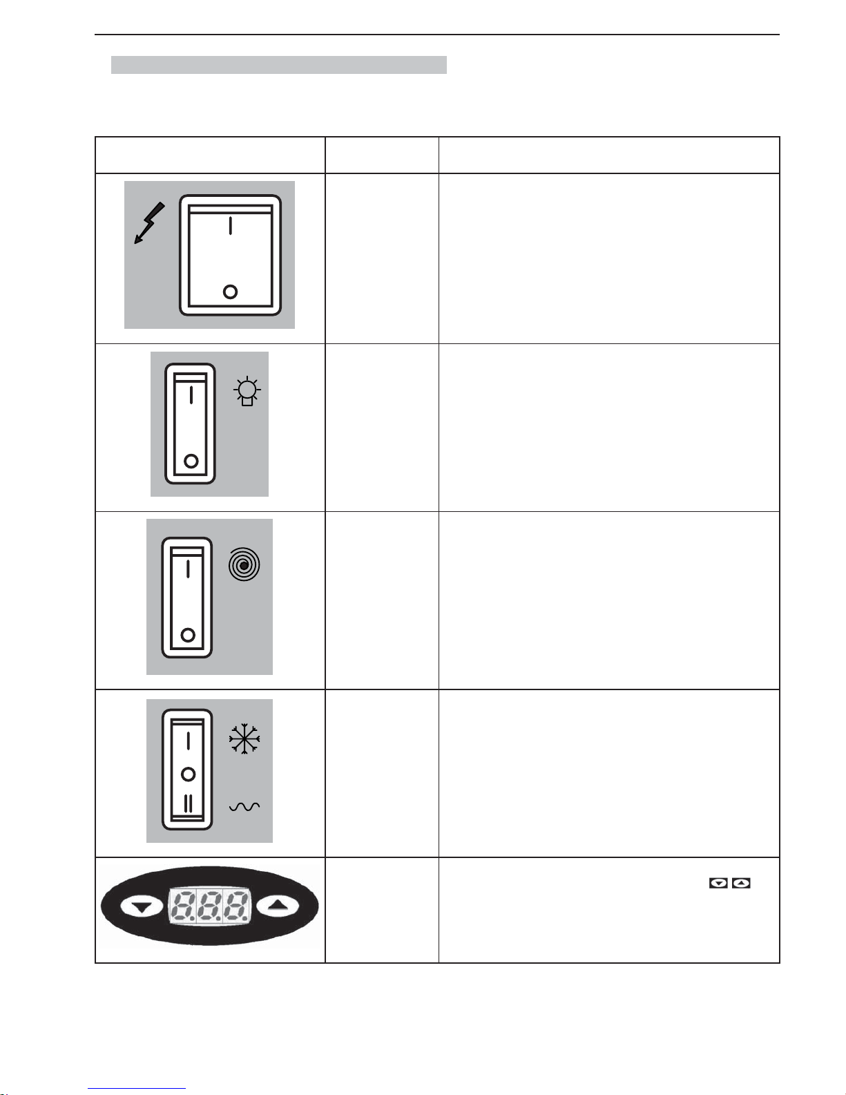
SL310005700 Ed.00 - 04-2011 - 5 _DE-
2.4. Beschreibung der Funktionen der Bedienertafel
Die Bedienelemente für die Maschine befi nden sich auf der seitlich angebrachten Bedientafel.
BEFEHL MODELL FUNKTION
ALLE
Hauptschalter: hat die Steuerfunktionen:
- Einschalten der Maschine;
- Ausschalten aller Funktionen der Maschine.
ALLE
Schalter Deckelbeleuchtung: schaltet die Beleuchtung (falls vorhanden) der
Behälterdeckel ein.
ALLE
Rührwerkschalter Behälter (einer für jeden Behälter): hat die Funktion des
Ein- und Ausschaltens des Getriebemotors, der die Rührschnecke des zugehörigen Behälters antreibt.
ALLE
Wechselschalter Kühlanlage (einer für jeden Behälter):
- in Stellung “0” ist die Kühlanlage ausgeschaltet;
- in Stellung “I” ist die Kühlanlage zur Herstellung von Gramolaten eingeschaltet;
- in Stellung “II” ist die Kühlanlage zur Herstellung von Kaltgetränken eingeschaltet.
FÜR ALLE VERSI-
ONEN MIT ELEKTRO-
NISCHEM THERMOS-
TAT
Elektronischer Thermostat:
- Zeigt die Temperatur im Behälter an. Anhand der Tasten
kann
die Getränketemperatur geändert werden, wenn die Maschine im “Kaltgetränke”- Betrieb arbeitet.
Page 94
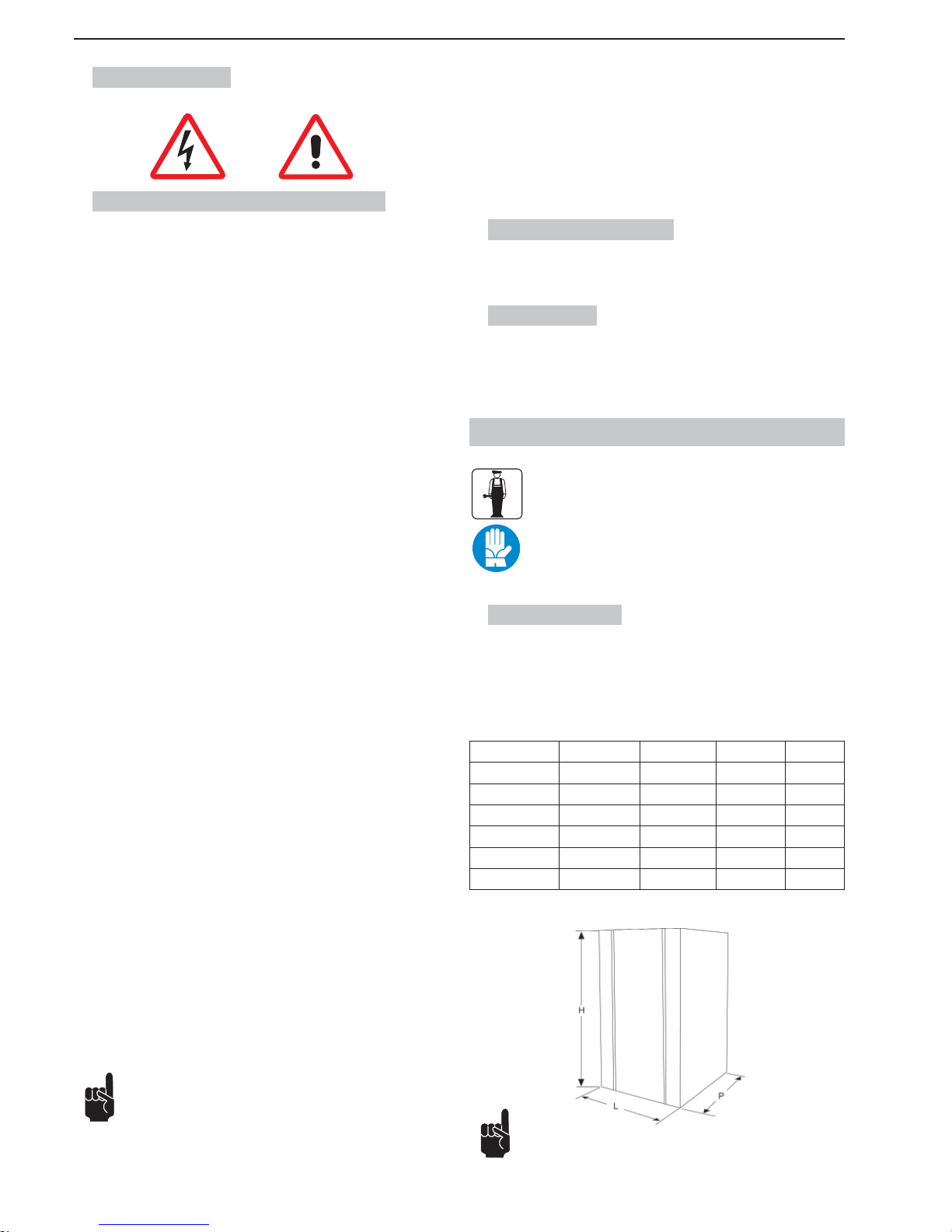
- 6 _DE- SL310005700 Ed.00 - 04-2011
3. SICHERHEIT
3.1. Allgemeine Sicherheitsvorschriften
• Die Betriebsanleitung vollständig durchlesen.
• Den Netzstromanschluss entsprechend den im Benutzerland geltenden Sicherheitsvorschriften ausführen.
• Die Steckdose für den Anschluss der Maschine muss
- für den Maschinenstecker geeignet sein,
- für die auf dem Schild an der Seitenwand der Maschine aufgeführten
Daten ausgelegt sein,
- an eine wirksame Erdungsanlage angeschlossen sein;
- an ein System mit Differentialschutz und Überlastschalter angeschlossen
werden.
• Das Netzkabel darf nicht
- mit Flüssigkeiten irgendwelcher Art in Berührung gelangen: Gefahr von
Bränden und/oder elektrischen Schlägen,
- gequetscht werden und/oder in Berührung mit scharfen Gegenständen
kommen,
- zum Ziehen der Maschine verwendet werden,
- weiterverwendet werden, wenn es beschädigt ist,
- mit feuchten oder nassen Händen berührt werden,
- während des Betriebs der Maschine zusammengewickelt werden.
- unerlaubt geändert werden.
• Es ist verboten,
- die Maschine anders als im Kap. 5 beschrieben zu installieren,
- die Maschine in Bereichen aufzustellen, wo eventuell mit Wasserstrahlen
gearbeitet wird,
- die Maschine in der Nähe von entzündlichen bzw. explosionsfähigen
Stoffen zu benutzen,
- Verpackungsteile, wie Plastiktüten, Polystyrol, Nägel für Kinder zugänglich aufzubewahren, da diese Gefahren bergen können,
- Kinder in der Nähe der Maschine spielen oder sich aufhalten zu lassen,
- nicht die vom Hersteller empfohlenen Ersatzteile zu verwenden,
- technische Änderungen an der Maschine vorzunehmen,
- die Maschine in irgendeine Flüssigkeit zu tauchen,
- die Maschine mit einem Wasserstrahl zu reinigen,
- die Maschine für andere Zwecke, als die in der Betriebsanleitung beschriebenen zu verwenden,
- die Maschine in schlechtem Gesundheitszustand, oder unter Einfl uss von
Drogen, Alkohol, Medikamenten usw. zu benutzen,
- die Maschine auf anderen Maschinen zu installieren,
- die Maschine in explosionsfähiger und aggressiver Atmosphäre oder bei hoher Konzentration von Staub und ölhaltigen Schwebestoffen zu benutzen,
- die Maschine in feuergefährdeter Umgebung zu benutzen,
- die Maschine zur Ausgabe von Stoffen zu verwenden, für die sie nicht
geeignet ist.
• Bevor der die Maschine gereinigt wird, kontrollieren, ob der Netzstecker
gezogen ist. Die Maschine darf nie mit Benzin und/oder Lösemitteln gleich
welcher Art gereinigt werden.
• Instandsetzungsarbeiten gleich welcher Art müssen von einer autorisierten
Servicestelle des Herstellers und/oder von geschulten Fachleuten ausgeführt werden.
• Die Gitter an den Maschinenseiten dürfen nicht abgedeckt werden.
• Die Maschine darf nicht in der Nähe von Heizungsanlagen (wie Öfen oder
Heizkörper) aufgestellt werden.
• Im Brandfall Kohlensäurelöscher (CO
2
) benutzen. Kein Wasser oder Lösch-
pulver verwenden.
Bei unsachgemäßem Gebrauch erlischt jede Form der Gewährleistung und der Hersteller lehnt jegliche Haftung für Personenund/oder Sachschäden ab.
Als unsachgemäß wird betrachtet:
- jeder andere Gebrauch als der vorgesehene und/oder mit anderen Methoden,
als die in dieser Anleitung vorgesehenen.
- alle Arbeiten mit bzw. an der Maschine, die im Gegensatz zu den Angaben in
dieser Anleitung stehen.
- jeder Gebrauch nach unerlaubten Änderungen an Maschinenteilen und/oder
Verstellungen der Sicherheitssysteme.
- jeder Gebrauch nach Reparaturen mit nicht vom Hersteller zugelassenen Ersatzteilen;
- die Installation der Maschine im Freien.
3.2. Abschaltfunktionen
Die Abschaltfunktionen der Maschine erfolgen über den Ein-/Ausschalter.
3.3. Schilder
KEINES DER SCHILDER AN DER MASCHINE DARF ENTFERNT, ABGEDECKT ODER BESCHÄDIGT WERDEN. DIES GILT INSBESONDERE FÜR
DIE SCHILDER MIT SICHERHEITSFUNKTION.
4. TRANSPORT UND LAGERUNG
Für alle in Kapitel 4 beschriebenen Arbeitsgänge ist ausschließlich
Fachpersonal zugelassen, das auch auf das Heben und Transportieren von verpackten und unverpackten Maschinen spezialisiert ist.
Es muss alle Arbeitsabläufe und den Einsatz von entsprechenden
Mitteln je nach den Merkmalen und dem Gewicht des Transportguts und unter strikter Einhaltung der geltenden einschlägigen
Vorschriften vorbereiten.
4.1. Verpackung
Die Maschine wird betriebsbereit in einer Kartonschachtel versandt. Die Kartonschachtel besteht aus Schachtelgehäuse und Deckel, die mit zwei Nylonbändern zusammengehalten werden.
ABMESSUNGEN UND GEWICHT DER VERPACKUNG
Breite (L) Tiefe (P) Höhe (H) Gewicht
Granitore 1 340 mm 540 mm 930 mm 32 kg
Granitore 1 FF 340 mm 540 mm 930 mm 32 kg
Granitore 2 560 mm 540 mm 930 mm 52 kg
Granitore 2 FF 560 mm 540 mm 930 mm 57 kg
Granitore 3 770 mm 540 mm 930 mm 72 kg
Granitore 3 FF 770 mm 540 mm 930 mm 74 kg
Anmerkung: Die Abmessungen und das Gewicht sind unverbindliche Angaben.
Abb.3
Page 95
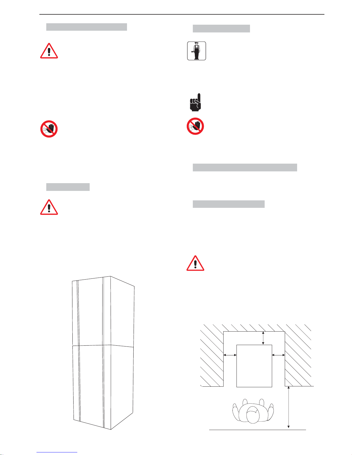
SL310005700 Ed.00 - 04-2011 - 7 _DE-
4.2. Transport und Lagerung
Sicherstellen, dass sich beim Heben und Handhaben der Last
niemand im Aktionsbereich aufhält. Unter schwierigen Bedingungen Personal für die Überwachung der auszuführenden Bewegungen bereitstellen.
Wird die Maschine von Hand bewegt, sind dafür mindestens zwei Personen nötig.
Die Maschine muss in senkrechter Lage transportiert werden und erst,
nachdem jeder Behälter entleert wurde.
Die verpackte Maschine anheben und vorsichtig transportieren. Unebene
Transportwege vermeiden und auf den Platzbedarf bzw. auf hervorstehende
T eile Acht geben.
Achtung: Die Verpackung nur einschneiden, wo es vorgesehen
ist.
Beschädigungen an der Maschine durch den Transport und die Handhabung sind nicht durch die GARANTIE gedeckt.
Reparaturen oder Erneuerungen beschädigter Teile gehen zu Lasten des
Kunden.
4.3. Lagerung
Bevor die Maschine gelagert wird bzw. wenn sie nach einer langen Lagerzeit in Betrieb gesetzt wird, gründlich reinigen und
desinfi zieren.
Achtung: Bei der Lagerung nicht mehr als zwei Maschinen aufeinander
stapeln.
Bei längerer Stillsetzung der Maschine sind folgende Vorkehrungen in Bezug
auf Ort und Dauer der Lagerung zu treffen:
• In einem geschlossenen Raum lagern.
• Vor Schlägen und Belastungen schützen.
• Vor Feuchtigkeit und großen Temperaturschwankungen schützen.
• Vor Korrosion schützen.
MAX
MAX
Abb.4
5. INSTALLATION
Für alle in Kapitel 5 beschriebenen Arbeitsgänge ist ausschließlich Fachpersonal zugelassen, das alle Arbeitsläufe
und den Einsatz von entsprechenden Mitteln zum Arbeiten
unter strikter Einhaltung der einschlägigen Vorschriften vor-
bereiten muss.
Die Maschine muss in einem beleuchteten und belüfteten Raum mit stabilem
und ebenem Boden installiert werden (Neigung < 2°).
Die Maschine bedarf der Überwachung und muss deshalb an
Stellen installiert werden, wo sie vom zuständigen Personal im
Auge behalten werden kann.
Achtung: Es ist verboten, die Maschine an Orten aufzustellen,
wo sie von anderen Personen als den in Paragraf 1.2 bezeichneten erreicht, berührt bzw. betätigt werden kann.
Die Temperatur des Raums, in dem die Maschine aufgestellt wird, sollte zwischen 20°C und 32°C liegen.
5.1. Liste des mitgelieferten Zubehörs
• Vaseline: zum Schmieren aller in diesem Handbuch angegebenen Teile
nach der Reinigung und Desinfektion.
5.2. Montage-Aufstellung
Der Bediener muss überprüfen, ob
• der Raum für die Installation der Maschine vorbereitet ist,
• die Fläche, auf die die Maschine gestellt wird, eben und stabil ist,
• der Raum ausreichend beleuchtet, belüftet und hygienisch sauber ist und die
Steckdose leicht erreichbar ist.
Um die Maschine herum muss genügend freier Raum gelassen
werden, damit das Personal ungehinderten Zugang zur Maschine hat und den Ort bei Bedarf auch unverzüglich verlassen
kann.
In Abbildung 5 sind die Mindestabstände für die Installation ersichtlich.
150 cm
60 inches
25 cm
10 inches
25 cm
10 inches
25 cm
10 inches
Abb.5
Page 96
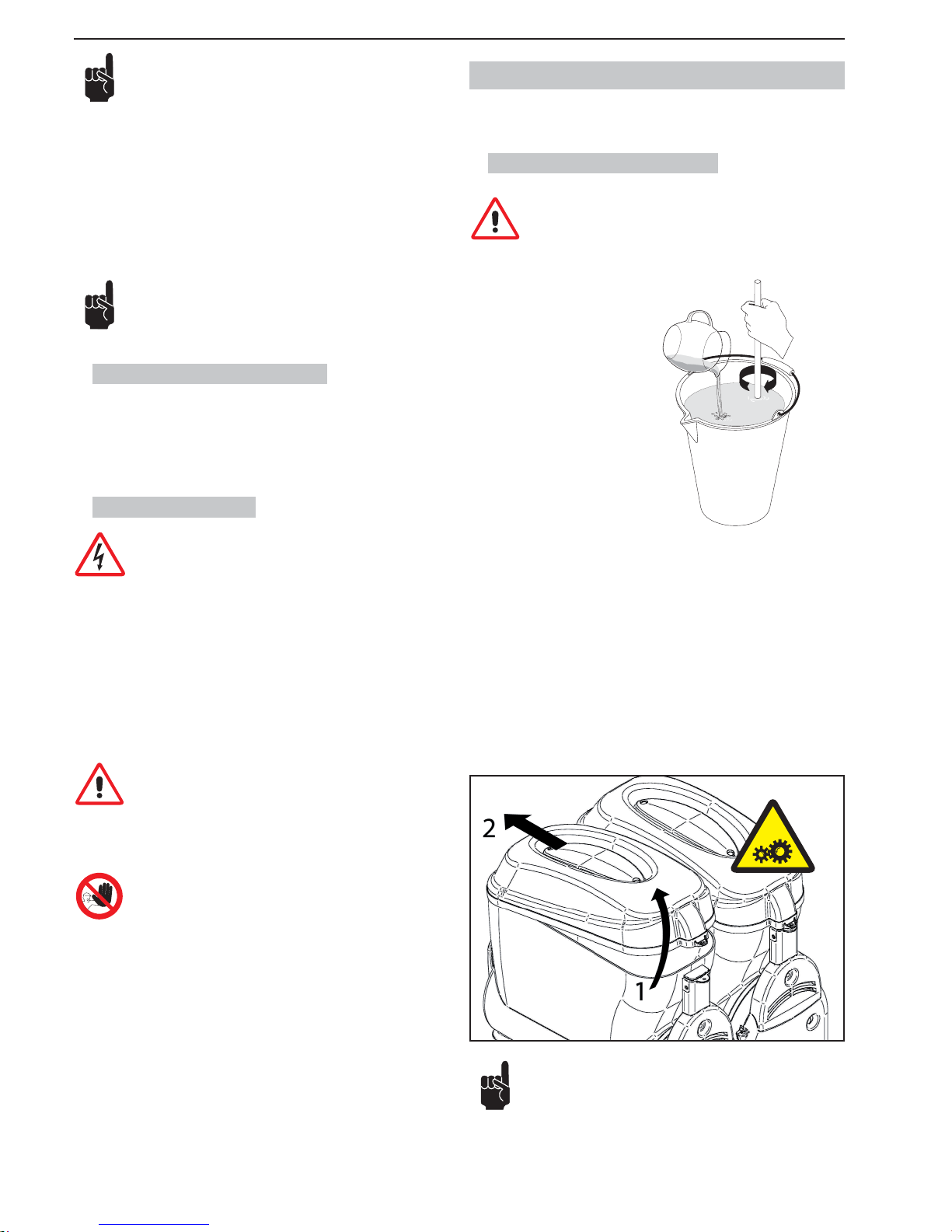
- 8 _DE- SL310005700 Ed.00 - 04-2011
WASSER
Hinweis: Im oberen Teil müssen 25 cm (10 Zoll) frei gelassen
werden.
In Abb. 5 ist der Platzbedarf für den Zugang angegeben:
• zur Bedientafel auf der rechten Seite;
• zu den Baugruppen im Fall von Störungen der Maschine.
Nach dem Abstellen der verpackten Maschine in der Nähe des Bestimmungs-
orts wie folgt vorgehen:
1. die Verschlussbänder der Verpackung durchschneiden;
2. die Kartonverpackung abheben;
3. dann die Maschine am vorbereiteten Ort aufstellen.
Bevor die Maschine zum ersten Mal in Betrieb gesetzt wird, ist eine
gründliche Reinigung der Bestandteile sowie eine Desinfektion der
Teile, die in Berührung mit dem Produkt kommen, erforderlich; für
weitere Einzelheiten, siehe das betreffende Kapitel.
5.3. Entsorgen der Verpackung
Beim Öffnen der Verpackung empfi ehlt es sich, die Verpackungsmaterialien zu
trennen und sie gemäß den Vorschriften im Benutzungsland zu entsorgen.
Die Verpackung für einen späteren Gebrauch aufbewahren.
5.4. Stromanschluss
Dieser Arbeitsgang darf nur von Fachkräften durchgeführt werden.
Bevor der Netzstecker in die Steckdose eingesteckt wird, sicherstellen, dass
der Ein-/Ausschalter auf „0“ steht.
Der Stromanschluss der Maschine erfolgt durch den Kunden und auf dessen
Verantwortung.
Die Maschine muss mit dem am Stromkabel montierten Stecker an das Stromnetz angeschlossen werden. Dabei sind zu beachten:
• die örtlichen Vorschriften und technischen Bestimmungen zum Zeitpunkt der
Installation,
• die technischen Daten auf dem Schild an der Seitenwand der Maschine.
Achtung: Die Steckdose für den Stromanschluss muss problemlos vom Benutzer erreichbar sein, damit die Maschine bei
Bedarf leicht vom Stromnetz getrennt werden kann.
Ist das Netzkabel beschädigt, sollte man sich zur Erneuerung nur an den
Hersteller oder eine Fachkraft wenden.
Es ist verboten:
• Verlängerungskabel, gleich welcher Art, zu benutzen;
• den Originalstecker auszutauschen;
• Adapter zu verwenden.
6. BETRIEB
Vor der ersten Inbetriebnahme ist die korrekte Installation der Maschine
durch einen Fachtechniker zu prüfen.
6.1 Zubereitung des Produkts
Achtung: Das Produkt kann erst in den Behälter geschüttet werden, wenn die Maschine stillsteht und der Netzstecker gezogen
ist.
Abb.6
In einem Gefäß das Konzentrat mit Wasser gemäß Herstellervorschriften verdünnen und mischen. DIE ERZEUGTE MISCHUNG MUSS EINEN MINDESTGEHALT AN ZUCKER VON 13% HABEN. Eine geringere Konzentration kann
die Rührschnecke und/oder den Getriebemotor beschädigen.
NIEMALS NUR WASSER BENUTZEN
Zum Abnehmen des Deckels vom Behälter wie folgt vorgehen:
1 den Deckel an der Rückseite anheben;
2 den Deckel aus der Feststelleinrichtung an der Vorderseite ziehen.
Achtung: Keine Gewalt anwenden, wenn sich der Deckel schwer
abnehmen lässt.
Abb.7
Page 97
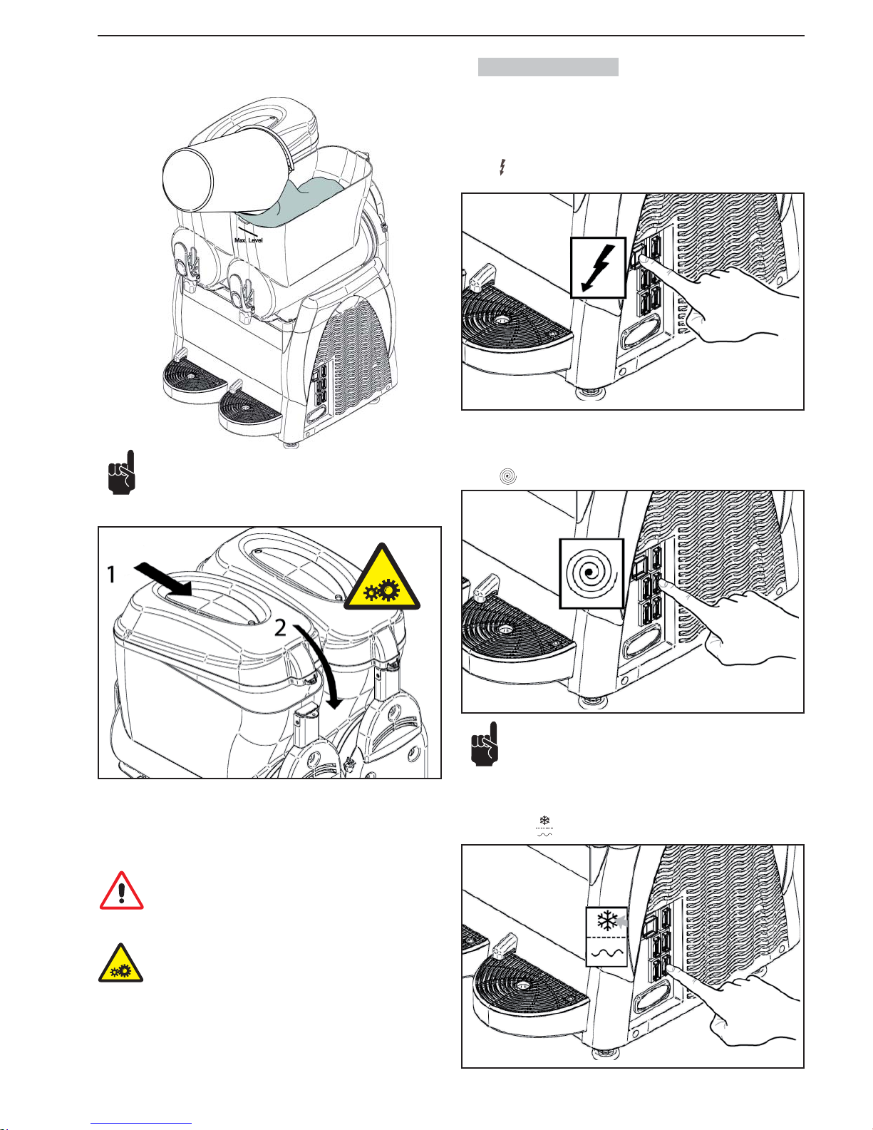
SL310005700 Ed.00 - 04-2011 - 9 _DE-
Beim Eingießen des Produkts in den Behälter muss man darauf achten, dass es das Produkt den maximalen Füllstand nicht
übersteigt.
KEINE WARME FLÜSSIGKEIT EINGIESSEN
(mit einer Temperatur von mehr als 25°C)
Nachdem das Produkt im Behälter gegossen zu haben, schließen mit dem Deckel.
Achtung : Einschalten das Gerät nicht, wenn der Deckel nicht
auf dem Behälter ist. Bevor der Deckel aufnehmen, schalten
das Gerät aus, und trennen die Steckdose ab.
Achtung: Im Inneren des Behälters befi nden sich bewegliche
Organe, die Verletzungen verursachen können; vor Eingriffen
in das Innere des Behälters die Maschine ausschalten und den
Stecker abziehen.
6.2. Start Granitore
Der Einfachheit halber wird nur gezeigt, wie der rechte Behälter zu betätigen
ist; für die Bedienung der anderen Behälter braucht nur dieselbe Schrittfolge an
den Schaltern des betreffenden Behälters ausgeführt zu werden.
Schalter
in Stellung “I”: An der Maschine liegt Spannung an.
Jeder Behälter wird von einem Schalter und einem Wechselschalter gesteuert,
die wie folgt zu betätigen sind:
Schalter
in Stellung “I”: Rührwerk in Betrieb.
Falls die Maschine eine Zeitschaltuhr besitzt, für die richtige
Einstellung in Paragraf 6.7 nachsehen.
Für eine GRAMOLATE
Wechselschalter : in Pos. “I” Kühlanlage in Betrieb (Eis)
Abb.8
Abb.9
Abb.10
Abb.11
Abb.12
Page 98
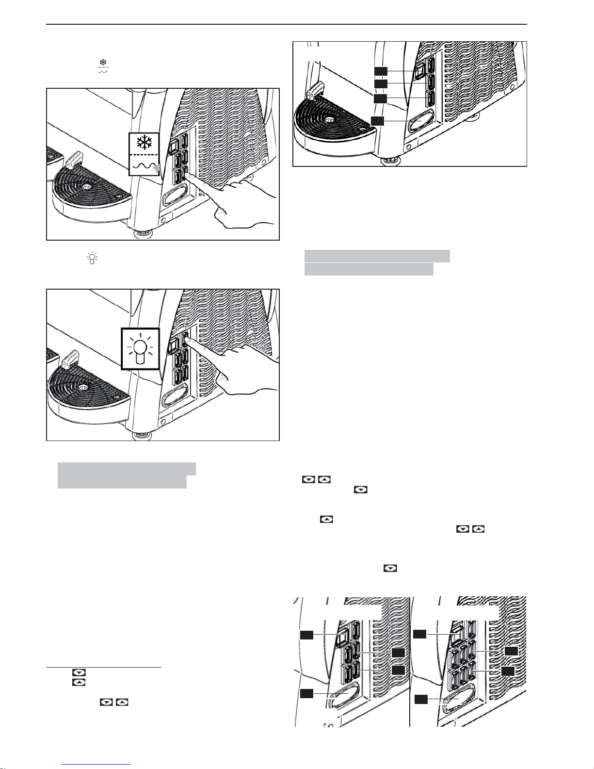
- 10 _DE- SL310005700 Ed.00 - 04-2011
Für ein KALTGETRÄNK
Wechselschalter
: in Pos. “II” Kühlanlage in Betrieb (Getränk).
Den Schalter
für die Deckelbeleuchtung drücken, um den Leuchtkörper an
der Maschine einzuschalten.
6.3. Start Granita-Maschine 1
(elektronischer Thermostat)
Die Temperaturanzeige hat die Aufgabe, die Temperatur des Produkts im Behälter anzuzeigen und diese zu regeln, wenn die Maschine in der Funktion “Getränkekühlung” arbeitet.
Schalter (A) in Stellung “I“: Maschine wird mit Spannung versorgt.
Schalter (C) in Stellung “I“: Mischer in Betrieb.
Zur Herstellung einer GRANITA:
Schalter (D) in Stellung “I“: Kühlanlage in Betrieb (Granita).
Zur Herstellung eines KALTGETRÄNKS:
Schalter (D) in Stellung “II“: Kühlanlage in Betrieb (Getränk).
Zum Abschalten der KÜHLUNG (nur Rühren):
Schalter (D) in Stellung “0“: Kühlanlage abgeschaltet (nur Rühren).
Einstellung des Temperatur - Setpoints
- Taste
betätigen: Das Display zeigt PrG an.
- Taste
betätigen: Das Display zeigt den Wert des Temperatur-Setpoints
an
-
Mit den Tasten kann der Setpoint zwischen 0°C ÷ 10° C geändert
werden.
3 Sekunden nach Betätigung der letzten Taste ist der Wert gespeichert und das
Display zeigt wieder die Temperatur des Produkts im Behälter an.
ALARME
Bei einer Störung der Sonde zeigt das Display die Meldung A1 an.
Der Regelausgang und die Programmierung sind in diesem Fall gesperrt.
6.4. Start Granita-Maschine 2/3
(elektronischer Thermostat)
Der Einfachheit halber wird die Betätigung nur für den rechten Behälter erläutert. Um auch die anderen Behälter zu betätigen, muss lediglich der gleiche
Ablauf an den Schaltern des jeweiligen Behälters ausgeführt werden.
Schalter (A) in Stellung “I“: Maschine wird mit Strom versorgt.
Schalter (C) in Stellung“I“: Mischer in Betrieb.
Zur Herstellung einer GRANITA:
Wahlschalter (D) in Stellung “I“: Kühlanlage in Betrieb (Granita).
Zur Herstellung eines KALTGETRÄNKS:
Wahlschalter (D) in Stelllung “II“: Kühlanlage in Betrieb (Getränk).
Zum Abschalten der KÜHLUNG (nur Rühren):
Wahlschalter (D) in Stellung “0“: Kühlanlage abgeschaltet (nur Rühren).
Einstellung des Temperatur- Setpoints
- Bei freigegebenem (eingeschaltetem) Thermostaten gleichzeitig die Tasten
betätigen. Das Display zeigt “t1” an.
- Mithilfe der Taste
können die Setpoints “t1”; “t2” (Maschine mit 2 Behäl-
tern), “t1”; “t2”; “t3” (Maschine mit 3 Behältern) durchlaufen werden.
- Wenn das Display den zu ändernden Setpoint anzeigt (“t1”o “t2” o “t3”), die
Taste
betätigen, um den Wert des Setpoints anzuzeigen.
- Der Wert des Setpoints kann nun mithilfe der Tasten
zwischen 0°C
÷ 10°C geändert werden.
- 3 Sekunden nach Betätigung der letzten Taste ist der Wert gespeichert und
das Display zeigt wieder “t1”, “t2” oder “t3” a, je nachdem, welcher Setpoint
geändert wurde. Die Taste
betätigen, bis das Display wieder die Tem-
peratur des Produkts im Behälter anzeigt.
A
E
D
C
E
A
C
D
Abb.16
2 BEHÄLTER
3 BEHÄLTER
Abb.13
Abb.14
A
C
D
E
Abb.15
Page 99
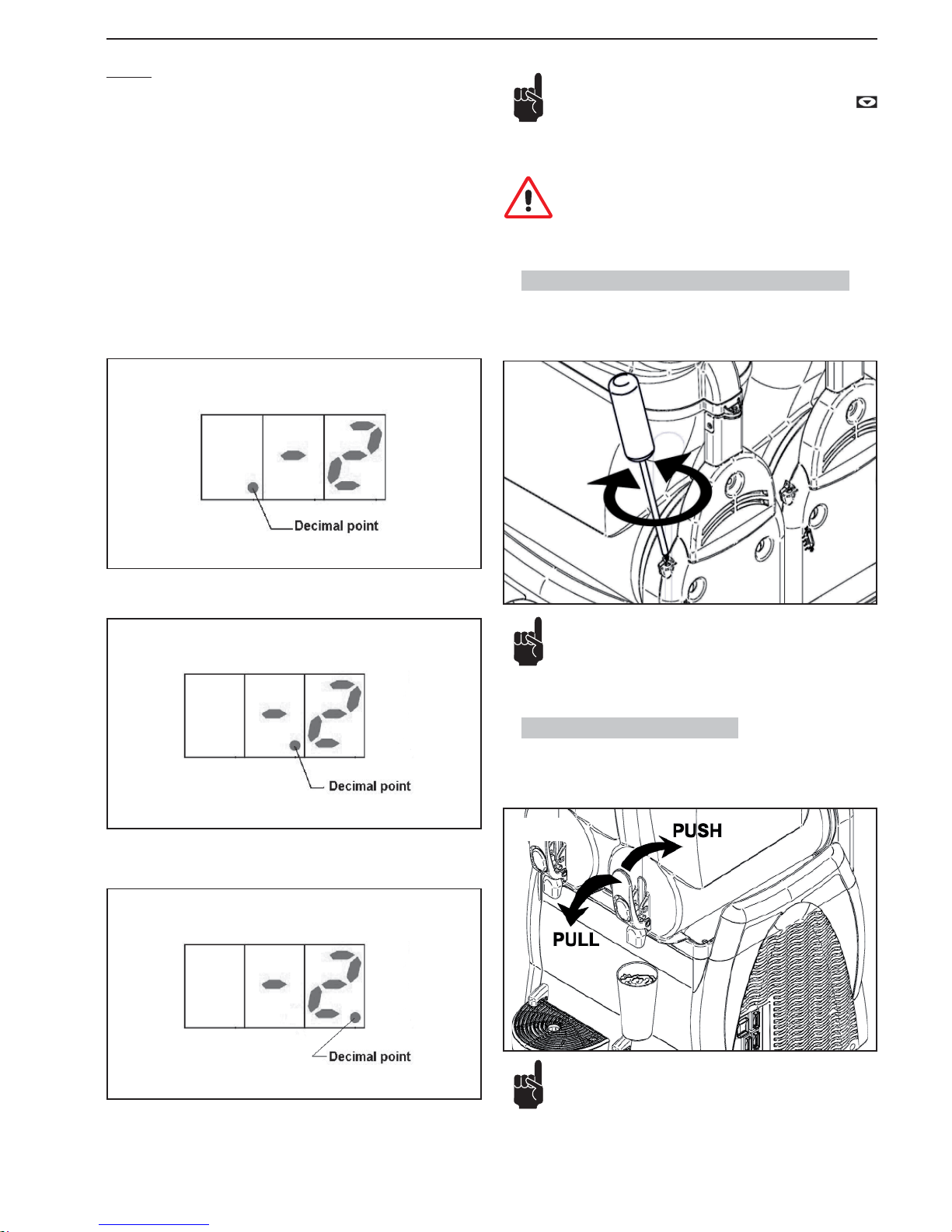
SL310005700 Ed.00 - 04-2011 - 11 _DE-
6.5. Einstellung der Festigkeit der Gramolate
Die Gramolate-Festigkeit kann (+/-) verändert werden, indem man mit einem
Schraubenzieher die in der Zeichnung abgebildete Schraube einstellt.
+: höhere Festigkeit, -: geringere Festigkeit.
6.6. Ausgabe von Gramolate
Zur Getränkeentnahme den Hahnhebel herablassen.
Die Einstellung kann von Hand oder mit einem geeigneten
Schraubendreher vorgenommen werden.
ALARME
Bei einer Störung der Sonde zeigt das Display die folgenden Alarmmeldungen
an:
“A1”: Sonde Behälter 1 nicht angeschlossen
“A2”: Sonde Behälter 1 kurzgeschlossen
“A3”: Sonde Behälter 2 nicht angeschlossen
“A4”: Sonde Behälter 2 kurzgeschlossen
“A5”: Sonde Behälter 3 nicht angeschlossen
“A6”: Sonde Behälter 3 kurzgeschlossen
Während des Betriebs zeigt der elektronische Thermostat zyklisch alle 3 Sekunden die Temperatur des Produkts in den verschiedenen Behältern an.
Der Behälter, auf den sich die Temperaturanzeige des Thermostaten bezieht,
ist am Dezimalpunkt zu erkennen.
Wenn der Dezimalpunkt links steht, bezieht sich die angezeigte Temperatur auf
den Behälter 1 (siehe Abb. 2, Seite 4).
Wenn der Dezimalpunkt in der Mitte steht, bezieht sich die angezeigte Temperatur auf den Behälter 2 (siehe Abb. 2, Seite 4).
Wenn der Dezimalpunkt in der Mitte steht, bezieht sich die angezeigte Temperatur auf den Behälter 3 (siehe Abb. 2, Seite 4).
Abb.18
2 BEHÄLTER
Abb.19
3 BEHÄLTER
Abb.17
Hinweis: Sollte sich während des Betriebs der Maschine plötzlich der elektronische Thermostat abschalten, ist die Taste
zu betätigen, um ihn wieder zu aktivieren. Sollte es nicht möglich sein, den Thermostaten wieder zu aktivieren, die Maschine ausschalten und den Kundendienst benachrichtigen.
Achtung: Während des Betriebs der Maschine muss der elek-
tronische Thermostat immer aktiviert sein, damit jederzeit die
Temperatur des Produkts in den Behältern angezeigt wird.
Regelmäßig die Temperatur des Produkts im Behälter mit
einem Eichthermometer kontrollieren, um sicher zu stellen,
dass sie unter der Konservierungstemperatur liegt. Bei Ma-
schinenmodellen mit Temperaturanzeige oder elektronischem
Thermostat muss außerdem geprüft werden, dass die vom
Eichthermometer erfasste Produkttemperatur der von der
Abb.20
Abb.21
Page 100
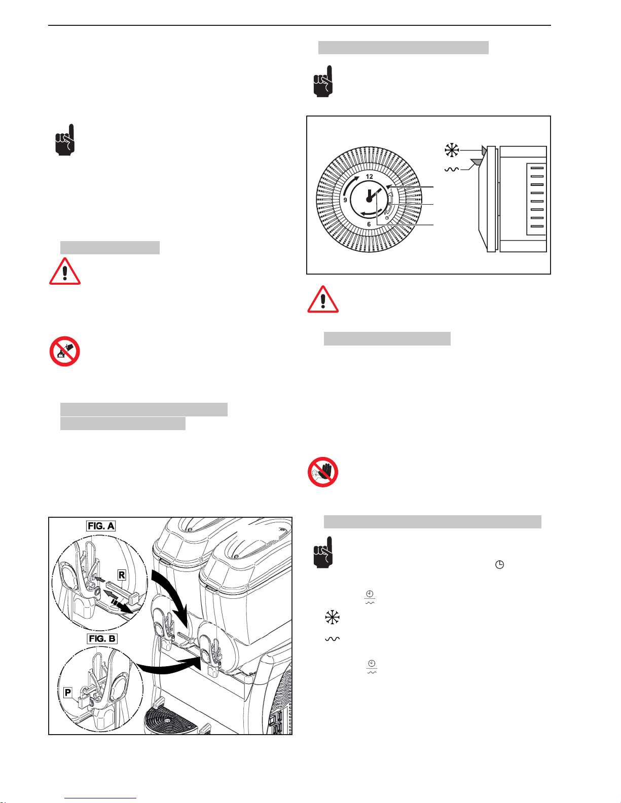
- 12 _DE- SL310005700 Ed.00 - 04-2011
6.9. Sonderzubehör (Zeitschaltuhr)
Die gezeigte Zeitschaltuhr hat nur Beispielcharakter.
A
B
C
Abb.23
Die Einstellungen der Zeitschaltuhr müssen bei Hauptschalter
auf -0- und abgezogenem Netzstecker durchgeführt werden.
6.9.1. Einstellung Uhrzeit
Bevor man die Zeitschaltuhr zu benutzen beginnt, muss man das laufende Datum und die Uhrzeit einstellen.
Für die Einstellung die Skala der Zeitschaltuhr in Pfeilrichtung drehen, bis der
Zeiger (A) auf den richtigen Tag zeigt, dann den Uhrzeiger (C) auf die richtige
Stunde drehen.
Es ist verboten:
• den Uhrzeiger mit irgendwelchen Instrumenten zu drehen;
• den Uhrzeiger entgegen der an der Zeitschaltuhr angegebenen Richtung zu drehen.
6.9.2. Betrieb der Maschine mit Zeitschaltuhr
Bei allen Maschinen mit Zeitschaltuhr muss kontrolliert werden,
ob sich der Wahlschalter (B) in Mittelposition
befi ndet.
Die Maschine muss gestartet werden, wie in Paragraf 6.2 erläutert.
Wechselschalter
in Position “I”:
- Zum Herstellen von Gramolate den Reiter der Zeitschaltuhr in Position
auf das gewünschte Datum und die Uhrzeit stellen;
- Zum Herstellen von Kaltgetränk den Reiter der Zeitschaltuhr in Position
auf das gewünschte Datum und die Uhrzeit stellen..
Wechselschalter
in Position “II”:
Die Maschine ignoriert die Zeitschaltuhr und funktioniert nur zur Kaltge-
tränkebereitung.
Maschine angezeigten Temperatur entspricht. Solange das
noch zu verzehrende Produkt sich im Behälter befi ndet, darf
die Stromversorgung der Maschine nicht unterbrochen und
der Hauptschalter nicht ausgeschaltet werden. Die Maschine
muss in der Funktion Granita oder Getränkekühlung belassen werden.
Wenn die Maschine nicht ständig benutzt wird, ist im Fall
von Milchprodukten wie folgt vorzugehen:
- Desinfektionsmittel auf den Hahn und den umliegenden Bereich sprühen (andernfalls mit einem sauberen
Tuch und Desinfektionsmittel reinigen);
oder:
- Eine kleine Menge Produkt durch den Hahn ablassen,
bevor die Dosis für den Kunden entnommen wird.
6.7. Notsituationen
ACHTUNG: In jeder Notsituation den Ein-/Ausschalter der Maschine unverzüglich auf -0- stellen.
Bei Vereisung die Maschine ausschalten und sich an den Kundendienst
oder an einen Fachtechniker wenden.
Im Brandfall den Brandort unverzüglich verlassen, damit das
Löschpersonal, das über zweckmäßige Schutzausrüstungen
verfügt, eingreifen kann. Stets zugelassene Feuerlöscher und
nie Wasser oder unbekannte Stoffe verwenden.
6.8. Verriegelungssystem zubehör
(Sonderausstattung)
Das neue Verriegelungssystem für den Hahn ist wie folgt zu verwenden:
Abb. A: Während der Verwendung der Maschine ist der Bolzen “R” zu
positionieren, wie in der Abbildung dargestellt.
Abb. B: Zur Verriegelung des Griffs ist der Bolzen “R” in seine Bohrung
einzusetzen und das Schloss zu positionieren, wie in der Abbildung dargestellt.
Abb.22
 Loading...