

Page 1
ooo
.
<ql
CG
159
DETUXE
COTOR
GENERATOR
0
il
Z
0
0
I
[|
]VIANLJAL
Page 2

SAFETY
PRECAUTIONS
When testing
expected
ment.
working
1.
An
the
2.
When
power,
ment or
caucionand standonaninsulatedfloor
3. Dischargefiltercapacitorsbefore connecting test leads
acitors
4. Be sure
can
potentials.
Remove the test
5.
reduce
Do not work
6.
another
shock
against
electronic
high voltages
The
technician
on
isolation
chassis tied to one side of the
be
observe the
and
transformer should always be used
making test
if thiscannotbedone,
metal
can store
your
extremely dangerous and can
possibility
the
alone
person
can
be the
ttre equipment, or
equipment, there is
present
can be
should become
following
lead connections to high voltage
objects.
equipment
leads immediately
close by in case of
Place
charge
a
is in
of shock.
when working
cause of a more serious
be sure to
one
that
good
coming
at unusual
familiar
precautions.
power
AC
hand
to reduce the
could
order. Broken or
expose
after
hazardous
on
accident.
in contact
always
locations in
avoid
you pocket
in
dangerous to the technician.
be
thetesthasbeen
dangerpresent. Un-
a
with the device
on equipment
line.
points,
contact
the
Remember,
accident,
with higher voltages.
with other
as
possibility
frayed
technician
circuits.
defective
that he is
remove
safety
a
of shock.
to them.
test leads
to dangerous
completed to
Always
evenaminor
such as
equip-
having
the
equip-
pre-
Cap-
have
falling
Page 3
TABLE
OF
CONTENTS
PAGE
SAFETY
DESCRIP|ION
SPECIFICATIONS
PRECAUTIONS
OPERATION
Controls
Operating
APPLICATION
Setting up
Checking
Checking
Color TV
Demodulator
Determining
The
MAINTENANCE.
Disassemblyinstructions
Timer Controls
Timer
Making
Circuit
Trouble
Schematic
on the Color
Color
the
and trouble- shooting wirh
and
Adjusting
the
Static
rrouble-
Phasing
With
With
Color
Color King
Adjusunent Procedure
Internal
Description
Chart.
and
King
King
Purity.
Dynamic
and
shooting
Check
Scope.
Vector scope
Sync capabilities.
produces
.
Adjusunents
Parts
List
aoaa
the Color King
Convergence
; .
standard Color
.
.
(separate
Bars
sheet)
.
i
aa
. . .
.
o .
.
.
2
4
4
5
D
7
8
8
9
10
11
15
15
16
16
16
T7
.
L7
18
18
L9
2L
23
ILLUSTRATIONS AND CHARTS
Fig. I
Fig.
Fig. 3
Fig. 4
Fig.
Fig. 6
Fig.
Fig.
Fig.
Fig.
Fig. 11
Fig. 12 - PC
-
Rear View of Color
-
2
Crosshatch
-
Two-stage
-
RCA Bandpass
-
Waveform
5
-
High
-
7
Scope displays
-
8
Ideal
-
Standard color
9
circuits
-
10
Standard color
-
RF Trimmer location.
Board
at
level demodulator
vector display on Vectorscope
layout
pattern.
Zenirh
Bandpass
amplifier
plate
of burst amplifier.
at Red, Green
bar scope
pattern
bar
tube bases.
amplifier.
used in Color TV
Blue CRT control
and
waveform found
in chroma
grids.
PAGE
9
9
L2
13
13
T4
L4
15
15
T7
20
20
Page 4
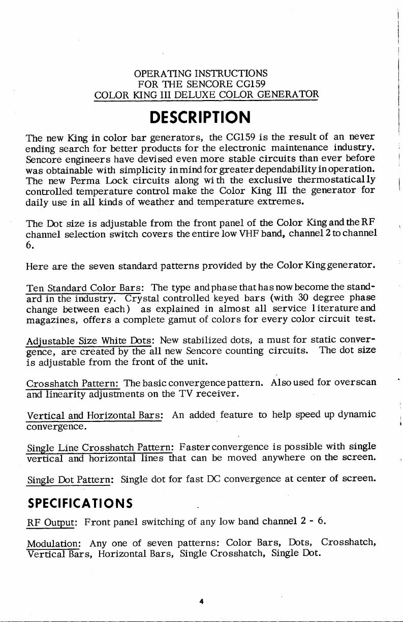
King in
new
The
ending search
Sencore
was obtainable
The
controlled
daily
engineers
Perma l-ock
new
temperature
use in all
OPERATING
FOR
COLOR
KING III
DESCRIPTION
color bar
for
better
have
with simplicity
kinds of
generators,
products for
devised
circuits along
control
weather and
INSTRUCTIONS
COLOR
CG159 is
the
electronic
the
Color
CG159
GENERATOR
circuits
exclusive
King III the
extremes.
result
the
maintenance
of an
ever before
than
thermostatically
generator for
industry.
THE SENCORE
DELUXE
the
even more stable
inmindforgreaterdependabilityinoperation.
with
make the
temperature
never
panel
The Dot size
channel
6.
Here are
Ten Standard
stalcontro1ledkeyedbars(with30degreephase
change between
magizines,
Adjustable
gence,
is adjustable
Crosshatch
@entson
Vertical
convergence.
Single
ffil
Single
is adjustable
selection
the seven
Size
are
and
Line
Pattern: Single
Dot
switch
Color
each ) as
offers
White
creaffiyE-all
from the
Pattern: The basic
Horizontal
Crosshatch
standard
Bars:
a
from
covers
patterns
The type andphase
explained in almost
complete
New stabilized
Dots:
front of the unit.
the
Bars:
P-attern:
lines that
dot
front
the
entire low VHF band,
the
provided
gamut
new Sencore
convergencepattern.
TVreceiver
An added
Fasterconvergence is
for fast DC convergence at
of
can
colors
be
of the
by the
thathas
for every color
dots, a
counting
feature to
moved anywhere
SPECIFICATIO N S
RF
Output:
Front
panel
switching
of
any
low band
Color
Color
nowbecome
service
all
must
circuits.
Also
help speed
channel
King and
channel2
for
used
possible with
center
2 - 6-
to
Kinggenerator.
the stand-
l iterature
circuit
static
The dot size
for
overscan
dynamic
up
on the
of screen.
the RF
channel
and
test.
conver-
single
screen.
Modulation:
Vertical
Bars,
Any one
Horizontal
of seven
Bars, Single
patterns:
Crosshatch,
Color
Bars,
Single
Dots,
Dot.
Crosshatch,
Page 5
9.yrt"t
T@s,
C.-pt*ent:
-
189 KHz
I
I
-
4.5 MFlz
!.00S/ofortimersand
for
sound carrier.
-
3563.795
1
KtIz
Semiconductor
2 - 1M695,
Power:
Size:
Net Weight: 9
L ' 12 Volt
-
105
I0-L/4 x
f
pounds
Complement:
zener diode
25
VAC l}/ffi
4
9-L/2x
inches
-
2N517 2,
14
Hertz,
I - 8 volt
and
30 watts
-
2N4248,
4
I
zener
-
2N52
diode.
OPERATION
THE COTOR KING
CONTROTS
The Color King has three maincontrols. The TVCHANNEL
PATTERN
the
subcontrols, the
HORIZ
justrnent
near
The TEMP CONTROL light is a heating element
a
Pattern
;Elffimposite
willnotjumporfalloutof
The
CTR controls
and the
the bottom of
thermostat
Switch: The
following
ON
switch and the
4.
MHz
5
for
the single line
timer
adjustrnents are alsoavailableas secondarycontrols
panel.
the
for
cold weather
Pattern
sync is
patterns
fed
sync,
are available on the Color King.
COLOR
sound
operation.
syitch
to the modulator
when
OUTPUT control. There
carrier
and
selects one of the
switching
switch
and the VERT CTR and
patterns.
dot
automatically controlled
seven
time3,
at all
from
one
pattern
27
selector
The dot
patterns
that
so
5-
,
the
to
are
1N34A,
switch,
three
size ad-
with
avail-
patterns
another.
Dots: There
l.
T6,r
nC convergence.
have white dots
s€une spot
small
plus
the
2.
Single
DC
convergence
Crosshatch:
3.
Ifies
dynamic
width)
LL7
are
in the center
on the CRT). Static
magnets,
blue
Dot:
visible
are
convergence
and
spaced
lateral
A single dot with
possible
In the crosshatch
on
for
linearity
size dots
small
A color TV
L20
at
positioning
-
only one dot
the CRT scieen.
adjustrnents, over scan
adjustrnents.
that
are adjustab'le in size,
set, that is
of the screen
orDCconvergenceiscontrolledbythree
degrees
magnet.
adjustable
position,
position
to
Thecrosshatchpatternisusedfor
properlyconveiged,
(all
three
around
9
the neck of the CRT,
isprovidedforeasiest
look
at.
vertical
and
adjusunents
guns
13
primarily
will
hitting the
horizontal
(height
and
Page 6
4.
is
vents confusion. Also used
adjust
Single
provided
Crosshatch:
for easiest
purity.
A single
dynamic
crosshatch,
convergence
for
centering
each line
possible
purity
position
-
one
magnets when
ring
adjustable,
pre-
line
5. Vertical Bars: 9 vertical
m@marilyusedwhenadjustingthedynamicverticalconver-
gence.
Horizontal
6.
ffibarposition.Theseareprimarilyusedforthehoriz.
ontal dynamic
7. Ten Color Bars:
@inthecolorcircuitsoftheTVreceiver.Thecolor
output is
displayed on a
front
Color Output
signal that is
sync abilities
most receivers, the
will
lose
pole
effect)
is used to
TV Channel
@1insertion.Inusetheswitchshouldbesettoanyun-
used channel in an
Vertical
cl.ossfiffi-Fattern to the left
right.
controlled with a separate
panel.
Control:
fed
of the receiver. A setting
color sync. This
within
force
Selector:
Line: Theverticallinecontrolmovesthe
13horizontalbarsare
Bars:
convergence.
10
normal
Thecolor oulput control
modulator.
to the
control
each
defective
a
The
area.
bars are
color bars are
set are shown on the
can beturnedtoalmost0
is indicated
color bar.
set to sync while
TV channel
right
or
visible
control. The colors which
It is
by diagonal bands of
The
selector
or moves
in the vertical bar
visible on
generated
primarily
of
200 percent
for
pattern
changes the amount of
used to check the color
percent
100
percent
trouble-shooting.
wi/l
vertical line in the single
the single
position.
TV
the
color
setting
select any
screen,
alignment
will
indicating strip on
normal. Wittt
is
before the set
(barber
color
of
control
the
low
dot
to the
leftbr
when
and
be
color
band
Horizontal
@hpatternupordownormoVesthesingledotupordown.
Power
ffieffi?Klng is completely
patterns
Sound
sound'
primarily
analyze and trouble-shoot the
Line:
Switch: The
to completely
Carrier: The
ca;m-er
to
The horizontaltine
into the RF signal
insure
power
stabilize
sound
proper
switch
solid
on the
carrier
tuning
audio
controlmoves
is used
state, it will
switch is
from
to
screen
the Color King.
of the TV
circuits.
horizontal line
the
rurn the unit ON. Even
take about
of the TV
used to insert
set, but can
3
receiver.
the
This signal
seconds
4.5
megaheru
also be
in the
though
for
ls
used
used
rfie
to
Page 7
TEMP
element
indicator
come
lowandwill
CONTROL:
in the
next
on whenthetemperatureinside
shutoff
Color
to
the
The
Sjng
OFF-ON
when
TEMP
is
on.
fhe
internal
CONTROL
It
should
switch.
the
temperaturels
The
unit
indicator
not
be confused
TEMP
CONTROL
is
approximately
tells when
approximately
the heating
with
indicaror
85o
the
p
po*"i
or be-
1l0o
will
F.
If theColorKingisbroughtinside
temperatures
the
internal
When first
very
rapidly
The
timers
range
so
cause
the Color
OPERATING
To
use
the Color
antenna lead
to
the
sarne channel
switch
Sharp well-defined
for
quality
discuss
steps,
terminals,
Fin-e.funing:.
oscillator.
bone
until
MegaherE
for
andwhitepatterns
(
slightly
Contrast
contrast
convergence
patternandthebackgroundlevel.
to near
the
desirable
zero.
to
trouble-
and sharpness
the
pattern)
ttre herringbone
the TV
dot
brightness
to
ma:<imum.
sizeof
the
TEMP
temperature
turned
it is
on the
once
the
are factory
almost
King
THE
King
to
the
antenna
the
desired
patterns
shooting.
b4efiy
and B.tghtnett
and brightness
how
Color
King
and
the TV
the
Tu.n
f'djust
oscillator
and
favor
thedot
to elimihate
the
is
seen
the
control
also.
v_ers,us
the
adjustrnents
on
ison
dot
On
the
CONTROL
reaches
Limers
temperature
adjusted
impossible
timers
COTOR
simply
terminals
you
have
pattern.
are necessary
Since
of
the
these
TV
and ttre
set
tuned
Color
King
TVfinetuning
in
the color
just
effect
can
now
should
Occasionally,
background)
frequency.
Controlr:
controls
it is desirable
dots,
screen.
the
Y
and
iq{icator
100u
may
starts
towards
to find
to
become
KING
turn
the
the
Color
the
seftings
pafterns
controls
outputcable
to
to color
bars.
disappears,
be
turned
be left
Because
'
on
can
Inthis
the
increase
When
signat.
used
after
F,
usually
not
be
to
rise.
the high
a temperature
unstable.
power
on
the TV
King
for
of the
produced
should
isconnected
the
s€une
bars
control
however,
can
any of
be
until
Backoff
off.
at rhis
be
the Color
the
set
to
to have
case,
of contrast
viewing
Simply
or
achievEO
being
will
stabilized,
switch
convergence
and turnon
.This
the contrast
color
turn
subjected
come
on
after
end
of
condition
to
ON
receiver.
tuned
to.
TV
Controls
by
the
Color King,
be ser.
channel
a9?-O' KHz
the TVfine
is
at a minimum.
is
the
serting
a
patterns,
your
a
highei
Kinghas
liking.
high
may
bars,
the
for
ny detuning
contrast
to very
and
sray
on unril
several minutes.
will
but
ttre
and connect
Tunb
Turn
adjustrnents
In
all thJfoilowing
to
the TV
as the Color
the 4.
best
all of
dot
the
should
tend
it is
contrast
s tabilize
temperature
that would
the TV
pattern
the
will
affect
we
antenni
King.
5 Megahertz
beat
ft6rring-
tuningconff;l
The 4.5
tuningpoint
the
black
conrastrange
ttre
been
designed
seming"oTthe
Howeier,
berween
be
urned
to increase
sometimes
control
low
the
set
and
rhe
will
fV
for
gtre
to
Page 8
TV sets
Vertical
GffifroidTsnotadjustedproperly,
part
number
Horizontal
ffiesatthetopofthepicture.Thiswilloccurifthehorizontal
hold
adjusting
this
Hold: All
of the
of retrace
Hold:
control is
the
effect.
picture
horizontal
color
Adjust
lines,
On some setstheremaybe
properly
not
the
consistent
adjusted.
hold control.
have vertical
retrace
vertical
hold control,
good
with
These can virtually be
A high contrast
retrace
lines can be
vertical
a slight
"fanning"
setting
hold.
APPTICATION
blanking.
seen
for the
or
eliminated by
may also
If the
in the
minimum
"bending"
upper
cause
AND
SETTING
WITH
Sbrring
addition
followed
twocatagories,
into
that
and
catagory
COLOR
The setup
following
the
Checkandset
1.
adjustedwithagoodhighimpedencemeter
meter
2. Check and adjust
pattern
3. Check and
bars
for
4. Check the
the best
UP
COLOR
THE
up and
to a
TV SETUP
this.
trouble-
good generator,
so that
which requires
has a
time
different
convergence
or
procedure
greatest
for
your
of
pdjust
the output
and
static
pattern
the
thatwhichrequires
generator for
TROUBLE-SHOOTING
KING
shooting
will not
trouble-shooting
procedure
should be
high voltage if
accuracy.
the
the
control reduced
convergence
to
use.
color
however, an
wasted. The color
be
the color
of
height
purity
TV is
setup only,
follow
to
TV is usually
followed
necessary.
linearity.
and
check.
this
necessary.
if
magnets.
easy with the
established
usually
eliminate
to
eliminate
to
such as a Sencore
You can
The Coloi
"0"
to
or the blank raster
Here the single
set
usually
done on
done
high voltage
The
procedure
wasted
Color
can be
done
bench.
the
wasted
the
in
the
use
rcing set to
dot
King. In
should
broken
the
in
dme.
home
time:
should be
Field
crosshatch
is ideal
centered
be
down
home
Each
and
Effect
color
is
5.
Adjust
screen.
the dynamic
convergence
controls
for
remaining
the
parts
of
the
Page 9
If
purity
have
TV
Let's
on
may
dotsinsteadofjusttheirowncolor).
patterns
sentable,
switch
first
can see
high
the
voltage
is adjusted
to be repeated
receiver.
seehow
it's side
go
(electron
off
or
from
andyoumaynot
to color
impression
the importance
is not
set
properly
after convergence,
this
even
the
works
as all of
tilted up
beams
Color King
these will
with
the
as
from
(dots,
be
able to detect
bars, the colors will
would
be to
start
of checking for
the entire
following
little
as
gunwill
each
Under
crosshatch,
be strange
analyzing
proper
to
begin with
convergence
affect the convergence
example.
30
degrees,
hit
all three
thiscondition,
etc. ) will look
anything
wrong. However,
or completely
the color
purity
CHECKING AND ADJUSTING PURITY
or
the linearity
procedure
or the
will
of the color
If a color
the
the black
circuits. Thus,
purity
colors
gone,
set is
tilted
of the CRT
phosper
of
white
and
quite
pre-
you
if
your
and
you
and convergence first.
Theadjustrnentof.purityisimportant,
receivers.
canbeused.
position.
it to the
COLOR
the
position.
receiver.
the
the screen
the single cross hatch
purity
rings
and
TGREEN
GRIO
If the receiver has
Some receivers do not have
You
can use
the
Color
antenna terminals
OUTPUT
You will
for
adjusting the
now have
There
control
are some cases
puritymagnets
pattern
yoke
Follow
for
best
2 RED
7
€REEN 6RID
14
ELUE
GNID
2 REO
the manufacturersprocedurefor
results.
GRID
RECTANGULAR
GRIO
rings.
and setting it
fully
clean
a
for
STAt{DARO
t5|tP?2
especiallyin
a set
up switch with
this
King
to obtain
switch or do not have
a blank raster
to the Color
counter
blank
where
clockwise
raster for
you
and the
fire
this adjustrnent for
GRIO
GRIO
the new
purity
a
Bar
to the
setting of
wish
to
ball.
precise
setting of the
rectangular
position,
connecting
by
position.
BLANK
the
know
the center of
you
Here
setting of the
color
this
purity
a
Rotate
RASTER
purity
may
use
purity
of
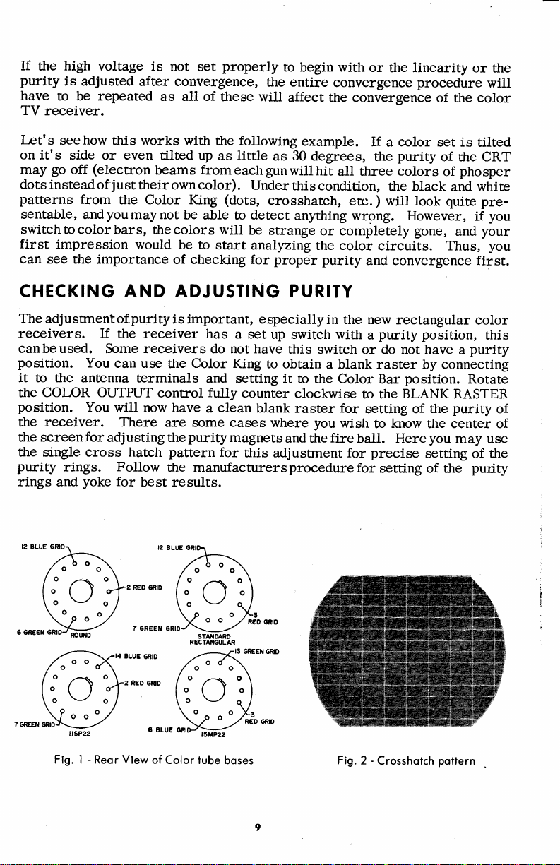
Fig. I - Reor View
of
Color tube
boses Fig.
-
2
Crosshotch
pottern
Page 10

purity
If
CRT shadow
needed.
minute, and slowlymove
motion,
CRT screen and
degausingcoilbanbefound,
external
become
of thenewerrectangular
gause
on the screen.
cannot be obtained
has become
mask
Move the
until it is
coil
magnetized by a
the screeneach
about
turn it off. Onmanyof
some of the built
as
coil
time
I
arge
screen
normal
by
magnetized,
around
the
six
youmove
the screen of
coil
straight
feet
away.
butitis still a
in coils are
magnetic
color
adjustrnents,
which case
in
the
from
out
the cclj.l at right
Turn
new color receivers a built
the
good practice
not effective if the screen
field.
receivers, that
the
purity
You
magnets to
it is
picture
the screen
to
will
also note
it is a
possible
degausing
a
for
rube
with
angles
degause
that
good
get
the best
that
coil is
about
the
to the
with
on some
idea to
purity
the
one
same
in
your
has
de-
CHECKING
Connect the
Position
three
three beam
This is the
center of the screen
Fordynamic
horizontal bar
for
literature
After'adjusting
effect the blackand
differ
an
This
gun, plus
sets
To
but basically
color,
are adjustedfor
cf $e
the
guns
each color set and to
appreciablyfrom
additionalgroupof controlsusedfor black and
group
"background"controlstooktheplaceof
adjust
whereas,
TV
THE STATIC
Color King
dot near
should
for
consistsof separatecontrolsfor
a
these controls
brightness and
hit the CRT
positioning
DC or
convergence the crosshatch, single crosshatch, and
patterns
the set should be
Purity
gainor
B
the screen controls
the B
the bestblackandwhite
to
center of
the
magnets
Static
for
this check.
are used.
make
and Convergence, check
picture.
white
the
drive, G
you
gain
contrast controls.
AND
the TV
convergence. NOTE: The dot must be
ttrese adjustrnents to specifications,
circuits
or drive, G
and
screen. The electron beams
the
the same
at
the blue
and
Dynamic
followed.
These circuits,
found
gain
or drive and CRT bias control. In older
should refer
are adjusted
gain
picture,
DYNAMIC CONVERGENCE
set the
pattern
point.
lateral
procedures
all of the
in black
white
the screen voltages on
gain
theB
to service
for
drive
or
throughout the
switch to single
If they do
magnet
are
circuits
in color
white sets,
and
tracking
CRT
and
literature
equal
CRT
and
slightly different
not,
until they
vertical and
the service
TV
sets,
adjusunents.
bias
for
intensity
bias
normal range
dot.
from
all
adjust
which will
except
each CRT
the
do.
near the
do not
for
controls.
the set,
of each
controls
Other slight differences in color TV circuits
supply
supply and
to
reduce blooming and loss of convergence,
wider
a
IF response
to
pass
the color
are a regulated
separate
a
information.
high voltage
focus
voltage
Page 11

COTOR
The trouble
in order
fault. If a standard
eliminated
circuits
TV TROUBTE
color
in the
reduce
to
service
and
TV:
of the
SH
TV should
wasted time
procedure
will be
OOTING
be isolated
checking other
followed, then
is
faster. If the
to
the section
circuits
much
u:ouble
appears
giving
that
wasted
the
may
dme
in the
trouble
not
will be
be
color
at
for
1. Check
problems
2.
Check
white
If
the
the
of
are
different
functions that
Bandlass
@l,thebandoffrequenciesfrom3to4.1megaherz.A1l
of the
3.58
iskeptinphasewith
with thecolorburstswhich
provides
Demodulators:
ch-Lomilignal
6e
CRT. In some
the
directly
amplified
grids.
are
results
rtre CRT
Sencore
the
good,
is
circuits
SM152
generator
ilignmenr
show
goodalignmentcurve, thenatrouble
a
the
by
problems
chromacircuits,
needed
circuits
Amplifier:
transmitted
Megaherz
rwo
from
In ttre
both
are
CRT
and
proper
for
then the
picture
should
and
or SM158.
appear
of ttre
up the
in R-Y, B-Y, and
fed
high
weak
and
are
find
to
they
Reference
signals separated
The demodulators beat
the
new
into the same amplifiers
the s€une in all
tracking
Champion.
circuit
some
black and
problem
is not
be checked
If the vertical
weak
IF circuits.
frequency response
smeared
indicated
agood
the
in the
perform.
The
color information
the original
from
of the
demodulators.
solid
white operation.
good,
ttren the
and
vertical
in the
color bar
trouble.
chroma
bandpassamplifierisused
Oscillator:
are on
by a 90
the bandpass
newer
G-Y
state receivers,
three systems.
emission
and
CRT
Some
problems
is in the
carrier at the
problem
with
a sweep
lines
smeared,
fast
The
lines.
chroma
amplifiers
generator
following is a brief
The
section
is within this
The reference
ulator
horizontal back
the
degree
the reference oscillator
amplifier to
receivers, the
In
other
and then
with
problems
can look
If the black
chroma
generator,
on the
this
dme
rise
the
of
the
in
circuits,
of the
circuits
transmitter,
phase
receivers,
before being
the color signals and
CRT checker
a
can
CRT
like
circuits.
probably
is
cross
is also an
of the vertical
TV
receiver.
video amplifier
then a
goodwide
and
color
to separate
band.
oscillator
the
of
porch.
shiftfor
produce
gun grids
color
the color
to the CRT
like
look
problems.
white
and
If the black
the RF
in
such as
hatch
good
TV receiver
applied
the
pattern
indication
If the
is
understanping
band
description
and amplifSr,
is
TV set.
color
controlling
by
The oscillator
demodulators.
the
signals
signals
color
are driven
signals are
to
the
cathode.
such as
circuit
picrure
and
or IF
Sencore
the
of
poor
of
will
line
has
IF
indicated
scope
of the
the
and
used
against
for
the CRT
Y signal
The
to
It
it
Burst Am
lifier:
The burst amplifier
signal
to control
separates and amplifies
the 3.58 megacycle reference
the burst
pulse
oscillator.
Page 12

Color Killer:
,co-6Ei-gnal,
oT a
ouqput
Phase
ampilTier
reference
of the
Detector:
wiT[
oscillator
The
color
killer circuitproduces
to cut
phase
Thephasedetectorcompares
the
off the
detector.
reference
signal
band
oscillatof
and,
also
negative
pass
controls
a
amplifier. It
the burst
signal. It controls
the
color killer.
bias, in the absence
controlled
is
signal
from
the
the
phase
by the
burst
of the
To
trouble-shootthesecircuits,
pattern
such
as the Sencore Model PS148.
Let's start
(See
Figure 3),
Waveforms
each
at
Some of ttre maindifferencesbetween
color
up the
(2)
Zenithhastheburstpickoff
amplifier;
the burst signalappearsattheoulputof
RCA
it is
cathode,
applied to
constant during
goodwideband
and
a
with
the
bandpass
whereas, RCA
(W1,
W2 etc.
input and oulput of the
from
input
picksoff
RCA
gated
out because of
(4)
Zenithhas
grid
the
minor
@
l,5nc
t nnl
mnt
3,t
)
video detector;
the
the
an additionalfeature,
first
of the
changes intheamplitude
you
service oscilloscope
amplifier.
uses a single stage
you
that
amplifiers.
afterthe signalpassesthroughthefirst chroma
burst at the input
positive
a
amplifier
*
@
l?x
ffi"
r{Pt,I
{ iltls{rRtD
-lvl
lllllllll|Illl|rl
need
the Color King
Zenithuses
should
get
the circuits
RCA
the Zenith
gate pulse
which
set to the color
with
with
are
from
to the bandpass amplifier{3)
amplifier,
(Automatic
ACC
keeps the
of the incoming
@
6AU6
ornfrA
zil0
rr
low capacity
a
two stage amplifier
a
amplifier
the Color
these:
the
applied
8tl{tPtss
(See
King
(1)
first
video amplifier,
whereas,
to the amplifier
grain
ArP
*,T/I
=
toitz
I
/ nrilxlts
|lrPuI
Figure 4).
are shown
Zenith
Color Control)
this stage
of
color signal.
D{:il(x)
rc
t-Y
Dtru0
ffiiliilltl
ffiililllu||lill
bar
probe,
picks
in the
I
I
I
)
I
I
-
Two-stoge Zenith
Fig. 3
*vottlct
wttx cotoR stcult
Pttstu
Bondposs omplifier
Page 13

I
t@
Cot0R titRJT\
+F
.-119r-
I
5r v tDto
TO EURSI
AilPI.IFIIR
The
waveform
l6 mnl
t20
@
011
at
the
FROII
8UilKtn
CATHCDI
plate
signalwillexistonlywhencolorisbeing
King
to
line will
ablackandwhitepattern,
still
show
traces
Fig.
0*flA
-
Fig.
4
of
of the
-
Woveform
5
@r
t/2
6EA8
BAiltpASS
*
votTlGt
RCA
Bondposs
the
burstamplifieris
the
horizontal
AtP
1.,'f
t35y
yilrH
@tot stGIAt
transmitted.
burst
plote
ot
I
265v
omplifier
will
gate pulse.
of
burst
pRtSENt
shown
If
disappear,
,-
omplifier
in Figure
you
swiich
although
@
',rJf,,,,.,,
5. This
the Color
the
base
color
Demodularor:
The following
schematic
(Figurc
ffi,usedinsomJoftherecentc-olo'""t,.Intheolderlow
type
level
3.58 MHz
applied
bandpass
of color
reference
to the
amplifier
theresultantdemodulatorcolor
directlyto
shown
grid,
the
heremakesuseof
but two
demodulator,
grids
of the cRT.
alsobeats
grids
of the
supressor
oscillator
againstthe
CRTwithout
atube having
grids
and nvo
the
color
and then
In the high
signalsare
additional
a single
plates.
information
amplified
level
3.
58 MHz
high
control
All
in
rype,
reference
in
amplitude
amplification.
three
6)
is a high
was
additional
the
grid,
grid
cRT
level
beat
against
stiges,
signal
oicillator,
and are
The
a iingle
sifnals R-y,
type
and
from
coupled
example
screen
the
the
but
Page 14

B-Y and
90
G-Y
degrees
veloped at
picks
up
applied
using
to the
the
aredeveloped
phase,
out of
plates
the
the average
greencRTgrid.
color bar
pattern
Fig.
atahigh
fed
are
are the blue
current
The
from
-
High
6
level
3.
amplitude.
the supressor
to
red color signals.
and
58
flow, which is the
waveforms are typical
King.
Color
the
demodulotor
used
in
MHz oscillator
grids
and
The screen
green
signal
of those
TV
Color
signals
the
and
found when
signals,
de-
grid
this is
The waveforms
waveforms
the
megahertz sine
literature
vice
ouputof
are
the demodulators
shown in
Figure
*l
Fig.7 - Scope disploys
the oulput of the
at
3.
58 megahenz
reference
at the oscillatof inputs to ttre demodulators
wave
signals and are
for
the
amplitude
or at
present
of these
the CRT
times. Refer to the ser-
at
all
signals.
grids
in those sets that use amplifiers
7.
t234567891O
Red, Green
ol
ond Blue CRT
t4
control
oscillator
continuous
are
The waveforms
grids
at
3.
and
58
the
Page 15

UOMnOOW]O
CN|SVHd
))1H)
le
eqJ
lnq
.Burseqd
'uJen€d
qtlrn
ueev\
eJeq1
sarlnbar
'JUO
sJeJn
s/dorls
Eursn
e{Bu
aJ€
e
eJe
eql
oepl^ eql
EufX .roToC
f.rarr adocs;olcaa e
adorS
JUC
p1rE
srtDuIlBq1l\etuos/t.rBA
eql esn
padal
tuJoJele^\
'rolcelap
aq uec
tcaruoc tsnf
Sulseqd eql
lnq
lsun€
pasn
eql
{oeqc
'dldurrs
adocsollloso u€
sureued
eql
eurBs eW sfB^\IB
Joloc
pecnpord
dplclnb ot
pue
na
roloC
aq uec
EUI)
aqt ot
epetu
tes
qtl/r\
eseqt e{€ru ol
lecpuepr
q
esoqt
JotelnpowepJosadrtllueJeJJrpIBJeAas
ampecordtuara;;rpr(pq311s
-ro;
.s.tuloSaaBl\
ldecxa
.rBq
eql JoJ
eqt uI uJellBd
eqf fq
Joloc
"rBq
A-U
{ceqc
f11sea
pu€
apIA\ napEe.r €
'stuaurlsnfpe
/dou suatsfs
Jo
luaunsnfpe
eql ol
peluesa.nC
'apnrrldue
€tuorqc
U
sB
'u.ratled
eLF
eql ol urnl
pu€q
peecord
amElg uI urloqs
'4
ur
'esn
;edord
Jo
splrE
ITB
rsotulv
'sunJr-rc
sB
'3u1seqd
aqr
aq
ppoqs
rot€Inpotuep
req roloc
adocs
.ro
'eloqe
qc?e pue
,(aqJ
rolos
-lJeJnuEIu
6
arnElg
uees
6.FtJ
-
I
-
'6tl
(1s;ng;
pJopuols
rolof,
loapl
ropa^
adors roq
9l
.toToC
uo Aoldslp
s.IPg
punot ulJorelo^
u!
adorsrolral
Durorqf
sl!nlJ!t
Page 16

With
With a
well as the
you
with the vectorscope,
methods.
and
in
bar
sixth
phase
vector
bar to
90
greater,
on the
the
VectorscoPe
Vectorscope
otheradjustmentscanbe
monitoring both the
are
The vectorscopeisconnectedto
setforvectors.
Figure
8. The
pattern
bar of the
adjusted
patternshouldpointtotheR-Y mark on the scope screen
B-Y mark. This represents an
the
degrees
andthe
scope screen,
newer receivers.
third
or the red
color bar
properly
found
as
sixthbarfallshalf
such as
Thepatternon the scope screen
in
it indicates
the Sencore
red
and
Color King is
the
barof the
signal and
pattern
and the
most of the older color receivers.
vector
and
tint control
way between the B-Y
an
PS148,
accomplished
blue signals at
connected the same
pattern
the sixth bar
is the blue signal.
of
angle
the
faster
the red and blue
is
of
centered, the
between the
angle
105
degrees as
demodulator
the same
should appear as
the third bar
the
easier because
and
time.
as
grids
vector
With the
mark and
pattern
third
red and
If the angle
found
in the other
of
demodulator
and
phasing
To use
of the
shown
color
the
is
bar of
the
blue of
7 mark
the
most of
on
as
CRT
the
the
sixth
is
DETERMINING
The colorTVreceivermay
colorsmaynotstayinsync. This
secLion are synchronized
horizontal
of
ability to sync
color signal may not
ation.
reduce
stay in
viewing the color bars, the colors
weakly
color killer or
given
in the manufacturer's
color circuits
syncpulse).
To check color
the CHROMA
sync
to a
visible on the CRT. If
COTOR
NewcolorTVreceivers
when
installed.
present
be
sync, after
setting
least
the 50
burst amplifier should be made
defective.
are
sync
from
from 100
percent
service
SYNC
perfecdy
is because the sync circuits
the
Here
from
they do
THE COTOR KING PRODUCES
Thecolorbarpattern,
comethe standard of the industry. It
justing
eliminating confusion
The
ing
minus the
that is
color TV circuits,
principle
at a
behind
frequency
horizontal
constantly changing in
usedin the
guesswork.
and
this tlpe
3563795 Hertz
of
frequency) wlll
line
above
because one
pattern
of
(
the color carrier
phase,
CAPABIIITIES
horizontally
3.58 MHz
where
is
the TV
adjusting
should stay in sync
literature.
the TV
percent
calibration
not
stay in sync,
STANDARD
trouble-shooting
is simple to'use
pattern
is simple.
appear as a
when compared
vertically but the
and
color
sub-carrier
shouldbe
Color King
the
station, at the
zero.
to
point
according
If sync cannot be
checked
time of install-
good
for
set
The colors should
on the
long as
as
adjustrnent
to the instructions
COTOR
procedure,
for
analyzing and ad-
covers
An
oscillator that is operat-
frequency
full
the
3.
megahertz
58
3.58 megahertz
to the
in the
Chroma
(back
porch
for
their
handy,
is
color
control. When
they
of
held,
as a
bars,
are
the
the
BARS
has
be-
color range
357
9545
Her tz
signal
t6
Page 17

IIB
f[
aqr
aseqd
Bulrnp
.daaryrs
ur aqnl
aloN
sr sIqJ
cuds
loJtuoc
a3uereJeJ
09tjo
Jo-a8ue.r
E
lBql
sroloc
eqt
sJoloc
Jo
Euprui3aq
euo
tI
ueqr
Eupe8
aq]
rgtuo4roq
esn€caq
ispd
pue
-uds
pruozrJoq
eql
gg.t
leuErs
ror"nt""o
iog sae-rEep
sr
erues
eqr
III^\
9s.t
daarns
gei-rede""erE"p69
leturou
euo
.snql
qcee
pacnpo-rd
eculs
aqt
daams
sr
BuFr"rr-d"a^s
eq osIB
punoJe
Burte.rado
tsmqpareEZl eqrJo
Jo
aqt
sl
aspd
pue
zTtaqeaevs
ur
aqr
eseqd
sde,rtp
orez
qlln
re
otez
zueqeEiw
roloo
.fcuenba-rg
aql
Joloc
daqt
.tes
0I
,(Fo
slsJnq
.peteurturle
acueJeJeJ
'AJ
Ftuozlroq
'snqJ
Jo
auII
qceaBulmp
ecueJeJJrp
}I)
.otez
eqr
tB
rorellrcso
e
lpn
^\oqs
lB
srncco
aqJ.
retno
eql seuoceq
aJeqt
'dae.r*s
Ietuozrror4
uee^\teq
eql
eseqd
ecuereJJlp gseqd
;o
SuruurEaq
uec sJBq
.urnrlcads
;eadde
eql
Jolellrcso
dcuanberJ
eq
ueq.A,\
se
eql uo
etuBs
srncco
cuds -ro10c
eql ur
B sr
'eurl
qroq
lB
aqt
lxeu
eql
71
pacnpo.rd
pe,trell
ur ut\oqs
a.rntcrd
eqnt
eturl
'tsrnq
na
'tes
alelduroc
e
'a.ro;a-raqa
eurl
qceg
srotBllrcso
699
sa8ueqc
Eupu$aq
'deerns
setun
t€ql
se
raq8rq
e.rB
eql uo
e-rnErll
'91
roloc
eql sB
flerelpaturur
sr
qcrq^\
aEueqc
ur
elalduroc
sfeldsyp
le
eql
seer8ap
J9
atD
'('cla
ueql
dpcexa
eJrucld
'sreq
IBIUOZITOq
aql JetrB
ot
pasn
0l
-
'6tJ
I
oo
e
ttll
.oc .o9
.o9l .ozl
.081
I
ttrl
.oo€
.uz
grz.oz
propuols
urellod roq rolor
])NVNlTNIVW
sNoll)nulsN
eqtelourer
o^\t
aqJ
'esec
eqt Euraourer,(qpar$IaqfetupreoqCd
xts
fernepreoqeqtpueqfldurls
erLT.
'pJeoq
eql
JJo
reteeq
pue
Eur.replos
tt
puB
d1l uo.rr
eql
'ado.r
lB
sx\ercs
laued
s/dercs
lrun
eqJ
tsureEe
dflgelssod
dot aqt uorJ
III^\
eEeurep alqrssod
eqr
yo
Jo
dot eql
punore
aq
preoq
erp
eq r\Ou z(eu
eqt
'ta{cerq
,t1py
plnoc
a8etuep
laued
pue
JO
lno
peUII
oJ
'preoq
III^\
sIqJ
IBuolteredo
aq deu
t€tsor.uJer{r
JI
tlnseJ
Elun
'u/r\op
paceld
eqr
rI
uI
eql
eqJ
oA4t
asec aql
^\oII€
slql
tsupEe
Joleeq
suado
JoJ
sr
11rrn
Algwlssvslc
I
.69ICJaqtelquessesrpoJ
eql uo
s^\arcs
.ruonoqaqlletaE
a.rnsodxa
ot
.uoltTpuoc
ado.r aqt
.uo
eqt daal
J?.,er
'Eurcraras
qroq
eg
ueq^{
aqr 3u1ce14
.ralBe{
Jo
Jo
seprs
InJeJec
Jo
edo.r
eql
eqr
'Surcra.ras
Page 18

TIMER
The
KHz
lockedpattern.
ponents
front
component
the
CONTROTS
Color King
crystal
so
that
panel
aging. These
panel,
front
timer
to the
controls
15,750
Thecircuitsare
instability
if necessary.
system has
and
component failure
and
you
allow
adjustrnents
been designed
6O Hertz
simpleandhave
to
retime
sync
the count down
can
be made with
to count down
signals needed
minimum
a
will
be at a minimum. The
from
for
number
circuits in case
screwdriver
a
188.8
a
a stable
com-
of
of
from
The three
panel
Horiz, Hold:
Ts aajffi-Ior
14
and
Vert Stability: Controls
It is adjusted for
controls
know
itsrangeonaworkingTVreceiver
it in the
TI'\'IER ADJUSTMENT
If
adefective
have
controls.
ceiver.
Using a
receiver to a station
trols.
1.
driver slot
2.
control further
between this
timer controls
and are
if the raster
whatyou€rrelooking
to reset the internal
Set
Turn
the control
plainly
This
are simple
future
componenthas
The
large
screen
thefrontpanelcontrols
the Horizontal
marked.
is similiar
13
lines
pulled
is
a steady
and
should it occur.
procedure
TV
signal
and the
back until
until
point
and the
are
to the horizontal
visable under normal
in.
the
stability
pattern
easy
for.
PROCEDURE
beenreplaced
range
is simple
receiver,
and
white
mark
control
the
pattern
the
located
to
It is
center
to the center
paftern
first point
on
or
without
adjust
good
a
to see
adjust
and requires
either
the horizontal
on the
on
PC
the
stabilizes.
losses
lower
the
vertical
any roll through
and should cause
idea to turn each
effect
its
inone of the timer
controls
black and
of their range using
panel
board fully
sync
for
right hand
hold control
conditions
roll through
so that
to recenter
onlyalarge
white
and vertical
guide.
as
a
blockwise. Now
Note
again. Then
best range.
this
corner of the
TV
of a
proper
of
or
no
control through
you
stages,
or color, set the
point.
receiver
overscan
pattern.
the
of
wiggle.
problem
wilt
recognize
you
front
the
screenTV
hold
screw-
the
Turn
back the control
The
you
if
may
panel
re-
con-
turn
the
Center the Horizontal
3.
4.
Adjust ttre
60
Line
Hertz controlfor
control
and the
the slowest
pulse
pattern
control.
wiggle
or
roll
through.
Page 19

5.
Adjustthe
TV
screen. Sbt this control
lines.
until this
this control has
controls
If the
MAKING
horizontal line
pattern
movement
interaction
was
as
COTOR
done with
KING
controlwhile
for
has
disappears. Note
slight
a
with
Horizontal
the
ADJ
observing the scanninglines on the
16
scanning
movement,
the Horizontal Line
USTMENTS
lines
adjust
the number
control.
between
the
scanning lines
of
control.
horizontal
pulse
Center
control
as
a1l
Dot
unit:-edotsizeadjustrnent,
linesinthemultiple
thedots,
the dots should
should adjust
pattern
tobe surethatyou
Color
adjusted,
gr€rm.
correcrion voltage
referenceoscillatorintheTVuntilabeat
are
pattern.
still
color bar
twice.
Single
realized, and alsothatthevertical line will not
is
TV
To
that
controlsfullyclockwise. AdjustR46sothatthe
nvoinchesfrom therightedgeof the screen. Adjust R53 so ttrat the
line is approximately one inch
The Color
Size:
themorereadilyyoucannotice
on a TV set.
Frequency:
withoutlaboratoryequipment, by using the burst
Tune in a
holding sync.
With
disabled,
pattern.
Vertical
screen and
these controls, disptay
adjust
has
properly
a
King dot
dot, crosshatch and vertical
not
made
be
the dot size trimmer
have not made them so small that
The color sub-carrier must
color
to the
Connect
correction
the
adjustthecolor
For
Horizontal
and
the horizontal line will not
centered raster. Turn
size adjusffnent
C32, changesthe
so small
After
adjusting
program
3.58 MHz
the
voltage of
phase
reulsts,
best
.ines:
T
from
that they are
on an operating
Color King
adjusunent, C24,
the single crosshatch
the bottom of the
is accessible
width
line
error in convergence.
the
your
to
the dot size,
oscillator in
is seen
you
The
full
at
difficult to see
own
be
in
to the set
3.58 MHz
should
single vertical
range of the
go
go
off the bottom of the screen.
the VERT
vertical
from the
the dots and
of
patterns.
while observing
liking
check the
will not
they
quite
accurate.
color
TV set and adjust
the
picture,
the
and
oscillator
for
go
through
front
off the
pattern
LINE
line is approximately
screen.
The smaller
clearly.
vertical
from
a
set. Remove
or
adjust
in the
zero
a
this
horizontal lines
and
panel
right edge of
HORIZ
and
front of the
vertical
However,
You
the
line s
be useable.
It can be
pro-
color
the
the
the colors
for a color
TV
set
beat in
procedure
on a TV set
horizontal
the
controls
the
LINE
RF Adjustrnents: The trimmers
of theColorKingonthe top
with a label
RF
The
required,
on the inside
trimmers
following
the
should
PC
figure
and
seldom,
procedure may be
for
mounting
11.
ever,
if
RF
the
adjusrnents are
bracket.
needs ad3ustrnent.
used.
The
located inside
trimmers are
If adjustment
marked
is
Page 20

To
adjust
strengthmeter
each trimmer
field
the
ments.
the trimmers,
strength meter. After
A slight interaction may
may
such as the Sencore FS134.
for
best
lou
color
or ma:rimum
use a known
adjusting each
be evident.
good
TV
with
Start
signal at the carrier
channel recheck
receiver
channel six
field
or a
and adjust
frequency
your
adjust-
on
cH.
Fig.
@
2
| | - R. F.
Fig.
l2
RF
@
3
-
JUST
AD
Trimmer
P.C.
uE
@
4
Board
NTS
@
5
location
layout
@
6
Page 21

lln)ul)
NOlldtu)s]o
eqJ
orlJ
dq
Jo
*
l
I
t
7IU
.roy
eqJ
?TC
sTrIJ
69ICC
alqels
aql
sapp
aserp
.rolefiIcso
Sulpaca.rd
saEets
puB
prre
laued
turoJ
ptuozrrog
fecpral
.radeqs
oluT Luaql
rotellrcso
e1Eu1s eql
letuozlroH
j31ilt5?:
JoJ
su;elled
,,treeq,,
Jo
aqr
alqe1s
tern
sr
a3ue.retD
arnteradual
ZID
.Jot€IIIcsoIecuJaA
.lueunsnfpe
Jo
uortesuedtuoc
lBluozIroq
eurl
eqr
dool
>lceqpeeJ
lo
r{rlllQels .ralea.rE
sesTnd
saspd
gga
.gUJ
eqt
au11
:iff
-radd11c
sraluua
lBJrt.raa
"H"
11I
8uI) rolo3
sI
acuaEJeluoc
aqa
.{ool
ale.radosa8els
eqlul
pezruoJcur{s
pue
,gU .l,U .aEets
eqt
aqt
sI
esern
are
ruorJ
'gUC
eJB
eurl
e.re
seslnd
fi
"t1"
sretup
.TIU .ZIUJotslsuocpu€sJeilrtue
asaql
tuauodruoc
eslnd{ceqpeeJ
pue
VZota3ueqcorJotBIIIcsoeuII
paldnoc
9UJ
sazrpnba
,
eqJ
paldnoc
613
pue
ua>lel
""9t"
ernlrurru e ,(lpcrseq
Jo
pue
aqtsrrot€Jaua8
Jo
rndrno
aql
saEelsu^\oplunoceqtolulpaldnocpuegga
eurcs
dq
6U
euIIleluozlroqaqtroJ
renltuaqoeg
SI
sI roteilIcso
dool>lceqpeaJrotrncrlJIBuoItIppBuB
qcea
IBcrueA
'sunJJIs
r.uo4
q8norqt
'Jeuueru
aql
au4t eqJ'uortesueduroc
roJ
gOpue
stuauBsnfpe
'Eufe
esn€c
eqr
er.uF
B
pue
913
sadeqs pu€
erues
U
IUJ
orul
aqt o1
a13urs
ruorJ
rTjt
HI^:
Supooqs elqno.rl
zH)g'ggI
qsllqetsa
rolelllrso
aABq
eql tuorJ
pue
aqt
o'
lelsdrc
p1s.{-rc
eqJ
clseq
Sururocur
'leale.radollT,\{
aql
B
leluozlroq
tuorJ saspd
rn
saspd
aqr
ur€ru
4UJ
sI
eqt
JoJluelsuoc
pue
'ZZU
apB\
luareJJrp,tpqSqs
lecrlJal
cuds
eurl
reultua s€UJ
9eU
olul
cuz(s eql
raSSIrr
IBluozIJoH
Jotoelloc stUJ
are
as
s
tIU'TIU'elqelsnfpe
tuorJ
'.raulursu€.rl
IAaIel
uors
Jol€IIIcso
IUJ
Jolellrcso
pue
'tUJ 'tUJ;o
trncrlc
eql uoJJ
sB
pasn
letuozrroq
q3no;qr
oc
sJolBIIIcso
tZU
pue
ZZEpue
aBuer
pue
eql
LI Jotunoc leturou
eqt
p
st
puErs
/IO
eqt
aseq
leluozlro[eql
dure
euII
q8no.rqr
a1 dn
p
""H1
qclql\
sI
'SUJ
B sr
SIC
srolellTcso
pue
Jo
pue
qEno-rq1
aspde
-o.rd
.radeqs
apolpB
aJB
!roreglcso
'tTU
aql
roJ
e se
eq uec
o^u reqlo
ZUC'rotelllcso I€cnJeA
pue
feluozrJoH
'petereueE
sapuo.rd
/ZU
pue
cuds eql
Eulldnoc eroJeq saspd
Iecrlral
ttC
JoJ
'roterql^plnur
-qJlers
s
ur
s
ru 04
Eupe.raua8
'sJelreceJ
padeqs
qJBg
Euqcolq
ro
Eupunoc eql uo serq
.roJ
eql uI
tuoJJ
pesn
qtl^\
tr
V
areE
eqJ
'tUC
zHIAtr
zHI
eql
793
q8no.rqr
zH)lg'ggl
TIUJ
aqJ
0I
aslnd
zFDIg'ggI
q8no;qr paldnoc
ruroJ or
69g
puErs
9S't
feu8ls
reqt
sI
sr
puEls
eqr
eql ol
sr
peleE
tuorJ
'slop
a8els radeqs
plsdrc
peldnoc
uo
urenBd rBq roloc
uon3unJ
paldnoc
pue
lBr{l
sI
eqt tuorJ ue{el sr
JOCI laued
i1ZlS
aums eqJ
qcll^,\s
Itc
q8no.rqr
aspd aqt sadeqs
e3ers rotell1cso
LZJ
qEno.rqr
eqr dq$o
peldnoc
rt
pu8rs
ol
.rotoelloc
eq]
turoJ ot
olul
pue
SIUJ
zH)8'88I
eql
Jo
luau[snlpe
aql
tuorJ
'TIUJ
saldnoc
sespd
uopcunJ
ZUJ
ZtD
JOCI
IBcuJe
tI
are8 .roloc eql oul
ruorJ
g71S
'seull
.radeqs e
eqt otul
'tUD
'qclp\s
aEels Euldeqs
aqr
qEno.rql
sI
'a8ets
roloc
snonuuuoc e sat€reuaE
eqJ
IIUJ
pue
apolp
paldnoc
etues eqJ
ale8
9S'€
9S
't
Eullea.rc
Page 22

The vertical line
vibrator
lines
TR15
dot signal is taken from
acitors
generate
controlled
are
and mixed with
to
the
delay multivibrator
the single crosshatch
with
function
R48
the
vertical line
CRs,
switch.
R58.
and
and both
the horizontal
and
the
and
The horizontal
in
the collector circuit. The
signals
single dot
are
line
line
coupled
patterns.
is inverted in
delay
mulri-
The
single
through cap-
The
signals
coupled
and
the syncfromTRStoformthe
downbyRT8
TR19
panel
front
C54
to the
duction, changing
signal to be
power
The
with double
recrifiers
trigger
12
volts
regulated
transistorTR9toaposiriveT.4volts
The
heater
thermostat
physically
the-surroundingtemperature
and hence
are selectedfor
from
andR79
frequency
channel switch
diode
fed
supply is
regulation
CR6
arnp.
for
the color
12
volt supply
R68
THl.
located
the
turn
function
the
to the
is controlled
modulator
its impedance
to
the output
a transformer
CR7
and
R70
and
oscillator
with
the
ResistorsR65
on
top.
on
and
the
complete
diode'modulator
by
54.
CR9.
cable
for
the counter
is dropped
zerer
CRll
further
is
indicator
The
control
off
of the heating
desired
switch
The
to CR3
Ll
and
resultant
The
to the RF
for
isolated full
by R69 to
further
and shaper
regulated
for
light
and
R66
heat
caused
the
pattern
video
C55
video signal varies
injection
stages. The
all other circuits
1l
in
opening
on the TV
clipper stage
signal. The
CR9. The
through C59
RF energy
signal, causing a modulated
into the
wave
*25
a
drop
the voltage
stage
and RF
zener
by
across
series
element
by
with
these
and
R6g.
receiver screen
and
signal is
RF channel
selected by the
as
is coupled through
the
TV
receiver.
capacitive
D. C.
voltage
volts
supply
to a regulated
oscillator. The
diode CR10
in the
ir
is controlled
the
thermosrar
resistors
closing
of the
mixed with
divided
oscillator
diode
con-
RF
input
type
from
the
for
rhe
pass
and
generator.
by the
are
well
as
as
element
Page 23

Il8nour
luvH)
llto,tdl^u.s
ou
oN
ro
oN
ON
oN
JJo
roloC
a
'slop
'relsBJ
aIftIIs
srBq Joloc oN
rnq
ou
dU
lnq
'uolrBlnporu
lecp.raa
lecpre
IBsIlraA
JO
fauozlroq
lBluozrroH
trre
aroJaq
l€cpre
'sreq
{ee/r\
s.req
seuq
Jo
eu-rl
.Io
'seu1l
ln3
't
ro
€^11Aremui
lBcpral
a1Eu15
sao8
go
----EBrr
e[3uIS
a
pe::effii
a1Eu1g
i
l
I
l
,":""%T,i;
pUnOS
arrlle.radoul
.rale
Eug1.ro,n
auII
eql ol ueeJJs
l€ruozlroq
auII
Fruozpoq
JaIT.TBC
dnua;redde
gru
tsu
tou
gs
fUC
'8UJ
'SUJ
'8ruJ
t S't
g53
rno
rno
sTgvgoud
ZHI/II
IgO
'gZC 'IIUJ
8U.r
'tJ- 'gUJ 'cuds
8I3
'TUO
'gIC
'8llll 'zIuJ
Jo
luaunsnlpe
'oIUl 'SIU,I
Jo
zs
zHI
ptsf.rc
ssnvc
OIuJ lels^.rc
TIC
?TuI,
/IUJ
JOJ
JOJ
ol
puB
8u3
puB
puB
aA;eA
e{eur
JaAIIS
{caqc
{caqC
8Ic
{ceq3
{ceq
'epolp
{caq3
'epoTp
roJ
>lceqC
{3eq3
'apoTp
tJ
{ceqC
'Jeleuuqo
{Jartr3
{ceqo
{ceq3
{caqc
{caqc
{ceqD
{caqc
{ceqC
'1elsdrc
lqlsourratp
Jo
lBla(u
al Jeqlee/h
g^IJcsuuoS
rolslsuBrl
p-ue
'rotslsuert
Itc
puB
rolslsuB.rl
{ceqc
ro ueoo roJ
'lJoqs
rolslsuBrt
'uado
srotslsu€.Ir
tDIl.\
'rotslsuB.I]
'rolslsuerr
JJo
ro uado roJ
srotlcedec
srolslsueIl
ruaunsnlpe
srorslsueJr
ruaunslfpe
3rolslsuen
toaqc
e)
ecr
'loq
qc4ras
c
'rcl
Il€rrrs
peqcnat
.rosues
pFoqs
lelsouJaql
gunsvsN
(aso1c
Page 24

You have
today.
insurethebestquality
to
Color
warranty
justpurchasedone
The CG159 Color
King
is covered by a standard
policy
sERVrc=
of the
King has
instrument to
enclosed with
finest
color
been inspected
you.
your
90
instrument.
r-tn-x
generators
bar
and tested
If something should happen, the
warranty
day
twice at the
explained
as
on the
market
factory
on the
For
the best
factory
to the
to insure
you
wish
If
list,
andtroublechart.
factory service department.
We reserve the
service on out
service
faster
to repair
deparcment.
service.
your
own Color King, we have
Anyof
right to examine defective components
warranty work,
of
Be sure to state the
these
g",5l5,5gr-xr-xr-xr:r-xr:tr-xt<-r
'(fl
SEI\ICOFT=.
3200 scNcoRE
DRtvE,
\-r
parts
stot x
may
FAu.s,
send the
included a schematic,
be ordered
Color King directly
nature
of
directly
before an in
II\IC.
FAu.s, soulH
DAt(oTA 57t07
your problem
parts
from
the
warranty
FORM
598
Page 25

ccr5e coroR
SCHEMATIC
AND
KING
III
PARTS
IIST
SEI{CORE
NO.I MANIJFACTURER
32OO
SENCORE DRIVE, SIOUX FALLS, SOUTH
OF ELECTRONIC
MAINTENANCE
DAKOTA
EQUIPMENT
57107
Page 26

CGT59
PARTS LIST
REFERENCE
CONTROLS
8,
R7,
R11,
R20
R36
R+6, 53
R48,
CAPACITORS
cL,
9
22 2K3O% Tab Mt.
L3,
58
2, 3, 18
C8
37, 38
cL2,
c15
c16
C2L
c24
c32, 55,
57, 58,
C35 560
C4L
C42
C43 .001
C47
TRANSISTORS AND
TRl,
6, 7,
L2,
18 Transistor,
TR2,
L4
TR19
cRl,
9
CR
CR
CR10
CRll
MISCELLANEOUS
56
59 5-50
4,
3,
8,
9,
15, L6, L7,,
13
11,
2, 3,
4,
5
6,
7
R68
T1,2,3
THl
T4
2
51,
S3
S4
5K
25K3O%
2K
1.2 Meg
160K
l0ufd
3900
.lufd
1.0
.022
100 ufd
5-50
.003
.22
250-100-100
5,
10,
Transistor
Transistor,
8,
Diode,
Diode, 1N695
Diode,
Diode,
Diode,
Heater
Miniture Osc Xfmr.
Thermostat, 80o
Power Transformer
slide
Pactern
Channel Selector switch
188.8 KHz crystal
3.
4.5 MHz
(PRICES
DESCRIPTION
30% Vert Mt.
Vert
Panel Mt.
3O7o
3o/oYert
30/o Panel
@15VDC
pf
5/o
10/o Mylar
ufd S/oMyLar
10fr Mylar
ufd
@15V
pf
P.
pf
tab. mt. trimmer
pf
SloPoly
LO/oPoly
ufd
10/o Mylar
ufd
ufd S/oPoIy
DIODES
1N34A
Rectifier
Zener
Zener
rope,
switch, SPST
Selector switch
MHz crystal
56
SUBJECT TO
P.
Pot
C.
Pot
Mt.
Mt. Linear
Lytic
Poly
Lytic
C. Mt. trimmer
uf Lytic
2NSL72
2N4248
2N5227
.5A
2V
8.
L2Y 50C4-3
25W
crystal
CHANGE WITHOUT
P.C.
Linear
P.C. Pot
@400
8"
long
-
1l0o
Pot
PIV 16Sf0
F
NO.
PART
-L4
T5C7
15C3-23
L5C7-12
15C1- 11
15C7-8
15C1-21
24GL20
24GL42
25c156
24GL60
24GL95
24GIL8
24G47
A
24G205
24GTT6
24G56
24GL68
24cl88
24GL69
L9C4-L
I9CI4-I
19C16-1
50C3-1
50C3-2
5OC4-2
T4A6T-2
46A51
4lAt-B
28827
25G4A
25A95
25A968
47GL7
47 G3
47
G2
NOTICE)
PRICE
.75
1.50
.75
1.
50
.75
r.
50
.75
.50
.50
1.00
.50
1.00
.65
.65
.50
.50
.50
.50
1.75
.50
.75
.75
.50
.50
r.00
1.25
1.25
1.25
1.50
1.00
3.95
.50
2.7
5
1.95
Page 27

L
gg
(L
*rl
ea
SF
@Y
FY
EO
$tF
EC'
Y
- -.J
a=ut
Y
gto
H
o
r)
t--
-t
G|o
N
ol
r)(t
t?y
G-d
')
.oo
u
-'z
vrN
>
G,
o(J
JUI
GO
lr,
tE$
=!f
3s-
EO
t
qio
lr
Yl)
NJ
Lql
tt]l
o
-l
u
Hl'
F.
I
=
o|Y
G,O
N
JI
tn
g
3l+
eI
i-r'
Fts
Fn-
rZ
N
N
E;E:
i-gt
:I
til
f)
g
()
o
I
-
o
roIo
lO
F-{t'
FEiH
HtEs
!5
Xsl
|
fr
IEX
,!
ag
sl
G
(o
o
4
to
tt
I
F
-l
I
Y
u-
GN
G(t
=>
!o(o
@-
rAirirt(,@Fj
il
**iE
;-i96 -tlr^l
qEESEgg
6c'r!EO==
6r>o6(n(n
o= rt
qi? ctlr)(J
Ft-v Y;a
35
, -<r
E(n
vrI
(n.
ftr'
o
Ai
N
@qIJ
q
ol
ui
G
1.,
Ir
88
a(J
Ht,
()
I
()
(J
Hr,
o
F
u..aD
s=H
rOoq
:c
F
tra
JA
t\
-
e
F
oNo
a
k
o
lrlfvr
I
n
b-Nro
z
L
I
u
F
()
o)
I
(9
()
o
9
c
'ri
E,
hhH
Iiv
q3F
=t6r(
(9
bPn
(/|cF
HS9
h- lrJ
t2o
z
lrl
oao oOF
tEz
l)
A?t
f€E
tri
E,
gHE
;v ';'
Er
o
=
EhA
k
o
o-
o
Ftnz
s6s
i=s
E,
()
fei
IEoc!
t=s
5EE
I
l;{t'
=
 Loading...