

Page 1
ATLAS
Modular Receiver Decoder
MRD 3187B
User Manual
Form 7632B
Revision 4.0 July 2009
Page 2

MRD 3187B User Manual
FCC Class A Information
The Atlas MRD 3187B has been tested and found to comply with the limits for a Class A digital
device, pursuant to Part 15 of the FCC Rules. These limits are designed to provide reasonable
protection against harmful interference when the equipment is operated in a commercial
environment. This equipment generates, uses, and can radiate radio frequency energy and, if not
installed and used in accordance with the instructions, may cause harmful interference to radio
communications. Operation of this equipment in a residential area is likely to cause harmful
interference in which case the user will be required to correct the interference at his or her own
expense.
Shielded cables must be used with this unit to ensure compliance with the Class A FCC limits.
Warning: Changes or modifications to this unit not expressly approved by the party
responsible for compliance could void the user’s authority to operate the equipment.
Dolby Digital Information
This product has been manufactured under license from Dolby Laboratories.
“Dolby Digital”, “DolbyE” and “AC-3” are licensed trademarks of Dolby Laboratories.
Page 1
Page 3

MRD 3187B User Manual
WARNING
PLEASE OBSERVE THESE SAFETY PRECAUTIONS
There is always a danger present when using electronic equipment.
Unexpected high voltages can be present at unusual locations in defective equipment and signal
distribution systems. Become familiar with the equipment that you are working with and observe the
following safety precautions.
Every precaution has been taken in the design of your MRD 3187B to ensure that it is as
safe as possible. However, safe operation depends on you the operator.
Always be sure your equipment is in good working order. Ensure that all points of
connection are secure to the chassis and that protective covers are in place and secured
with fasteners.
Never work alone when working in hazardous conditions. Always have another person
close by in case of an accident.
Always refer to the manual for safe operation. If you have a question about the
application or operation call SENCORE for assistance.
Never allow your equipment to be exposed to water or high moisture environments. If
exposed to a liquid, remove power safely (at the breaker) and send your equipment to be
serviced by a qualified technician.
When installing the MRD 3187B utilizing the DC power supply, the power supply
MUST be used in conjunction with an over-current protective device rated at 50V, 5A,
type: Slow-blo, as part of battery-supply circuit.
Page 2
Page 4
MRD 3187B User Manual
4.) AC Power Cable
5.) Rack Mount Clips
6.) Rack Mount Screws
3.) Warranty
Registration Card
2.) Declaration of
Conformity
7.) Third Wire
Ground Warning
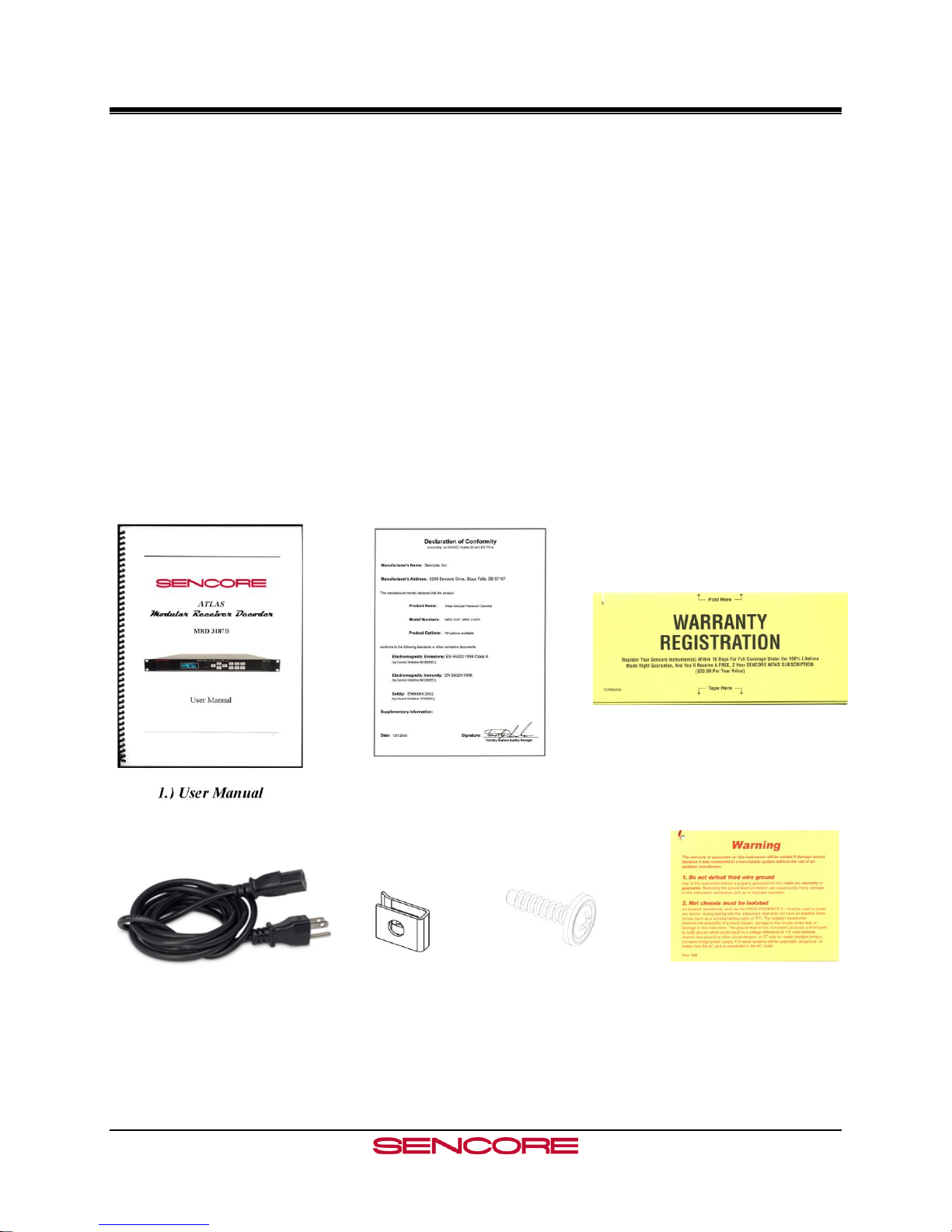
Package Contents
The following is a list of the items that are included along with the MRD 3187B:
1. User Manual
2. Declaration of Conformity
3. Warranty Registration Card
4. AC Power Cable
5. Four (4) Rack Mount Clips
6. Four (4) Rack Mount Screws
7. Third Wire Ground Warning
Note: If any option cables were ordered with the MRD 3187B, they will be included in the box as
well.
If any of these items were omitted from the packaging of the MRD 3187B please call 1-800SENCORE to obtain a replacement.
Page 3
Page 5

MRD 3187B User Manual
How to Use This Manual
Since the MRD 3187B is a modular device, this manual is arranged according to the specific
option cards available. During configuration steps, all button presses are indicated by a picture
of the actual button.
The beginning of each section includes a short description of the section, along with a section
specific table of contents.
When using this manual, many extra pieces of useful information are inserted where pertinent
and are designated in the following forms:
Note
Designator: Note: “ ”
Description: These items are little extra pieces of information to ease unit configuration
Caution
Designator: CAUTION: “ ”
Description: These items should be seriously considered before configuring a setting.
Warning
Designator: Warning: “ ” or WARNING
Description: These items indicate actions that could have severe consequences.
Factory Configurations
The MRD 3187B is an extremely versatile piece of equipment and in order to further expand its
capabilities its internal setup can be factory configured in a number of different ways.
Configuration 1 “Config 1” (No Decoder)
This configuration slaves the internal backplanes to one another but provides no decoded video
output. The placement of input cards can be in both RDS1 and RDS2 (Slots 1-2, 1-3, 1-4, 2-2, 23, 2-4). No video output cards may be installed. This configuration is usually used as a satellite
receiver or in combination with an MPEG/IP card to encapsulate the TS from the active input
and transmit it via IP.
Configuration 1 “Config 1” (Single Decoder)
This configuration slaves the internal backplanes to one another and provides one video output.
The placement of input cards can be in both RDS1 and RDS2 (Slots 1-2, 1-3, 1-4, 2-2, 2-3, 2-4).
Video outputs cards may only be placed in slot 1-1. This configuration allows for the tuning of
two independent audio services. Only one input may be active and only one program decoded at
any time.
Page 4
Page 6

MRD 3187B User Manual
Configuration 1 “Config 1” (Dual Decoder)
This configuration slaves the internal backplanes to one another and provides two mirrored video
outputs. The placement of input cards can be in both RDS1 and RDS2 (Slots 1-2, 1-3, 1-4, 2-2,
2-3, 2-4). Video outputs cards may be placed in slots 1-1 and 2-1. This configuration allows for
the tuning of four independent audio services. This configuration is commonly used to provide
an HD and SD video output from the same input signal. Only one input may be active and only
one program decoded at any time.
Configuration 2 “Config 2” (No Decoder)
This configuration utilizes the internal backplanes independent from one another allowing one
MRD to input two independent inputs simultaneously. With this configuration, the MRD
essentially acts like two configuration 1 no decoder units in the in the rack space of one MRD.
One input per RDS can be active.
Configuration 2 “Config 2” (Single Decoder)
This configuration utilizes the internal backplanes independent from one another. This
configuration operates identical to a configuration 1 unit except for input cards placed in RDS2
(Slots 2-2, 2-3, 2-4) cannot be decoded. A popular use of this configuration is to place an RF
card and an ASI card (i.e. 8701A and 8702) in RDS2 to provide RF input and ASI output to act
as an 8-VSB or satellite receiver. The bottom RDS may then be used independently to decode a
different independent input.
Configuration 2 “Config 2” (Dual Decoder)
This configuration utilizes the internal backplanes independent from one another allowing one
MRD to input and decode two independent inputs simultaneously. With this configuration, the
MRD essentially acts like two configuration 1 single decoder units in the in the rack space of one
decoder. One input per RDS can be active and decode unique video simultaneously.
Page 5
Page 7

MRD 3187B User Manual
Contents
PACKAGE CONTENTS ............................................................................................................................................ 3
HOW TO USE THIS MANUAL ................................................................................................................................ 4
FACTORY CONFIGURATIONS.............................................................................................................................. 4
CONFIGURATION 1 “CONFIG 1” (NO DECODER) ........................................................................................................ 4
CONFIGURATION 1 “CONFIG 1” (SINGLE DECODER) .................................................................................................. 4
CONFIGURATION 1 “CONFIG 1” (DUAL DECODER) .................................................................................................... 5
CONFIGURATION 2 “CONFIG 2” (NO DECODER) ........................................................................................................ 5
CONFIGURATION 2 “CONFIG 2” (SINGLE DECODER) .................................................................................................. 5
CONFIGURATION 2 “CONFIG 2” (DUAL DECODER) .................................................................................................... 5
CONTENTS ................................................................................................................................................................. 6
SECTION 1 – GETTING STARTED ........................................................................................................................ 9
1.1 INSTALLATION ................................................................................................................................................... 10
1.2 QUICK START GUIDE ......................................................................................................................................... 11
1.3 MAINTENANCE .................................................................................................................................................. 11
SECTION 2 – CONTROLS AND CONFIGURATION ......................................................................................... 13
2.1 FRONT OF UNIT ................................................................ ................................................................ .................. 14
2.2 REAR OF UNIT .................................................................................................................................................... 14
2.3 FRONT PANEL DISPLAY LAYOUT ....................................................................................................................... 14
2.4 FRONT PANEL INDICATORS ................................................................................................................................ 14
2.5 INPUT ERROR LOGIC .......................................................................................................................................... 15
2.6 DECODER ERROR LOGIC .................................................................................................................................... 15
2.8 FAN ERROR LOGIC ............................................................................................................................................. 16
2.9 SNMP TRAPS .................................................................................................................................................... 16
2.10 INPUT/OUTPUT SLOT ORGANIZATION .............................................................................................................. 16
SECTION 3 – OPTION CARDS OVERVIEW ...................................................................................................... 17
3.1 LICENSE OPTIONS .............................................................................................................................................. 19
3.2 8VSB/QAM RECEIVER – OPTION 8701A .......................................................................................................... 19
3.3 SERIAL TRANSPORT STREAM I/O (DVB-ASI/SMPTE 310M) – OPTION 8702 ................................................... 19
3.4 HIGH BIT RATE ASI INPUT – OPTION 8703 ........................................................................................................ 19
3.5 VIDEO OUTPUT (2 SD-SDI, 1 COMPOSITE) – OPTION 8704A/8704B ................................................................. 19
3.6 VIDEO OUTPUT (2 HD-SDI, 1 RGBHV/YPBPR) – OPTION 8705/8705A ........................................................... 19
3.7 VIDEO OUTPUT (1 RGBHV/YPBPR, 1 COMPOSITE) – OPTION 8706A ............................................................... 19
3.8 AUDIO OUTPUT (DOLBY E, AES DIGITAL, ANALOG) – OPTION 8707A ............................................................. 20
3.9 VIDEO OUTPUT (2 HD/SH-SDI, 1 RGBHV/YPBPR/COMPOSITE) – OPTION 8708 ............................................. 20
3.10 DUAL INPUT DVB-S/DVB-S2 RECEIVER – OPTION 8710/8710A .................................................................... 20
3.11 DUAL INPUT ASM RECEIVER – OPTION 8711 .................................................................................................. 20
3.12 VIDEO OUTPUT (2 HD/SD-SDI, 1 RGBHV/YPBPR/COMP) – OPTION 8712 .................................................... 20
3.13 GPIO MODULE – OPTION 8713 ........................................................................................................................ 20
3.14 RELAY AND DPI TRIGGER – OPTION 8714 ....................................................................................................... 21
3.15 DUAL INPUT COFDM RECEIVER – OPTION 8715 ............................................................................................ 21
3.16 CAM DECRYPTION – OPTION 8721 ................................................................................................................. 21
3.17 MPEG OVER IP INPUT/OUTPUT – OPTION 8725............................................................................................... 21
3.18 DUAL MPEG OVER IP INPUT/ UDP OUTPUT – OPTION 8727 ........................................................................... 21
SECTION 4 – USING THE FRONT PANEL TO CONFIGURE THE MRD 3187B ......................................... 23
4.1 8VSB/QAM RECEIVER – OPTION 8701A .......................................................................................................... 24
4.2 SERIAL TRANSPORT STREAM INPUT/OUTPUT (DVB-ASI/SMPTE 310M) – OPTION 8702 ................................ 27
Page 6
Page 8

MRD 3187B User Manual
4.3 HIGH BIT RATE ASI INPUT – OPTION 8703 ........................................................................................................ 29
4.4 VIDEO OUTPUT (2 SD-SDI, 1 COMPOSITE) – OPTION 8704A/8704B ................................................................. 31
4.5 VIDEO OUTPUT (2 HD-SDI, 1 RGBHV/YPBPR) – OPTION 8705/8705A ........................................................... 38
4.6 VIDEO OUTPUT (1 RGBHV/YPBPR, 1 COMPOSITE) - OPTION 8706A ................................................................ 44
4.7 AUDIO OUTPUT (DOLBYE, AES DIGITAL, ANALOG) – OPTION 8707A .............................................................. 51
4.8 DUAL VIDEO OUTPUT (2 SDI, 1 RGBHV/YPBPR/COMPOSITE) – OPTION 8708 ................................................ 53
4.9 DUAL INPUT DVB-S/DVB-S2 RECEIVER – OPTION 8710/8710A ...................................................................... 60
4.10 DUAL INPUT ASM RECEIVER – OPTION 8711 .................................................................................................. 64
4.11 VIDEO OUTPUT (2 HD/SD-SDI, 1 RGBHV/YPBPR/COMP) – OPTION 8712 .................................................... 68
4.12 GPIO MODULE – 8713 ..................................................................................................................................... 73
4.13 RELAY AND DPI TRIGGER – OPTION 8714 ....................................................................................................... 75
4.14 DUAL INPUT COFDM RECEIVER – OPTION 8715 ............................................................................................ 78
4.15 CA DECRYPTION – OPTION 8721 ..................................................................................................................... 81
4.16 MPEG OVER IP INPUT/OUTPUT – OPTION 8725............................................................................................... 83
4.17 DUAL MPEG OVER IP INPUT/ UDP OUTPUT – OPTION 8727 ........................................................................... 96
4.18 MPEG-2/MPEG-4 DECODER (1 VIDEO, 2 AUDIO) – OPTION 8730A/8732 .................................................... 109
4.19 MPEG DECODER WITH GENLOCK (1 VIDEO, 4 AUDIO) – OPTION 8733 ......................................................... 118
4.20 MPEG-2/MPEG-4 DECODER WITH GENLOCK (1 VIDEO, 2 AUDIO) – OPTION 8731A/8734 .......................... 127
4.21 NETWORK SETUP ........................................................................................................................................... 136
4.22 SMPTE 333M CONFIGURATION .................................................................................................................... 138
4.23 ACTIVE ERRORS ............................................................................................................................................. 138
4.24 PASSWORD ..................................................................................................................................................... 139
4.25 EVENT LOG .................................................................................................................................................... 140
4.26 SCTE35 TO SCTE104 SETUP ........................................................................................................................ 141
4.27 FEATURE LICENSING ...................................................................................................................................... 143
SECTION 5 – USING THE WEB CLIENT TO CONFIGURE THE MRD 3187B .......................................... 145
5.1 LOGIN .............................................................................................................................................................. 146
5.2 STATUS INDICATORS ........................................................................................................................................ 146
5.3 CONFIGURATION .............................................................................................................................................. 147
5.4 UNIT ................................................................................................................................................................ 154
5.5 PROFILES ......................................................................................................................................................... 156
5.6 WEB PASSWORDS ............................................................................................................................................ 159
5.7 RESET UNIT ..................................................................................................................................................... 159
5.8 SNMP MIB MODULES .................................................................................................................................... 160
5.9 SOFTWARE UPDATES ................................................................ ................................ ....................................... 160
5.10 DIAGNOSTICS ................................................................................................................................................. 160
5.11 ABOUT ........................................................................................................................................................... 161
SECTION 6 – USING SIMPLE NETWORK MANAGEMENT PROTOCOL (SNMP) TO CONFIGURE
THE MRD 3187B..................................................................................................................................................... 163
6.1 SNMP CONFIGURATION .................................................................................................................................. 164
APPENDICES .......................................................................................................................................................... 167
APPENDIX A – ACRONYMS AND GLOSSARY ................................................................ .......................................... 168
APPENDIX B – ERROR LIST .................................................................................................................................... 171
APPENDIX C – SPECIFICATIONS ............................................................................................................................. 173
APPENDIX D – PINOUT OF 8705/8705A, 8708 AND 8707A .................................................................................... 196
APPENDIX E – COORDINATED UNIVERSAL TIME ................................................................................................... 197
APPENDIX F – OPEN SOURCE SOFTWARE .............................................................................................................. 198
APPENDIX G – WARRANTY .................................................................................................................................... 199
APPENDIX H – SUPPORT AND CONTACT INFORMATION ................................................................ ......................... 200
Page 7
Page 9

MRD 3187B User Manual
This Page Intentionally Left Blank
Page 8
Page 10
MRD 3187B User Manual
Section 1 – Getting Started
Introduction
This section includes the following topics:
1.1 INSTALLATION ................................................................................................................................................... 10
1.2 QUICK START GUIDE ......................................................................................................................................... 11
1.3 MAINTENANCE .................................................................................................................................................. 11
Page 9
Page 11
MRD 3187B User Manual
1.1 Installation
Cooling
The MRD 3187B is cooled via forced induction through the front of the unit and exhausted
through the vents on either side. The MRD 3187B is equipped with a temperature controlled
status indicator. If the temperature in the inside of the unit exceeds 70° C the red “Error”
LED will illuminate and a description of the error will appear in the “Error List.”
Rack Information
The MRD 3187B is intended to be mounted in a standard 19” rack. It occupies 1U of rack
space and the connections are all on the rear of the unit.
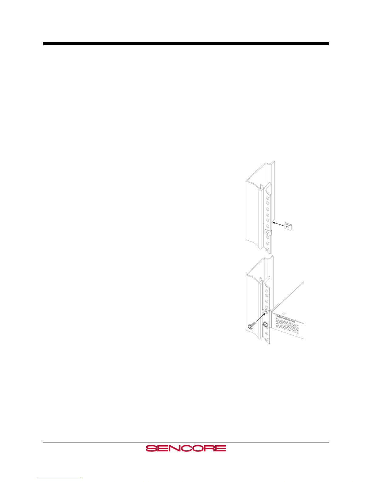
Rack Installation
To install the MRD 3187B into a rack use the
following steps:
1. Determine the desired position in the rack for the
MRD 3187B making sure that the air intake on
the front of the unit and the exhausts on the sides
of the unit will not be obstructed.
2. Insert the rack mount clips into place over the
mounting holes in the rack.
3. Slide the MRD 3187B into position in the rack.
4. Secure the MRD 3187B to the rack by installing
the four supplied screws through the front
mounting holes and tightening.
Power Connection
Using the proper power connections is vital to the safe operation of the MRD 3187B. Only
use the supplied 3-prong power connector or one with equal specifications. NEVER tamper
with or remove the 3rd – prong grounding pin. This could cause damage to the MRD 3187B,
personnel, or property.
Page 10
Page 12

MRD 3187B User Manual
AC Power Connection
The MRD 3187B is intended for use on either 120V or 240V systems. The power supply
will automatically detect the system it is connected to. To hook up the power use the
following steps:
1. Locate the AC power cord that was included with the MRD 3187B.
2. Plug the female end of the power cord (end with no prongs) into the back of the unit.
3. Locate a protected outlet (usually inside of the rack) to plug the male end of the power
cable into.
DC Power Connection (if equipped)
Using the proper power connections is vital to the safe operation of the MRD 3187B. The
MRD 3187B is intended for use in 40-65Vdc systems. The power supply will automatically
detect the system it is connected to. When installing the MRD 3187B, the power supply
MUST be used in conjunction with an over-current protective device rated at 50V, 5A,
type: Slow-blo, as part of battery-supply circuit. Failure to include an over-current
protective device could cause damage to the MRD 3187B, personnel, or property.
1.2 Quick Start Guide
Quick Start
To get the MRD 3187B up and running there is a few things that need to be done.
1. Select the desired input as active.
2. Setup the decoder with the proper PIDs.
3. Setup the desired output(s).
The easiest way to set these options up is to refer to Section 4. At the beginning of Section 4
is a table that shows the specific cards included in that section. Find the desired card in the
table, then navigate to the corresponding page number and follow the step-by-step
instructions.
1.3 Maintenance
The MRD 3187B is virtually a maintenance-free piece of equipment. There are no user
serviceable parts on the inside of the unit however it is recommended that the user cleans the
intake filter on the front right side of the unit on a regular basis to ensure the unit has an
unobstructed cool air intake. This filter is removed easily, for cleaning, by opening the door
on the front right side of the unit and removing the filter.
Page 11
Page 13

MRD 3187B User Manual
This Page Intentionally Left Blank
Page 12
Page 14
MRD 3187B User Manual
Section 2 – Controls and Configuration
Introduction
This section includes an overview of the MRD 3187B.
2.1 FRONT OF UNIT .................................................................................................................................................. 14
2.2 REAR OF UNIT .................................................................................................................................................... 14
2.3 FRONT PANEL DISPLAY LAYOUT ....................................................................................................................... 14
2.4 FRONT PANEL INDICATORS ................................................................................................................................ 14
2.5 INPUT ERROR LOGIC .......................................................................................................................................... 15
2.6 DECODER ERROR LOGIC .................................................................................................................................... 15
2.8 FAN ERROR LOGIC ............................................................................................................................................. 16
2.9 SNMP TRAPS .................................................................................................................................................... 16
2.10 INPUT/OUTPUT SLOT ORGANIZATION .............................................................................................................. 16
Page 13
Page 15
MRD 3187B User Manual
RDS1 Serv Setup
Tune Mode:PID Lock
PID Select:Manual
►PCR PID :0x0031
1 3 1
4
2
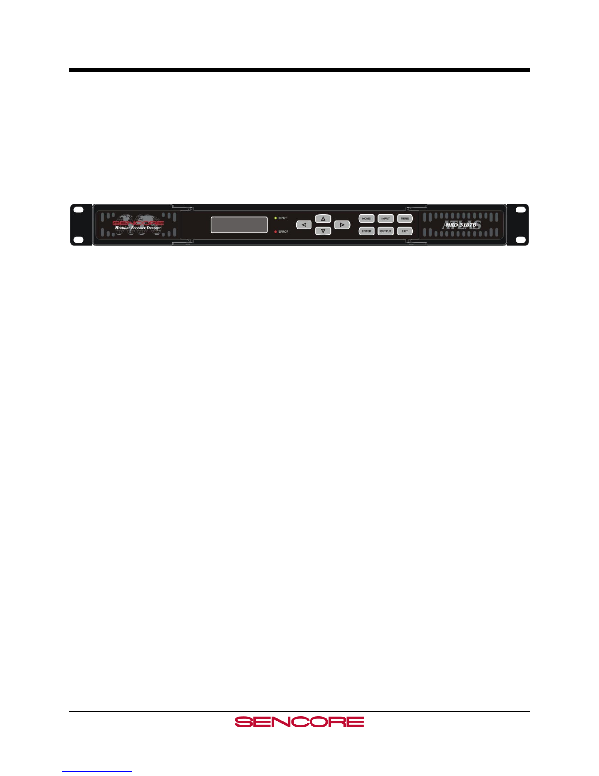
2.1 Front of Unit
2.2 Rear of Unit
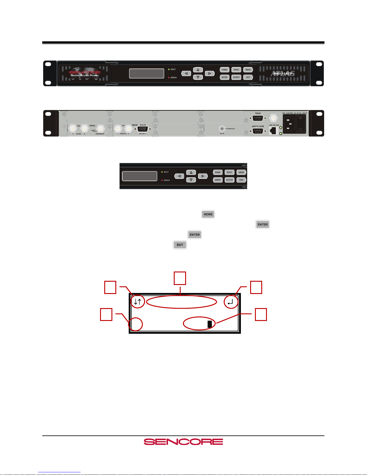
2.3 Front Panel Display Layout
The following figure shows a typical screen on the front panel. Several important features have
been circled and noted below. These features are common to all screens and assist when
navigating, viewing and editing unit information. The button will return the user to the
home level while in any screen. In order to edit a selected parameter, the button must be
pressed. Once a parameter has been changed, the button must be pressed again before the
change takes effect on the unit. Pressing the button will leave an edit mode without
changes taking effect.
1. Icons indicate which control buttons are currently valid for entry.
2. Screen title.
3. Cursor shows which line is active.
4. When editing, active character or item is highlighted.
2.4 Front Panel Indicators
The MRD 3187B has four internal error parameters: INPUT, DECODER, FAN and
TEMPERATURE. These parameters can be monitored locally or remotely. Locally the unit’s
status can be checked by visually looking at the INPUT LED and the ERROR LED on the front
Page 14
Page 16

MRD 3187B User Manual
panel, then use the “Error List” under the button to pinpoint the error. Remotely, the unit’s
status can be checked by using the web client and looking at the status icons on the top of the
main window. To see a detailed list of errors, click on the tab from the web client.
The INPUT LED indicates the presence of a stream at the user-selected
input. “Stream present” is represented by a green INPUT LED while
“stream NOT present” is represented by a dark INPUT LED.
The ERROR LED represents the combined status of the unit’s error
indicators. If INPUT, DECODER, TEMP, or FAN status is in the error
state, the LED will be red. If all error indicators are good, the LED will be
dark.
2.5 Input Error Logic
The input status is based on the selected input card’s status and the transport error indicator bit
in the transport stream being decoded. For example if the current input is VSB, the input status
is based on: VSB receiver lock, RF channel level, and the MER level. The RF channel and
MER thresholds can be set by the user. If the unit detects the presence of the transport error bit
in a transport packet header, the input status will be an error for 0.5 seconds each time the TS
error bit is set. The system must detect a constant cadence of sync bytes (0x47h) every 188
bytes and detect a valid PAT at least every 500 ms in order for the INPUT LED to illuminate.
2.6 Decoder Error Logic
The decoder error indicator is based on the decoder’s ability to decode what the user has
requested. The input status will be alarmed differently depending on the current decoding mode:
In “Auto Mode,” the decoder status will be good unless the Video or Audio decoders cannot
decode a stream. For example: a stream defines program 4 to have video on PID 52. If PID
52 is not actually present in the stream, or is un-decodable, the decoder status will be in the
error state. This is true for all modes.
In “PID Lock Mode,” the decoder status will be good if all of the PIDs entered by the user,
for video and audio, are being decoded by the unit. If the user wants nothing to be decoded,
they can set a PID to 0. If the user enters a PID which is not present or cannot be decoded
the decoder status will be in the error state.
In “Program Priority Mode,” the decoder status will be good if any priority is currently active
and the Audio and Video represented by that priority are being decoded. If the PMT for a
selected program lists a video or audio PID, but the decoder cannot decode that PID, the
indicator will be in the error state. If the user enters an index for a priority that does not exist
in the PMT, the indicator will still be good because the decoder will be set to decode nothing
on that audio output.2.7 Temperature Error Logic
The temperature error indicator is based on the correct operation of the unit. If the unit’s
temperature exceeds 70 degrees C, the temperature status will be in the error state.
Page 15
Page 17
MRD 3187B User Manual
2.8 Fan Error Logic
If the fan in the unit fails, the fan status will be in the error state. The fan status will be good as
long as the fan is spinning at the proper RPM.
2.9 SNMP Traps
The unit contains separate SNMP Traps for Fan Status, Temperature Status, Decoder Status,
Input Status, and IP Receive Group. Whenever any item changes state, a trap is sent to the
configured host.
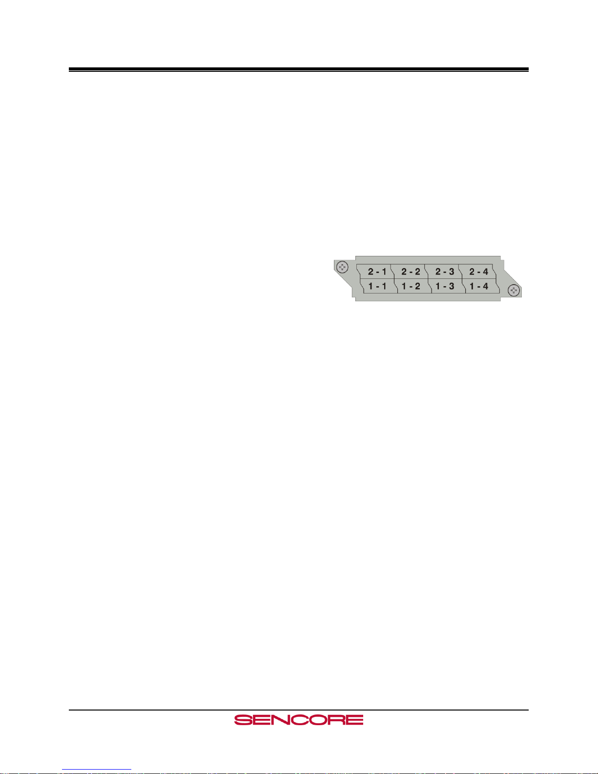
2.10 Input/Output Slot Organization
The MRD 3187B’s modular design allows many different input/output configurations. An
indexing system is used to identify module slots for
configuration and monitoring reference. The bottom
row of slots is numbered 1-1 through 1-4 (left to
right). The top row is numbered 2-1 through 2-4 as
shown.
Page 16
Page 18

MRD 3187B User Manual
Section 3 – Option Cards Overview
Introduction
This section includes a brief overview of the different option cards that are available for
the MRD 3187B. There are descriptions of each card as well as pictures of the various
inputs and outputs for each card.
3.1 LICENSE OPTIONS .............................................................................................................................................. 19
3.2 8VSB/QAM RECEIVER – OPTION 8701A .......................................................................................................... 19
3.3 SERIAL TRANSPORT STREAM I/O (DVB-ASI/SMPTE 310M) – OPTION 8702 ................................................... 19
3.4 HIGH BIT RATE ASI INPUT – OPTION 8703 ........................................................................................................ 19
3.5 VIDEO OUTPUT (2 SD-SDI, 1 COMPOSITE) – OPTION 8704A/8704B ................................................................. 19
3.6 VIDEO OUTPUT (2 HD-SDI, 1 RGBHV/YPBPR) – OPTION 8705/8705A ........................................................... 19
3.7 VIDEO OUTPUT (1 RGBHV/YPBPR, 1 COMPOSITE) – OPTION 8706A ............................................................... 19
3.8 AUDIO OUTPUT (DOLBY E, AES DIGITAL, ANALOG) – OPTION 8707A ............................................................. 20
3.9 VIDEO OUTPUT (2 HD/SH-SDI, 1 RGBHV/YPBPR/COMPOSITE) – OPTION 8708 ............................................. 20
3.10 DUAL INPUT DVB-S/DVB-S2 RECEIVER – OPTION 8710/8710A .................................................................... 20
3.11 DUAL INPUT ASM RECEIVER – OPTION 8711 .................................................................................................. 20
3.12 VIDEO OUTPUT (2 HD/SD-SDI, 1 RGBHV/YPBPR/COMP) – OPTION 8712 .................................................... 20
3.13 GPIO MODULE – OPTION 8713 ........................................................................................................................ 20
3.14 RELAY AND DPI TRIGGER – OPTION 8714 ....................................................................................................... 21
3.15 DUAL INPUT COFDM RECEIVER – OPTION 8715 ............................................................................................ 21
3.16 CAM DECRYPTION – OPTION 8721 ................................................................................................................. 21
3.17 MPEG OVER IP INPUT/OUTPUT – OPTION 8725............................................................................................... 21
3.18 DUAL MPEG OVER IP INPUT/ UDP OUTPUT – OPTION 8727 ........................................................................... 21
Page 17
Page 19

MRD 3187B User Manual
Page 18
Page 20

MRD 3187B User Manual
3.1 License Options
The MRD 3187B has two license options available. A separate license must be purchased to (1)
decode MPEG4 or H.264 and/or (2) convert SCTE35 to SCTE104.
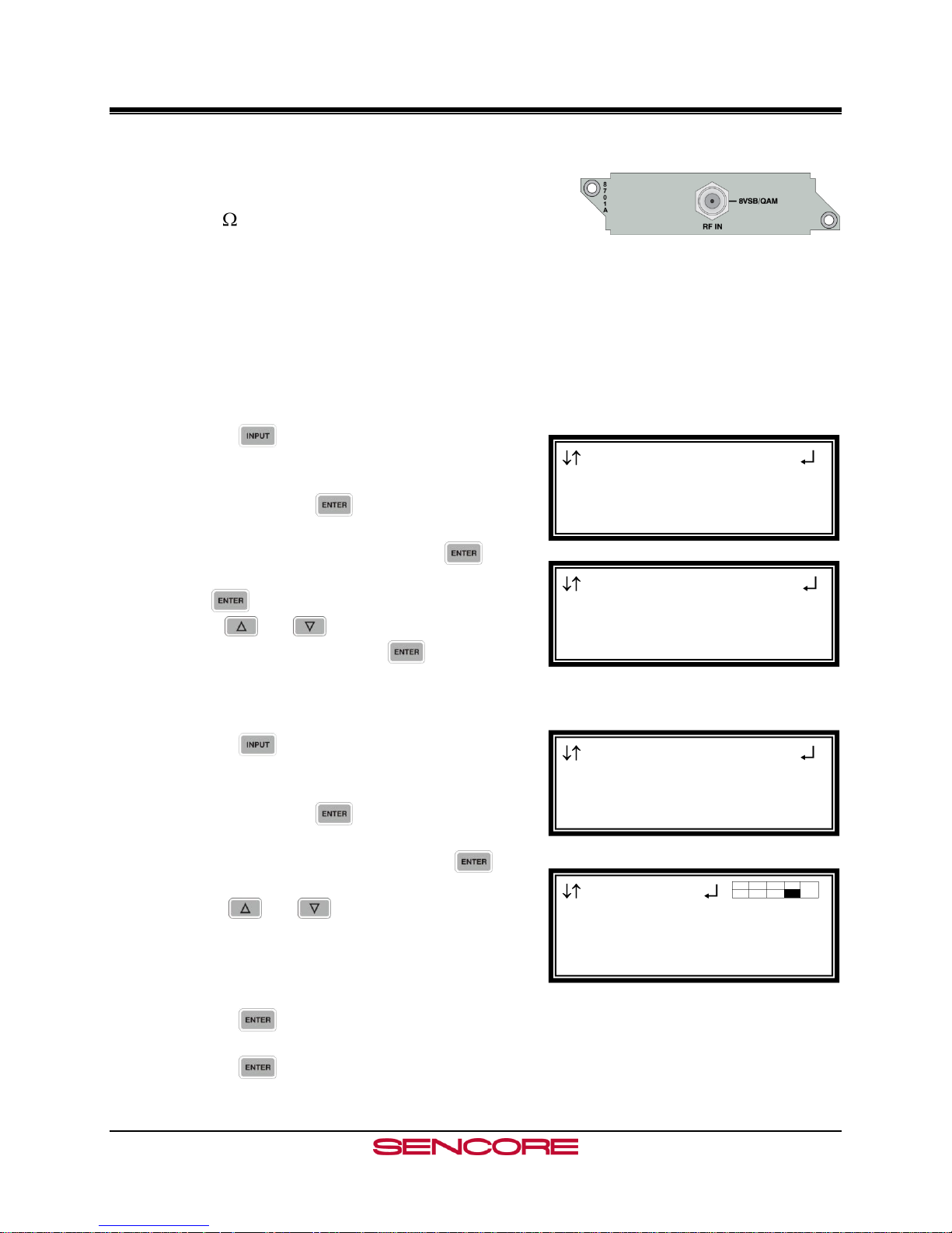
3.2 8VSB/QAM Receiver – Option 8701A
This card will receive a TS that is demodulated from an 8VSB signal or it will demodulate a
QAM64B or QAM256B RF input. With an 8VSB input, the card will tune to channels 2 – 69.
With a QAM input, the card will tune to channels 2 – 134 in three cable frequency bands (FCC,
IRC, and HRC). The MRD 3187B will show a valid input if the following conditions are met:
the receiver equalizer and the FEC are locked. If the RF level is lower than the “Low Warning
Setting” or the MER is lower than the “Low MER Warning Setting,” the red “Error” LED will
illuminate on the front panel and there will be an error recorded in the Error List.
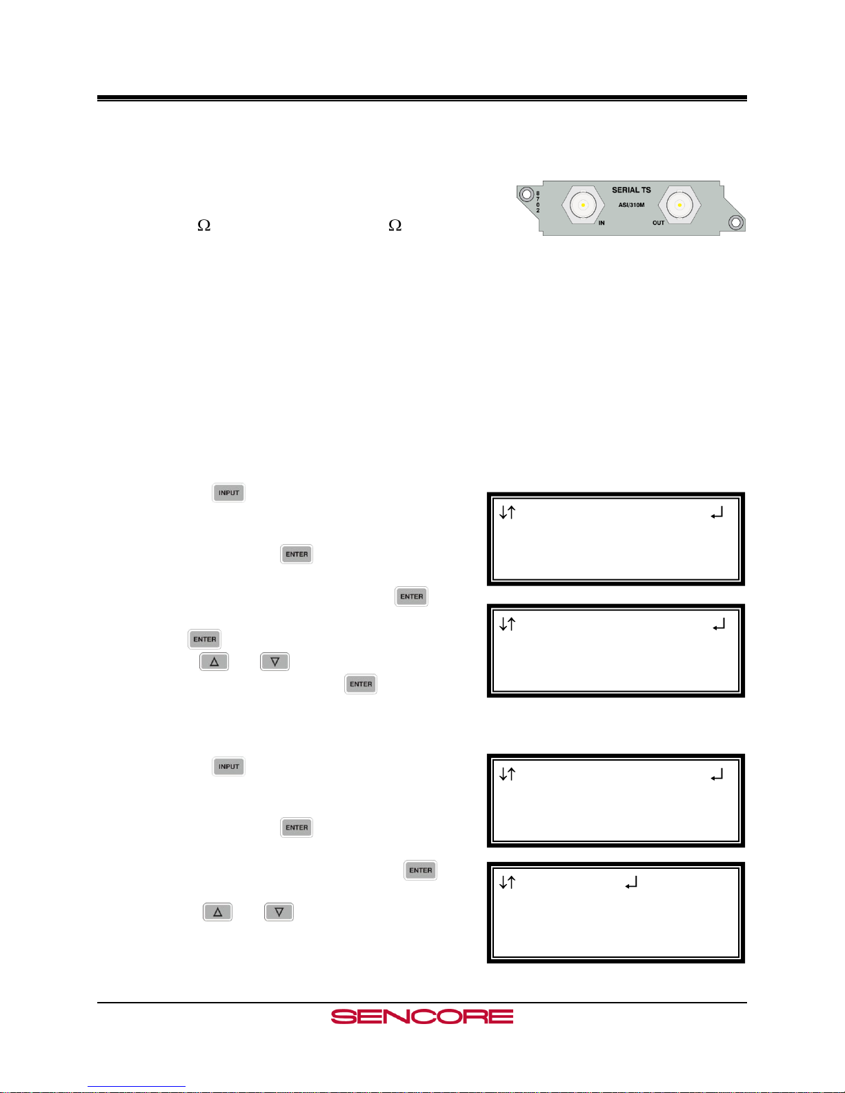
3.3 Serial Transport Stream I/O (DVB-ASI/SMPTE 310M) – Option 8702
This card will receive a TS from either a DVB-ASI input or a SMPTE 310M input. Only one
format may be selected at a time. For an ASI input, the bitrate of the TS must be between
1.5Mb/s and 160Mb/s. For a SMPTE 310M input, the bitrate of the TS must be 19.392658Mb/s.
The selected input format will also be the output format. The 8702 card can also be used as a TS
output for any of the other input cards.
3.4 High Bit Rate ASI Input – Option 8703
This card will receive, up to a 160Mb/s MPTS on ASI. This card is equipped with a passive
loop-through to allow the TS to be passed through the card without altering the stream. The
loop-through on this card cannot be used to output a TS from a different input card. When the
loop-through output is not in use it should be terminated with a 75 Ohm terminator.
3.5 Video Output (2 SD-SDI, 1 Composite) – Option 8704A/8704B
A standard definition video output card. It provides two mirrored serial digital (SMPTE 259M)
outputs and one composite NTSC & PAL output. Four pairs of audio can be embedded into the
serial output on group 1 and 2. Closed captioning found within the transport (608/708B) can be
embedded into the serial video output. NTSC closed caption, detected in the transport stream,
can be inserted on line 21.
3.6 Video Output (2 HD-SDI, 1 RGBHV/YPbPr) – Option 8705/8705A
A high definition video output card. It provides two mirrored serial digital (SMPTE 292M)
outputs and one analog component video output (RGBHV or YPbPr). Four pairs of audio can be
embedded into the serial output on group 1 and 2. Closed captioning found within the transport
(608/708B) can be embedded into the serial video output.
3.7 Video Output (1 RGBHV/YPbPr, 1 Composite) – Option 8706A
An analog only video output card that can output either high definition or standard definition
formats. Two outputs are on the card: one BNC for composite (NTSC & PAL) and one 15-pin
D-sub for component (RGBHV or YPbPr). The card outputs an SD or HD signal, one at a time.
Closed caption (NTSC), detected in the transport stream, can be inserted on line 21 of the
composite (NTSC video) output.
Page 19
Page 21

MRD 3187B User Manual
3.8 Audio Output (Dolby E, AES Digital, Analog) – Option 8707A
This card allows the output of both Digital-AES and analog audio. Each digital audio output can
be set to either Raw or PCM. In Raw, the compressed audio for the selected PID is passed
through to the digital output. Typically this setting is used to pass-through the Dolby AC-3
compressed digital signal. When the digital audio output is set to PCM, two-channel linear coded
PCM AES/EBU audio is output to the digital output. The analog output provides two-channel (L,
R) decoded analog audio from the selected audio processor. The two audio processors on the
decoder board, feeding the two digital outputs, can process or decode Dolby AC-3, MPEG Layer
1, or MPEG Layer 2 formats. The audio processor will self-sense which type of audio is in the
TS. The 8707A also has a Dolby E parsing feature.
3.9 Video Output (2 HD/SH-SDI, 1 RGBHV/YPbPr/Composite) – Option 8708
A versatile video output card. It provides two user selectable serial digital (SMPTE 259M, or
SMPTE 292M) outputs and one component RGBHV or YPbPr/Composite NTSC & PAL output.
Four pairs of audio can be embedded into the serial output on group 1, and 2. Closed captioning
found within the transport (608/708B) can be embedded into the serial video output. NTSC
closed caption, detected in the transport stream, can be inserted on line 21.
3.10 Dual Input DVB-S/DVB-S2 Receiver – Option 8710/8710A
This card will input a satellite L-band (950MHz – 2150MHz) signal for demodulation of KUband or C-band DVB-S QPSK signals or DVB-S2 QPSK/8PSK signals. The symbol rate ranges
from 1MSym/s to 45MSym/s for DVB-S and 1-30MSym/s for DVB-S2. This card does not
provide any power to the dish LNB. The “Input” LED will only illuminate if the card detects
frequency, symbol rate, FEC lock (Carrier Lock), and TS sync (Sync Lock). The card provides
A and B inputs, which may be independently configured, but only one may be active at a time.
3.11 Dual Input ASM Receiver – Option 8711
This card will input a satellite L-band (950MHz – 2150MHz) signal for demodulation of KUband, C-band, or X-band DVB-QPSK, 8PSK, or Adv-QPSK signals. All these modes are
available using Turbo Coded forward error correction. The DVB-QPSK mode also supports
legacy DVB FEC. The symbol rate ranges from 0.256MSym/s to 30MSym/s for all modulation
types. This card does not provide any power to the dish LNB. The “Input” LED will only
illuminate if the card detects frequency, symbol rate, FEC lock (Carrier Lock), and TS sync
(Sync Lock). The card provides A and B inputs, which may be independently configured, but
only one may be active at a time.
3.12 Video Output (2 HD/SD-SDI, 1 RGBHV/YPbPr/Comp) – Option 8712
A versatile video output card. It provides two user selectable serial digital (SMPTE 259M, or
SMPTE 292M) outputs and one component RGBHV or YPbPr/Composite NTSC & PAL output.
Eight pairs of audio can be embedded into the serial output on group 1, 2, 3 and 4. Closed
captioning found within the transport (608/708B) can be embedded into the serial video output.
NTSC closed caption, detected in the transport stream, can be inserted on line 21.
Note: This card requires the 8733 decoder board.
3.13 GPIO Module – Option 8713
Page 20
Page 22

MRD 3187B User Manual
This module is considered a global unit option. In other words, the inputs and outputs of a single
installed module can be accessed by functions associated with general system features, or RDS
specific features in any unit configuration. Only one GPIO module can be installed in a unit.
3.14 Relay and DPI Trigger – Option 8714
This card is a single-slot module and should be considered a global unit option. In other words,
the relays of a single installed module can be accessed by functions associated with general
system alarms, or RDS specific features in any unit configuration.
3.15 Dual Input COFDM Receiver – Option 8715
This card will input a (49 – 861 MHz) COFDM signal for use in electronic news gathering (U.S.)
or any COFDM Terrestrial Broadcast (DVB-T, European) applications. The card provides A
and B inputs, which may be independently configured, but only one may be active at a time.
3.16 CAM Decryption – Option 8721
This is a factory installed slot that will allow for up to two CAM cards to be installed at a time,
giving the MRD 3187B the ability to decrypt Conditional Access transport streams. This card
also includes all the functionality of the 8722 option card as well.
3.17 MPEG over IP Input/Output – Option 8725
This card is a dual purpose card in that it can receive and/or transmit from the internal TS bus,
MPEG over IP. Up to two multicasts can be subscribed to, allowing for a backup multicast to be
chosen and three mirrored multicasts can be transmitted to allow for redundancy.
3.18 Dual MPEG over IP Input/ UDP Output – Option 8727
This card is a dual purpose card in that it can receive and/or transmit from the internal TS bus,
MPEG over IP. It has two physical connectors that can be configured independently. Up to two
multicasts can be subscribed to, allowing for a backup multicast to be chosen and two UDP
mirrored unicasts can be transmitted to allow for redundancy
Example Configurations: IP Address Selection
“Leave” IGMP V2 & V3 Multicast/Unicast Unicast: X.X.X.X – 223.255.255.255
Filter Mode: Include Multicast: 224.X.X.X – 239.255.255.255
IP list: empty Suggested Multicast Range: 239.192.X.X
“Join” IGMP V2 & V3 Multicast/Unicast Suggested Port Selection
Filter Mode: Exclude - Choose a port number of 5000 or more
IP list: empty - Choose even numbered ports
- If using FEC the following example applies
“Join Filtered” IGMP V3 Multicast/Unicast - Destination port = 5000
Filter Mode: Include - Column FEC = 5002
IP: X.X.X.X - Row REC = 5004
Or - Next available multicast port = 5006
Filter Mode: Exclude
IP: X.X.X.X
Page 21
Page 23

MRD 3187B User Manual
This Page Intentionally Left Blank
Page 22
Page 24
MRD 3187B User Manual
Section 4 – Using the Front Panel to
Configure the MRD 3187B
Introduction
This section describes how to navigate through the configuration menus on the front
panel of the MRD 3187B.
Note: All instructions in this manual are based on the unit software versions 7.2.X. Newer
versions of software, when released, may operate slightly different in regards to menus
and configuration.
4.1 8VSB/QAM RECEIVER – OPTION 8701A .......................................................................................................... 24
4.2 SERIAL TRANSPORT STREAM INPUT/OUTPUT (DVB-ASI/SMPTE 310M) – OPTION 8702 ................................ 27
4.3 HIGH BIT RATE ASI INPUT – OPTION 8703 ........................................................................................................ 29
4.4 VIDEO OUTPUT (2 SD-SDI, 1 COMPOSITE) – OPTION 8704A/8704B ................................................................. 31
4.5 VIDEO OUTPUT (2 HD-SDI, 1 RGBHV/YPBPR) – OPTION 8705/8705A ........................................................... 38
4.6 VIDEO OUTPUT (1 RGBHV/YPBPR, 1 COMPOSITE) - OPTION 8706A ................................................................ 44
4.7 AUDIO OUTPUT (DOLBYE, AES DIGITAL, ANALOG) – OPTION 8707A .............................................................. 51
4.8 DUAL VIDEO OUTPUT (2 SDI, 1 RGBHV/YPBPR/COMPOSITE) – OPTION 8708 ................................................ 53
4.9 DUAL INPUT DVB-S/DVB-S2 RECEIVER – OPTION 8710/8710A ...................................................................... 60
4.10 DUAL INPUT ASM RECEIVER – OPTION 8711 .................................................................................................. 64
4.11 VIDEO OUTPUT (2 HD/SD-SDI, 1 RGBHV/YPBPR/COMP) – OPTION 8712 .................................................... 68
4.12 GPIO MODULE – 8713 ..................................................................................................................................... 73
4.13 RELAY AND DPI TRIGGER – OPTION 8714 ....................................................................................................... 75
4.14 DUAL INPUT COFDM RECEIVER – OPTION 8715 ............................................................................................ 78
4.15 CA DECRYPTION – OPTION 8721 ..................................................................................................................... 81
4.16 MPEG OVER IP INPUT/OUTPUT – OPTION 8725............................................................................................... 83
4.17 DUAL MPEG OVER IP INPUT/ UDP OUTPUT – OPTION 8727 ........................................................................... 96
4.18 MPEG-2/MPEG-4 DECODER (1 VIDEO, 2 AUDIO) – OPTION 8730A/8732 .................................................... 109
4.19 MPEG DECODER WITH GENLOCK (1 VIDEO, 4 AUDIO) – OPTION 8733 ......................................................... 118
4.20 MPEG-2/MPEG-4 DECODER WITH GENLOCK (1 VIDEO, 2 AUDIO) – OPTION 8731A/8734 .......................... 127
4.21 NETWORK SETUP ........................................................................................................................................... 136
4.22 SMPTE 333M CONFIGURATION .................................................................................................................... 138
4.23 ACTIVE ERRORS ............................................................................................................................................. 138
4.24 PASSWORD ..................................................................................................................................................... 139
4.25 EVENT LOG .................................................................................................................................................... 140
4.26 SCTE35 TO SCTE104 SETUP ........................................................................................................................ 141
4.27 FEATURE LICENSING ...................................................................................................................................... 143
Page 23
Page 25
MRD 3187B User Manual
Input
►Active Input
Backup Mode
Input Modules
Active Input
Active Input:
► VSB/QAM 1-4
Input
Active Input
Backup Mode
►Input Modules
Input
ASI+ 1-3
►VSB/QAM 1-4
ASI/310M 2-3
4.1 8VSB/QAM Receiver – Option 8701A
General Information
Install Location: Any slot except 1-1 and 2-1.
I/O: (1) 75 Female F Connector
Supported Formats: 8VSB, QAM64B, QAM256B
Description: This card provides demodulation of 8VSB or QAM. For 8VSB the card is able
to tune to channels 2-69 on UHF/VHF and channels 2-134 on the cable channel bands of
FCC cable, IRC, and HRC. For QAM, the card is able to receive both QAM64B and
QAM256B and is able to tune to channels 2-134 in the cable bands of FCC cable, IRC,
and HRC.
Input Control
To enable this card as an input use the following steps.
1. Press the button.
Note: For Configuration 2 units, select RDS1 or
RDS2, then press .
2. Select “Active Input”, then press the
button.
3. Press twice to change the active input and
use the and buttons to select the input
to make active, and press the button to save
the changes.
Configure Input
1. Press the button.
Note: For Configuration 2 units, select RDS1 or
RDS2, then press .
2. Select “Input Modules”, and press the
button.
3. Use the and buttons to move the cursor
to the “VSB/QAM” card of the specific slot (e.g.
1-4). Notice the location diagram in the upper
right corner of the screen changes as the cursor
moves by each card.
4. Press the button once to display the Status
screen for the VSB/QAM card.
5. Press the button again to display the Edit
screen for the VSB/QAM card.
Page 24
Page 26
MRD 3187B User Manual
VSB/QAM 1-4
►Selected I/O:no
Chan:__
Modulation:8VSB
VSB/QAM 1-4
Selected I/O:yes
►Chan:32
Modulation:8VSB
VSB/QAM 1-4
Modulation:8VSB
Air/CATV:OffAir
►Low:+00dBmV
VSB/QAM 1-4
Selected I/O:yes
Chan:32
►Modulation:8VSB
VSB/QAM 1-4
Modulation:8VSB
►Air/CATV:OffAir
Low:+00dBmV
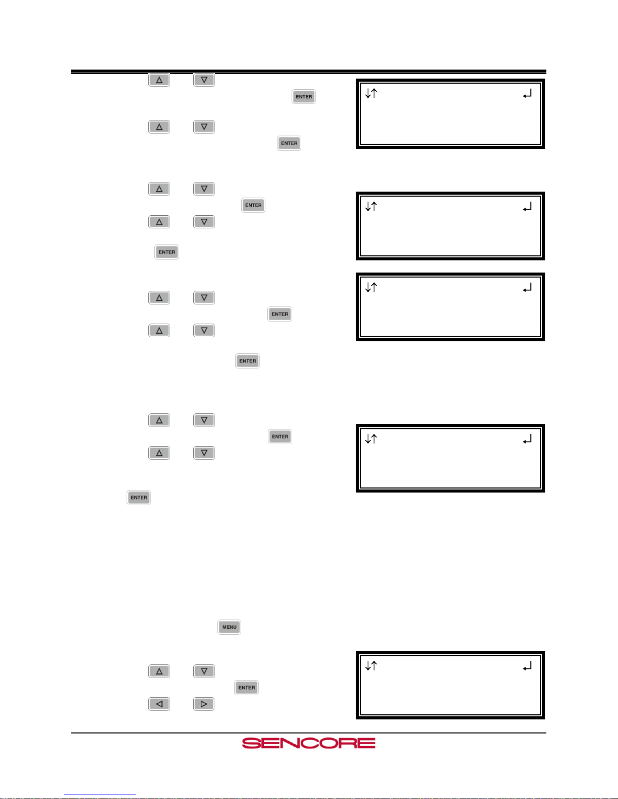
6. Use the and buttons to move the cursor
to “Selected I/O:” then press the
button.
7. Use the and buttons to change the
selection to, “yes,” then press the button.
Channel
1. Use the and buttons to move the cursor
to, “Chan:” then press the button.
2. Use the and buttons to tune to the
specific RF channel of interest (2-134), then
press the button to save the selection.
Modulation
1. Use the and buttons to move the cursor
to, “Modulation:” then press the button.
2. Use the and buttons to choose the
appropriate modulation type (8VSB, QAM64B,
QAM256B), then press the button to save the
selection.
Channel Bands
1. Use the and buttons to move the cursor
to, “Air/CATV:” then press the button.
2. Use the and buttons to choose the
appropriate channel band (OffAir, Cable-
FCC, Cable-HRC, Cable-IRC), then press
the button to save the selection.
Set Low Signal and MER Error Levels
These two values are user defined threshold levels for
the signal level and MER level. Once these values are
set, if the input levels drops below the defined value,
an error will be triggered which will cause the red
“Error” LED to illuminate on the front panel, a
description of the error will be shown in the “Active
Errors” menu under the button, and an entry
will be logged in the event log.
1. Use the and buttons to move the cursor
to, “Low:” then press the button.
2. Use the and buttons to select the
Page 25
Page 27
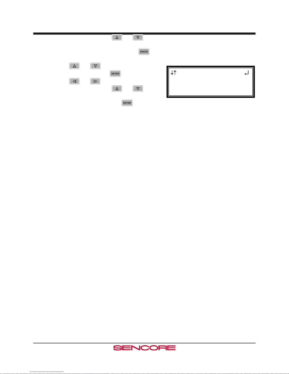
MRD 3187B User Manual
VSB/QAM 1-4
Air/CATV:OffAir
Low:+00dBmV
►MER:10dB
column to edit and use the and buttons to
set the value of the low signal alarm threshold (-
30dBmV - +40dBmV), then press the button
to save the selection.
3. Use the and buttons to move the cursor
to, “MER:” then press the button.
4. Use the and buttons to select the
column to edit and use the and buttons
to set the value of the low MER alarm threshold
(0dB – 40dB), then press the button to save
the selection.
Page 26
Page 28
MRD 3187B User Manual
Input
►Active Input
Backup Mode
Input Modules
Active Input
Active Input:
► ASI/310M 2-3
Input
Active Input
Backup Mode
►Input Modules
Input
ASI+ 1-3
VSB/QAM 1-4
►ASI/310M 2-3
4.2 Serial Transport Stream Input/Output (DVB-ASI/SMPTE 310M) –
Option 8702
General Information
Install Location: Any slot except 1-1 and 2-1.
I/O: (1) 75 Female BNC Input, (1) 75 Female BNC
Output
Supported Formats: DVB-ASI, 310M
Description: This card provides either DVB-ASI or 310M input and output. The card will
provide 310M output only if the input TS is 19.39Mb/sec. When the card is in ASI
mode, the TS bitrate for both the input and output is from 1.5Mb/sec – 160Mb/sec.
When the card is in SMPTE 310M mode, the bitrate for both input and output must be
19.39Mb/sec. The output jack on this card is an active loop-through (i.e. a re-serialized
TS). The output will be the same type that the input is set for (e.g. 310M or ASI). The
card can be used to provide an ASI TS output from another type of input on the unit
(e.g. 8VSB).
Input Control
To enable this card as an input use the following steps.
1. Press the button.
Note: For Configuration 2 units, select RDS1 or
RDS2, then press .
2. Select “Active Input”, then press the
button.
3. Press twice to change the active input and
use the and buttons to select the input
to make active, and press the button to save
the changes.
Configure Input
1. Press the button.
Note: For Configuration 2 units, select RDS1 or
RDS2, then press .
2. Select “Input Modules”, and press the
button.
3. Use the and buttons to move the cursor
to the “ASI/310M” card of the specific slot (e.g.
2-3). Notice the location diagram in the upper
right corner of the screen changes as the cursor
Page 27
Page 29
MRD 3187B User Manual
ASI/310M 2-3
►Selected I/O:no
Type:ASI
ASI/310M 2-3
Selected I/O:yes
►Type:ASI
moves by each card.
4. Press the button once to display the Status
screen for the ASI/310M card.
5. Press the button again to display the Edit
screen for the ASI/310M card.
6. Use the and buttons to move the cursor
to, “Selected I/O:” then press the
button.
7. Use the and buttons to change the selection to, “yes,” then press the
button.
Input Type
1. Use the and buttons to move the cursor
to, “Type:” then press the button.
2. Use the and buttons to select the
appropriate input (ASI, 310M), then press the
button to save the selection.
Page 28
Page 30
MRD 3187B User Manual
Input
►ASI+ 2-2
VSB/QAM 1-4
ASI/310M 2-3
ASI+ 2-2
►Selected I/O:no
Input
►Active Input
Backup Mode
Input Modules
Active Input
Active Input:
► ASI+ 2-2
Input
Active Input
Backup Mode
►Input Modules
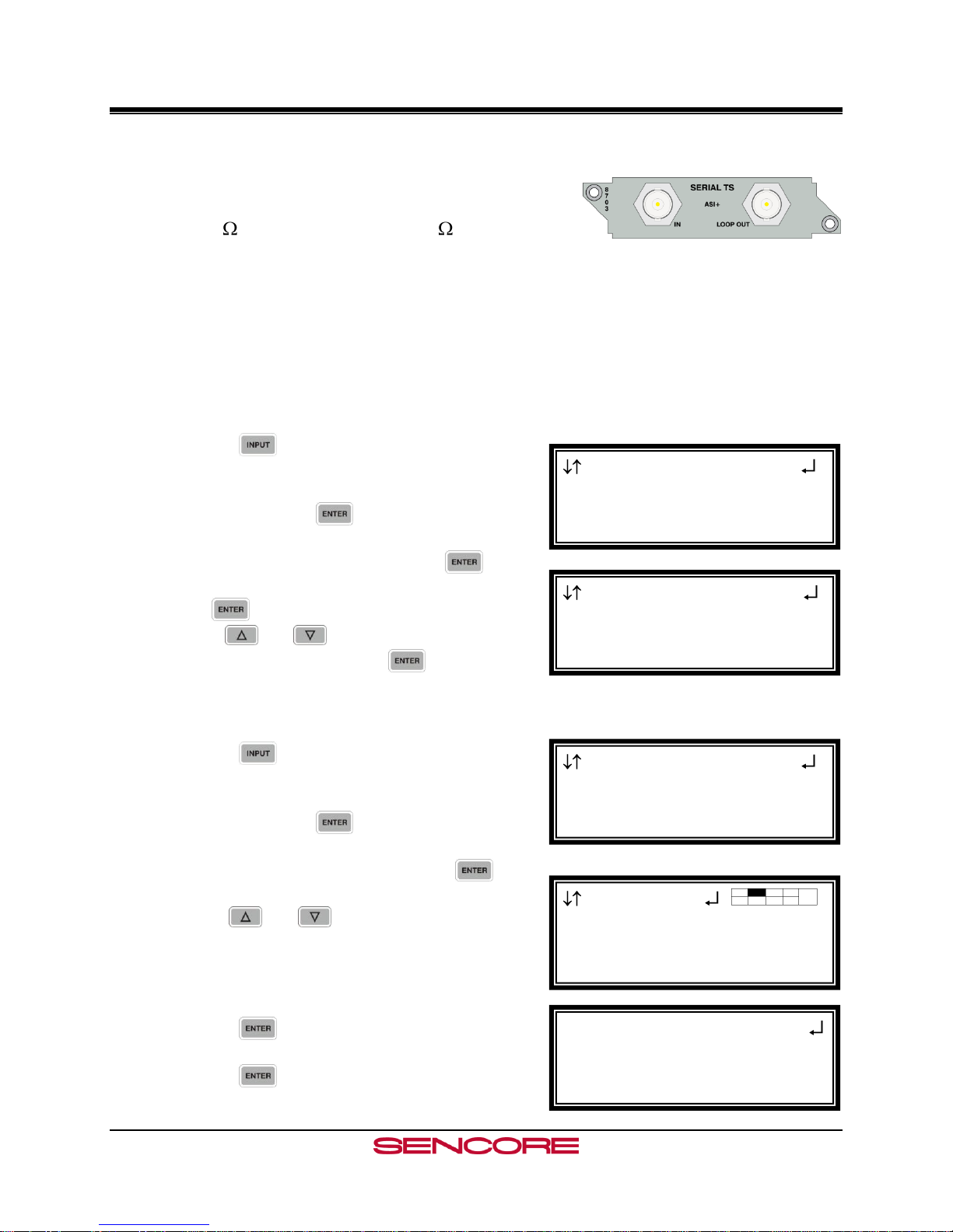
4.3 High Bit Rate ASI Input – Option 8703
General Information
Install Location: Any slot except 1-1 and 2-1.
I/O: (1) 75 Female BNC Input, (1) 75 Female BNC
Loop Out
Supported Formats: ASI
Description: This card provides DVB-ASI input for MPTS up to 160Mb/sec. The maximum
TS bitrate for the card is 160Mb/sec. The output on the card is a passive loop-through
and should be terminated with a 75Ohm terminator when not in use. The card cannot be
used to provide a TS output from another TS input on the unit.
Input Control
To enable this card as an input use the following steps.
1. Press the button.
Note: For Configuration 2 units, select RDS1 or
RDS2, then press .
2. Select “Active Input”, then press the
button.
3. Press twice to change the active input and
use the and buttons to select the input
to make active, and press the button to save
the changes.
Configure Input
1. Press the button.
Note: For Configuration 2 units, select RDS1 or
RDS2, then press .
2. Select “Input Modules”, and press the
button.
3. Use the and buttons to move the cursor
to the “ASI+” card of the specific slot (e.g. 2-2).
Notice the location diagram in the upper right
corner of the screen changes as the cursor moves
by each card.
4. Press the button once to display Status
screen for the ASI+ card.
5. Press the button again to display the Edit
screen for the ASI+ card.
Page 29
Page 31

MRD 3187B User Manual
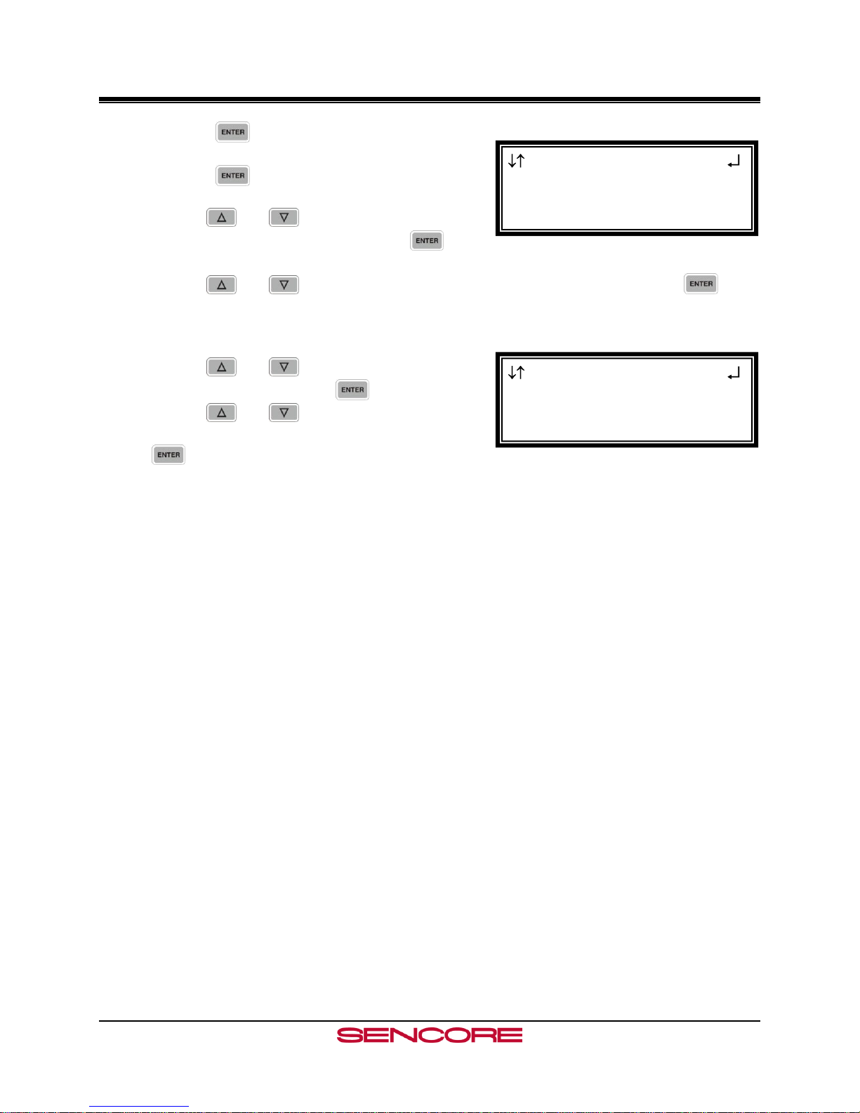
6. Press the button one more time.
7. Use the and buttons to change the
selection to, “yes,” then press the button.
Page 30
Page 32

MRD 3187B User Manual
Output
Audio 1-2
►SD Video 1-1
SD Video 1-1
►Video
SDI VANC Assignment
CMPST VBI Assignment
SD Video 1-1
►NTSC Ped:Disabled
SDI Clk:Pass on Fail
Format: 720x480i
4.4 Video Output (2 SD-SDI, 1 Composite) – Option 8704A/8704B
General Information
Install Location: 1-1 or (2-1, only on Configuration 2
units or Configuration 1 with dual decoders)
I/O: (2) 75 Female BNC SD-SDI outputs, (1) 75
Female BNC NTSC/PAL Composite output
Supported Formats: SD-SDI, NTSC/PAL Composite
Description: This card provides three mirrored outputs from any of the available input
option cards. Two of the outputs are SD-SDI and one is NTSC Composite. The 8704A
card provides Composite Color Phase Reference when used with Genlock and the 8731,
Genlock decoder.
Output Control
1. Press the button.
Note: For Configuration 2 units, select RDS1 or
RDS2, then press .
2. Use the and buttons to move the cursor
to the “SD Video” card of the specific slot (e.g.
1-1). Notice the location diagram in the upper
right corner of the screen changes as the cursor
moves by each card.
Video Settings
1. Use the and buttons to move the cursor
to, “Video,” then press the button to
display the Video Status screen for the video
output card.
2. Press the button again to display the Edit
screen for the video output card.
NTSC Pedestal
When the NTSC Ped is enabled it applies a 7.5IRE
pedestal to the black level of the Composite video
output.
1. Use the and buttons to move the
cursor to, “NTSC Ped:” then press the
button.
2. Use the and buttons to enable or
disable the pedestal, then press the
button to save the selection.
Page 31
Page 33

MRD 3187B User Manual
SD Video 1-1
NTSC Ped:Disabled
►SDI Clk:Pass on Fail
Format: 720x480i
SD Video 1-1
SDI Clk:Pass on Fail
►Format: 720x480i
4x3 29.97
SD Video 1-1
Format: 720x480i
4x3 29.97
►Disp Mode: Letterbox
SD Video 1-1
4x3 29.97
Disp Mode: Letterbox
►Auto AFD: Disabled
SDI Clock
This option sets how the SDI clock behaves upon
input failure. Pass on Fail will continue to send
the SDI clock and show the selected raster color
on the SDI outputs. Squelch will stop the SDI
clock and any equipment down the line will lose
SDI input.
1. Use the and buttons to move the
cursor to, “SDI Clk:” then press the
button.
2. Use the and buttons to set the
desired SDI clock mode (Pass on Fail,
Squelch), then press the button to
save the selection.
Video Format
1. Use the and buttons to move the
cursor to, “Format:” then press the
button.
2. Use the and buttons to select the
appropriate format, then press the
button to save the selection.
720x480i 4x3 29.97
720x480i 16x9 29.97
720x576i 16x9 25.00
720x576i 4x3 25.00
Display Mode
1. Use the and buttons to move the
cursor to, “Disp Mode:” then press the
button.
2. Use the and buttons to select the
appropriate display mode (Letterbox,
Cropped, Anamorph), then press the
button to save the selection.
Auto AFD
1. Use the and buttons to move the
cursor to, “Auto AFD:” then press the
button.
2. Use the and buttons to select the
appropriate mode (Enabled or Disabled),
then press the button to save the
selection.
Page 32
Page 34

MRD 3187B User Manual
SD Video 1-1
Disp Mode: Letterbox
Auto AFD: Disabled
►Raster Color: Black
SD Video 1-1
Video
►SDI VANC Assignment
CMPST VBI Assignment
SDI VANC 1-1
ADP
► EIA-608CC:Disabled
Line: 9
HD Video 2-1
►CMPST VBI Assignment
Overlay
Genlock Offset
Cmpst VBI
NTSC
► Line21 CC: Enabled
PAL
SDI VANC 1-1
ADP
EIA-608CC:Disabled
► Line: 9
Raster Color
This setting determines the color of the raster that
is output by the decoder when input is lost.
1. Use the and buttons to move the
cursor to, “Raster Color:” then press the
button.
2. Use the and buttons to select the
desired raster color (Black, White,
Yellow, Cyan, Green, Magenta, Red,
Blue), then press the button to save the
selection.
VANC Embedding
1. Use the and buttons to move the cursor
to, “SDI VANC Assignment,” then press the
button to view the Status screen.
2. Press the button once more to display the
edit menu.
3. Use the and buttons to move the cursor
to the desired ancillary data type, then press the
button.
4. Use the and buttons to choose
(Enabled or Disabled), then press the
button to save the selection.
5. Use the and buttons to select “Line:”
and press the button.
6. Use the and buttons to change the line
number in which the ancillary data will be
located.
Note: Use the above steps 3-6 to embed other
components on other lines.
Composite VBI Assignment
To setup Line 21 Closed Captions, Teletext, etc…
on the Composite output of this card use the
following steps:
1. Use the and buttons to move the
cursor to, “Cmpst VBI Assignment,” then
press the button.
2. To Enable or Disable any of the options (Line
21 CC, TTX, VPS, or WSS) press the button
on the selected option.
Page 33
Page 35

MRD 3187B User Manual
Overlay 1
►Type:Closed Caption
Overlay:NTSC
NTSC Srvc:1
SD Video 1-1
CMPST VBI Assignment
►Overlay
Genlock Offset
Overlay 1
Type:Closed Caption
►Overlay:NTSC
NTSC Srvc:1
3. Then use the and buttons to toggle
between Enabled and Disabled.
4. Press the button to save changes.
Overlay Settings
Overlays provide an easy to use OSD to help
troubleshoot problems, monitor stream characteristics,
or decode closed captioning.
CAUTION: All overlays will appear on the
downstream video.
1. Use the and buttons to move the cursor
to, “Overlay,” then press the button.
Type of Overlay
1. Use the and buttons to move the
cursor to, “Type:” then press the
button.
2. Use the and buttons to select which
overlay to display (Table, Closed
Caption, Service, Off), then press the
button to save the selection.
Overlay (Closed Caption)
Note: This menu changes depending upon which
overlay is set in “Type of Overlay” above.
1. Use the and buttons to move the
cursor to, “Overlay:” then press the
button.
2. Use the and buttons to select the
appropriate type of overlay (NTSC, DTVCC),
then press the button to save the
selection.
NTSC Service
Note: This menu is only available when the
“Overlay” setting is set to NTSC.
Page 34
Page 36

MRD 3187B User Manual
Overlay 1
Type:Table
Overlay:PSI PMT
►Screen Interaction
Overlay 1
Type:Table
►Overlay:PSI PMT
Screen Interaction
Overlay 1
Type:Closed Caption
Overlay:NTSC
►NTSC Srvc:1
Overlay 1
Type:Closed Caption
Overlay:DTVCC
►DTVCC Srvc:1
1. Use the and buttons to move the
cursor to, “NTSC Srvc:” then press the
button.
2. Use the and buttons to select
which NTSC CC Srvc to display on the
overlay (1-4), then press the button to
save the selection.
DTVCC Service
Note: This menu is only available when the
“Overlay” setting is set to DTVCC.
1. Use the and buttons to move the
cursor to, “DTVCC Srvc:” then press the
button.
2. Use the and buttons to select which
DTVCC Srvc to display on the overlay (1-7),
then press the button to save the
selection.
Overlay (Table)
Note: This menu changes depending on which
overlay is set in “Type of Overlay” above.
1. Use the and buttons to move the
cursor to, “Overlay:” then press the
button.
2. Use the and buttons to select the
appropriate type of overlay (PSI PAT, PSI
PMT, PSIP MGT, PSIP STT, PSIP
TVCT, PSIP EIT, PSIP EPG), then press
the button to save the selection.
Screen Interaction
This mode allows the user to page through the OSD
PSI/PSIP tables.
Note: This option will only be available if the type
of overlay is set to, “Table.”
1. Use the and buttons to move the
cursor to, “Screen Interaction,” then
press the button.
2. While this mode is enabled, the , ,
, and buttons will control the on-
Page 35
Page 37

MRD 3187B User Manual
Overlay 1
Screen Interaction
►Utc Offset: -06:00
Central
Overlay 1
Type: Service
►Overlay: Service Info
Output
SDI VANC Assignment
Overlay
►Small Format Disp
SFD 1-1
►Output Format:4x3
720x480i 29.97fps
Location: Top-Lt
screen PSI/PSIP tables. To exit the, “Screen
Interaction” mode press the button.
Coordinated Universal Time Offset
1. Use the and buttons to move the
cursor to, “Utc Offset:” then press the
button.
2. Use the and buttons to change to
the appropriate offset, then press the
button to save the selection.
See Appendix E for UTC values
Overlay (Service)
Note: This option only displays the Service Info.
Small Format Display
To setup the MRD 3187B to output a “Small Format
Display,” use the following steps:
1. Use the and buttons to move the cursor
to “Small Format Disp,” then press the
button.
2. Press the button again to change the
settings.
Format
1. While the cursor is on “Output Format:”
press the button to change the display
format.
2. Use the and buttons to change
from any of the following settings:
720x480i 4x3 29.97
720x480i 16x9 29.97
720x576i 16x9 25.00
720x576i 4x3 25.00
3. Press the button to save the settings.
Page 36
Page 38

MRD 3187B User Manual
SFD 1-1
Output Format:4x3
720x480i 29.97fps
►Location: Top-Lt
SFD Location
1. Use the and button to move the
cursor to “Location:” and then press the
button.
2. Use the and buttons to select one
of the following options:
Top-Lt Mid-Lt Btm-Lt
Top-Rt Mid-Rt Btm-Rt
Top-Ctr Mid-Ctr Btm-Ctr
3. Press the button to save the settings.
Page 37
Page 39

MRD 3187B User Manual
Output
►HD Video 2-1
Audio 2-2
HD Video 2-1
►Video
SDI VANC Assignment
Overlay
HD Video 2-1
►Select Format: manual
Format: 1920x1080i
16x9 29.97
4.5 Video Output (2 HD-SDI, 1 RGBHV/YPbPr) – Option 8705/8705A
General Information
Install Location: 1-1 or (2-1, only on Configuration 2
units or Configuration 1 with dual decoders)
I/O: (2) 75 HD-SDI Female BNC outputs, (1) 15-pin
D-sub Female analog output
Supported Formats: HD-SDI, YPbPr, RGBHV
Description: This card provides three mirrored outputs from any of the available input
option cards. Two of the outputs are HD-SDI and one is analog YPbPr/RGBHV.
Output Control
1. Press the button.
Note: For Configuration 2 units, select RDS1 or
RDS2, then press .
2. Use the and buttons to move the cursor
to the “HD Video” card of the specific slot (e.g.
2-1). Notice the location diagram in the upper
right corner of the screen changes as the cursor
moves by each card.
Video Settings
1. Use the and buttons to move the cursor
to, “Video,” then press the button to
display the Video Status screen for the video
output card.
2. Press the button again to display the Edit
screen for the video output card.
Select Format Setting
When in “Auto” mode, the unit will automatically pick the
format which is closest to the native format of the decoded
video in the elementary stream. When in “Manual” mode,
the format may be selected from the list of available output
formats listed under “Video Format” below.
1. Use the and buttons to move the
cursor to, “Select Format:” then press
the button.
2. Use the and buttons to select either
auto or manual mode, then press the
button to save the selection.
Page 38
Page 40

MRD 3187B User Manual
HD Video 2-1
Select Format: manual
►Format: 1920x1080i
16x9 29.97
HD Video 2-1
Format: 1920x1080i
16x9 29.97
►Anlg Out: RGBHV
HD Video 2-1
16x9 29.97
Anlg Out: RGB
►Disp Mode: Letterbox
Video Format
Note: This menu is only available if the “Select
Format” option is set to “manual.”
1. Use the and button to move the
cursor to, “Format:” then press the
button.
2. Use the and buttons to select the
desired output format, then press the
button to save the selection.
720x480i 16x9 29.97 1920x1080i 16x9 25.00
720x480i 4x3 29.97 1920x1080i 16x9 29.97
720x576i 16x9 25.00 1920x1080i 16x9 30.00
720x576i 4x3 25.00 1920×1080p 16×9 23.98*
1280x720p 16x9 50.00 1920×1080p 16×9 24.00*
1280x720p 16x9 59.94 1920×1080p 16×9 25.00*
1280x720p 16x9 60.00 1920×1080p 16×9 29.97*
1920×1080p 16×9 30.00*
* indicates that this setting is only available for the 8730A/8732
Note: “If either 480i or 576i video format is used the HD-SDI outputs are turned off and
only the analog output is enabled.
Analog Output Format
Note: If this setting is set incorrectly when using
an RGB monitor, the image will appear
green. If this setting is set incorrectly when
using a Component monitor, there will be no
video on the monitor.
1. Use the and buttons to move the
cursor to, “Anlg Out:” then press the
button.
2. Use the and buttons to select the
desired output format (RGBHV, YPbPr),
then press the button to save the
selection.
Display Mode
1. Use the and buttons to move the
cursor to, “Disp Mode:” then press the
button.
Page 39
Page 41

MRD 3187B User Manual
HD Video 2-1
Anlg Out:RGBHV
Display Mode:Letterbox
►Raster Color:Black
HD Video 1-1
Video
►SDI VANC Assignment
Overlay
SDI VANC 1-1
ADP
► EIA-608CC:Disabled
Line: 9
SDI VANC 1-1
ADP
EIA-608CC:Disabled
► Line: 9
2. Use the and buttons to select the
desired output size (Letterbox, Cropped),
then press the button to save the
selection.
Raster Color
This setting determines the color of the raster that
is output by the decoder when input is lost.
1. Use the and buttons to move the
cursor to, “Raster Color:” then press the
button.
2. Use the and buttons to select the
desired raster color (Black, White,
Yellow, Cyan, Green, Magenta,
Red, Blue), then press the button to
save the selection.
VANC Embedding
1. Use the and buttons to move the cursor
to, “SDI VANC Assignment,” then press the
button to view the Status screen.
2. Press the button once more to display the
edit menu.
3. Use the and buttons to move the cursor
to the desired ancillary data type, then press the
button.
4. Use the and buttons to choose
(Enabled or Disabled), then press the
button to save the selection.
5. Use the and buttons to select “Line:”
and press the button.
6. Use the and buttons to change the line
number in which the ancillary data will be
located.
Note: Use the above steps 3-6 to embed other
components on other lines.
Overlay Settings
Overlays provide an easy to use OSD to help
troubleshoot problems, monitor stream
characteristics, or decode closed captioning.
Page 40
Page 42

MRD 3187B User Manual
HD Video 2-1
SDI VANC Assignment
►Overlay
Genlock Offset
Overlay 2
Type: Closed Caption
►Overlay: NTSC
NTSC Srvc: 1
Overlay 2
►Type: Closed Caption
Overlay: NTSC
NTSC Srvc: 1
Overlay 2
Type: Closed Caption
Overlay: NTSC
►NTSC Srvc: 1
Overlay 2
Type: Closed Caption
Overlay: DTVCC
►DTVCC Srvc: 1
CAUTION: All overlays will appear on the
downstream video.
1. Use the and buttons to move the cursor
to, “Overlay,” then press the button.
Type of Overlay
1. Use the and buttons to move the
cursor to, “Type:” then press the button.
2. Use the and buttons to select which
overlay to display (Closed Caption,
Service, Table) then press the
button to save the selection.
Overlay (Closed Caption)
Note: This menu changes depending on which
overlay is set in “Type of Overlay” above.
1. Use the and buttons to move the
cursor to, “Overlay:” then press the
button.
2. Use the and buttons to select the
appropriate type of overlay (NTSC, DTVCC,
OFF), then press the button to save the
selection.
Closed Caption Number
NTSC
Note: This option will only be available if the TYPE
of overlay is set to, “Closed Caption” and
the OVERLAY is set to “NTSC.”
1. Use the and buttons to move the
cursor to, “NTSC Srvc:” then press the
button.
2. Use the and buttons to select the
desired number of closed caption to view (1-
4), then press the button to save the
selection.
DTVCC
Note: This option will only be available if the
TYPE of overlay is set to, “Closed
Caption” and the OVERLAY is set to
“DTVCC.”
Page 41
Page 43

MRD 3187B User Manual
Overlay 2
Type: Table
►Overlay: PSI PAT
Screen Interaction
Overlay 2
Type: Table
Overlay: PSI PMT
►Screen Interaction
Overlay 2
Screen Interaction
►Utc Offset: -06:00
Central
1. Use the and buttons to move the
cursor to, “DTVCC Srvc:” then press the
button.
2. Use the and buttons to select the
desired number of closed caption to view (1-
7), then press the button to save the
selection.
Overlay (Table)
Note: This menu changes depending on which
overlay is set in “Overlay”.
1. Use the and buttons to move the
cursor to, “Overlay:” then press the
button.
2. Use the and buttons to select the
appropriate type of overlay (PSI PAT, PSI
PMT, PSIP MGT, PSIP STT, PSIP
TVCT, PSIP EIT, PSIP EPG), then press
the button to save the selection.
Screen Interaction
This mode allows the user to page through the
on-screen PSI/PSIP tables.
Note: This option will only be available if the
type of overlay is set to, “Table.”
1. Use the and buttons to move the
cursor to, “Screen Interaction,” then
press the button.
2. While this mode is enabled, the ,
, , and buttons will control
the on-screen PSI/PSIP tables. To exit
the, “Screen Interaction” mode
press the button.
Coordinated Universal Time Offset
1. Use the and buttons to move
the cursor to, “Utc Offset:” then
press the button.
2. Use the and buttons to change
Page 42
Page 44

MRD 3187B User Manual
Overlay 1
Type: Service
►Overlay: Service Info
Output
SDI VANC Assignment
Overlay
►Small Format Disp
SFD 1-1
►Format:1920x1080i
16x9 29.97
SFD Location:Top-Lt
SFD 1-1
Format:1920x1080i
16x9 29.97
►SFD Location:Top-Lt
to the appropriate offset, then press the
button to save the selection.
Overlay (Service)
Note: This option only displays the Service Info.
Small Format Display
To setup the MRD 3187B to output a “Small Format
Display,” use the following steps:
1. Use the and buttons to move the cursor
to “Small Format Disp,” then press the
button.
2. Press the button again to change the
settings.
Format
1. While the cursor is on “Format:” press the
button to change the display format.
2. Use the and buttons to change
from any of the following settings:
720x480i 16x9 29.97 1920x1080i 16x9 25.00
720x480i 4x3 29.97 1920x1080i 16x9 29.97
720x576i 16x9 25.00 1920x1080i 16x9 30.00
720x576i 4x3 25.00 1920x1080p 16x9 23.98
1280x720p 16x9 50.00 1920x1080p 16x9 24.00
1280x720p 16x9 59.94 1920x1080p 16x9 25.00
1280x720p 16x9 60.00 1920x1080p 16x9 29.97
1920x1080p 16x9 30.00
3. Press the button to save the settings.
SFD Location
1. Use the and button to move the
cursor to “SFD Location:” and then press
the button.
2. Use the and buttons to select one
of the following options:
Top-Lt Mid-Lt Btm-Lt
Top-Rt Mid-Rt Btm-Rt
Top-Ctr Mid-Ctr Btm-Ctr
3. Press the button to save the settings.
Page 43
Page 45

MRD 3187B User Manual
Anlg Video 1-1
►Select Format: manual
Format: 1920x1080i
16x9 29.97
Anlg Video 1-1
►Video
Cmpst VBI Assignment
Overlay
Output
►Anlg Video 1-1
Audio 1-2
4.6 Video Output (1 RGBHV/YPbPr, 1 Composite) - Option 8706A
General Information
Install Location: 1-1 or (2-1 only on Configuration 2
units or Configuration 1 units with dual decoders)
I/O: (1) 75 Female BNC NTSC/PAL Composite
output, (1) 15-pin D-sub Female analog output
Supported Formats: NTSC/PAL Composite, YPbPr, RGBHV
Description: Analog only, video output card that can output either high definition or
standard definition formats. There are two outputs on the card. One BNC for composite and
one 15-pin D-sub for composite
Output Control
1. Press the button.
Note: For Configuration 2 units, select RDS1 or RDS2, then press .
2. Use the and buttons to move the cursor
to the “Anlg Video” card of the specific slot
(e.g. 1-1), then press the button. Notice the
location diagram in the upper right corner of the
screen changes as the cursor moves by each
card.
Video Settings
1. Use the and buttons to move the cursor
to, “Video,” then press the button to
display the Video status screen for the video
output card.
2. Press the button again to display the Edit
screen for the video output card.
Select Format Setting
When in “Auto” mode, the unit will automatically pick the format which is closest to the
native format of the decoded video in the elementary stream. When in “Manual” mode,
the format may be selected from the list of available output formats listed under “Video
Format” below.
1. Use the and buttons to move the
cursor to, “Select Format:” then press
the button.
2. Use the and buttons to select either
auto or manual mode, then press the
button to save the selection.
Page 44
Page 46

MRD 3187B User Manual
Anlg Video 1-1
Select Format: manual
►Format: 1920x1080i
16x9 29.97
Anlg Video 1-1
Format: 1920x1080i
16x9 29.97
►Anlg Out: RGBHV
Anlg Video 1-1
NTSC offset: Enabled
►Disp Mode: Letterbox
Raster Color: Black
Anlg Video 1-1
►NTSC offset: Enabled
Disp Mode: Letterbox
Raster Color: Black
Video Format
Note: This menu is only available if the “Select
Format” option is set to “manual.”
1. Use the and buttons to move the
cursor to, “Format:” then press the
button.
2. Use the and buttons to select the
appropriate output format, then press the
button to save the selection.
720x480i 16x9 29.97 1280x720p 16x9 59.94
720x480i 4x3 29.97 1280x720p 16x9 60.00
720x576i 16x9 25.00 1920x1080i 16x9 25.00
720x576i 4x3 25.00 1920x1080i 16x9 29.97
1280x720p 16x9 50.00 1920x1080i 16x9 30.00
Analog Output Format
Note: If this setting is set incorrectly when using an RGB monitor, the image will appear
green. If this setting is set incorrectly when using a Component monitor, there will
be no video on the monitor.
1. Use the and buttons to move the
cursor to, “Anlg Out:” then press the
button.
2. Use the and buttons to select the
desired output format (RGBHV, YPbPr),
then press the button to save the
selection.
NTSC Ped
When the NTSC Ped is enabled it applies a 7.5IRE
offset to the black level of the Composite video
output.
1. Use the and buttons to move the
cursor to, “Format:” then press the
button.
2. Use the and buttons to enable or
disable the NTSC offset, then press the
button to save the selection.
Display Mode
1. Use the and buttons to move the
cursor to, “Disp Mode:” then press the
button.
Page 45
Page 47

MRD 3187B User Manual
Anlg Video 1-1
NTSC offset: Enabled
Disp Mode: Letterbox
►Raster Color: Black
HD Video 2-1
►CMPST VBI Assignment
Overlay
Genlock Offset
Cmpst VBI 2-1
NTSC
► Line21 CC:Disabled
PAL
Anlg Video 1-1
Disp Mode: Letterbox
►Auto AFD:Disabled
Raster Color: Black
2. Use the and buttons to select either
(Letterbox, Cropped), then press the
button to save the selection.
Auto AFD
AFD or Active Format Description, is a standard
set of codes that if sent in the MPEG transport
stream is interpreted by the MRD 3187A into a
certain aspect ratio and active picture
characteristics.
1. Use the and buttons to move the
cursor to, “Auto AFD:” then press the
button.
2. Use the and buttons to select the
appropriate mode (Enabled or Disabled),
then press the button to save the
selection.
Raster Color
1. Use the and buttons to move the
cursor to, “Raster Color:” then press the
button.
2. Use the and buttons to select the
desired raster color (Black, White,
Yellow, Cyan, Green, Magenta,
Red, Blue), then press the button to
save the selection.
Composite VBI Assignment
To setup Line 21 Closed Captions, Teletext, etc…
on the Composite output of this card use the
following steps:
1. Use the and buttons to move the
cursor to, “Cmpst VBI Assignment,” then
press the button.
2. To Enable or Disable any of the options (Line
21 CC, TTX, VPS, or WSS) press the
button on the selected option.
3. Then use the and buttons to toggle
between Enabled and Disabled.
4. Press the button to save changes.
Page 46
Page 48

MRD 3187B User Manual
HD Video 2-1
CMPST VBI Assignment
►Overlay
Genlock Offset
Overlay 2
Type: Closed Caption
►Overlay: NTSC
NTSC Srvc: 1
Overlay 2
►Type: Closed Caption
Overlay: NTSC
NTSC Srvc: 1
Overlay 2
Type: Closed Caption
Overlay: NTSC
►NTSC Srvc: 1
Overlay Settings
CAUTION: If Info (PSI/PSIP) data is turned on, the
overlay will appear on downstream video.
The same is true if Closed Caption overlay
is turned on.
1. Use the and buttons to move the cursor
to, “Overlay,” then press the button.
Type of Overlay
1. Use the and buttons to move the
cursor to, “Type:” then press the
button.
2. Use the and buttons to select which
overlay to display (Table, Closed
Caption, Service, OFF), then press the
button to save the selection.
Overlay (Closed Caption)
Note: This menu changes depending on which
overlay is set in “Type of Overlay” above.
1. Use the and buttons to move the
cursor to, “Overlay:” then press the
button.
2. Use the and buttons to select the
appropriate type of overlay (NTSC, DTVCC),
then press the button to save the
selection.
Closed Caption Number
NTSC
Note: This option will only be available if the
TYPE of overlay is set to, “Closed
Caption” and the OVERLAY is set to
“NTSC.”
1. Use the and buttons to move
the cursor to, “NTSC Srvc:” then press
the button.
2. Use the and buttons to select
the desired number of closed caption to
Page 47
Page 49

MRD 3187B User Manual
Overlay 2
Type: Table
►Overlay: PSI PAT
Screen Interaction
Overlay 2
Type: Table
Overlay: PSI PMT
►Screen Interaction
Overlay 2
Type: Closed Caption
Overlay: DTVCC
►DTVCC Srvc: 1
view (1-4), then press the button to
save the selection.
DTVCC
Note: This option will only be available if the
TYPE of overlay is set to, “Closed
Caption” and the OVERLAY is set to
“DTVCC.”
1. Use the and buttons to move
the cursor to, “DTVCC Srvc:” then
press the button.
2. Use the and buttons to select the
desired number of closed caption to view
(1-7), then press the button to save
the selection.
Overlay (Table)
Note: This menu changes depending on which
overlay is set in “Overlay”.
1. Use the and buttons to move the
cursor to, “Overlay:” then press the
button.
2. Use the and buttons to select the
appropriate type of overlay (PSI PAT, PSI
PMT, PSIP MGT, PSIP STT, PSIP
TVCT, PSIP EIT, PSIP EPG), then press
the button to save the selection.
Screen Interaction
This mode allows the user to page through the
on-screen PSI/PSIP tables.
Note: This option will only be available if the
type of overlay is set to, “Table”
1. Use the and buttons to move
the cursor to, “Screen Interaction,”
then press the button.
2. While this mode is enabled, the ,
, , and buttons will control
the on-screen PSI/PSIP tables. To exit the,
“Screen Interaction” mode press the
button.
Page 48
Page 50

MRD 3187B User Manual
Overlay 1
Type: Service
►Overlay: Service Info
Overlay 1
Screen Interaction
►Utc Offset: -06:00
Central
Output
SDI VANC Assignment
Overlay
►Small Format Disp
SFD 1-1
►Format:1920x1080i
16x9 29.97
SFD Location:Top-Lt
Coordinated Universal Time Offset
1. Use the and buttons to move
the cursor to, “Utc Offset:” then
press the button.
2. Use the and buttons to change
to the appropriate offset, then press the
button to save the selection.
Overlay (Service)
Note: This option only displays the Service Info.
Small Format Display
To setup the MRD 3187B to output a “Small Format
Display,” use the following steps:
1. Use the and buttons to move the cursor
to “Small Format Disp,” then press the
button.
2. Press the button again to change the
settings.
Format
1. While the cursor is on “Format:” press the
button to change the display format.
2. Use the and buttons to change
from any of the following settings:
720x480i 16x9 29.97 1920x1080i 16x9 25.00
720x480i 4x3 29.97 1920x1080i 16x9 29.97
720x576i 16x9 25.00 1920x1080i 16x9 30.00
720x576i 4x3 25.00 1920×1080p 16×9 23.98*
1280x720p 16x9 50.00 1920×1080p 16×9 24.00*
1280x720p 16x9 59.94 1920×1080p 16×9 25.00*
1280x720p 16x9 60.00 1920×1080p 16×9 29.97*
1920×1080p 16×9 30.00*
* indicates that this setting is only available for the 8730A/8732
Page 49
Page 51

MRD 3187B User Manual
SFD 1-1
Format:1920x1080i
16x9 29.97
►SFD Location:Top-Lt
Note: “If either 480i or 576i video format is used the HD-SDI outputs are turned off and
only the analog output is enabled.
3. Press the button to save the settings.
SFD Location
1. Use the and button to move the
cursor to “SFD Location:” and then press
the button.
2. Use the and buttons to select one
of the following options:
Top-Lt Mid-Lt Btm-Lt
Top-Rt Mid-Rt Btm-Rt
Top-Ctr Mid-Ctr Btm-Ctr
3. Press the button to save the settings.
Page 50
Page 52

MRD 3187B User Manual
Output
Anlg Video 1-1
►Audio 2-2
Audio 2-2
Digital Audio:
► Out1: Audio 1 – PCM
Out2: Audio 2 – PCM
4.7 Audio Output (DolbyE, AES Digital, Analog) – Option 8707A
General Information
Install Location: Any slot except 1-1 and 2-1.
I/O: (2) 75 Female BNC digital outputs, (1) 15-pin D-
sub Male analog output
Supported Formats: Raw, PCM, Dolby E
Description: This card provides parsed DolbyE compressed audio, two digital audio outputs,
and two analog audio pair outputs. It provides the audio from two audio decoder
processors. Two 8707A cards can be installed to provide Raw and PCM digital audio
outputs from four audio decoder processors (Only in Configuration 2 units for separate
inputs or Configuration 1 Dual Decoder units for the same input).
Output Control
1. Press the button.
Note: For Configuration 2 units, select RDS1 or
RDS2, then press .
2. Use the and buttons to move the cursor
to the “Audio” card of the specific slot (e.g. 2-
2), then press the button. Notice the
location diagram in the upper right corner of the
screen changes as the cursor moves by each
card.
3. Press the button one more time to move from
the Status screen to the Edit screen.
Digital Audio Settings
1. Use the and buttons to move the
cursor to, “Digital Audio: Out1:” then
press the button.
2. Use the and buttons to select the
audio decoder and output format desired
(Audio X, Raw, PCM), then press the
button to save the selection.
Note: The above steps apply to “Digital Audio:
Out2:” as well.
Note: The “X” of “Audio X,” in the step above, will be (1, 2, Off) for a Configuration 1
Single Decoder unit or any Configuration 2 unit, and it will be (1, 2, 3, 4, Off) for a
Configuration 1 Dual Decoder unit.
Page 51
Page 53

MRD 3187B User Manual
Audio 2-2
Analog Audio:
► Ch1: Audio 1
Ch2: Audio 2
Audio 2-2
Ch1: Audio 1
Ch2: Audio 2
► Level: 1
Analog Audio Settings
1. Use the and buttons to move the
cursor to, “Analog Audio: Ch1:” then
press the button.
2. Use the and buttons to select the
desired audio to output (Audio X), then
press the button to save the selection.
Note: The “X” of “Audio X,” in the step above,
will be (1, 2, Off) for a Configuration 1
Single Decoder unit or any Configuration
2 unit, and it will be (1, 2, 3, 4, Off) for a
Configuration 1 Dual Decoder unit.
Note: The above steps apply to “Analog Audio:
Ch2:” as well.
Output Level
1. Use the and buttons to move the
cursor to, “Level:” then press the
button.
2. Use the and buttons to select the
desired level (1-9), then press to save
the selection.
Note: The level 7 is approx. 0 Db and each
number increment is approx. 2.5 Db.
Page 52
Page 54

MRD 3187B User Manual
Output
►HD/SD SDI Anlg Video
Audio 2-2
SDI Anlg Video 2-1
►Video
HD Settings
SD Settings
SDI Anlg Video 2-1
►Select Format: manual
Format: 1920x1080i
16x9 29.97
4.8 Dual Video Output (2 SDI, 1 RGBHV/YPbPr/Composite) – Option 8708
General Information
Install Location: 1-1 or (2-1 only on Configuration 2
units or Configuration 1 units with dual decoders)
I/O: (2) 75 HD-SDI Female BNC outputs, (1) 15-pin
D-sub Female analog output
Supported Formats: HD-SDI, SD-SDI, YPbPr, RGBHV, and Composite
Description: This card provides three mirrored outputs from any of the available input
option cards. Two of the outputs are any combination of HD-SDI or SD-SDI and one is
analog YPbPr/RGBHV/Composite.
Output Control
1. Press the button.
2. Use the and buttons to move the cursor
to the “HD/SD SDI Anlg Video” card of the
specific slot (e.g. 2-1). Notice the location
diagram in the upper right corner of the screen
changes as the cursor moves by each card.
Video Settings
1. Use the and buttons to move the cursor
to, “Video,” then press the button to
display the Video Status screen for the video
output card.
2. Press the button again to display the Edit
screen for the video output card.
Select Format Setting
When in “Auto” mode, the unit will automatically pick the
format which is closest to the native format of the decoded
video in the elementary stream. When in “Manual” mode,
the format may be selected from the list of available output
formats listed under “Video Format” below.
1. Use the and buttons to move the
cursor to, “Select Format:” then press
the button.
2. Use the and buttons to select either
auto or manual mode, then press the
button to save the selection.
Video Format
Note: This menu is only available if the “Select
Format” option is set to “manual.”
Page 53
Page 55

MRD 3187B User Manual
SDI Anlg Video 2-1
Select Format: manual
►Format: 1920x1080i
16x9 29.97
SDI Anlg Video 2-1
Analog
► Anlg Out:RGBHV
NTSC Ped:Disabled
SDI Anlg Video 2-1
SDI
► Output A:SD
Output B:HD
1. Use the and button to move the
cursor to, “Format:” then press the
button.
2. Use the and buttons to select the
desired output format, then press the
button to save the selection.
720x 480i 16x9 29.97 1920x1080i 16x9 30.00
720x 480i 4x3 29.97 1920x1080psF 16x9 23.98
720x 576i 4x3 25.00 1920x1080psF 16x9 24.00
720x 576i 16x9 25.00 1920x1080p 16x9 23.98
1280x720p 16x9 60.00 1920x1080p 16x9 24.00
1280x720p 16x9 59.94 1920x1080p 16x9 25.00
1280x720p 16x9 50.00 1920x1080p 16x9 29.97
1920x1080i 16x9 25.00 1920x1080p 16x9 30.00
1920x1080i 16x9 29.97
SDI Output Setup
Follow the steps in this section to set the outputs to
SD-SDI and HD-SDI.
1. Use the and button to move the
cursor to, “Output A:” then press the
button.
2. Use the and buttons to select the
desired output format (SD or HD), then
press the button to save the selection.
Note: Repeat the steps above to change to the
desired output setting for “Output B:”
Analog Output Format
Note: If this setting is set incorrectly when using
an RGB monitor, the image will appear
green. If this setting is set incorrectly when
using a Component monitor, there will be no
video on the monitor.
1. Use the and buttons to move the
cursor to, “Anlg Out:” then press the
button.
2. Use the and buttons to select the
desired output format (RGBHV, YPbPr,
Composite), then press the button to
save the selection.
Page 54
Page 56

MRD 3187B User Manual
SDI Video 2-1
►Disp Mode: Pillarbars
Video Loss Mode:
Display Raster
SDI Anlg Video 2-1
Analog
Anlg Out:RGBHV
► NTSC Ped:Black 0
SDI Anlg Video 2-1
Anlg Out:RGBHV
NTSC Ped:Disabled
►Raster Color:Black
SDI Video 2-1
Video
►HD Settings
SD Settings
SDI Video 2-1
Disp Mode: Pillarbars
►Video Loss Mode:
Display Raster
3. Use the and buttons to move the
cursor to, “NTSC Ped:” then press the
button.
4. Use the and buttons to change the
“NTSC Ped:” to either “Black 0” or “Black
7.5”, then press the button to save the
selection.
Raster Color
This setting determines the color of the raster that
is output by the decoder when input is lost.
1. Use the and buttons to move the
cursor to, “Raster Color:” then press the
button.
2. Use the and buttons to select the
desired raster color (Black, White,
Yellow, Cyan, Green, Magenta,
Red, Blue), then press the button to
save the selection.
HD Settings
1. Use the and buttons to move the cursor
to, “HD Settings,” then press the button
to display the Status screen for the HD video
output settings.
2. Press the button again to display the Edit
screen for the HD video output settings.
Display Mode
1. Use the and buttons to move the
cursor to, “Disp Mode:” then press the
button.
2. Use the and buttons to select the
desired output size (Pillarbars,
Cropped), then press the button to save
the selection.
Video Loss Mode
1. Use the and buttons to move the
cursor to, “Video Loss Mode:” then press
the button.
2. Use the and buttons to choose
between (Display Raster, Disable
Page 55
Page 57

MRD 3187B User Manual
SDI Video 2-1
Video Loss Mode:
Display Raster
►Auto AFD:Disabled
SD SDI Video 2-1
Video
HD Settings
►SD Settings
SDI VANC 2-1
ADP
► EIA-608CC:Disabled
Line:9
SDI Video 2-1
Display Raster
Auto AFD:Disabled
►SDI VANC Assign
Output), then press the button to save
the selection.
Auto AFD
1. Use the and buttons to move the
cursor to, “Auto AFD:” then press the
button.
2. Use the and buttons to enable or
disable AFD, then press the button to
save the selection.
SDI VANC Assignment
To edit the SDI VANC Assignment, use the
following steps.
1. Use the and buttons to move the
cursor to, “SDI VANC Assign” then press
the button to display the status screen
for the VANC.
2. Press the button once more to enter the
Edit screen.
ADP
To enable items in the VANC and assign a
line for each item, use the following steps.
1. Use the and buttons to move the
cursor to the desired type of closed
captioning (EIA-608CC, EIA-708CC,
TTX S2031M, Source ID, or 127
S2031M), then press the button.
2. Use the and buttons to choose
“Enabled or Disabled” then select
the “Line” on which to embed. Press the
button to save the selection.
Note: Repeat steps 1-4 above to change EIA-
708CC, TTX S2031M, Source ID, and 127
S2031M.
SD Settings
1. Use the and buttons to move the cursor
to, “SD Settings,” then press the button
to display the Status screen for the SD video
output settings.
2. Press the button again to display the Edit
Page 56
Page 58

MRD 3187B User Manual
SD SDI Video 2-1
►SD Mode: Cropped
Video Loss Mode:
Display Raster
SD SDI Video 2-1
Video Loss Mode:
Display Raster
►Auto AFD:Disabled
SD SDI Video 2-1
Disp Mode: Pillarbars
►Video Loss Mode:
Display Raster
SD SDI Video 2-1
Auto AFD:Disabled
►SDI VANC Assign
Cmpst VBI Assignment
SD SDI VANC 2-1
ADP
► EIA-608CC:Disabled
Line:9
screen for the SD video output settings.
Display Mode
1. Use the and buttons to move the
cursor to, “Disp Mode:” then press the
button.
2. Use the and buttons to select the
desired output size (Letterbox,
Anamorph, or Cropped), then press the
button to save the selection.
Video Loss Mode
1. Use the and buttons to move the
cursor to, “Video Loss Mode:” then press
the button.
2. Use the and buttons to choose
between (Display Raster, Disable
Output), then press the button to save
the selection.
Auto AFD
1. Use the and buttons to move the
cursor to, “Auto AFD:” then press the
button.
2. Use the and buttons to enable or
disable AFD, then press the button to
save the selection.
SDI VANC Assignment
To edit the SDI VANC Assignment, use the
following steps.
1. Use the and buttons to move the
cursor to, “SDI VANC Assign” then press
the button to display the status screen
for the VANC.
2. Press the button once more to enter the
Edit screen.
ADP
To enable items in the VANC and assign a
line for each item, use the following steps.
1. Use the and buttons to move
the cursor to the desired type of closed
Page 57
Page 59

MRD 3187B User Manual
SD SDI Video 2-1
NTSC Waveforms
► Line21CC:Enabled
AMOL:Disabled
SD SDI Video 2-1
PAL Waveforms
► TTX:Enabled
VPS:Disabled
SD SDI Video 2-1
Auto AFD:Disabled
SDI VANC Assign
►Cmpst VBI Assignment
SD SDI VANC 2-1
ADP
EIA-608CC:Disabled
► Line:9
captioning (EIA-608CC, EIA-708CC,
TTX S2031M, Source ID, or 127
S2031M), then press the button.
2. Use the and buttons to choose
“Enabled or Disabled” then select
the “Line” on which to embed. Press the
button to save the selection.
Note: Repeat steps 1-4 above to change EIA-
708CC, TTX S2031M, Source ID, and 127
S2031M.
NTSC Waveforms
To enable NTSC items, use the following
steps.
1. Use the and buttons to move
the cursor to, “Line21CC:” then press
the button.
2. Use the and buttons to enable
or disable “Line21CC”, then press the
button to save the selection.
Note: Repeat steps 1-2 above to change AMOL,
and TVG2x.
PAL Waveforms
To enable PAL items, use the following steps.
1. Use the and buttons to move
the cursor to, “TTX:” then press the
button.
2. Use the and buttons to enable
or disable “TTX”, then press the
button to save the selection.
Note: Repeat steps 1-2 above to change VPS,
and WSS.
Composite VBI Assignment
To edit the Composite VBI Assignment, use the
following steps.
1. Use the and buttons to move the
cursor to, “Cmpst VBI Assignment” then
press the button to display the status
screen for the VBI.
Page 58
Page 60

MRD 3187B User Manual
SD SDI Video 2-1
NTSC Waveforms
► Line21CC:Enabled
AMOL:Disabled
SD SDI Video 2-1
PAL Waveforms
► TTX:Enabled
VPS:Disabled
2. Press the button once more to enter the
Edit screen.
NTSC Waveforms
To enable NTSC items, use the following
steps.
1. Use the and buttons to move
the cursor to, “Line21CC:” then press
the button.
2. Use the and buttons to enable
or disable “Line21CC”, then press the
button to save the selection.
Note: Repeat steps 1-2 above to change AMOL,
and TVG2x.
PAL Waveforms
To enable PAL items, use the following steps.
1. Use the and buttons to move
the cursor to, “TTX:” then press the
button.
2. Use the and buttons to enable
or disable “TTX”, then press the
button to save the selection.
Note: Repeat steps 1-2 above to change VPS,
and WSS.
Page 59
Page 61

MRD 3187B User Manual
Input
MPEG/IP 1-3
►DVB-S/S2 2-2
Input
►Active Input
Backup Mode
Input Modules
Active Input
Active Input:
► DVB-S/S2 2-2
Input
Active Input
Backup Mode
►Input Modules
4.9 Dual Input DVB-S/DVB-S2 Receiver – Option 8710/8710A
General Information
Install Location: Any slot except 1-1 or 2-1.
I/O: (2) 75 Female F Connectors
Supported Formats: DVB-S/DVB-S2
Description: This card will input a satellite L-band (950MHz – 2150MHz) signal for
demodulation of KU-band or C-band DVB-S QPSK signals or DVB-S2 QPSK/8PSK
signals. The symbol rate ranges from 1MSym/s to 45MSym/s for DVB-S and 130MSym/s for DVB-S2. This card does not provide any power to the dish LNB. The
“Input” LED will only illuminate if the card detects frequency, symbol rate, FEC lock
(Carrier Lock), and TS sync (Sync Lock). The card provides A and B inputs, which may
be independently configured, but only one may be used at a time.
Note: This card does not provide power to the dish LNB
Input Control
To enable this card as an input use the following steps.
1. Press the button.
Note: For Configuration 2 units, select RDS1 or
RDS2, then press .
2. Select “Active Input”, then press the
button.
3. Press twice to change the active input and
use the and buttons to select the input
to make active, and press the button to save
the changes.
Configure Input
1. Press the button.
Note: For Configuration 2 units, select RDS1 or
RDS2, then press .
2. Select “Input Modules”, and press the
button.
3. Use the and buttons to move the cursor
to the “DVB-S/S2” card of the specific slot (e.g.
2-2). Notice the location diagram in the upper
right corner of the screen changes as the cursor
moves by each card.
Page 60
Page 62

MRD 3187B User Manual
DVB-S/S2 2-2
►Selected I/O: no
Source: A
Input A
DVB-S/S2 2-2
DVB Mode: DVB-S2
► Freq: 1250.0 MHz
Sym Rt: 27.0000 MSps
DVB-S/S2 2-2
Selected I/O: yes
►Source: A
Input A
DVB-S/S2 2-2
Input A
► DVB Mode: DVB-S2
Freq: 1250.0 MHz
4. Press the button once to display the Status
screen for the DVB-S/S2 card.
5. Press the button again to display the Edit
screen for the DVB-S/S2 card.
6. Use the and buttons to move the cursor
to, “Selected I/O:” then press the
button.
7. Use the and buttons to change the
selection to, “yes,” then press the button.
Source
This option will select which input, on the back of
the card, will be active.
1. Use the and buttons to move the cursor
to, “Source:” then press the button.
2. Use the and buttons to select which
input to be active (A, B), then press the
button to save the selection.
Input A
These settings correspond to the input on “Source A.”
DVB Mode
The DVB-S/S2 card can receive either DVB-S or
DVB-S2 transmission.
1. Use the and buttons to move the
cursor to, “DVB Mode:” then press the
button.
2. Use the and buttons to select either
(DVB-S, DVB-S2), then press the
button to save the selection.
Frequency A
The DVB-S/S2 card tunes by the L-band frequency rather than the transponder frequency
or local oscillator value. The L-band frequency is the difference between the downlink
transponder frequency and the LNB local oscillator frequency.
1. Use the and buttons to move the
cursor to, “Freq:” then press the button.
2. Use the and buttons to select the
column to edit and use the and
buttons to change the frequency (950MHz –
2150MHz), then press the button to
save the selection.
Page 61
Page 63

MRD 3187B User Manual
DVB-S/S2 2-2
DVB Mode: DVB-S2
Freq: 1250.0 MHz
► Sym Rt: 27.0000 MSps
DVB-S/S2 2-2
DVB Mode: DVB-S
► Freq: 1390.0 MHz
Sym Rt: 30.0000 MSps
DVB-S/S2 2-2
Input B
► DVB Mode: DVB-S
Freq: 1390.0 MHz
Symbol Rate A
1. Use the and buttons to move the
cursor to, “Sym Rt:” then press the
button.
2. Use the and buttons to select the
column to edit and use the and
buttons to change the symbol rate.
Note: 1 – 45MSymbols/s for DVB-S,
and 1 – 30MSymbols/s for DVB-S2.
3. Then press the button to save the
selection.
Input B
These settings correspond to the input on “Source B.”
DVB Mode
The DVB-S/S2 card can receive either DVB-S or
DVB-S2 transmission.
1. Use the and buttons to move the
cursor to, “DVB Mode:” then press the
button.
2. Use the and buttons to select either
(DVB-S, DVB-S2), then press the
button to save the selection.
Frequency B
The DVB-S/S2 card tunes by the L-band
frequency rather than the transponder frequency or
local oscillator value. The L-band frequency is the
difference between the downlink transponder
frequency and the LNB local oscillator frequency.
1. Use the and buttons to move the
cursor to, “Freq:” then press the
button.
2. Use the and buttons to select the
column to edit and use the and
buttons to change the frequency (950MHz –
2150MHz), then press the button to
save the selection.
Page 62
Page 64

MRD 3187B User Manual
DVB-S/S2 2-2
DVB Mode: DVB-S
Freq: 1390.0 MHz
► Sym Rt: 30.0000 MSps
Symbol Rate B
1. Use the and buttons to move the
cursor to, “Sym Rate:” then press the
button.
2. Use the and buttons to select the
column to edit and use the and
buttons to change the symbol rate.
Note: 1 – 45MSymbols/s for DVB-S,
and 1 – 30MSymbols/s for DVB-S2.
3. Then press the button to save the
selection.
Page 63
Page 65

MRD 3187B User Manual
Input
MPEG/IP 1-3
►AdvPSK 2-2
Input
►Active Input
Backup Mode
Input Modules
Active Input
Active Input:
► AdvPSK 2-2
Input
Active Input
Backup Mode
►Input Modules
4.10 Dual Input ASM Receiver – Option 8711
General Information
Install Location: Any slot except 1-1 or 2-1.
I/O: (2) 75 Female F Connectors
Supported Formats: DVB-S/DVB-S2
Description: This card will input a satellite L-band (950MHz – 2150MHz) signal for
demodulation of KU-band, C-band, or X-band DVB-QPSK, 8PSK, or Adv-QPSK
signals. All these modes are available using Turbo Coded forward error correction. The
DVB-QPSK mode also supports legacy DVB FEC. The symbol rate ranges from
0.256MSym/s to 30MSym/s for all modulation types. This card does not provide any
power to the dish LNB. The “Input” LED will only illuminate if the card detects
frequency, symbol rate, FEC lock (Carrier Lock), and TS sync (Sync Lock). The card
provides A and B inputs, which may be independently configured, but only one may be
active at a time.
Note: This card does not provide power to the dish LNB
Input Control
To enable this card as an input use the following steps.
1. Press the button.
Note: For Configuration 2 units, select RDS1 or
RDS2, then press .
2. Select “Active Input”, then press the
button.
3. Press twice to change the active input and
use the and buttons to select the input
to make active, and press the button to save
the changes.
Configure Input
1. Press the button.
Note: For Configuration 2 units, select RDS1 or
RDS2, then press .
2. Select “Input Modules”, and press the
button.
3. Use the and buttons to move the cursor
to the “AdvPSK” card of the specific slot (e.g. 2-
Page 64
Page 66

MRD 3187B User Manual
AdvPSK 2-2
►Selected I/O: no
Source: A
Input A
AdvPSK 2-2
Selected I/O: yes
►Source: A
Input A
AdvPSK 2-2
Input A
► Mod:Adv QPSK 2/3
Freq:01250.0 MHz
2). Notice the location diagram in the upper right
corner of the screen changes as the cursor moves
by each card.
4. Press the button once to display the Status
screen for the Adv-PSK card.
5. Press the button again to display the Edit
screen for the Adv-PSK card.
6. Use the and buttons to move the cursor
to, “Selected I/O:” then press the
button.
7. Use the and buttons to change the
selection to, “yes,” then press the button.
Source
This option will select which input, on the back of the
card, will be active.
1. Use the and buttons to move the cursor
to, “Source:” then press the button.
2. Use the and buttons to select which
input to be active (A, B), then press the
button to save the selection.
Input A
These settings correspond to the input on “Source A.”
Modulation Type
The ASM card can receive DVB-QPSK (1/2, 2/3,
3
/4, 5/6, 7/8), Adv QPSK (1/2, 2/3, 3/4, 5/6, 7/8), and 8PSK (2/3, 3/4 (2.05), 3/4 (2.10), 3/4 (2.20), 5/6, 8/9)
transmission.
1. Use the and buttons to move the
cursor to, “Mod:” then press the button.
2. Use the and buttons to select
(DVB-QPSK, Adv QPSK, or 8-PSK),
then press the button to save the
selection.
Frequency A
The ASM card tunes by the L-band frequency rather than the transponder frequency or
local oscillator value. The L-band frequency is the difference between the downlink
transponder frequency and the LNB local oscillator frequency.
Page 65
Page 67

MRD 3187B User Manual
AdvPSK 2-2
Mod:Adv QPSK 2/3
► Freq:01250.0 MHz
LO Off:00000.0 MHz
AdvPSK 2-2
Freq:01250.0 MHz
LO Off:00000.0 MHz
► SymRt:00.000000MSps
AdvPSK 2-2
Freq:01250.0 MHz
► LO Off:00000.0 MHz
SymRt:00.000000MSps
1. Use the and buttons to move the
cursor to, “Freq:” then press the
button.
2. Use the and buttons to select the
column to edit and use the and
buttons to change the frequency (950MHz –
2150MHz), then press the button to save
the selection.
Local Oscillator Offset
The ASM card offers an offset for the Local Oscillator frequency. This means that the
MRD will calculate the actual frequency in which the card tunes; saving the user time
and possible miscalculation errors. Follow the steps below to change the offset or set to
zero for manual calculation.
1. Use the and buttons to move the
cursor to, “LO Off:” then press the
button.
2. Use the and buttons to select the
column to edit and use the and
buttons to change the Local Oscillator Offset,
then press the button to save the
selection.
Symbol Rate A
1. Use the and buttons to move the
cursor to, “SymRt:” then press the
button.
2. Use the and buttons to select the
column to edit and use the and
buttons to change the symbol rate.
3. Then press the button to save the
selection.
Input B
These settings correspond to the input on “Source B.”
Modulation Type
The ASM card can receive DVB-QPSK (1/2, 2/3,
3
/4, 5/6, 7/8), Adv QPSK (1/2, 2/3, 3/4, 5/6, 7/8), and 8PSK (2/3, 3/4 (2.05), 3/4 (2.10), 3/4 (2.20), 5/6, 8/9)
transmission.
Page 66
Page 68

MRD 3187B User Manual
AdvPSK 2-2
DVB Mode: DVB-S
► Freq: 1390.0 MHz
Sym Rt: 30.0000 MSps
AdvPSK 2-2
Input B
► Mod:Adv QPSK 2/3
Freq:01250.0 MHz
AdvPSK 2-2
Freq:01250.0 MHz
► LO Off:00000.0 MHz
SymRt:00.000000MSps
AdvPSK 2-2
Freq:01250.0 MHz
LO Off:00000.0 MHz
► SymRt:00.000000MSps
1. Use the and buttons to move the
cursor to, “Mod:” then press the button.
2. Use the and buttons to select
(DVB-QPSK, Adv QPSK, or 8-PSK),
then press the button to save the
selection.
Frequency B
The ASM card tunes by the L-band frequency rather than the transponder frequency or
local oscillator value. The L-band frequency is the difference between the downlink
transponder frequency and the LNB local oscillator frequency.
1. Use the and buttons to move the
cursor to, “Freq:” then press the
button.
2. Use the and buttons to select the
column to edit and use the and
buttons to change the frequency (950MHz –
2150MHz), then press the button to
save the selection.
Local Oscillator Offset
The ASM card offers an offset for the Local Oscillator frequency. This means that the
MRD will calculate the actual frequency in which the card tunes; saving the user time
and possible miscalculation errors. Follow the steps below to change the offset or set to
zero for manual calculation.
1. Use the and buttons to move the
cursor to, “LO Off:” then press the
button.
2. Use the and buttons to select the
column to edit and use the and
buttons to change the Local Oscillator Offset,
then press the button to save the
selection.
Symbol Rate B
1. Use the and buttons to move the
cursor to, “SymRt:” then press the
button.
2. Use the and buttons to select the
column to edit and use the and
buttons to change the symbol rate.
3. Then press the button to save the
selection.
Page 67
Page 69

MRD 3187B User Manual
Output
►SDI Anlg Video 2-1
Audio 2-2
SDI Anlg Video 2-1
►Video
HD SDI VANC Assign
SD SDI VANC Assign
SDI Anlg Video 2-1
►Select Format: manual
Format: 1920x1080i
16x9 29.97
4.11 Video Output (2 HD/SD-SDI, 1 RGBHV/YPbPr/Comp) – Option 8712
General Information
Install Location: This card can only be installed in
location 2-1.
I/O: (2) 75 HD-SDI Female BNC outputs, (1) 15-pin
D-sub Female analog output
Supported Formats: HD-SDI, SD-SDI, YPbPr, RGBHV, and Composite
Description: This card provides three mirrored outputs from any of the available input
option cards. Two of the outputs are any combination of HD-SDI or SD-SDI and one is
analog YPbPr/RGBHV/Composite.
Output Control
1. Press the button.
2. Use the and buttons to move the cursor
to the “HD Video” card of the specific slot (e.g.
2-1). Notice the location diagram in the upper
right corner of the screen changes as the cursor
moves by each card.
Video Settings
1. Use the and buttons to move the cursor
to, “Video,” then press the button to
display the Video Status screen for the video
output card.
2. Press the button again to display the Edit
screen for the video output card.
Select Format Setting
When in “Auto” mode, the unit will automatically pick the
format which is closest to the native format of the decoded
video in the elementary stream. When in “Manual” mode,
the format may be selected from the list of available output
formats listed under “Video Format” below.
1. Use the and buttons to move the
cursor to, “Select Format:” then press
the button.
2. Use the and buttons to select either
auto or manual mode, then press the
button to save the selection.
Video Format
Note: This menu is only available if the “Select
Format” option is set to “manual.”
Page 68
Page 70

MRD 3187B User Manual
SDI Anlg Video 2-1
Select Format: manual
►Format: 1920x1080i
16x9 29.97
SDI Anlg Video 2-1
Analog
► Anlg Out:RGBHV
NTSC Ped:Disabled
SDI Anlg Video 2-1
SDI
► Output 1:SD
Output 2:HD
SDI Anlg Video 2-1
Output 1:SD
Output 2:HD
► SDI Clk:Pass
1. Use the and button to move the
cursor to, “Format:” then press the
button.
2. Use the and buttons to select the
desired output format, then press the
button to save the selection.
1280x720p 16x9 50.00 1920x1080i 16x9 30.00
1280x720p 16x9 59.94 1920x1080i 16x9 29.97
1280x720p 16x9 60.00 1920x1080i 16x9 25.00
SDI Output Setup
Follow the steps in this section to set the outputs to
SD-SDI and HD-SDI.
1. Use the and button to move the
cursor to, “Output 1:” then press the
button.
2. Use the and buttons to select the
desired output format (SD or HD), then
press the button to save the selection.
Note: Repeat the steps above to change to the
desired output setting for “Output 2:”
3. Use the and button to move the
cursor to, “SDI Clk:” then press the
button.
4. Use the and buttons to select the
desired SDI Clk (Pass or Squelch), then
press the button to save the selection.
Analog Output Format
Note: If this setting is set incorrectly when using
an RGB monitor, the image will appear
green. If this setting is set incorrectly when
using a Component monitor, there will be no
video on the monitor.
1. Use the and buttons to move the
cursor to, “Anlg Out:” then press the
button.
2. Use the and buttons to select the
desired output format (RGBHV, YPbPr,
Page 69
Page 71

MRD 3187B User Manual
SDI Anlg Video 2-1
Format: 1920x1080i
16x9 29.97
►Disp Mode: Letterbox
SDI Anlg Video 2-1
Anlg Out:RGBHV
NTSC Ped:Disabled
►Raster Color:Black
SDI Anlg Video 2-1
►Disp Mode: Letterbox
SD Mode: Anamorph
SDI
SDI Anlg Video 2-1
Analog
Anlg Out:RGBHV
► NTSC Ped:Disabled
Composite), then press the button to
save the selection.
3. Use the and buttons to move the
cursor to, “NTSC Ped:” then press the
button.
4. Use the and buttons to Enable,
or Disable the “NTSC Ped:” then press
the button to save the selection.
Display Mode
1. Use the and buttons to move the
cursor to, “Disp Mode:” then press the
button.
2. Use the and buttons to select the
desired output size (Letterbox,
Cropped), then press the button to save
the selection.
SD Mode
1. Use the and buttons to move the
cursor to, “SD Mode:” then press the
button.
2. Use the and buttons to select the
desired output size (Letterbox,
Cropped, Anamorph), then press the
button to save the selection.
Raster Color
This setting determines the color of the raster that
is output by the decoder when input is lost.
1. Use the and buttons to move the
cursor to, “Raster Color:” then press the
button.
2. Use the and buttons to select the
desired raster color (Black, White,
Yellow, Cyan, Green, Magenta,
Red, Blue), then press the button to
save the selection.
Page 70
Page 72

MRD 3187B User Manual
SDI Anlg Video 2-1
Video
►HD SDI VANC Assign
SD SDI VANC Assign
SDI VANC 1-1
ADP
► EIA-608CC:Disabled
Line:9
SDI Anlg Video 2-1
Video
HD SDI VANC Assign
►SD SDI VANC Assign
SDI VANC 1-1
ADP
► EIA-608CC:Disabled
Line:9
SDI Anlg Video 2-1
►CMPST VBI Assignment
HD Genlock Offset
SD Genlock Offset
Cmpst VBI 2-1
NTSC
► Line21 CC: Enabled
HD SDI VANC Embedding
1. Use the and buttons to move the cursor
to, “HD SDI VANC Assign,” then press the
button to view the Status screen.
2. Press the button once more to display the
Edit menu.
3. Use the and buttons to move the cursor
to the desired type of closed captioning (EIA-
608CC: or EIA-708CC:), then press the
button.
4. Use the and buttons to choose
“Enabled or Disabled” then select the
“Line” on which to embed the captioning. Press
the button to save the selection.
SD SDI VANC Embedding
1. Use the and buttons to move the cursor
to, “SD SDI VANC Assign,” then press the
button to view the Status screen.
2. Press the button once more to display the
Edit menu.
3. Use the and buttons to move the cursor
to the desired type of closed captioning (EIA-
608CC: or EIA-708CC:), then press the
button.
4. Use the and buttons to choose
“Enabled or Disabled” then select the
“Line” on which to embed the captioning. Press
the button to save the selection.
Composite VBI Assignment
To setup Line 21 Closed Captions on the Composite
output of this card use the following steps:
1. Use the and buttons to move
the cursor to, “Cmpst VBI
Assignment,” then press the
button.
1. To Enable or Disable “Line 21 CC” press
the button on the selected option.
2. Then use the and buttons to toggle
between Enabled and Disabled.
3. Press the button to save changes.
Page 71
Page 73

MRD 3187B User Manual
SDI Anlg Video 2-1
CMPST VBI Assignment
►HD Genlock Offset
SD Genlock Offset
Genlock1 Offset
►Vert:-125 lines
Horiz:-0177 pixels
Genlock1 Offset
Vert:-125 lines
►Horiz:-0177 pixels
HD/SD Genlock Offset
The 8712 card can be Genlocked to a standard “black
and burst” or Tri-level sync signal applied to the
Genlock input on the back panel. The frame rate of
the “black and burst” signal must be the same as the
frame rate of the video output. The “Genlock
Reference,” under the button, must be set to the
type of Genlock signal being used as well. If the
Genlock input source is lost, the red Error LED will
illuminate, a Decoder Error will show, and the Error
list will show the error. The video will restore but will
not be Genlocked until the Genlock signal is restored.
Note: This mode is only available if the unit is
equipped with an 8733 decoder as well as the
8712 video output card.
1. Use the and buttons to move the
cursor to, “HD Genlock Offset,” then press
the button.
Note: To setup the “SD Genlock Offset”, select the
“SD Genlock Offset” instead.
Vertical
1. Use the and buttons to move the
cursor to, “Vert:” then press the button.
2. Use the and buttons to select the
column to edit and use the and
buttons to change the number of lines (-131 -
+131), then press the button to save the
selection.
Horizontal
1. Use the and buttons to move the
cursor to, “Horiz:” then press the button.
2. Use the and buttons to select the
column to edit and use the and
buttons to change the number of pixels, then
press the button to save the selection.
Note: The maximum amount of offset is
determined by the format of the video set.
Page 72
Page 74

MRD 3187B User Manual
Menu
Event Log
►GPIO Module
Splice Req. Setup
GPIO Module 2-4
►Input 1:None
Input 2:None
Input 3:None
GPIO Module 2-4 1
►Input 1:SCTE104 RDS1 1
Active State:High
GPIO Module 2-4 1
Input 1:SCTE104 RDS1 1
►Active State:High
4.12 GPIO Module – 8713
General Information
Install Location: Any slot except 1-1 and 2-1.
I/O: Logic Input, Open-Collector, and Relay Contact
Description: This module is considered a global unit
option. In other words, the inputs and outputs of a single installed module can be
accessed by functions associated with general system features, or RDS specific features
in any unit configuration. Only one GPIO module can be installed in a unit.
DTMF Tones
To setup the MRD 3187B to interpret a contact closure from a receiver (getting DTMF
analog cue tones) and output an embedded SCTE104 message in the SDI output, use the
following steps:
1. Press the button.
2. Use the and buttons to move the
cursor to, “GPIO Module”, then press the
button.
3. Use the and buttons to move the
cursor to, “Input 1”, then press the
button.
4. Use the and buttons to move the
cursor to, “Input 1”, then press the
button.
5. Use the and buttons to select the
SCTE104 message that is to be inserted, then
press the button to save the selection.
Ex: SCTE104 RDS1 1 refers to splice
request 1 that will be output on RDS1. All
other options follow the same convention.
6. Use the and buttons to move the
cursor to, “Active State”, then press
button.
7. Use the and buttons to select the
state in which the input will be considered
active, then press the button to save the
selection.
Note: The aforementioned steps apply to the configuration of
“Inputs 1-4, Outputs 1-3, and Relays 1-3” as well.
Page 73
Page 75

MRD 3187B User Manual
Menu
Event Log
GPIO Module
►Splice Requests
Splice Req Setup 1
►Splice Req 1
Splice Req 2
Splice Req 3
1
GND
2
Logic Input #1
3
Logic Input #2
4
Logic Input #3
5
Logic Input #4
6
+Vcc
7
GND
8
Open-Collector Output #1
9
GND
10
Open-Collector Output #2
11
GND
12
Open-Collector Output #3
13
Relay Contact #1
14
Relay Contact #1
15
Relay Contact #2
16
Relay Contact #2
17
Relay Contact #3
18
Relay Contact #3
Splice Request Setup
Once the Input is setup the outgoing SCTE104 messages need to be configured. Use the
following steps to configure the outgoing SCTE104 messages:
1. Press the button.
2. Use the and buttons to move the
cursor to, “Splice Requests”, and then
press the button.
3. Use the and buttons to move the
cursor to, “Splice Req 1”, and then press
the button.
4. Use the and buttons to move the
cursor to the desired field to edit, and then
press the button to edit.
5. Use the and buttons to choose the
desired values, and then press the button to
save the selection.
Note: Use steps 4-5 to edit all “Splice Req”
variables
Note: The aforementioned steps apply to the
configuration of “Splice Req 2-4” as well.
Pinout
Page 74
Page 76

MRD 3187B User Manual
Menu
Event Log
Relay Card
►Splice Requests
Relay Card 1-4
►Splice Rec 1
Splice Rec 2
Splice Rec 3
Relay Card 1-4
►AS Index:000
DPI PID Index:00000
Event Source:0x0
4.13 Relay and DPI Trigger – Option 8714
General Information
Install Location: Any slot except 1-1 and 2-1.
I/O: Relay Contacts
Description: This module should be considered a global
unit option. In other words, the relays of a single installed module can be accessed by
functions associated with general system alarms, or RDS specific features in any unit
configuration.
DPI Trigger Event Configuration
The DPI Trigger event must be configured and
then mapped to a relay contact in order to utilize
the new DPI Trigger output feature. Use the
following steps to configure the DPI Trigger
Event, and map the DPI Trigger Event to a relay
contact output.
1. Press the button.
2. Use the and buttons to select
“Splice Requests” and press the
button. Choose (Splice Rec 1, Splice
Req 2, etc…), and then press the
button.
3. Use the and , and the and
buttons to set the “AS Index” to the desired
amount, and then press the button.
Note: Refer to step 3 to adjust the “DPI PID
Index:, Event Source:, Program ID:,
Preroll:, Break Duration:, Avail Num:,
and Avail Expect:”.
4. For the “Splice Type:” choose (OON,
OON Imm, RTN, RTN Imm, or Cancel)
using the and buttons, and then
press the button.
Note: The user should take care to ensure the
correct DPI PID and Video PID and PCR
values (as indicated by the PMT) are
configured on the MRD so that the splice
points and decoded video are properly
associated.
Page 75
Page 77

MRD 3187B User Manual
Menu
Event Log
►Relay Card
Splice Requests
Relay Card 1-4 1
►Relay: OON RDS1 1
Active State: High
Offset:+0000
Relay Card 1-4 1
Relay: OON RDS1 1
►Active State: High
Offset:+0000
Relay Card 1-4 1
Active State: High
Offset: +0000
►Override: Auto
Relay Card 1-4
►Relay1
Relay2
Relay3
Relay Contact Configuration
1. Press the button.
2. Use the and buttons to select
“Relay Card” and then press the
button.
3. Choose the desired contact set (Relay1,
Relay2, etc…) to configure and then press
the button.
4. Use the and buttons to assign the
appropriate event (OON RDS1 1 in this
example) and then press the button.
5. Use the and buttons to select either
(High or Low), and then press the
button.
6. Use the and buttons and the
and buttons to select the desired offset
(+/-2000) or leave set to default, and then
press the button.
Override
There are three options for this setting: “Off,
On, and Auto”. If set to “Auto” the relay
will operate as expected (a DPI splice
command will trigger the Active State). If
“Override” is set to “Off”, the relay will
always be in the “non-active” state and vice
versa if “Override” is set to “On”. This
setting can be used for testing the
downstream equipment.
1. Use the and buttons to change
the “Override” to either (Off, On,
or Auto).
2. Press the button to save the
selection.
IMPORTANT NOTE ABOUT THE “OFFSET” SETTING:
The “offset” value may need to be adjusted to compensate for switch time latencies and
line up the exact desired insertion switch point.
Page 76
Page 78

MRD 3187B User Manual
The MRD will delay the relay pulse according to the parameters received in the DPI
splice command. If the received DPI command is a splice_immediate type, the MRD
will fire the relay immediately following any delay (positive value) indicated by the
configured “Offset” value. In the case of the splice_immediate event, negative offsets
have no meaning, and the event will be fired as soon as possible.
In the case of a splice_insert event with a delayed splice_time indicated, the MRD will
wait until the indicated splice time before firing the relay pulse. The splice_insert
command is typically transmitted 4 to 5 seconds before the actual DPI insertion point. In
this case the “Offset” value can be used to cause the relay to be fired earlier (negative
offset) or later (positive offset) than indicated by the splice_insert message.
A NOTE ABOUT MULTIPLE SPLICE COMMANDS:
SCTE35 allows the DPI inserter to send more than one splice command indicating the
same DPI event. This is accomplished by using the splice_event_ID. The MRD will keep
track of the splice_event_ID so that duplicate splice commands do not cause more than
one DPI trigger output, and so that unique splice events are properly queued and fired - as
would be expected.
Page 77
Page 79

MRD 3187B User Manual
Input
Dual QPSK 1-3
►Dual COFDM 1-4
Dual COFDM 1-4
►Selected I/O: no
Source: A
Input A
Input
►Active Input
Backup Mode
Input Modules
Active Input
Active Input:
► Dual COFDM 1-4
Input
Active Input
Backup Mode
►Input Modules
4.14 Dual Input COFDM Receiver – Option 8715
General Information
Install Location: Any slot except 1-1 or 2-1.
I/O: (2) 75 Female F Connectors
Supported Formats: COFDM
Description: This card will allow the MRD 3187B to receive a COFDM signal for use in
electronic news gathering (U.S.) or any COFDM Terrestrial Broadcast (DVB-T,
European) applications. Only one input may be selected at a time.
Input Control
To enable this card as an input use the following steps.
1. Press the button.
Note: For Configuration 2 units, select RDS1 or
RDS2, then press .
2. Select “Active Input”, then press the
button.
3. Press twice to change the active input and
use the and buttons to select the input
to make active, and press the button to save
the changes.
Configure Input
1. Press the button.
Note: For Configuration 2 units, select RDS1 or
RDS2, then press .
2. Select “Input Modules”, and press the
button.
3. Use the and buttons to move the cursor
to “Dual COFDM” card of the specific slot (e.g.
1-4). Notice the location diagram in the upper
right corner of the screen changes as the cursor
moves by each card.
4. Press the button once to display the Status
screen for the COFDM card.
5. Press the button again to display the Edit
screen for the COFDM card.
6. Use the and buttons to move the cursor
Page 78
Page 80

MRD 3187B User Manual
Dual COFDM 1-4
Selected I/O: no
►Source: A
Input A
Dual COFDM 1-4
Input A
► Center Freq: 050MHz
Channel BW: 8 MHz
Dual COFDM 1-4
Input A
Center Freq: 050MHz
► Channel BW: 8 MHz
Dual COFDM 1-4
Center Freq: 050MHz
Channel BW: 8 MHz
► Spectrum: Normal
to, “Selected I/O:” then press the
button.
7. Use the and buttons to change the
selection to, “yes,” then press the button.
Source
This option will select which input, on the back of the
card, will be active.
1. Use the and buttons to move the cursor
to, “Source:” then press the button.
2. Use the and buttons to select which
input to be active (A, B), then press the
button to save the selection.
Input A
These settings correspond to the input on “Source A.”
Center Frequency A
The COFDM card tunes to the center frequency of
the channel to tune to.
1. Use the and buttons to move the
cursor to, “Center Freq:” then press the
button.
2. Use the and buttons to select the
column to edit and use the and
buttons to change the center frequency
(49MHz – 861MHz), then press the
button to save the selection.
Channel Bandwidth A
1. Use the and buttons to move the
cursor to, “Channel BW:” then press the
button.
2. Use the and buttons to change the
channel bandwidth (6MHz, 7MHz, 8MHz),
then press the button to save the
selection.
Spectrum
1. Use the and buttons to move the
cursor to, “Spectrum:” then press the
button.
Page 79
Page 81

MRD 3187B User Manual
Dual COFDM 1-4
Input B
► Center Freq: 050MHz
Channel BW: 8 MHz
Dual COFDM 1-4
Input B
Center Freq: 050MHz
► Channel BW: 8 MHz
Dual COFDM 1-4
Center Freq: 050MHz
Channel BW: 8 MHz
► Spectrum: Normal
2. Use the and buttons to change the
spectrum (Normal, Inverted), then press
the button to save the selection.
Input B
These settings correspond to the input on “Source B.”
Center Frequency B
The COFDM card tunes to the center frequency of
the channel to tune to.
1. Use the and buttons to move the
cursor to, “Center Freq:” then press the
button.
2. Use the and buttons to select the
column to edit and use the and
buttons to change the center frequency (49MHz
– 861MHz), then press the button to save
the selection.
Channel Bandwidth B
1. Use the and buttons to move the
cursor to, “Channel BW:” then press the
button.
2. Use the and buttons to change the
channel bandwidth (6MHz, 7MHz, 8MHz),
then press the button to save the
selection.
Spectrum
1. Use the and buttons to move the
cursor to, “Spectrum:” then press the
button.
2. Use the and buttons to change the
spectrum (Normal, Inverted), then press the
button to save the selection.
Page 80
Page 82

MRD 3187B User Manual
RDS 1
Source ID
►CA Systems
CA Systems RDS 1
►CA Mode:Automatic
4.15 CA Decryption – Option 8721
General Information
Install Location: Factory Installed Option (Not Field Upgradeable)
I/O: Two external slots in the front of the unit. The transport stream is input and output
through the various other option cards
Description: The MRD 3187B can be configured with this option to be able to decrypt a
Conditional Access transport stream. In Config 1 the dual CAM functionality can be
used to decrypt multiple services to send out ASI, essentially looping the stream through
the MRD 3187B for decryption.
Note: the dual CAM functionality is only available in a Config 1 when the CAS mode
is set to manual.
In Config 2 each slot links to its respective RDS.
CAM Setup
To setup the MRD 3187B to decrypt Conditional
Access Streams use the following steps.
1. Press the button to bring the display back
to the RDS status screen.
2. Press the button to access the RDS 1
Decoder Menu.
Note: For Configuration 2 units, all of the following
instructions apply exactly the same except, use the
button to access the RDS 2 Decoder Menu.
3. Use the and buttons to move the cursor
to, “CA Systems,” then press the button.
4. Use the and buttons to move the cursor
to, “CA Mode,” then press the button.
5. Use the and buttons to change the
mode (Automatic or Manual), then press the
button to save the selection.
Note: Depending on the mode selection, the menus
below the mode options will have changed. .
Automatic
Once CA Mode has been set to Automatic, the
CAM will decrypt only one program no matter
how many programs the CAM is capable of
decrypting (i.e. Even if the CAM can decrypt 4
Page 81
Page 83

MRD 3187B User Manual
CA System RDS 1
CA Mode:Manual
►Program:Nagravision
CAM2:Nagravision
CA System RDS 1
CAM2:Nagravision
► Program1:00012
Decrypting
programs, only 1 program will be decrypted by
the CAM).
Manual
Once CA Mode has been set to Manual, use the
following steps to configure your MRD 3187B to
decrypt selected programs.
Note: It is only possible to decrypt more than one
program at a time, if the CAM module
supports multiple program decrypting.
1. Use the and buttons to move the
cursor to, “Program,” then press the
button.
2. Use the and buttons to select the
CAM, then press the button to save the
selection.
3. To change the program to decrypt, select
“Program1:” then press the button.
4. Use the and buttons to select the
column to edit and use the and
buttons to enter the Program number, then
press the button to save the selection.
Note: The status of the stream will be listed below
the program number.
Page 82
Page 84

MRD 3187B User Manual
Menu
►MPEG/IP NetCfg
SMPTE 333M
System
MPEG/IP 1-3 Net
IP Address
► 000.000.000.000
Subnet Mask
MPEG/IP 1-3 Net
000.000.000.000
Subnet Mask
► 255.255.255.000
MPEG/IP 1-3 Net
255.255.255.000
Gateway
► 000.000.000.000
4.16 MPEG over IP Input/Output – Option 8725
General Information
Install Location: Installs
in 1-3,4 or 2-3,4 Only
(Uses two slots) Up
to two 8725 can be installed per MRD 3187B chassis with purchase of an additional fan.
I/O: (1) 10/100/1000 Auto-negotiating Base-T RJ-45 Ethernet Port, (1) SFP Port
Supported Formats: UDP or RTP Multicasts and Unicasts
Description: This card encapsulates the TS from the bus and will transmit IP streams. It can
also take in IP streams and place them on the bus for an ASI/310M card and/or a decoder.
Up to two multicasts can be subscribed to, allowing for a backup multicast to be chosen
and three mirrored multicasts can be transmitted to allow for redundancy.
Menu Control
This menu is used to setup the IP address, Subnet Mask, and Gateway for the MPEG/IP card.
These settings need to be set to proper values for the network that the MRD 3187B is being
used on. These values can usually be obtained from the local network administrator.
1. Press the button.
2. Use the and buttons to move the cursor
to, “MPEG/IP NetCfg,” then press the
button.
IP Address/Subnet Mask/Gateway
1. Use the and buttons to move the
cursor to, “IP Address,” then press the
button.
2. Use the and buttons to select the
column to edit and use the and
buttons to change the IP, then press the
button to save the selection.
3. The cursor will now be on, “Subnet Mask”.
4. Use the and buttons to select the
column to edit and use the and
buttons to change the Subnet Mask, then
press the button to save the selection.
5. The cursor will now be on, “Gateway.”
6. Use the and buttons to select the
column to edit and use the and
buttons to change the Gateway, then press
the button to save the selection.
Page 83
Page 85

MRD 3187B User Manual
Input
►MPEG/IP 1-3
QPSK 2-2
MPEG/IP 1-3
►Selected I/O:no
Receive:Enable
Grp To Recv:1
MPEG/IP 1-3 Net
0.0.0.0
MAC Address
► 000000000000
Input
►Active Input
Backup Mode
Input Modules
Active Input
Active Input:
► MPEG/IP 1-3
Input
Active Input
Backup Mode
►Input Modules
MAC Address
This option will show the physical MAC
Address of the MPEG/IP card.
1. Use the and buttons to move the
cursor to, “MAC Address” to view the
MPEG/IP card’s physical MAC Address.
Input Control
To enable this card as an input use the following steps.
1. Press the button.
Note: For Configuration 2 units, select RDS1 or
RDS2, then press .
2. Select “Active Input”, then press the
button.
3. Press twice to change the active input and
use the and buttons to select the input
to make active, and press the button to save
the changes.
Configure Input
1. Press the button.
Note: For Configuration 2 units, select RDS1 or
RDS2, then press .
2. Select “Input Modules”, and press the
button.
3. Use the and buttons to move the cursor
to the “MPEG/IP” card of the specific slot (e.g.
1-3 or 2-3). Notice the location diagram in the
upper right corner of the screen changes as the
cursor moves by each card.
4. Press the button once to display the Status
screen for the MPEG/IP card.
5. Press the button again to display the Edit
screen for the MPEG/IP card.
6. Use the and buttons to move the cursor
to, “Selected I/O:” then press the button.
7. Use the and buttons to change the
selection to, “yes,” then press the button to
save the selection.
Page 84
Page 86

MRD 3187B User Manual
MPEG/IP 1-3
Selected I/O: yes
►Receive: Enable
Grp To Recv: 1
MPEG/IP 1-3
Selected I/O: no
Receive: Enable
►Grp To Recv: 1
MPEG/IP 1-3 1
►Ip: 239.192.1.50
Dest Port: 01050
Send IGMP Report
Receive
This option enables or disables the receive function of
the MPEG/IP card.
1. Use the and buttons to move the cursor
to, “Receive:” then press the button.
2. Use the and buttons to Enable or
Disable “Receive,” then press the button to
save the selection.
Group to Receive
The MRD 3187B allows the user to subscribe to two multicasts simultaneously in order to
provide a backup in the case of a primary failure. There are three options for “Group To
Recv:” (1, 2, Auto). Auto will attempt to join the first multicast, if it cannot join that one it
will then attempt to join the second one. If the unit is currently joined to the first multicast
and that stream disappears, the unit will automatically switch over to the second receive
group. The only time the unit will go back to the first receive group is if it is forced back or
if the second receive group disappears. If the “Group To Recv” is set to either 1 or 2, the unit
will always stay on that receive group regardless of if it is present or not.
1. Use the and buttons to move the cursor
to, “Grp To Recv:” then press the button.
2. Use the and buttons to select the
desired group to receive (1, 2, Auto), then press
the button to save the selection.
Receive 1
1. Use the and buttons to move the cursor
to, “Receive 1,” then press the button to
access the Edit screen.
IP
1. Use the and buttons to move the
cursor to, “IP:” then press the button.
2. Use the and buttons to select the
column to edit and use the and
buttons to change the IP, then press the
button to save the selection.
Note: A Unicast or Multicast IP address may be
chosen.
Unicast: X.X.X.X – 223.255.255.255
Multicast: 224.0.0.0 – 239.255.255.255
Suggested Multicast Range: 239.192.X.X
Page 85
Page 87

MRD 3187B User Manual
MPEG/IP 1-3 1
Ip: 239.192.1.50
►Dest Port: 01050
Send IGMP Report
MPEG/IP 1-3 1
Ip: 239.192.1.50
Dest Port: 01050
►Send IGMP Report
MPEG/IP 1-3 1
Dest Port: 01050
Send IGMP Report
►IGMP V3 Src Filter
MPEG/IP 1-3 1
►Filter Mode: Include
Add IP
Clear All
MPEG/IP 1-3 1
Filter Mode: Include
►Add IP
Clear All
MPEG/IP 1-3 1
Filter Mode: Include
000.000.000.000
Clear All
Destination Port
1. Use the and buttons to move the
cursor to, “Dest Port:” then press the
button.
2. Use the and buttons to select the
column to edit and use the and
buttons to change the port (1025 – 65536),
then press the button to save the
selection.
Send IGMP Report
This option will send an unsolicited IGMP report
to force a join operation.
1. Use the and buttons to move the
cursor to, “Send IGMP Report,” then press
the button.
2. Press the button one more time to send
the report.
IGMP V3 Source Filter
1. Use the and buttons to move the
cursor to, “IGMP V3 Src Filter,” then press
the button to access the Edit screen.
Filter Mode
1. Use the and buttons to move the
cursor to, “Filter Mode:” then press the
button.
2. Use the and buttons to select
either Include or Exclude, then press the
button to save the selection.
Add IP
1. Use the and buttons to move the
cursor to, “Add IP,” then press the
button.
2. Press the button again to add an IP
address to the list.
3. Use the and buttons to select the
column to edit and use the and
buttons to change the IP address, then press
the button to save the selection.
Page 86
Page 88

MRD 3187B User Manual
MPEG/IP 1-3 1
Filter Mode: Include
Edit Remove
Add IP
MPEG/IP 1-3 1
239.192.20.3
Add IP
►Clear All
MPEG/IP 1-3 2
►Ip: 239.192.1.50
Dest Port: 01050
Send IGMP Report
Note: A maximum of 64 IP addresses may be added
to the list.
Edit/Remove an IP
1. Use the and buttons to move the
cursor to the desired IP address to edit, then
press the button.
2. Use the and buttons to select
either Edit or Remove, then press the
button.
Clear All
This option will clear all IP addresses in the filter
list.
1. Use the and buttons to move the
cursor to, “Clear All,” then press the
button.
2. Press the button one more time to clear
all the IP addresses in the list.
Receive 2
1. Use the and buttons to move the cursor
to, “Receive 2,” then press the button to
access the Edit screen.
IP
1. Use the and buttons to move the
cursor to, “IP:” then press the button.
2. Use the and buttons to select the
column to edit and use the and
buttons to change the IP, then press the
button to save the selection.
Note: A Unicast or Multicast IP address may be
chosen.
Unicast: X.X.X.X – 223.255.255.255
Multicast: 224.0.0.0 – 239.255.255.255
Suggested Multicast Range: 239.192.X.X
Page 87
Page 89

MRD 3187B User Manual
MPEG/IP 1-3 2
Ip: 239.192.1.50
►Dest Port: 01050
Send IGMP Report
MPEG/IP 1-3 2
Ip: 239.192.1.50
Dest Port: 01050
►Send IGMP Report
MPEG/IP 1-3 2
Dest Port: 01050
Send IGMP Report
►IGMP V3 Src Filter
MPEG/IP 1-3 2
►Filter Mode: Include
Add IP
Clear All
MPEG/IP 1-3 2
Filter Mode: Include
►Add IP
Clear All
MPEG/IP 1-3 2
Filter Mode: Include
000.000.000.000
Clear All
Destination Port
1. Use the and buttons to move the
cursor to, “Dest Port:” then press the
button.
2. Use the and buttons to select the
column to edit and use the and
buttons to change the port (1025 – 65536),
then press the button to save the
selection.
Send IGMP Report
This option will send an unsolicited IGMP
report to force a join operation.
1. Use the and buttons to move the
cursor to, “Send IGMP Report,” then press
the button.
2. Press the button one more time to send
the report.
IGMP V3 Source Filter
1. Use the and buttons to move the
cursor to, “IGMP V3 Src Filter,” then press
the button to access the Edit screen.
Filter Mode
1. Use the and buttons to move the
cursor to, “Filter Mode:” then press the
button.
2. Use the and buttons to select
either Include or Exclude, then press the
button to save the selection.
Add IP
1. Use the and buttons to move the
cursor to, “Add IP,” then press the
button.
2. Press the button again to add an IP
address to the list
3. Use the and buttons to select the
column to edit and use the and
buttons to change the IP address, then press
the button to save the selection.
Page 88
Page 90

MRD 3187B User Manual
MPEG/IP 1-3 2
Filter Mode: Include
Edit Remove
Add IP
MPEG/IP 1-3 2
0.0.0.0
Add IP
►Clear All
MPEG/IP 1-3
Receive 2
►FEC:Disable
Jitter Tol:Low
MPEG/IP 1-3
Receive 2
FEC:Disable
►Jitter Tol:Low
Note: A maximum of 64 IP addresses may be added
to the list.
Edit/Remove an IP
1. Use the and buttons to move the
cursor to the desired IP address to edit, then
press the button.
2. Use the and buttons to select
either Edit or Remove, then press the
button.
Clear All
This option will clear all IP addresses in the list.
1. Use the and buttons to move the
cursor to, “Clear All,” then press the
button.
2. Press the button one more time to clear
all the IP addresses in the list.
Forward Error Correction
This setting lets the decoder know if it should be
expecting FEC data with the active receive group. If
no FEC data is expected, this setting can be disabled
to allow multicasts closer together on the same IP.
1. Use the and buttons to move the cursor
to, “FEC:” then press the button.
2. Use the and buttons to either Enable or
Disable the setting, then press the button to
save the selection.
Jitter Tolerance
This setting is used to set the number of IP packets
that the unit needs to receive before starting to decode
video. Most closed networks should use a setting of
Low or Medium unless the network is especially
prone to severe jitter.
1. Use the and buttons to move the cursor
to, “Jitter Tol:” then press the button.
2. Use the and buttons to set the desired
jitter tolerance mode (Low, Med, High), then
press the button to save the selection.
Page 89
Page 91

MRD 3187B User Manual
MPEG/IP 1-3
Jitter Tol:Low
Null Strip:Disable
►Reset Counters
Output
HD Video 2-1
►MPEG/IP 1-3
MPEG/IP 1-3
►Transmit 1
Transmit 2
Transmit 3
MPEG/IP 1-3
Jitter Tol:Low
►Null Strip:Disable
Reset Counters
Null Stripped
This setting is used to allow the MRD 3187B to
receive a null stripped IP stream.
1. Use the and buttons to move the cursor
to, “Null Strip:” then press the button.
2. Use the and buttons to enable or
disable null stripping, then press the button
to save the selection.
Reset Counters
This option will reset the counters on the status screen
for the MPEG/IP card.
1. Use the and buttons to move the cursor
to, “Reset Counters,” then press the button.
2. Press the button again to reset the counters.
Output Control
To configure this card as an output use the following
steps:
1. Press the button.
Note: For Configuration 2 units, select RDS1 or
RDS2, then press .
2. Use the and buttons to move the cursor
to the “MPEG/IP” card of the specific slot (e.g.
1-3 or 2-3). Notice the location diagram in the
upper right corner of the screen changes as the
cursor moves by each card.
3. Press the button once to display the Status
screen for the MPEG/IP card.
4. Press the button again to display the Edit
screen for the MPEG/IP card.
Transmit 1
To enable “Transmit 1” as an output use the
following steps:
1. Use the and buttons to move the cursor
to, “Transmit 1,” then press the button.
2. Press the button one more time to get to the
Edit screen.
3. Use the and buttons to move the cursor
to, “Transmit:” then press the button.
Page 90
Page 92

MRD 3187B User Manual
MPEG/IP 1-3
►Transmit:Enabled
IP:000.000.000.000
Dest Port:00000
MPEG/IP 1-3
Transmit:Enabled
►IP:000.000.000.000
Dest Port:00000
MPEG/IP 1-3
Transmit:Enabled
IP:000.000.000.000
►Dest Port:00000
MPEG/IP 1-3
Transmit 1
►Transmit 2
Transmit 3
MPEG/IP 1-3
►Transmit:Enabled
IP:000.000.000.000
Dest Port:00000
MPEG/IP 1-3
IP:000.000.000.000
Dest Port:00000
►RTP:Enabled
4. Use the and buttons to change the
selection to, “Enabled,” then press the
button to save the selection.
IP
1. Use the and buttons to move the
cursor to, “IP:” then press the button.
2. Use the and buttons to select the
column to edit and use the and
buttons to change the IP, then press the
button to save the selection.
Destination Port
1. Use the and buttons to move the
cursor to, “Dest Port:” then press the
button.
2. Use the and buttons to select the
column to edit and use the and
buttons to change the destination port (1025 –
65536), then press the button to save the
selection.
RTP
1. Use the and buttons to move the
cursor to, “RTP:” then press the button.
2. Use the and buttons to enable or
disable RTP, then press the button to
save the selection.
Transmit 2
To enable “Transmit 2” as an output use the following
steps:
1. Use the and buttons to move the cursor
to, “Transmit 2,” then press the button.
2. Press the button one more time to get to the
Edit screen.
3. Use the and buttons to move the cursor
to, “Transmit:” then press the button.
4. Use the and buttons to change the
selection to, “Enabled,” then press the
button to save the selection.
Page 91
Page 93

MRD 3187B User Manual
MPEG/IP 1-3
Transmit:Enabled
►IP:000.000.000.000
Dest Port:00000
MPEG/IP 1-3
Transmit:Enabled
IP:000.000.000.000
►Dest Port:00000
MPEG/IP 1-3
Transmit 1
Transmit 2
►Transmit 3
MPEG/IP 1-3
►Transmit:Enabled
IP:000.000.000.000
Dest Port:00000
MPEG/IP 1-3
IP:000.000.000.000
Dest Port:00000
►RTP:Enabled
IP
1. Use the and buttons to move the
cursor to, “IP:” then press the button.
2. Use the and buttons to select the
column to edit and use the and
buttons to change the IP, then press the
button to save the selection.
Destination Port
1. Use the and buttons to move the
cursor to, “Dest Port:” then press the
button.
2. Use the and buttons to select the
column to edit and use the and
buttons to change the destination port (1025 –
65536), then press the button to save the
selection.
RTP
1. Use the and buttons to move the
cursor to, “RTP:” then press the button.
2. Use the and buttons to enable or
disable RTP, then press the button to
save the selection.
Transmit 3
To enable “Transmit 3” as an output use the following
steps:
1. Use the and buttons to move the cursor
to, “Transmit 3,” then press the button.
2. Press the button one more time to get to the
Edit screen.
3. Use the and buttons to move the cursor
to, “Transmit:” then press the button.
4. Use the and buttons to change the
selection to, “Enabled,” then press the
button to save the selection.
Page 92
Page 94

MRD 3187B User Manual
MPEG/IP 1-3
Transmit:Enabled
►IP:000.000.000.000
Dest Port:00000
MPEG/IP 1-3
Transmit:Enabled
IP:000.000.000.000
►Dest Port:00000
MPEG/IP 1-3
Transmit 2
Transmit 3
►Global Settings
MPEG/IP 1-3
►FEC:Off
RTP
SSRC Setup:Auto
MPEG/IP 1-3
IP:000.000.000.000
Dest Port:00000
►RTP:Enabled
IP
1. Use the and buttons to move the
cursor to, “IP:” then press the button.
2. Use the and buttons to select the
column to edit and use the and
buttons to change the IP, then press the
button to save the selection.
Destination Port
1. Use the and buttons to move the
cursor to, “Dest Port:” then press the
button.
2. Use the and buttons to select the
column to edit and use the and
buttons to change the destination port (1025 –
65536), then press the button to save the
selection.
RTP
1. Use the and buttons to move the
cursor to, “RTP:” then press the button.
2. Use the and buttons to enable or
disable RTP, then press the button to
save the selection.
Global Transmit Settings
1. Use the and buttons to move the cursor
to, “Global Settings,” then press the button.
Forward Error Correction
1. Use the and buttons to move the
cursor to, “FEC:” then press the button.
2. Use the and buttons to select the
desired FEC type (Off, Col & Row, Col
only), then press the button to save the
selection.
Rows(D) and Columns(L)
Note: These settings will only be available if FEC
is enable, either Col & Row or Col only, in
the above steps.
Page 93
Page 95

MRD 3187B User Manual
MPEG/IP 1-3
FEC:Off
RTP
► SSRC Setup:User
MPEG/IP 1-3
RTP
SSRC Setup:User
► SSRC:0x00000000
MPEG/IP 1-3
SSRC Setup:User
SSRC:0x00000000
►DiffServ:Default
MPEG/IP 1-3
FEC:Col & Row
► Rows(D):004
Columns(L):001
1. Use the and buttons to move the
cursor to, “Rows(D):” then press the
button.
2. Use the and buttons to select the
column to edit and use the and
buttons to change the rows value, then press
the button to save the selection.
3. Use the and buttons to move the
cursor to, “Columns(L):” then press the
button.
4. Use the and buttons to select the
column to edit and use the and
buttons to change the columns value, then
press the button to save the selection.
Synchronization Source Setup Type
1. Use the and buttons to move the
cursor to, “SSRC Setup:” then press the
button.
2. Use the and buttons select the
desired type of SSRC Setup (Auto, User),
then press the button to save the
selection.
Synchronization Source Setup
Note: This option will only be available if the SSRC
SETUP is set to, “User.”
1. Use the and buttons to move the
cursor to, “SSRC:” then press the
button.
2. Use the and buttons to select the
column to edit and use the and
buttons to change the SSRC, then press the
button to save the selection.
Differentiated Services
1. Use the and buttons to move the
cursor to, “DiffServ:” then press the
button.
2. Use the and buttons to select the
desired differentiated services (Default,
Page 94
Page 96

MRD 3187B User Manual
MPEG/IP 1-3
SSRC:0x00000000
DiffServ:Default
►Src Port:00000
MPEG/IP 1-3
DiffServ:Default
Src Port:00000
►Packets/Frame:7
AF11, AF12, AF13, AF21, AF22, AF23,
AF31, AF32, AF33, AF41, AF42, AF43, EF),
then press the button to save the
selection.
Source Port
1. Use the and buttons to move the
cursor to, “Src Port:” then press the
button.
2. Use the and buttons to select the
column to edit and use the and
buttons to change the port (1025 – 65536),
then press the button to save the
selection.
IP Packets / MPEG Frame
This setting defines how many IP packets will be
transmitted per MPEG frame.
1. Use the and buttons to move the
cursor to, “Packets/Frame:” then press the
button.
2. Use the and buttons to specify the
number of IP packets to be transmitted per
MPEG frame (1-7), then press the
button to save the selection.
Page 95
Page 97

MRD 3187B User Manual
Menu
►MPEG/IP NetCfg
SMPTE 333M
System
MPEG/IP 1-4 Net
IP Address
► 10.0.0.51
Subnet Mask
MPEG/IP 1-3 Net
000.000.000.000
Subnet Mask
► 255.255.255.000
MPEG/IP 1-3 Net
255.255.255.000
Gateway
► 000.000.000.000
4.17 Dual MPEG over IP Input/ UDP Output – Option 8727
General Information
Install Location: Installs in 1-2 through 1-4 and/or 2-2
through 2-4.
I/O: (2) 10/100/1000 Auto-negotiating Base-T RJ-45 Ethernet Port
Supported Formats: Receive: UDP or RTP Multicasts and Unicasts. Transmit: UDP only
Description: This card encapsulates the TS from the bus and will transmit IP streams. It can
also take in IP streams and place them on the bus for an ASI/310M card and/or a decoder.
Up to two multicasts can be subscribed to, allowing for a backup multicast to be chosen
and two mirrored unicasts can be transmitted to allow for redundancy. The two physical
connectors can be configured independently.
Menu Control
This menu is used to setup the IP address, Subnet Mask, and Gateway for the MPEG/IP card.
These settings need to be set to proper values for the network that the MRD 3187B is being
used on. These values can usually be obtained from the local network administrator.
1. Press the button.
2. Use the and buttons to move the
cursor to, “MPEG/IP NetCfg,” then press the
button.
3. Select “Port 1” or “Port 2” and then press the
button.
IP Address/Subnet Mask/Gateway
1. Use the and buttons to move the
cursor to, “IP Address,” then press the
button.
2. Use the and buttons to select the
column to edit and use the and
buttons to change the IP, then press the
button to save the selection.
3. The cursor will now be on, “Subnet Mask”.
4. Use the and buttons to select the
column to edit and use the and
buttons to change the Subnet Mask, then
press the button to save the selection.
5. The cursor will now be on, “Gateway.”
6. Use the and buttons to select the
column to edit and use the and
buttons to change the Gateway, then press
the button to save the selection.
Page 96
Page 98

MRD 3187B User Manual
Input
►MPEG/IP 1-4
QPSK 2-2
MPEG/IP 1-3
►Active Group:1
Receive 1
Receive 2
MPEG/IP 1-3 Net
0.0.0.0
MAC Address
► 000000000000
Input
►Active Input
Backup Mode
Input Modules
Active Input
Active Input:
► MPEG/IP 1-4
Input
Active Input
Backup Mode
►Input Modules
MAC Address
This option will show the physical MAC
Address of the MPEG/IP card.
1. Use the and buttons to move the
cursor to, “MAC Address” to view the
MPEG/IP card’s physical MAC Address.
Input Control
To enable this card as an input use the following steps.
1. Press the button.
Note: For Configuration 2 units, select RDS1 or
RDS2, then press .
2. Select “Active Input”, then press the
button.
3. Press twice to change the active input and
use the and buttons to select the input
to make active, and press the button to save
the changes.
Configure Input
1. Press the button.
Note: For Configuration 2 units, select RDS1 or
RDS2, then press .
2. Select “Input Modules”, and press the
button.
3. Use the and buttons to move the cursor
to the “MPEG/IP” card of the specific slot (e.g.
1-4). Notice the location diagram in the upper
right corner of the screen changes as the cursor
moves by each card.
4. Press the button once to display the Status
screen for the MPEG/IP card.
5. Press the button again to display the Edit
screen for the MPEG/IP card.
6. Use the and buttons to move the cursor
to, “Active Group:” then press the button.
7. Use the and buttons to change the
selection to, “Auto, 1 or 2,” (this relates to the
Page 97
Page 99

MRD 3187B User Manual
MPEG/IP 1-4 1
►Receive: Enable
Phys Conn: Port 1
Ip: 239.192.0.1
MPEG/IP 1-4
Active Group:1
►Receive 1
Receive 2
MPEG/IP 1-4 1
►Ip: 239.192.1.50
Dest Port: 01050
FEC: Disable
MPEG/IP 1-4 1
Ip: 239.192.1.50
►Dest Port: 01050
FEC: Disable
physical connector on the card), then press the
button to save the selection.
Receive 1
This section allows the user to setup the receive
function of the first receive group.
1. Use the and buttons to move the
cursor to, “Receive 1” then press the
button.
2. Use the and buttons to move the
cursor to, “Receive:” then press the
button.
3. Use the and buttons to Enable or
Disable “Receive,” then press the
button to save the selection.
4. Choose the physical connector, “Port1” or
“Port 2” then press the button.
IP
1. Use the and buttons to move the
cursor to, “IP:” then press the
button.
2. Use the and buttons to select
the column to edit and use the and
buttons to change the IP, then press
the button to save the selection.
Note: A Unicast or Multicast IP address may be
chosen.
Unicast: X.X.X.X – 223.255.255.255
Multicast: 224.0.0.0 – 239.255.255.255
Suggested Multicast Range: 239.192.X.X
Destination Port
1. Use the and buttons to move the
cursor to, “Dest Port:” then press the
button.
2. Use the and buttons to select
the column to edit and use the and
buttons to change the port (1025 –
65536), then press the button to save
the selection.
Page 98
Page 100

MRD 3187B User Manual
MPEG/IP 1-4 1
Ip: 239.192.1.50
Dest Port: 01050
►FEC: Disable
MPEG/IP 1-4 1
Dest Port: 01050
FEC: Disable
►Null Strip:Disable
MPEG/IP 1-4 1
Null Strip:Disable
►SSRC:Disable
SSRC Filt:0x00000000
MPEG/IP 1-4 1
Null Strip:Disable
SSRC:Disable
►SSRC Filt:0x00000000
Forward Error Correction
This setting lets the decoder know if it should
be expecting FEC data with the active receive
group. If no FEC data is expected, this setting
can be disabled to allow multicasts closer
together on the same IP.
1. Use the and buttons to move
the cursor to, “FEC:” then press the
button.
2. Use the and buttons to select
“enable” or “disable”, then press the
button to save the selection.
Null Stripped
This setting is used to allow the MRD 3187B
to receive a null stripped IP stream.
1. Use the and buttons to move
the cursor to, “Null Strip:” then press the
button.
2. Use the and buttons to select
“enable” or “disable”, then press the
button to save the selection.
Synchronized Source Setup
1. Use the and buttons to move
the cursor to, “SSRC:” then press the
button.
2. Use the and buttons to select
“enable” or “disable”, then press the
button to save the selection.
Synchronized Source Setup Filter
1. Use the and buttons to move
the cursor to, “SSRC Filt:” then press the
button.
2. Use the and buttons to select the
column to edit and use the and
buttons to change the SSRC Filter, then press
the button to save the selection.
Page 99
 Loading...