

Page 1

Parani-SD1000U
User Guide
Version 1.0.0
2010-10-22
Page 2

User Guide for the Parani-SD1000U
Version 1.0.0
Firmware version 1.0.X
Printed in Korea
Copyright
Copyright 2010, Sena Technologies, Inc. All rights reserved.
Sena Technologies reserves the right to make changes and improvements to its product without
providing notice.
Trademark
Parani™ is a trademark of Sena Technologies, Inc.
Windows® is a registered trademark of Microsoft Corporation.
Ethernet® is a registered trademark of XEROX Corporation.
Notice to Users
When a system failure may cause serious consequences, protecting life and property against such
consequences with a backup system or safety device is essential. The user agrees that protection
against consequences resulting from system failure is the user's responsibility.
This device is not approved for life-support or medical systems.
Changes or modifications to this device not explicitly approved by Sena Technologies will void the
user's authority to operate this device.
Precautions and Safety
Product
Parani-SD meets the USB standards. Do not wire with non-standard products. Damage to your
products may result from improper use.
Do not drop or subject the device to impact. Damage to your products may result from improper use.
Keep away from harsh environments including humid, dusty, and smoky areas. Damage to your
products may result from improper use.
Do not use excessive force on the buttons or attempt to disassemble the device. Damage to your
products may result from improper use.
Do not place heavy objects on the product. Damage to your products may result from improper use.
00019500
Page 3

02
FCC Information to User
This equipment has been tested and found to comply with the limits for a Class B digital device,
pursuant to Part 15 of the FCC Rules. These limits are designed to provide reasonable protection
against harmful interference in a residential installation. This equipment generates, uses and can
radiate radio frequency energy and, if not installed and used in accordance with the instructions, may
cause harmful interference to radio communications. However, there is no guarantee that interference
will not occur in a particular installation. If this equipment does cause harmful interference to radio or
television reception, which can be determined by turning the equipment off and on, the user is
encouraged to try to correct the interference by one of the following measures:
• Reorient or relocate the receiving antenna.
• Increase the separation between the equipment and receiver.
• Connect the equipment into an outlet on a circuit different from that to which the receiver is connected.
• Consult the dealer or an experienced radio/TV technician for help.
Caution
Modifications not expressly approved by the party responsible for compliance could void the user’s
authority to operate the equipment.
FCC Compliance Information : This device complies with Part 15 of the FCC Rules. Operation is
subject to the following two conditions: (1) This device may not cause harmful interference, and (2) this
device must accept any interference received, including interference that may cause undesired
operation
IMPORTANT NOTE:
FCC RF Radiation Exposure Statement:
This equipment complies with FCC RF radiation exposure limits set forth for an uncontrolled
environment. This equipment should be installed and operated with a minimum distance of 20
centimeters between the radiator and your body.This transmitter must not be co-located or ope rating in
conjunction with any other antenna or transmitter.
This device has been designed to operate with the antennas listed below, and having a maximum gain
of 8.92dB. Antennas not included in this list or having a gain greater than 8.92 dB are strictly
prohibited for use with this device. The required antenna impedance is 50 ohms.
Antenna list :
Antenna type Model name Max gain(dBi)
Patch Antenna HIF-2400 Max Gain 8.92 dBi
Dipole Antenna R-AN2400-1901RS Max Gain 5.37 dBi
Dipole Antenna R-AN2400-5801RS Max Gain 3.27 dBi
Dipole Antenna AN2400-3306RS Max Gain 1.40 dBi
To reduce potential radio interference to other users, the antenna type and its gain should be so
chosen that the equivalent isotropically radiated power (EIRP) is not more than that required for
successful communication.
Technical Support
Sena Technologies, Inc.
210 Yangjae-dong, Seocho-gu
Seoul 137-130, Korea
Tel: (+82-2) 573-5422
Fax: (+82-2) 573-7710
E-Mail: support@sena.com
Website: http://www.sena.com
TA
Page 4

02
Revision History
Revision Date Name Description
V1.0.0 2010-10-22 JH Park Initial Writing
TA
Page 5

02
Contents
1. Introduction 8
1.1. Overview ....................................................................................................................................8
1.2. Product Specification..................................................................................................................9
2. Getting Started 10
USB Driver Installation ..................................................................................................................10
2.1....................................................................................................................................................10
2.2. Operation Modes......................................................................................................................11
2.3. LED Indicators..........................................................................................................................11
2.4. Serial Ports...............................................................................................................................12
2.5. Data Bit.....................................................................................................................................12
2.6. Hardware Flow Control ............................................................................................................12
2.7. Reset to Factory Defaults.........................................................................................................13
2.8. Dipswitch..................................................................................................................................13
2.9. Pairing Button............................................................................................................ ...............14
2.10. Software and Utility ................................................................................................................15
2.1 1. ParaniWIN..............................................................................................................................15
2.12. Parani Multi Wizard................................................................................................................21
2.13. ParaniUpdater........................................................................................................................22
2.14. Terminal Program...................................................................................................................23
3. Multiple Connection Mode 25
3.1. Overview ..................................................................................................................................25
3.2. Configuration............................................................................................................................26
3.3. A T Commands..........................................................................................................................27
3.3.1. AT+MULTI,n...................................................................................................................27
3.3.2. AT+MLIST?....................................................................................................................27
3.3.3. ATHx, ATHbdaddr..........................................................................................................27
3.3.4. ATOx, ATObdaddr.........................................................................................................27
3.4. Notes........................................................................................................................................28
4. RF Information 29
4.1. Radio Frequency Range..........................................................................................................29
4.2. Number of Frequency Channel................................................................................................29
4.3. Transmission Method...............................................................................................................29
4.4. Modulation Method...................................................................................................................29
4.5. Radio Output Power.................................................................................................................29
4.6. Receiving Sensitivity ................................................................................................................29
4.7. Power Supply...........................................................................................................................29
Appendix A: A T Commands 29
A.1. Terminology..............................................................................................................................29
A.1.1. A T Command.................................................................................................................29
A.1.2. A T Response .................................................................................................................29
A.1.3. Operation Mode.............................................................................................................29
A.1.4. Operation Status............................................................................................................29
A.1.5. Security..........................................................................................................................29
A.1.6. Symbols.........................................................................................................................29
A.2. Command Category.................................................................................................................29
A.3. Command Description .............................................................................................................29
A.3.1. A TZ ..............................................................................................................................29
A.3.2. A T&F ............................................................................................................................29
A.3.3. A T.................................................................................................................................29
A.3.4. A T+UARTCONFIG,Baudrate,Parity ,S topbit .................................................................29
A.3.5. A T+USEDIP? ...............................................................................................................29
A.3.6. A T+BTINFO? ...............................................................................................................29
TA
Page 6

02
A.3.7. A T+BTINQ? .................................................................................................................29
A.3.8. A T+BTLAST?...............................................................................................................29
A.3.9. A T+BTVER? ................................................................................................................29
A.3.10. A T+MLIST?................................................................................................................29
A.3.1 1. A T+BTMODE,n ..........................................................................................................29
A.3.12. A T+MUL TI,n...............................................................................................................29
A.3.13. +++ ............................................................................................................................29
A.3.14. A T+SETESC,nn .........................................................................................................29
A.3.15. A TO (ATOx, ATObdaddr) ...........................................................................................29
A.3.16. A T+BTCANCEL .........................................................................................................29
A.3.17. A T+BTSCAN..............................................................................................................29
A.3.18. A T+BTSCAN,n,to.......................................................................................................29
A.3.19. A T+BTSCAN1 12233445566,to..................................................................................29
A.3.20. A TD ............................................................................................................................29
A.3.21. A TD1 12233445566 ....................................................................................................29
A.3.22. A TH (ATHx, ATHbdaddr)............................................................................................29
A.3.23. A T+BTKEY=$string....................................................................................................29
A.3.24. A T+BTSD? ................................................................................................................29
A.3.25. A T+BTCSD ................................................................................................................29
A.3.26. A T+BTFP,n .................................................................................................................29
A.3.27. A T+BTSEC,Authentication,Encryption ......................................................................29
A.3.28. A T+BTNAME=$string ................................................................................................29
A.3.29. A T+BTLPM,n .............................................................................................................29
A.3.30. A T+BTRSSI,n (Single Connection Mode Only).........................................................29
A.3.31. A T&V..........................................................................................................................29
A.3.32. A TSnn? .....................................................................................................................29
A.3.33. A TSnn=mm ................................................................................................................29
A.4. Command Validity....................................................................................................................29
Appendix B: S-Register 29
B.1. S1: Force to Reconnect (default 1)..........................................................................................29
B.2. S3: Stream UART Policy (default 0) ........................................................................................29
B.3. S4: Enable Remote Name Query (default 1)...........................................................................29
B.4. S6: Enable Low Power Mode (default 0).................................................................................29
B.5. S10: Enable Response Message (default 1)...........................................................................29
B.6. S11: Enable Escape (default 1)...............................................................................................29
B.7. S12: Clear Data Buffer When Disconnected (default 1)..........................................................29
B.8. S13: Enable DCD Signal (default 1)........................................................................................29
B.9. S14: Enable DTR Transfer (default 1).....................................................................................29
B.10. S15: Enable Disconnect by DTR (default 0)..........................................................................29
B.11. S22: Faster Connection (default 0)........................................................................................29
B.12. S23: Intercharacter Timeout Setting (default 0).....................................................................29
B.13. S24: Maximum Number of Inquiry Result (default 15)...........................................................29
B.14. S26: Intercharacter Timeout (default 0).................................................................................29
B.15. S28: Escape Sequence Character (default 43).....................................................................29
B.16. S31: Page Timeout (default 20).............................................................................................29
B.17. S33: Inquiry Timeout (default 30)...........................................................................................29
B.18. S37: Supervision Timeout (default 5)....................................................................................29
B.19. S43: COD (default 001F00)...................................................................................................29
B.20. S44: COD Filter (default 0)....................................................................................................29
B.21. S45: Inquiry Access Code (default 0x9E8B33)......................................................................29
B.22. S46: BD Address of Last Connected Device.........................................................................29
B.23. S48: Low Power Max Interval (default 5000).........................................................................29
B.24. S49: Low Power Min Interval (default 4500)..........................................................................29
B.25. S52: Low Power Timeout (default 5)......................................................................................29
B.26. S54: BD Address of Last Connected Device.........................................................................29
B.27. S55: BD Address of Last Connected Device.........................................................................29
TA
Page 7

02
B.28. S56: BD Address of Last Connected Device.........................................................................29
B.29. S57: Slave Disconnect Timeout (default 3) ...........................................................................29
B.30. S58: MAX TX POWER (default 0).........................................................................................29
B.31. S59: Current Slave in Communication (default 0).................................................................29
B.32. S60: Reconnect Time Interval (default 5)..............................................................................29
B.33. S62: Sleep IC (default 1) .......................................................................................................29
Appendix C: Trouble Shooting 29
C.1. No Data Transmission.............................................................................................................29
C.1.1. COM Port Settings ........................................................................................................29
C.2. Data Loss or Malfunctioning....................................................................................................29
C.2.1. Hardware Flow Control..................................................................................................29
C.2.2. Response Message.......................................................................................................29
C.3. Transmission Delay.................................................................................................................29
C.3.1. RF Processing Delay.....................................................................................................29
C.3.2. RF Transmission Environment......................................................................................29
Appendix D: Warranty 29
D.1. GENERAL WA RRAN TY POLICY............................................................................................29
D.2. LIMITATION OF LIABILITY......................................................................................................29
D.3. HARDWARE PRODUCT WARRANTY DETAILS....................................................................29
D.4. SOFTWARE PRODUCT WARRANTY DETAILS....................................................................29
D.5. THIRD-P AR TY SOFTW ARE PRODUCT WARRANTY DETAILS...........................................29
TA
Page 8

02
1. Introduction
1.1. Overview
Parani-SD1000U is a terminal device for wireless serial communication using Bluetooth 2.0+EDR
technology that is an international standard of short range wireless communications. Parani-SD1000U
can communicate with other Bluetooth devices; user may connect other Bluetooth devices that
support the Serial Port Profile.
The working distance of SD1000U with default antenna is 100m
SD1000U has a compact design, which allows it to be placed conveniently into various devices or
equipment. Its detachable antenna has the ability to optimize the quality and distance of wireless
communications.
SD1000U supports FHSS (Frequency Hopping Spread Spectrum), which is a technique, native to
Bluetooth that allows the SD1000U minimize radio interference while decreasing the likelihood of overair hijacking. SD1000U also supports authentication and Bluetooth data encryption.
SD1000U can be configured and controlled by a set of AT commands. Users can easily configure
SD1000U on a terminal program, such as HyperTerminal, and configure for wireless communication
without modifying user’s existing serial communication program. User friendly ParaniWIN can also be
used for easy setup on Microsoft Windows.
TA
Page 9
02
1.2. Product Specification
Parani-SD1000U
Bluetooth Interface
Configuration
Firmware Update
Diagnostic LED
Environmental
Physical properties
Bluetooth v2.0 + EDR
Class 1
Working distance:
Dipole
Dipole
Dipole
Antenna - Dipole Antenna 150 meters
Antenna - Dipole Antenna 200 meters
Antenna - Dipole Antenna 300 meters
ParaniWIN, Modem AT command set
ParaniUpdater
Mode, Connect, Serial Rx/Tx
Operating temperature: -20 ~ 70
Storage temperature: -40 ~ 85
o
C
o
C
Humidity : 90% (Non-condensing)
- Dimension (L x W x H)
68 x 22 x 11.5 (mm)
- Weight
14g
Warranty
3-year limited warranty
Note *: Bluetooth v2.0 supports improved AFH function. AFH function is to mitigate the
interference between WiFi and Bluetooth radios by automatically avoiding the active WiFi channel
from Bluetooth link. However, AFH does not provide a complete solution making WiFi and Bluetooth
work together in harmony. It is highly recommended for users to test their wireless system enough
before deployment since the overall system performance is affected by various environmental factors
such as distance between t hem.
TA
Page 10

02
2. Getting Started
2.1. USB Driver Installation
In case the USB interface is used for the communication between the development board and the
computer, the corresponding software driver needs to be installed on the computer. Windows XP and
later versions already include the USB driver. When Windows asks for the location of the USB driver,
you can select the option to “install the software automatically” as shown in Figure 2-7. You can also
choose to install the driver from the CD included if the driver is not installed correctly for some reason.
Figure 2-1 USB Driver Installation
TA
Page 11

02
2.2. Operation Modes
In addition to the serial port configurations the SD1000U also requires some settings for Bluetooth. For
getting the most out of SD1000U, user should understand the following Bluetooth connection schemes.
A Bluetooth device can play a role as a master or slave. Master tries to connect itself to other
Bluetooth devices, and slave is waiting to be connected from other Bluetooth devices. A Bluetooth
connection is always made by a pair of master and slave devices. A slave can be in two modes,
Inquiry Scan or Page Scan mode. Inquiry Scan mode is waiting for a packet of inquiry from other
Bluetooth device and Page Scan mode is waiting for a packet of connection from other Bluetooth
device. Every Bluetooth device has its unique address, called BD (Bluetooth Device) address, which is
composed of 12 hexa-decimal numbers.
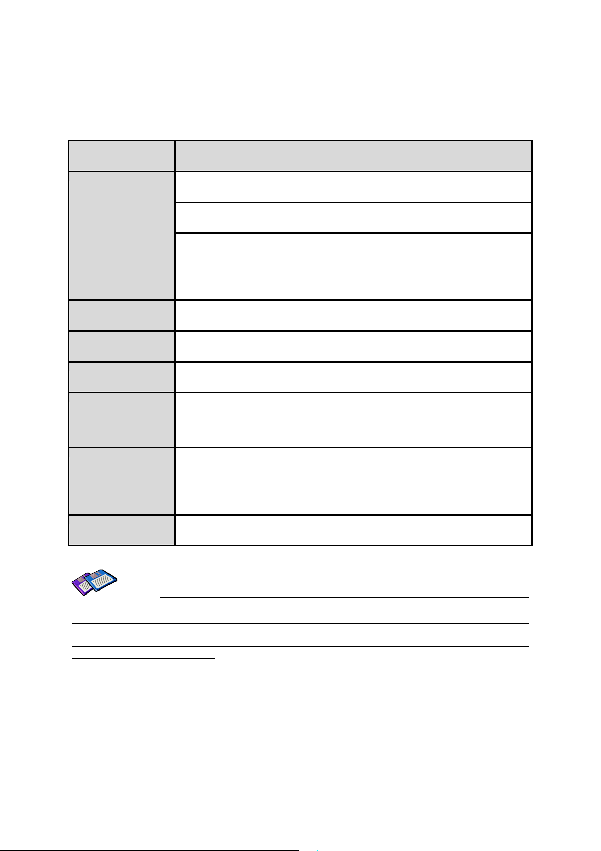
SD1000U has 4 operation modes as follows. Each mode can be identified with LED indicators as
illustrated in next section.
Table 2-1 SD1000U Operation Modes
Mode Description
Mode0
Mode1
Mode2
Mode3
In this mode, there is no response when power on or software reset, and SD1000U is just
waiting for AT command input. Neither master nor slave is assigned to Parani-SD1000 U in
mode0. User can change the configuration parameters of Parani-SD1000 in this mode.
SD1000U must be in Mode0, when it is directly controlled by AT commands.
The factory default is set to Mode0.
SD1000U tries to connect the last connected Bluetooth device.
SD1000U in Mode1 is to be a master and tries to connect the last connected Bluetooth device.
SD1000U always stores the BD address of the Bluetooth device to which SD1000U has
connected last. When Parani-SD1000 is initially used or after hardware reset, there is no BD
address stored in SD1000U. In this case, Mode1 will not be able to work properly. The mode
change to Mode1 can be made after SD1000U succeeds to connect to one other Bluetooth
device. Once changed to Mode1, SD1000U will try to connect automatically the last connected
Bluetooth device whenever the unit is powered on or software reset.
SD1000U in Mode1 cannot be discovered or connected by other Bluetoot h devices.
SD1000U is waits for a connection from the last connected Bluetooth device.
SD1000U in Mode2 is to be a slave and waiting for the connection only from the last
connected Bluetooth device. Just like Mode1, if there is no BD address stored in SD1000U,
the mode change from other operation modes to Mode2 is not work properly. Once changed to
Mode2, SD1000U will wait for the connection from the last connected Bluetooth device
whenever the unit is powered on or software reset.
SD1000U in Mode2 cannot be discovered or connected to Bluetooth devices other than the
last connected device.
SD1000U is waiting for the connection from any other Bluetooth devices. In Mode 3 the
SD1000U is discoverable and can be connected to by other Bluetooth devices.
2.3. LED Indicators
Serial-Tx and Serial-Rx LED will flash accordingly when data is transmitted. For small data
transmissions, it may be hard to recognize the quick flashing action of the LED.
TA
Page 12

02
Table 2-2 The SD1000U LED Indicators
Indicator Mode LED Connect LED
Mode 0
Mode 1
Mode 2
Mode 3
Connected
Green
┏━━━━━
Green
(every 1 sec) ┏┓
Green
(every 3 sec) ┏┰┓
Green
(every 3 sec) ┏┰┰┓
Green
2.4. Serial Ports
The applicable settings for serial ports are as follows.
Table 2-3 The SD1000U Serial Port Settings
Serial Port Settings
Baud rate
Data bite
Values
1200, 2400, 4800, 9600, 14400, 19200, 38400, 57600, 115200, 230400, 460800,
921600
8
(every 1 sec) ┏┓
Parity
Stop bit
Hardware Flow Control
No parity, Even parit y, Odd parity
1, 2
Use, No Use
The values in box are the factory defaults. The flow control setting is configurable only through dip
switch.
2.5. Data Bit
SD1000U supports only 8 data bit. In the case of 7 data bit and even/odd parity, use SD 8 data bit and
none parity. At this time, master and slave are Parani-SD, Parani-ESD or Parani-MSP series. But 7
data bit and none parity is not support.
2.6. Hardware Flow Control
SD1000U plugged into its host system transmits data from host to the other side Bluetooth device.
This data is saved temporarily in the internal buffer of SD1000U and sent repeatedly until the
transmission is completed packet by packet. When the radio transmission condition is not good
enough to send data promptly, it can cause a transmission delay. If the host sends more data when the
buffer is full, buffer overflow will make SD1000U malfunction consequently. In order to prevent this
buffer overflow, SD1000U works as follows.
When using hardware flow control, SD1000U disables RTS so that it stops receiving any further data
from the host when the buffer becomes full. RTS will be re-enabled again to begin receiving data from
the host when the buffer has created more room for more data.
TA
Page 13

02
When hardware flow control is not being used, the SD1000U clears the buffer to secure room for the
next data when the buffer becomes full. This can mean a loss of data may occur. As the transmission
data becomes large, the possibility of data loss becomes greater.
For large data transmissions, the use of hardware flow control is highly recommended.
2.7. Reset to Factory Defaults
To set all the configuration settings to its factory default parameters, press the reset button, depicted in
Fig. 3-1. Press and hold (for at least 1 sec) the reset button with a narrow pointed tool like paper clip.
Reset works only when power is on.
2.8. Dipswitch
With the combination of 4 slot dipswitches, baud rate and hardware flow control can be set.
Upper 3 dipswitches are used for setting the baud rate, and bottom dipswitch is used for setting
hardware flow control option. If the baud rate needs to a baud rate not shown below, ParaniWIN or
terminal program should be used to set these speeds. To set a baud rate not shown below the
dipswitches should be in the S/W Config setting. When in the S/W Config setting the baud rate will go
back to 9600 as default.
Table 2-4 Baud rate Settings by Dipswitches
2400 4800 9600 19.2K 38.4K 57.6K 115.2K S/W
baud rate
Config
Table 2-5 Hardware Flow Control Settings by Dipswitches
Hardware Flow Control
Handshaking
No Use Use
* Note: You cannot set the SD1000U to a Baud rate of 1200 and 230K by way of the Dipswitch. If you
want to use them, to set these speeds, please configure the dipswitch to S/W Config setting and use
ParaniWIN or AT commands. Please refer to ParaniWIN and Appendix 0 AT+UARTCONFIG, Baud
rate,Paraty,Stopbit.
TA
Page 14

02
2.9. Pairing Button
SD1000U provides Pairing Button for instant configuration without a PC to make an automatic
connection between two SD1000Us. In this example we will refer to the two SD1000Us as SD1 and
SD2. (Only single connection mode)
Step 1. Turn on SD1 and SD2 and reset both of them by pressing Factory Reset Button.
Step 2. Press the Pairing Button of SD1 for 2 seconds until Mode LED blinks 3 times every 3 seconds.
Keep the power ON.
Step 3. Press the Pairing Button of SD2 for 2 seconds until Mode LED blinks 3 times every 3 seconds.
Now press again the Pairing Button for 2 seconds until Mode LED blinks every second.
Step 4. Wait for SD1 & SD2 to connect to each other until the Connect LED’s of SD1 and SD2 blink
every 1 second. It takes about 10 seconds to make a connection. If there are many Bluetooth
devices nearby, it may take longer.
Step 5. Turn SD1 off and on. Mode LED blinks twice in green every 3 seconds.
Step 6. Turn SD2 off and on. Mode LED blinks in green every second.
Step 7. Now SD1 and SD2 are configured to make automatic connection to each other, whenever they
are powered on.
Using a pair of SD1000U in this fashion is similar to that of using a wireless serial cable.
* Note: When using the pairing buttons, the Command Response option will be deactivated
automatically. The SD1000U will not send the response messages such as OK, Connect and
Disconnect.
Table 2-6 Pairing Process by Pairing Button
SD1 Status LED SD2 Status LED
1. Factory reset Mode0 Mode LED turns on 1. Factory reset Mode0 Mode LED turns on
2. Push pairing
button
3. Push pairing
4. Connected Slave Connect LED blinks
Mode3 Mode LED blinks 3
times every 3 seconds
every second
2. Push pairing
button
button again
4. Connected Master Connect LED blinks
Mode3 Mode LED blinks 3
times every 3 seconds
Mode1 Mode LED blinks
every second
every second
Using pairing button, users can make a pairing connection between a Parani-SD unit and other
Bluetooth devices.
Step 1. Turn on SD1 and reset it by pressing Factory Reset Button.
Step 2. Press the Pairing Button of SD1 for 2 seconds until Mode LED blinks 3 times every 3 seconds.
Keep the power ON.
Step 3. Users can discover and connect to SD1 by using the software o r user in terface of other
Bluetooth device that they want to connect from.
Step 4. When they are connected, the Connect LED of SD1 blinks every 1 second.
Step 5. Turn off and on. Mode LED blinks twice in green every 3 seconds.
Step 6. Now SD1 is waiting for a connection from the last connected Bluetooth device. The last
connected Bluetooth device can connect to SD1.
Table 2-7 Pairing Process with other Bluetooth device by Pairing Button
SD1 Status LED Other Bluetooth Device Status
1. Factory reset Mode0 Mode LED turns on
TA
Page 15

02
2. Push pairin g button Mode3 Mode LED blinks 3 times
every 3 seconds
3. Inquiry and connect to SD1
4. Connected Slave Connect LED blinks
every second
4. Connected Master
2.10. Software and Utility
This configuration software and utility for firmware update is included with the product, which also can
be downloaded from http://www.sena.com
Table 2-8 Configuration Software
Software Purpose Operating System
ParaniWIN Configuration MS Windows 98SE or Higher
ParaniMultiWizard Multi Configuration MS Windows 98SE or Higher
ParaniUpdater Firmware Update MS Windows 98SE or Higher
2.11. ParaniWIN
ParaniWIN is a program that runs on Microsoft Windows for the configuration of SD1000U. Install
ParaniWIN on your computer. Plug a SD1000U into the serial port of the computer and turn on the
power. Run ParaniWIN.
Figure 2-1 Serial Port Setting
Set each option properly and click [Confirm]. If the settings of the SD1000U are different from the
ParaniWin, an error message will pop up. If the SD1000U is in the status of connection, warning
message will pop up. Then the current connection can be cancelled by [Disconnect] button on the
main window.
TA
Page 16

02
Figure 2-3 Main Window
Figure 2-4 Information Window
Serial port settings can be changed by <Start Configuration> and <ParaniWIN Configuration> of
ParaniWIN in the menu bar at upper left corner of the window without re-running the ParaniWIN
program.
TA
Page 17

02
Figure 2-5 Menu Bar at Upper Left corner of ParaniWIN
When the ParaniWin software is able to access the SD1000U properly, the icons in the left side
window come will become available for use.
In device configuration window, hardware reset can be executed or operation mode and RS232 can
be configured as well. Security option also can be configured in this window.
Figure 2-6 Device Setting Window
SD1000U supports two security options, Authentication and Encryption. If you enable the
Authentication option, you must also enter a Pin Code value. If the authentication is enabled, the
connection, between the Master and Slave device must share the same Pin Code. In case that
SD1000U connects to another Bluetooth device, that requires authentication, you must know the other
device’s Pin Code. In general, most Bluetooth devices have a pincode of 1234 or 0000. If you check
Encryption option, the SD1000U will encrypt packets and sent to the device. The Encryption options
works well in case that only one of the devices between Master and Slave use the Encryption option.
TA
Page 18

02
SD1000U has 4 response messages, ‘OK’, ‘ERROR’, ‘CONNECT’, and ‘DISCONNECT’. In some
cases, these responses can affect the host system unexpectedly. To prevent this, user can set the
Command response to ON or OFF.
For SD1000U, hardware flow control can be configured only by dip switch. And parity, stop bit can be
configured only SW config mode. Thus H/W Flow Control option will not work in this case. When the
dipswitch value isn’t ATcommand mode, the Baud Rate menu will be disabled.
Click [Apply] button to apply any changes made to the SD1000U.
Connection(out) icon will show the following window to search and connect other Bluetooth devices.
Figure 2-7 Connection (out) Window
Click [Search] button to search nearby Bluetooth devices. Once several Bluetooth devices has been
found, select one of the devices and click the [Connect] button. The selected Bluetooth device must be
discoverable and connectable. Click [Disconnect] button to cancel the connection.
After the connection has been established, you will be able to test signal strength by pushing the
START button.
TA
Page 19

02
Figure 2-8 Signal Strength Test
The signal strength test shows LInkQuality and RSSI values. The closer LinkQuality is to 255 and
RSSI is to 0, this means the SD1000U has a good connection to the connected Bluetooth device. In
general, the wireless connectivity is at its best within 10 meters. You can push the STOP button at
anytime in order to terminate the signal strength test. The signal strength test will continue until the
STOP button is pushed. If you close the ParaniWIN Window without pushing the STOP button, you
must restart SD1000U to terminate the test.
Connection(in) icon will show the following window, which enables the SD1000U to wait for a
connection from another Bluetooth device. If the waiting time is set to 0, SD1000U will continually wait
for connection until [Cancel] button is clicked.
TA
Page 20

02
Figure 2-9 Connection (in) Window
If the Connection Wizard icon is clicked, an easy to use pairing menu will app ear:
Figure 2-10 Connection Wizard Window
In this example we will refer to the two SD1000Us as SD1 and SD2 respectively. To use this menu,
please do the following:
TA
Page 21

02
Step 1. Connect SD1 and then push the START button.
Step 2. Disconnect SD1, connect SD2 and then push the Next button after setting up Slave
configuration. At this time, the dip switch value should be ATcmd mode. The flow control setting can
be changed only through dip switch.
Step 3. Disconnect SD2, once again connect SD1 and then push the Finish button. The pairing
configuration should be completed. Make sure that each SD1000U’s connect LED is on. At this point,
when both SD1000U’s restart the connection will be established automatically.
2.12. Parani Multi Wizard
Parani Multi Wizard is the software tool for multiple connection mode configurations of the Parani-SD
and Parani-ESD products.
Figure 2-11 Parani Multi Wizard Window
Parani Multi Wizard supports the Wizard mode and the Manual mode. The Wizard mode provide the
user step-by-step instructions for multiple mode configurations. To run the Wizard mode, select
“Multiple connection mode setting” and “1:N setting”, press “Start” button and follow the instructions.
TA
Page 22

02
Figure 2-12 Manual Setting Window
In the Manual mode, all settings for the multiple connection mode can be configured in one window. If
a Use field is unchecked or a slave address is entered as 000000000000, it is excluded from the Slave
settings.
The Auto Fill button will load the existing multiple connection mode settings from the Parani-SD/ESD
connected, which can be useful when only some parts of the settings are chang ed.
If the AT Command Response Disable check box is checked on, the AT command responses such as
OK, ERROR, CONNECT, DISCONNECT are suppressed.
2.13. ParaniUpdater
SD1000U supports firmware updates. You can download new firmware images for the SD1000U at
http://www.sena.com
the firmware image file and pushing Start button.
* Note: DO NOT power off SD1000U while the firmware update is progressing, this may damage the
SD1000U.
. With the ParaniUpdater, you can update the firmware of SD1000U by selecting
TA
Page 23

02
Figure 2-13 ParaniUpdater Window
2.14. Terminal Program
A terminal program is typically an application that will enable a PC to communicate directly with a
modem. If you are using Windows 98SE or higher version of Windows, HyperTerminal program is
included as part of the operating system. Parani-SD1000 provides some extended AT commands for
configuration of the SD1000U.
This manual will explain the method using HyperTerminal. If you need to install HyperTerminal, click
start>setting>control panel>add/remove programs. For more precise details on HyperTerminal
installations, please refer to Microsoft Windows Help section.
.
TA
Figure 2-14 HyperTerminal
Page 24

02
Attach SD1000U to serial port of host computer and power on the SD1000U. Check Mode LED. (See
3.2)
Make sure that the Connect LED is turned off and the Stanby LED is turned on before attempting to
send any kind of AT commands to the SD1000U. Then launch HyperTerminal, it can usually be found
in start >programs >accessories >communication >HyperTerminal. Select the Serial port that
SD1000U is connected to.
Select the Serial port setting in the window displayed, please make sure the serial settings in
Hyperterminal are set to the same settings as the SD1000U’s serial settings.
To view the AT commands that are being typed, you will need to enable the local echo option. Go to
File->Properties->Settings->ASCII setup and select the “Echo typed characters locally” option.
For expanded AT commands, please refer to Appendix A. AT commands.
Example of AT commands:
TA
Page 25

02
3. Multiple Connection Mode
3.1. Overview
SD1000U supports multiple connections up to 4 slave units. There are two types of multiple
connection modes: Multi-Drop Mode and Node Switching Mode.
Figure 3-1 Multi-Drop Mode
In Multi-Drop Mode a master unit can connect to maximum 4 slave units at the same time and they
transfer data bi-directionally as in Figure 3-1.
Figure 3-2 Node Switching Mode
In Node Switching Mode, the master unit maintains multiple connections with maximum 4 slave units
but only one connection with one slave unit is active and data is transferred as shown in Figure 3-2.
Active slave is selected by AT commands.
O
K
CONNECT 000195000001
Reset
31
TA
Page 26

02
3.2. Configuration
All the slaves should be in the status of waiting for connection either in Mode 2 or Mode 3 and the
master unit tries to connect to the slave units. The master unit needs to be configured to work in a
multiple connection mode using AT+MULTI,x command, which makes master reboots after execution.
Table 3-1 AT +MULTI,x
AT+MULTI,0
Single Connection Mode
AT+MULTI,1
AT+MULTI,2
Multi-Drop Mode
Node Switching Mode
Table 3-2 Configuration of a Multiple Connection Mode
Manual Connection Automatic Connection
ATD000195000001
CONNECT000195000001
+++
OK
ATD000195000002
CONNECT000195000002
+++
OK
ATD000195000003
CONNECT000195000003
+++
OK
ATD000195000004
CONNECT000195000004
+++
ATS46=000195000001
OK
ATS54=000195000002
OK
ATS55=000195000003
OK
ATS56=000195000004
OK
AT+MULTI,1 or AT+MULTI,2
OK
AT+BTMODE,1
After rebooted automatically
master tries to connect to
slaves
After input the BD addresses of the slave units into 4 S-registers S46, S54, S55 and S56 and then set
operation mode as MODE1, users can use multiple connection function. If S-registers have available
slaves’ address, AUTO CONNECT message will be displayed following corresponding TASK.
101 with stub antenna
at+btinfo?
00
TA
Page 27

02
3.3. AT Commands
3.3.1. AT+MULTI,n
Select a multiple connection mode. Refer to Table 4-1 for descriptions.
3.3.2. AT+MLIST?
It shows the current mode, the connection status and the BD addresses of slaves.
ting
+++
OK
ATO1 –
Comm
unic
atin
3.3.3. ATHx, ATHbdaddr
Using the ATH command, connections with all slaves or only connections with specific slaves can be
disconnected selectively
ATH
Table 3-3 ATH
Disconnect all the slaves.
A THx (ATH1, ATH2, ATH3, A TH 4)
ATHbdaddr (ATH000195000001)
Disconnect the slave which belongs to the TASK x.
Disconnect the slave with specified BD address.
3.3.4. ATOx, ATObdaddr
Using the ATO command, the communication status with the last active slave or a specific slave can
be set to online (only in Node Switching Mode).
Table 3-4 ATO
ATO
A TOx (ATO1, ATO2, ATO3, A T O4)
ATObdaddr (ATO000195000001)
TA
Communicate with the slave recently communicated.
Communicate with the slave which belongs to the TASK x.
Communicate with the slave with specified BDaddress.
Page 28

02
3.4. Notes
When large data exchange occurs in Multi-drop mode without flow-control enabled, the master unit
may experience data loss. It may also experience occasional disconnections and/or system rebooting
especially when bi-directional communication happens. It is strongly recommended to perform
extensive performance test before any real world field applications.
The master unit would try to connect all slave units specified by S-register 46, 54, 55 and 56. If nonexisting or inactive slave addresses are entered in these S-registers, the overall performance will
degrade due to frequent connection trials to non-existing/inactive slaves. It may also force
disconnections for overall performance and outputs disconnect messages repeatedly.
Node-switching mode provides nearly equivalent performance as single connection mode. It is always
recommended to use flow-control for both of Multi-Drop Mode and Node Switching Mode.
TA
Page 29

02
4. RF Information
4.1. Radio Frequency Range
2.402~2.480GHz
4.2. Number of Frequency Channel
79 channels
4.3. Transmission Method
FHSS (Frequency Hopping S pread Spectrum)
4.4. Modulation Method
GFSK (Gaussian-filtered Frequency Shift Keying)
Pi/4 DQPSK (pi/4 rotated Differential Quaternary Phase Shift Keying)
8DPSK (8 phase Differential Phase Shift Keying)
4.5. Radio Output Power
Products Radio Output Power
Parani-SD1000U +14dBm
4.6. Receiving Sensitivity
Products Receiving Sensitivity
Parani-SD1000U -88dBm
4.7. Power Supply
Products Power Supply
Parani-SD1000U USB 5.0V
TA
 Loading...