

Page 1

Parani-ESD100/110/200/210
User Guide
Version 1.0.0
2006-08-14
1
Page 2

User Guide for the Parani-ESD100/110/200/210
Version 1.0.0
Firmware version 1.0.X
Last revised on June 14, 2006
Printed in Korea
Copyright
Copyright 2002, Sena Technologies, Inc. All rights reserved.
Sena Technologies reserves the right to make changes and improvements to its product without
providing notice.
Trademark
Parani™ is a trademark of Sena Technologies, Inc.
Windows® is a registered trademark of Microsoft Corporation.
Ethernet® is a registered trademark of XEROX Corporation.
Notice to Users
When a system failure may cause serious consequences, protecting life and property against such
consequences with a backup system or safety device is essential. The user agrees that protection
against consequences resulting from system failure is the user's responsibility.
This device is not approved for life-support or medical systems.
Changes or modifications to this device not explicitly approved by Sena Technologies will void the
user's authority to operate this device.
Precautions and Safety
Electricity
Use only the supplie d AC a dapter . Use of un author ize d power ad apter is no t reco mm ended. Electr ica l
shock may result.
Do not kink or cr ease the po wer cab le or plac e he avy obj ects on th e po wer cab le. Fire c an resu lt fr om
damaged power cables.
Do not handle power plug and adapter with wet hands. Electrical shock may result.
Immediately power of f the pr oduct and u nplug the AC adapter if s m oke or odor s em it from the product
and adapter. Fire can result from improper use.
Immediately power off the produc t an d unp lu g the A C adap ter if water or other l iquids ar e pres e nt. Fire
can result from improper use.
Product
Parani-ESD meets th e RS-232 standards. Do not wire with non-standard produ cts. Damage to your
products may result from improper use.
Do not drop or subject the device to impact. Damage to your products may result from improper use.
Keep away from harsh environments including humid, dusty, and smoky areas. Damage to your
products may result from improper use.
Do not use excessive force on the buttons or attempt to disassemble the device. Damage to your
products may result from improper use.
Do not place heavy objects on the product. Damage to your products may result from improper use.
Technical Support
Sena Technologies, Inc.
210 Yangjae-dong, Seocho - gu
Seoul 137-130, Korea
Tel: (+82-2) 573-5422
Fax: (+82-2) 573-7710
E-Mail: support@sena.com
Website: http://www.sena.com
2
Page 3

Contents
1. Introduction 6
1.1. Overview ...................................................................................................................................6
1.2. Package Check List ...................................................................................................................6
1.3. Product Specification..................................................................................................................7
2. Getting Started 8
2.1. Panel Layout ..............................................................................................................................8
2.2. Connecting the Hardware ..........................................................................................................8
2.2.1. Connecting Parani-ESD to Jig Board ..............................................................................9
2.2.2. Connecting Power to Jig Board .......................................................................................9
2.2.3. Connecting a Device to Jig Board .................................................................................10
3. Configuration 11
3.1. Operation Modes......................................................................................................................11
3.2. Serial Ports...............................................................................................................................12
3.2.1. Data Bit ..........................................................................................................................12
3.2.2. Hardware Flow Control ..................................................................................................12
3.2.3. Software and Utility........................................................................................................12
3.2.4. ParaniWIN......................................................................................................................13
3.2.5. ParaniUpdater................................................................................................................19
3.2.6. Terminal Program ..........................................................................................................19
4. Approval Information 21
4.1. FCC .................................................................................................................................21
4.1.1. FCC Compliance Statement..........................................................................................21
4.1.2. RF Exposure Statement .................................................................................................21
4.1.3. Do not.............................................................................................................................21
4.2. CE .................................................................................................................................21
4.2.1. EC-R&TTE Directive......................................................................................................21
5. RF Information 22
5.1. Radio Frequency Range..........................................................................................................22
5.2. Number of Frequency Channel................................................................................................22
5.3. Transmission Method...............................................................................................................22
5.4. Modulation Method...................................................................................................................22
5.5. Radio Output Power.................................................................................................................22
5.6. Receiving Sensitivity ................................................................................................................22
5.7. Power Supply...........................................................................................................................23
Appendix A: Connections 24
A.1. Pin Assignment........................................................................................................................24
A.1.1. Parani-ESD100/110.......................................................................................................24
A.1.2. Parani-ESD200/210.......................................................................................................25
A.1.3. DCD Signal....................................................................................................................25
A.1.4. RST Signal.....................................................................................................................26
A.1.5. Pairing Signal (only for Parani-ESD100/110)................................................................26
A.2. Connection Diagram................................................................................................................27
A.2.1. Parani-ESD100/110.......................................................................................................27
A.2.2. Parani-ESD200/210.......................................................................................................29
Appendix B: AT Commands 31
B.1. Terminology..............................................................................................................................31
B.1.1. AT Command.................................................................................................................31
B.1.1. AT Response .................................................................................................................31
B.1.2. Operation Mode.............................................................................................................31
B.1.3. Operation Status............................................................................................................31
B.1.4. Security..........................................................................................................................31
B.1.5. Symbols.........................................................................................................................32
B.2. Command Category.................................................................................................................32
B.3. Command Description .............................................................................................................33
3
Page 4

B.3.1. ATZ ..............................................................................................................................33
B.3.2. AT&F ............................................................................................................................33
B.3.3. AT .................................................................................................................................33
B.3.4. AT+UARTCONFIG ,Baudrate,Parity ,S topbit,Hwfc ........................................................33
B.3.5. AT+USEDIP? ...............................................................................................................34
B.3.6. AT+BTINFO? ...............................................................................................................34
B.3.7. AT+BTINQ? ..................................................................................................................34
B.3.8. AT+BTLAST? ...............................................................................................................34
B.3.9. AT+BTVER? ................................................................................................................35
B.3.10. AT+BTRSSI,n ............................................................................................................35
B.3.11. AT+BTMODE,n ..........................................................................................................35
B.3.12. +++ .............................................................................................................................35
B.3.13. AT+SETESC,nn .........................................................................................................36
B.3.14. ATO ............................................................................................................................36
B.3.15. AT+BTCANCEL .........................................................................................................36
B.3.16. AT+BTSCAN ..............................................................................................................36
B.3.17. AT+BTSCAN,n,to .......................................................................................................37
B.3.18. AT+BTSCAN1 12233445566,to ..................................................................................37
B.3.19. ATD ............................................................................................................................37
B.3.20. ATD1 12233445566 ....................................................................................................38
B.3.21. ATH ............................................................................................................................38
B.3.22. AT+BTKEY=$string ....................................................................................................38
B.3.23. AT+BTSD? ................................................................................................................39
B.3.24. AT+BTCSD ................................................................................................................39
B.3.25. AT+BTFP,n
B.3.26. AT+BTSEC,Authentication,Encryption ......................................................................39
B.3.27. AT+BTNAME=$string ................................................................................................39
B.3.28. AT+BTLPM,n .............................................................................................................40
B.3.29. AT+DFU .....................................................................................................................40
B.3.30. AT&V ..........................................................................................................................40
B.3.31. ATSnn? .....................................................................................................................40
B.3.32. ATSnn=mm ................................................................................................................41
B.4. Command Validity....................................................................................................................41
.................................................................................................................39
Appendix C: S-Register 43
C.1. S1: Force to Reconnect (default 1)..........................................................................................43
C.2. S2: Enable Hardware Flow Control (default 1)........................................................................43
C.3. S3: Stream UART Policy (default 0)........................................................................................43
C.4. S4: Enable Remote Name Query (default 1)...........................................................................43
C.5. S6: Enable Low Power Mode (default 0).................................................................................44
C.6. S10: Enable SD Response (default 1) ....................................................................................44
C.7. S11: Enable Escape (default 1)...............................................................................................44
C.8. S12: Clear Data Buffer When Disconnected (default 0)..........................................................44
C.9. S14: Enable DTR Transfer (default 1) .....................................................................................44
C.10. S15: Enable Disconn ect by DTR (default 0)..........................................................................44
C.11. S22: Fast Connect (default 0)................................................................................................44
C.12. S24: Maximum Number of Inquiry Result (default 10) ..........................................................45
C.13. S28: Escape Sequence Character (default 43).....................................................................45
C.14. S31: Page Timeout (default 300)...........................................................................................45
C.15. S33: Inquiry Timeout (default 30) ..........................................................................................45
C.16. S37: Supervision Timeout (default 16000)............................................................................45
C.17. S46: BD Address of Last Connected Device.........................................................................45
Appendix D: Trouble Shooting 46
D.1 No Data Transmission ..............................................................................................................46
D.1.1 COM Port Settings .........................................................................................................46
D.2 Data Loss or Malfunctioning.....................................................................................................46
D.2.1Hardware Flow Control....................................................................................................46
4
Page 5

D.2.2 SD Response .................................................................................................................46
D.3 Transmission Delay ..................................................................................................................47
D.3.1 RF Processing Delay......................................................................................................47
D.3.2 RF Transmission Environment.......................................................................................47
Appendix E: How make a RS232 interface Jig Board 48
5
Page 6

1. Introduction
1.1. Overview
Parani-ESD is a m odule device f or wireless serial com munication us ing the Bluet ooth technolo gy that
is international standard of short range wireless communications. Parani-ESD accomplishes more
reliable wireless comm unication. As P arani-ESD c an comm unicate with oth er Blueto oth devices, user
may construct various communications with it.
Parani-ESD provides several models with different communication ranges from 30m (ParaniESD200/210) up to 100m (Parani-ESD100/110) for user’s various applications. In terms of noise,
Parani-ESD delivers better quality of communication than standard RS232 cables.
Parani-ESD has the m ost compact design of the sam e kind devices and can be placed convenientl y
into any devices or e qui pm ents. Its d etacha bl e a nte nn a of v ar iety optimizes the q ual ity and distance of
wireless communications.
Parani-ESD can be configured and controlled by typical AT commands. User can easily configure
Parani-ESD on the terminal program such as HyperTerminal and implements the wireless
communication without modifying user’s existing serial communication program. In addition to the
basic AT commands, Parani-ESD provides som e expanded AT comm ands for its various functions.
User friendly ParaniWizard and ParaniWIN are also provided for easy setup on Microsoft Windows.
The FHSS (Frequenc y Hopping Spread Spectrum) techniq ue of Bluetooth lets Parani-ESD h ave less
radio interference and no danger of hack ing in air. Parani-ESD also supports aut hentication an d data
encryption.
1.2. Package Check List
- Parani-ESD100/110/200/210
- A hardcopy of
- CD-ROM including the HelloDevice Manager and User Guide
Quick Start Guide
6
Page 7

1.3. Product Specification
ESD100/110 ESD200/210
Serial Interface
Bluetooth Interface
Serial speeds 1200bps to 230400bps
Flow Control: None, Hardware RTS/CTS
2.54mm Header 2X6 2.54mm Header 1X4X2
Bluetooth v1.2
Protocol: RFCOMM, L2CAP, SDP
Profile: General Acc es s Profile, Ser i al Por t Pr of il e
Class 1 Class 2
Level: 18dBm Level: 2dBm
ESD100-Working distance:
Nominal 100m
ESD110-Working distance:
Up to 100m
ESD210-Working distance:
Nominal 30m
ESD210-Working distance:
Up to 30m
Configuration
Firmware Update
Power
Environmental
Physical properties
Approvals
Warranty
ParaniWIN, ParaniWizard, Modem AT command set
ParaniUpdater for SD&ESD
Supply voltage: DC3.3V
Operating temperature: -20 ~ 70
Humidity : 95% (Non-condensing)
Dimension
- ESD100
27.5 mm L (1.08 in.)
27.7 mm W (1.09 in.)
14.0 mm H (0.55 in.)
- ESD110
27.5 mm L (1.08 in.)
30.0 mm W (1.18 in.)
14.0 mm H (0.55 in.)
Weight
5 g
FCC, MIC
1-year limited warrant y
o
C
Dimension
- ESD200
- ESD210
Weight
18.0 mm L (0.7 in.)
20.0 mm W (0.78 in.)
11.7 mm H (0.47 in.)
18.0 mm L (0.7 in.)
20.0 mm W (0.78 in.)
11.7 mm H (0.47 in.)
2 g
7
Page 8
2. Getting Started
This chapter describes how to set up the Parani-ESD Series for the first time.
- 2.1 Panel Layout explains the panel layout.
- 2.2 Conn ecting the Hardware descr ibes how to connect the Paran i-ESD Series, the power, a nd the
serial device to the Jig Board.
Following items are pre-required to get started.
- One Jig Board (included in the Starter Kit package).
- One DC power adapter or one USB power cable (included in the Starter Kit package).
- One serial console cable for configuration (included in the Starter Kit package).
- One PC with RS232 serial port.
- Terminal emulation program running on the PC
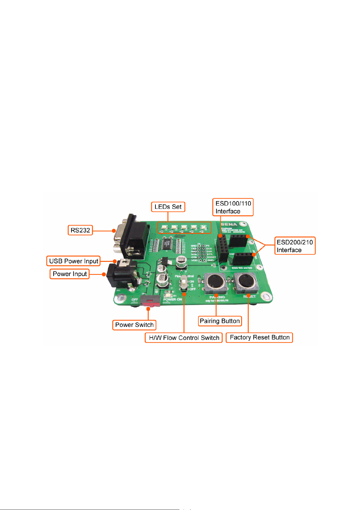
2.1. Panel Layout
This section describes the panel layout of the Jig Board.
Figure 2-1 The panel layout of Jig Board
2.2. Connecting the Hardware
This section descr ibes how to connect the Par ani-ESD Series to the Jig Boar d and the Jig Board to
the serial device for initial testing.
- Connect the Parani-ESD Series to Jig Board.
- Connect a power source to Jig Board for the Parani-ESD Series.
- Connect Jig Board for the Parani-ESD Series to a serial device.
8
Page 9
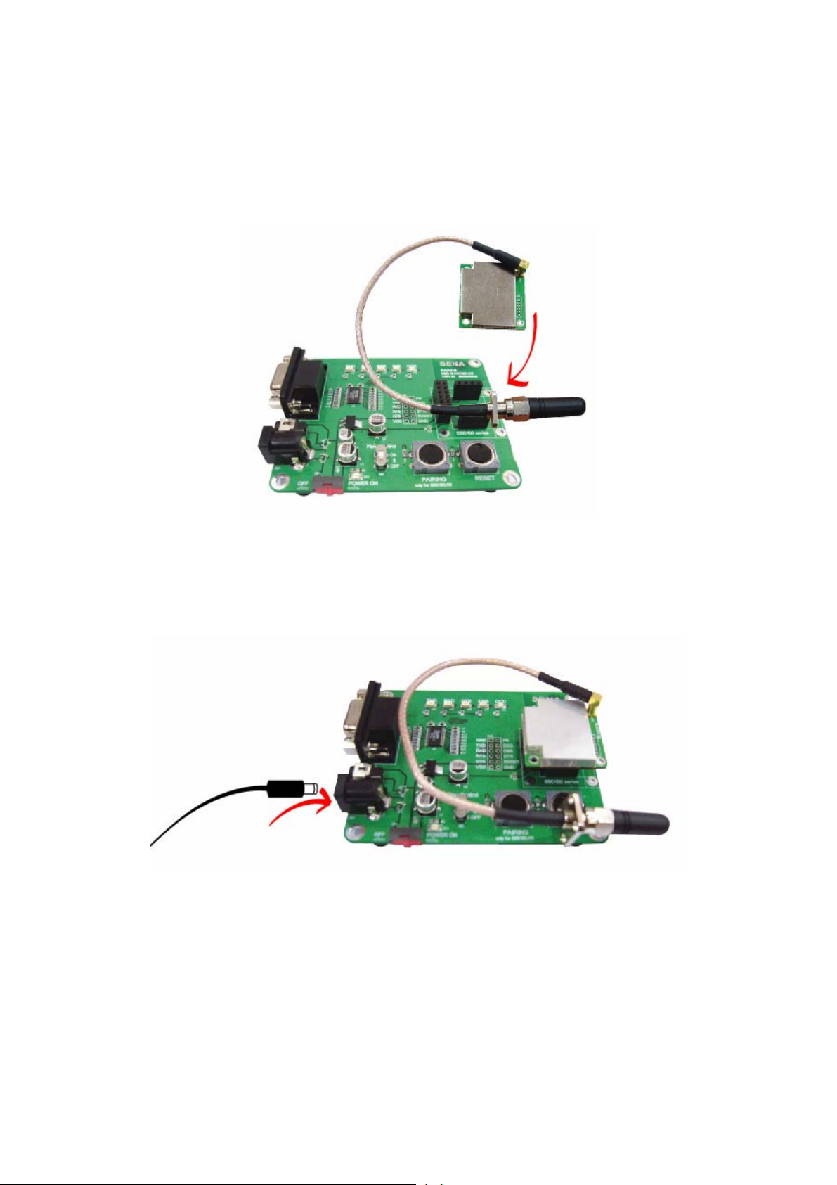
2.2.1. Connecting Parani-ESD to Jig Board
Connect the Parani-ESD Series to the Jig Board as shown below.
Figure 2-2 Connecting Parani-ESD to Jig Board
2.2.2. Connecting Power to Jig Board
Connect the power jac k to the power c onnector of the Jig Board for the Parani-ESD Ser ies using the
DC power adapter or USB power cable that is included in the package.
Figure 2-3 Connecting Power to Jig Board
9
Page 10
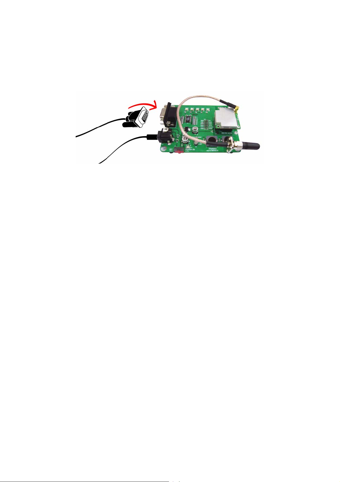
2.2.3. Connecting a Device to Jig Board
Connect the serial data c able between the Jig Board and the serial device. If neces sary, s upply the
power to the serial device attached to the Jig Board.
Figure 2-4 Connecting a Device to Jig Board
10
Page 11

3. Configuration
3.1. Operation Modes
In addition to the s erial port configuratio ns such as bit/second, data b it, parity, stop bit, flow co ntrol,
Parani-ESD has some configurations for Bluetooth. For getting the most out of Parani-ESD, user
should understand the following Bluetooth connection schemes.
A Bluetooth device can play a role as a master or slave. Master tries to connect itself to other
Bluetooth device, and slave is waiting to be connected from other Bluetooth devices. A Bluetooth
connection is al ways made b y a pair of m aster and sl ave. A slave can be in t wo modes , Inquiry Scan
or Page Scan m ode. Inquiry Sc an mode is waiting the pack et of inquir y from other Bluet ooth devices
and Page Scan mode is waiting the packet of connection from other Bluetooth devices. Every
Bluetooth device h as its uni que ad dress , calle d BD ( Bl uetooth Device) ad dress , whic h is com posed of
12 hexa-decimal numbers.
Parani-ESD has 4 oper ation modes as follows. Eac h mode can be identified with LED indicators as
illustrated in next section.
Table 3-1 The Parani-ESD Operati on Mod es
Mode Description
Mode0
Mode1
Mode2
Mode3
Parani-ESD must be in Mode0, when it is directly controlled by AT commands.
In this mode, there is no response when power on or software reset, and Parani-ESD is just
waiting for AT command input. Neither master nor slave is assigned to Parani-ESD in mode0.
User can change the configurations of Parani-ESD in this mode.
The factory default is set to Mode0.
Parani-ESD tries to connect the last connected Bluetooth device.
Parani-ESD in Mode1 is to be a master and tries to connect the last connected Bluetooth
device. Parani-ESD always stores the BD address of the Bluetooth device to which ParaniESD has connected last time. When Parani-ESD is initially used or after hardware reset, there
is no BD address stored in Parani-ESD. In this case, Mode1 does not make any sense and
mode change from other operation modes to Mode1 is not allowed. The mode change to
Mode1 can be made after Parani-ESD succeeds to connect to other Bluetooth device in
Mode0. Once changed to Mode1, Parani-ESD will try to connect automatically the last
connected Bluetooth device whenever power on or software reset.
Parani-ESD in Mode1 cannot be discovered or connected by other Bluetooth devices.
Parani-ESD is waiting for the connection from the last connected Bluetooth device.
Parani-ESD in Mode2 is to be a slave and waiting for the connection only from the last
connected Bluetooth device. Just like Mode1, if there is no BD address stored in Parani-ESD,
the mode change from other operation modes to Mode2 is not allowed. Once changed to
Mode2, Parani-ESD will wait for the connection from the last connected Bluetooth device
whenever power on or software reset.
Parani-ESD in Mode2 cannot be discovered or connected to Bluetooth devices other than the
last connected device.
Parani-ESD is waiting for the connection from any other Bluetooth devices.
Parani-ESD in Mode3 acts like in Mode2, but allows any connection from other Bluetooth
device. Most of general Bluetooth device is set to Mode3.
Parani-ESD in Mode3 can be discovered and connected from any other Bluetooth devices.
11
Page 12

3.2. Serial Ports
The applicable settings for serial ports are as follows.
Table 3-2 The Parani-ESD Seri al Por t Sett in gs
Serial Port Settings Values
Baud rate
Data bite
Parity
Stop bit
Hardware Flow Control
1200, 2400, 4800, 9600, 19200, 38200, 57600, 115200, 230400
8
No parity, Even parity, Odd parity
1, 2
Use, No Use
The values in box ar e the factory defaults. The flow contr ol setting is configurable only thro ugh dip
switch.
3.2.1. Data Bit
Parani-ESD supports only 8 data bit. In the case of 7 data bit, please contact the technical support.
3.2.2. Hardware Flow Control
Parani-ESD plugg ed into its host system transmits data from host to t he other side Bluetooth device.
These data is saved temporarily in the internal buffer of Parani-ESD and sent repeatedly until the
transmission is completed packet by packet. When the radio transmission condition is not good
enough to send data prom ptly, it can cause the transm ission dela y. If the host sends more data when
the buffer is full, buffer ove rflow will make Parani-E SD malfunction conseq uently. In order to prevent
this buffer overflow, Parani-ESD works as follows.
In case of using har dware flow control, Parani-ESD mak es RTS be ‘disable’ to stop receiv ing further
data from the host when the buffer becom es full. RTS will be ‘a ble’ to begin receiving data again f rom
the host when the buffer has some room for more data.
In case of not using hard ware flow control, Paran i-ESD clears the buffer to s ecure the room for next
data when the buffer becom es full. This means the l oss of data. As the transmiss ion data becomes
large, the possibility of data loss goes higher.
For large data transmission, use of hardware flow control is highly recommended.
3.2.3. Software and Utility
This configuration software and uti lity for firm ware update c omes with the product, wh ich also can be
downloaded from http://www.sena.com
Table 3-3 Configuration Software
Software Purpose Operating System
ParaniWIN Configuration MS Windows 98SE or Higher
ParaniWizard Pairing Configuration
ParaniUpdater Firmware Update MS Windows 98SE or Higher
12
Page 13
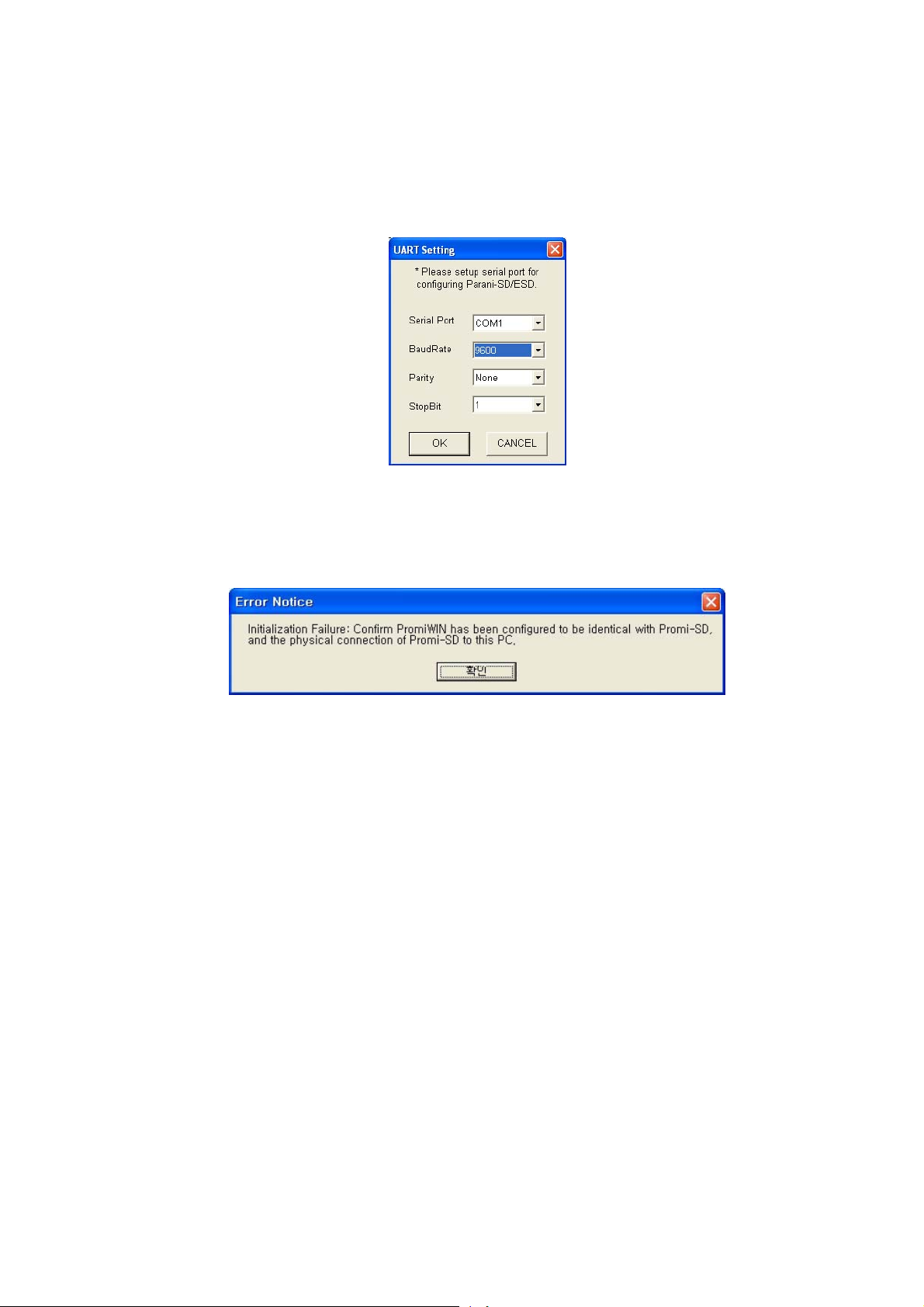
3.2.4. ParaniWIN
ParaniWIN is a program running on Microsoft Windows for the configuration of Parani-ESD. Install
ParaniWIN on your computer. Plug a Parani- ESD into the s erial port of the computer and turn on t he
power. Run ParaniWIN.
Figure 3-1 Serial Port Setting
Set each option properl y and click [Confirm]. If the settings are differ ent from the host c omputer, error
message will pop up. If the Parani-ESD is in t he status of connection, warning message will po p up.
Then the current connection can be cancelled by [Disconnect] button on the main window.
Figure 3-2 Error Message Box
13
Page 14
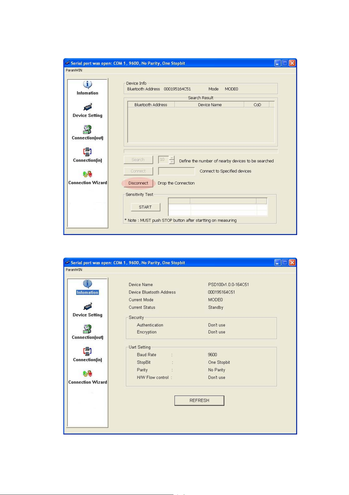
Figure 3-3 Main Window
14
Page 15
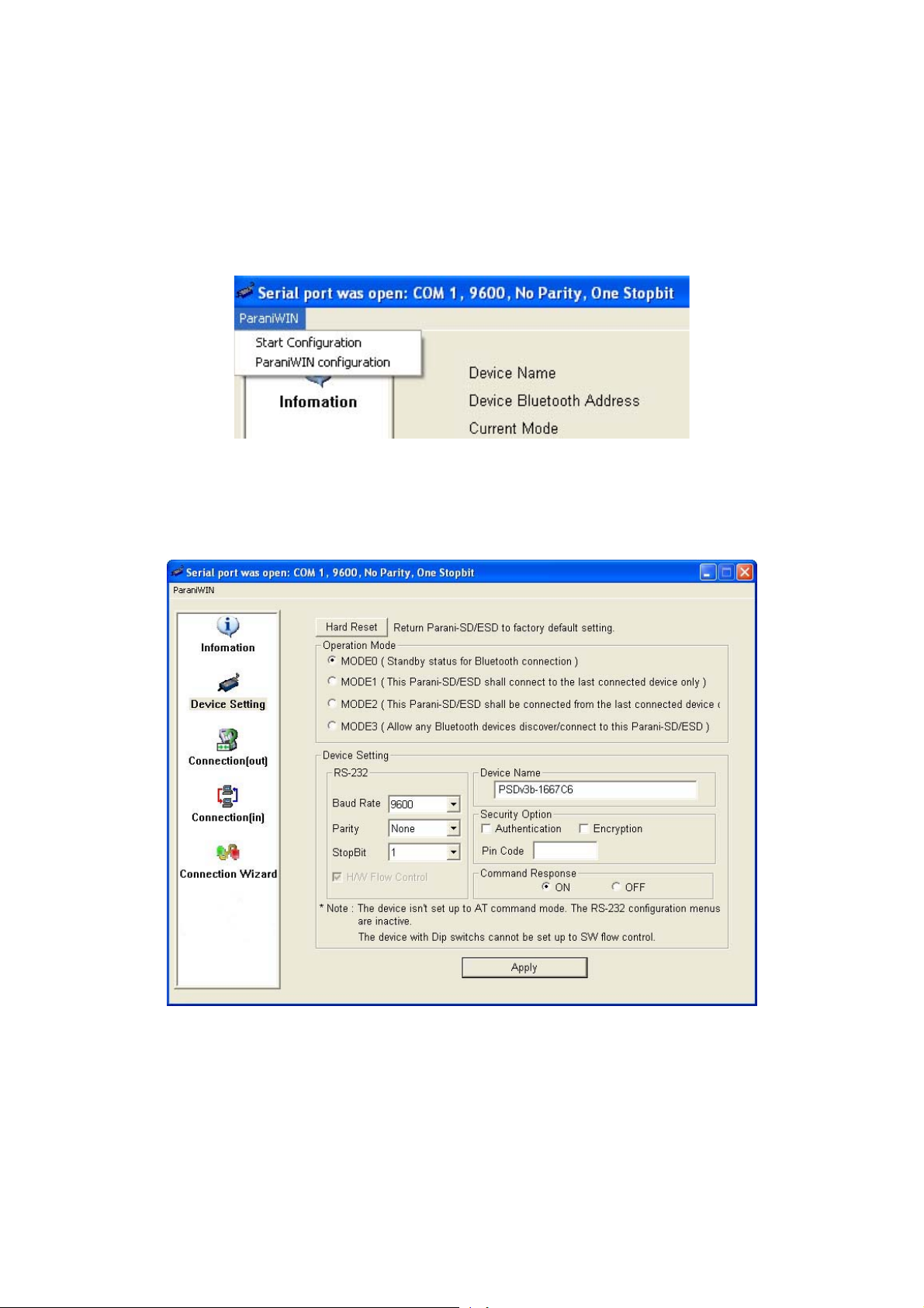
Figure 3-4 Information Window
Serial port settings can be changed by <Start Configuration> and <ParaniWIN Configuration> of
ParaniWIN in the menu bar at upper left corner of the window without re-running the ParaniWIN
program.
Figure 3-5 Menu Bar at Upper Left corner of ParaniWIN
The icons in the left side window come to the corresponding windows.
In device configurat ion window, hardware reset can be ex ecuted or operation m ode and RS232 can
be configured as well. Securit y option als o can be confi gur ed in this win do w.
Figure 3-6 Device Setting Window
Parani-ESD supports two security options, Authentication and Encryption. If you check the
Authentication op tion, you must also ent er the Pin Code valu e. If the authenticatio n is activated, the
connection, onl y between the Master and Slave dev ice that sh are the sam e Pin Code, is establish ed.
In case that Parani-ESD connects to other Bluetooth device that enables authentication, you must
know the other device’s Pin Code. In general Bluetooth devic es, 1234 or 0000 is used as a defaul t
15
Page 16

value. If you check Encryption option, the Parani-ESD encrypts packets and sends them. The
Encryption options works well in case that only one between Master and Slave uses this option.
Parani-ESD has 4 resp onse messages, ‘OK’, ‘ERROR’, ‘CO NNECT’, and ‘DISCONNECT’. In som e
cases, these responses can affect the host system unexpectedly. To prevent this, user can set the
Command response to ON or OFF.
Click [Apply] button to reflect the given options to Parani-ESD actually.
Connect(out) icon will show the following window to search and connect other Bluetooth devices.
Figure 3-7 Connect(out) Window
Click [Search] button to search nearby Bluetooth devices. The maximum number of devices to be
searched can be controlled. Select one of the devices searched and click [Connect] button. The
selected Bluetooth device must be in Page scan mode. Click [Disconnect] button to cancel the
connection normally.
After the connection is established, you are able to test sensitivity by pushing the START button.
16
Page 17

Figure 3-8 Sensitivity Tes t
The sensitivity test shows LInkQuality and RSSI values. The sensitivity is fine, If the LinkQuality is
closer to 255 and RSSI is c loser to 0. In general, the sensitivit y is the best when the distance is 10
meters. You can push the ST OP button in order t o terminate the sensiti vit y tes t. The sensitivity test will
continue until the STOP button is pushed. If you close the ParaniW IN Window without pushing th e
STOP button, you must restart Parani-ESD to terminate the test.
Connection(in) icon will sh ow the foll owing win dow to mak e Parani-ESD wait to a connec tion fr om the
other Bluetooth devic e. The waiting time in seconds can be controlled. With 0 input for this waiting
time, Parani-ESD keeps waiting for connection until [Cancel] button is clicked.
17
Page 18

Figure 3-9 Connection(in) Window
If the Connection Wizard icon is clicked, an easy pairing menu to use appears as follows:
Figure 3-10 Connection Wizard Wind ow
18
Page 19

This menu make easy pairing configuration of Parani-ESD. To use this menu, follow next steps.
Step 1. Connect the first ESD and then push the START button.
Step 2. Disconnect the f irs t ESD, c o nnect the second ESD an d t hen p us h t he Ne xt butt on after s etti ng
up Slave configuration.
Step 3. Disconnect the second ESD, once again connect the first ESD and then push the Finish
button. The pairing conf iguration finis hed. From no w, when the ESD restarts the pairing connect ion
will be established automatically.
3.2.5. ParaniUpdater
Parani-ESD support firmware update. You can download new firmwares of Parani-ESD at
http://www.sena.com
firmware image file and pushing Start button.
* Note: DO NOT power off Para ni-ESD while t he firmware update is progressing. It m ay damage the
firmware seriously.
. With ParaniUpdater, you can u pdate firmware of Parani-ESD by selecting the
Figure 3-11 ParaniUpdater Window
.
3.2.6. Terminal Program
A terminal program is an appl ication that will enable a PC to communicate dir ectly with a m odem. If
you are using Windo ws 98SE or higher versio n of Windows, HyperTerminal program as it is includ ed
as part of the operating system. Parani-ESD provides some extended AT commands for its
configurations on terminal program.
This manual will exp lain the method using Hyper Terminal. If you need to install HyperTerminal, click
start>setting>control pane l>add/remove pr ograms . For more precise information, ple ase refer to Hel p
of Microsoft Windows.
Attach Parani-ESD to serial port of host computer and power on.
19
Page 20

Launch HyperTerminal. It can be found in start >programs >accessories >communication
>HyperTerminal. Select the Serial port t hat Para ni-ESD will be connected to.
Input the same settings into Serial port configuration window as Parani-ESD settings.
The settings need to be set correctly, otherwise, err or message may be shown up on the screen or
cause malfunctioning of Parani-ESD.
Figure 3-12 HyperTreminal
Choose the settings in File->Properties->Settings->ASCII setup that let you turn echo on in
HyperTerminal; this will show the response Parani-ESD sends on the screen.
You now get the HyperTerminal window where you are able t o c ontrol Parani-ESD with AT commands.
For expanded AT commands that Parani-ESD provides, please refer to Appendix A. AT commands.
Example of AT commands:
AT+BTINFO?
000B53000509,PSDv3b-000509,MODE0,STANDBY,0,0,HWFC
OK
AT+BTINQ?
000B5320007E,PSDv2a-20007E,001F00
0004B300E205,AP2002:1 #0,020300
OK
ATD000B53000509
OK
CONNECT 000B53000509
20
Page 21

4. Approval Information
4.1. FCC
4.1.1. FCC Compliance Statement
This device complies with part 15 of the FCC Rules. Operation is subject to the following two
conditions:
(1) This device may not cause harmful interference, and
(2) This device must accept any interference received,
Including interference that may cause undesired operation
Information to User
This equipment has been t ested and found to com ply with the l imits f or a Class B digital device,
Pursuant to part 15 of the FCC Rules. These limits are designed to provide reasonable
protection against harmful interference in a residential installation.
This equipment generates, uses and can radiate radio Frequency energy and, if not installed
and used in accordance with the instructions, may cause harmful interference to radio
communications.
However, there is no guarantee that interference wil l not occur in a particular installation. If this
equipment does cause harmful interference to radio or television reception, which can be
determined by turning the equipment off and on, the user is encouraged to try to correct the
interference by one or more of the following measures:
- Reorient or relocate the receiving antenna.
- Increase the separat ion b etween the equipm ent a nd rec eiv er- Con nec t the eq ui pment into an
outlet on a circuit different from that to which the receiver is connected.
- Consult the dealer or an experienced radio/TV technician for help.
4.1.2. RF Exposure Statement
The equipment complies with FCC RF radiation exposure limits set forth for an uncontrolled
environment. T his device and its ante nna must not be c o-located or operati on in conjunction with
any other antenna or transmitter.
4.1.3. Do not
Any changes or modifications to the equ ipment not expressl y appro v ed b y the par t y respo nsib le f or
compliance could void user’s authority to operate the equipment.
4.2. CE
4.2.1. EC-R&TTE Directive
EN 50385
EN 60950
EN 301 489-1/-17
EN 300 328
21
Page 22

5. RF Information
5.1. Radio Frequency Range
2.402~2.480GHz
5.2. Number of Frequency Channel
79 channels
5.3. Transmission Method
FHSS(Frequenc y Hopping Spread Spectrum)
5.4. Modulation Method
GFSK(Gaussian-filtered Frequency Shift Keying)
5.5. Radio Output Power
Products Radio Output Power
ESD100 +18dBm
ESD110 +18dBm
ESD200 +4dBm
ESD210 +4dBm
5.6. Receiving Sensitivity
Products Radio Output Power
ESD100 -88dBm
ESD110 -88dBm
ESD200 -80dBm
ESD210 -80dBm
22
Page 23

5.7. Power Supply
Products Radio Output Power
ESD100 DC3.3V
ESD110 DC3.3V
ESD200 DC3.3V
ESD210 DC3.3V
23
Page 24

Appendix A: Connections
A.1. Pin Assignment
A.1.1. Parani-ESD100/110
Figure A-1 Pin Assignment of Parani- ESD 10 0/1 10
Table A-1. Pin Assignment of Parani-ESD100/110
Pin # Signal Direction Description Signal Level
1
2
3
4
5
6
7
8
9
10
11
GND - Power Ground Ground
TxD Output UART Data Output TTL
RxD Input UART Data Input TTL
RTS Output UART Ready to Send TTL
CTS Input UART Clear to Send TTL
VDD Input DC Input (3.0~3.3V) Ground
Pairing Input Pairing Input TTL
Status Output Bluetooth Connect Detect (Active Low) TTL
DSR Input Data Set Ready TTL
DTR Output Data Terminal Ready TTL
RST Input Reset (Active Low) TTL
12
GND - Power Ground Ground
24
Page 25

A.1.2. Parani-ESD200/210
Antenna
1
2
3
4
Figure A-2 Pin Assignment of Parani- ESD 20 0/2 10
Table A-2 Pin Assignment of Paran i- ESD 20 0/2 10
Pin # Signal Direction Description Signal Level
1
GND - Power Ground Ground
5
6
7
8
2
3
4
5
6
2
3
VDD Input DC Input (3.0~3.3V) Ground
Status Output Bluetooth Connect Detect (Active Low) TTL
RST Input Reset (Active Low) TTL
CTS Input UART Clear to Send TTL
RTS Output UART Ready to Send TTL
TxD Output UART Data Output TTL
RxD Input UART Data Input TTL
A.1.3. DCD Signal
Status of Bluetooth connection will be delivered to Host PC via DCD line. When Bluetooth
connection is m ade, DCD signal will be in state OFF. For disconnection of Bl uetooth, DCD signal
will become state ON.
Connection Module Æ low signal
25
Page 26

A.1.4. RST Signal
RST signal will be used f or initializatio n of Parani-ESD. RST should be on 0V status f or at least 1
second for this.
A.1.5. Pairing Signal (only for Parani-ESD100/110)
Parani-ESD100/110 provides pairing sign al input for instant configurat ion without PC to make an
automatic connecti on between two Parani-ESDs . For convenience sake, nam e two Parani-ESDs
as ESD1 and ESD2 respectively.
Step 1. Turn off all the nearby Parani-ESD
Step 2. Turn on ESD1 and ESD2 and hardware reset both of them by using RST signal.
Step 3. Drop the pairing signal of ESD1 to low state and keep it for 2 seconds. Keep the power ON.
Step 4. Drop the pairing signa l of ESD2 to low state and k eep it for 2 seconds. Rais e the pairing
signal of ESD2 to high state and keep it for 2 seconds. Now drop again the pairing signal of
ESD2 to low state and keep it for 2 seconds
Step 5. Wait for ESD1 & ESD2 to be c onnected for a while. It takes about 10 seconds to m ake a
connection. If there are many Bluetooth devices nearby, it will take a little bit more.
Step 6. Now a pair of Parani-SD is configured to m ake automatic conn ection, whenever p ower off
and on.
Just use this pair of Parani-SD like virtual serial cable.
* Note: While pairing is progressing by the pairing signal, the Command Response will be
inactivated automatically. Then, Parani-ESD will not send the response messages such as OK,
Connect and Disconnect.
Table 0-1 Pairing Process by Pairing Signal
ESD100/110 Status Pairing Signal ESD200/210 Status Paring Signal
1. Hard reset Mode0 HIGH 1. Hard reset Mode0 HIGH
2. Drop pairing
signal
Mode3 LOW 2. Drop pairing
signal
Mode3 LOW
3.Restore
pairing signal
4. Drop pairing
5.Restore
6. Connected Slave HIGH 6. Connected Master HIGH
Mode3 HIGH 3.Restore
pairing signal
signal
pairing signal
Mode3 HIGH
Mode1 LOW
Mode1 HIGH
26
Page 27

A.2. Connection Diagram
A.2.1. Parani-ESD100/110
A.2.1.1. When TTL level of MICOM is 3.3V
MICOM
MICRO-VDD
MICOM-DCD
MICOM-TXD
MICOM-RXD
MICOM-RTS
MICOM-CTS
MICOM-DTR
MICOM-DSR
MICOM-RST
MICOM-GND
DC 3.3V
PROMI-ESD01
VDD
Status
RXD
TXD
CTS
RTS
DSR
DTR
RST
GND
A.2.1.2. When TTL level of MICOM is 3.3V and Hardware Flow Control is not used
27
Page 28

A.2.1.3. When TTL level of MICOM is 5V
MICOM
MICRO-VDD
MICOM-DCD
MICOM-TXD
MICOM-RXD
MICOM-RTS
MICOM-CTS
MICOM-DTR
MICOM-DSR
MICOM-RST
MICOM-GND
DC 3.3V
68K 115K
68K 115K
68K 115K
68K 115K
PROMI-ESD01
VDD
Status
RXD
TXD
CTS
RTS
DSR
DTR
RST
GND
28
Page 29

A.2.2. Parani-ESD200/210
A.2.2.1. When TTL level of MICOM is 3.3V
A.2.2.2. When TTL level of MICOM is 3.3V and Hardware Flow Control is not used
29
Page 30

A.2.2.3. When TTL level of MICOM is 3.3V and Hardware Flow Control is not used
30
Page 31

Appendix B: AT Commands
B.1. Terminology
B.1.1. AT Command
AT command set is the
developed by
HTHayesTH and is recognized by virtually all HTpersonal computerTH modems. Parani-ESD
HTde facto standardTH HTlanguageTH for control ling HTmodemsTH. The AT command set was
provides the extended AT command set to control and configur e the serial parameter s and Bluetooth
connection.
B.1.1. AT Response
Parani-ESD replies to AT commands with 4 kinds of message, ‘OK’, ‘ERROR’, ‘CONNECT’ and
‘DISCONNECT’.
B.1.2. Operation Mode
Mode Description
Mode0
Mode1
Mode2
Mode3
Waiting for AT commands
Attempting to connect the last connected Bluetooth device
Waiting for the connection from the last connected Bluetooth device
Waiting for the connection from any other Bluetooth device
B.1.3. Operation Status
Status Description
Standby
Pending
Connect
Waiting for AT commands
Executing tasks
Executing tasks
B.1.4. Security
Security Description
Authentication
Encryption
Pin Code (or Pass key)
Data encryption
31
Page 32

B.1.5. Symbols
The symbols are used for the description of command syntax as follows:
Symbols Meaning ASCII Code
N or m One digit decimal number
to Timeout in seconds
Carriage return 0x0D
Line feed 0x0A
Carriage return + Line feed
Bluetooth device address
B.2. Command Category
Command Category Index AT Commands
RESET 1
SERIAL PORT 3
BLUETOOTH
Information 6
2
4
5
7
8
ATZ
AT&F
AT
AT+UARTCONFIG,b,p,s,h
AT+USEDIP?
AT+BTINFO?
AT+BTINQ?
AT+BTLAST
Mode 9 AT+BTMODEn
Status 10
11
12
13
14
15
16
Connection 17
18
19
Security 20
21
22
23
24
Miscellaneous 25
26
S-REGISTER 27
28
29
+++
AT+SETESC,nn
ATO
AT+BTCANCEL
AT+BTSCAN
AT+BTSCAN,n,to
AT+BTSCAN112233445566,to
ATD
ATD112233445566
ATH
AT+BTKEY=$string
AT+BTSD?
AT+BTCSD
AT+BTFP,n
AT+BTSEC,a,e
AT+BTNAME=$string
AT+BTLPM,n
AT&V
ATSnn?
ATSnn=mm
32
Page 33

B.3. Command Description
B.3.1. ATZ
SD Response
Purpose
Description
Reference
B.3.2. AT&F
SD Response
Purpose
Description
Reference
B.3.3. AT
OK
Software Reset
This is the same effect as power off and on.
This command disconnects B l uetoot h devi ce, and sto p s ong oing task. After rebooting, the
status is decided by the preset operation mode.
Some AT commands need ATZ to take effect.
A T&F, AT+BTCSD, AT+UARTCONFIG
OK
Hardware reset
This is the same effect as initialization by reset button.
All parameters are initialized to factory defaults. The storage of Parani-ESD is cleared
completely.
ATZ
SD Response
Purpose
Description
Reference
OK
Check the connection status with host equipment
Check if the connection to host equipment is normal. The serial parameters of Parani-ESD
must be same as those of host equipment. If not, SD response is none or ‘ERROR’ or
abnormal sequence of strings.
AT+UARTCONFIG, ATZ, AT&F
B.3.4. AT+UARTCONFIG,Baudrate,Parity,Stopbit,Hwfc
SD Response
Purpose
Parameters
Description
Reference
Example
OK
Set Serial parameters
Baudrate=1200/2400/9600/14400/19200/38400/57600/115200/230400 (Default=9600)
Parity=N/E/O (Default=N)
Stopbit=1/2 (Default=1)
Hwfc(Hardware Flow Control)=0/1 (Default=1)
The Serial parameters can be set or changed. The factory default is 9600, N, 1.
To take effect of this command, ATZ or power off and on.
AT, ATZ, AT&F, ATS
AT+UARTCONFIF,9600,N,1
33
Page 34

B.3.5. AT+USEDIP?
SD Response
Purpose
Description
Reference
m
Check the Baud rate set by dip switch
m=0: Set to ‘AT cmd’
m=1: Set to other than ‘AT cmd’
AT, ATZ, AT&F, ATS
B.3.6. AT+BTINFO?
SD Response
Purpose
Description
112233445566,DeviceName,Mode,Status,Auth,Encryp,FlowControl
OK
Display Bluetooth settings
The current Bluetooth settings are displayed including BD address, Device name,
Operation mode, Operation status, Authentication, Data Encryption, and Hardware Flow
Control. The initial value of Device name is ‘PSD100v1.0.0-445566’. PSD stands for
Parani-ESD, v1.0.0 for the version of firmware, and 445566 for the last 6 digits of BD
address.
Mode=MODE0/MODE1/MODE2/MODE3
Status=STANDBY/PENDING/CONNECT
Auth=0/1 (Authentication is not activated when 0)
Encrypt=0/1 (Encryption is not activated when 0)
FlowControl=HWFC/NoFC
Reference
Example
A T+BTNAME, AT+BTMODE, AT+BTSEC, A T S14?
000B530011FF,SENA,MODE0,PENDING,1,1,HWFC
B.3.7. AT+BTINQ?
SD Response
Purpose
Description
Reference
112233445566,FriendlyName,CoD
112233445566,FriendlyName,CoD
112233445566,FriendlyName,CoD
OK
Search Bluetooth devices nearby
The Bluetooth devices in Inquiry scan mode nearby are displayed with their BD addresses,
Device names, and Class of device.
Maximum 10 devices are scanned for 30 seconds.
A T+BTSCAN, A TD, AT+BTINFO?
B.3.8. AT+BTLAST?
SD Response
Purpose
112233445566
Display the BD address of the last connected device
Description
Reference
The Bluetooth device connected to this Parani-ESD last time is displayed with its BD
address.
A T+BTSCAN, A TD, AT+BTINFO?, AT+BTINQ?
34
Page 35

B.3.9. AT+BTVER?
SD Response
Purpose
Description
Reference
SD100v1.0.0
OK
Display device firmware version
Display device firmware ver sion
AT+BTINFO?
B.3.10. AT+BTRSSI,n
SD Response
Purpose
Parameters
Description
Example
OK
0,255,0,0 (repeatedly)
Test sensitivity
n=0: Start sensitivity test
n=1: Stop sensitivity test
When Bluetooth connection is est a bli she d, you can use this c omm and in Stanby sta t us .
The sensitivity will be displayed repeatedly in order of Status, LinkQuality, Status, RSSI. If
the LinkQuality is close to 255 and RSSI is close to 0, the sensitivity is not bad.
+++
AT+BTRSSI,1
OK
0,255,0,0
B.3.11. AT+BTMODE,n
SD Response
Purpose
Parameters
Description
Reference
Example
OK
Set operation mode
n=0: MODE0 (Default)
n=1: MODE1
n=2: MODE2
n=3: MODE3
When the operation status is ‘Pending’ currently, change the status to ‘Standby’ with
AT+BTCANCEL prior to this command.
To take effect of this command, ATZ or power off and on
AT+BTINFO?
AT+BTMODE,2
OK
ATZ
B.3.12. +++
SD Response
Purpose
OK
Convert the operation status of ‘Connect’ to ‘Standby’
35
Page 36

Description
Reference
In ‘Connect’ status, data from host is transmitted to the other side Bluetooth device, and
any AT command is not accepted but this command, which is not echoed on the screen.
When Parani-ESD encounters a character ‘+’ from host, it stops the data transmission and
waits for next 2 characters. If the next 2 characters aren’t both ‘+’, it restart to transmit data
including the first ‘+’ as well. If not, it converts the operation status to ‘Standby’.
If the data from host includes ‘+++’, it will convert the operation status to ‘Standby’
unexpectedly. Notice that Parani-ESD holds data transmission when it encounters ‘+’, until
receiving next character.
‘+’ is an escape sequence character by default, which is changeable by AT+SETESC.
AT+SETESC, ATO, AT+BTCANCEL
B.3.13. AT+SETESC,nn
SD Response
Purpose
Description
Reference
Example
OK
Change the escape sequence character
Escape sequence character set to ‘+’ by default is changeable.
The parameter nn must be a printable char act er.
+++, A TO
AT+SETESC,42
B.3.14. ATO
SD Response
Purpose
Description
Reference
None
Convert the operation status of ‘Standby’ to ‘Connect’
You can convert the operation status of ‘Standby’ to ‘Connect’ ready to transmit data.
+++, A T+SETESC
B.3.15. AT+BTCANCEL
SD Response
Purpose
Description
Reference
OK
Terminate a current executing task
This terminates a current executing task, such as Inquiry scan and Page scan, then
converts the operation status to ‘Standby’
A T+BTSCAN, A TD, AT+BTINQ?
B.3.16. AT+BTSCAN
SD Response
Purpose
Description
OK
CONNECT 112233445566
Wait for inquiry and connection from other Bluetooth devices
This allows the inquiry and connection from the other Bluetooth devices. The operation
status will be in ‘Pending’ after this command. When connection is made and released, the
operation status is back to ‘Pending’. To convert the operation status to ‘Standby’
AT+BTCANCEL must be used.
36
Page 37

This has the same effect as AT+BTSCAN,3,0.
When connection is made with other Bluetooth device, SD response will be ‘CONNECT’
with its BD address.
Reference
A TD, A T+BTINQ?, A T +BTCANCEL
B.3.17. AT+BTSCAN,n,to
SD Response
Purpose
Parameters
Description
Reference
Example
OK
CONNECT 112233445566
or
OK
ERROR
Wait for inquiry and connection from other Bluetooth devices for a given duration
n=1: Allows Inquiry scan
n=2: Allows Page scan
n=3: Allows both of Inquiry scan and Page scan
to= Time duration in seconds
For the given to, Parani-ESD is waiting for the inquiry and connection from other Bluetooth
devices. If the parameter of to is 0, it will wait forever.
When connection is made with other Bluetooth device, SD response will be ‘CONNECT’
with its BD address. If there is no connection made within this time duration, SD response
is ‘ERROR’ and the operation status becomes to ‘Standby’.
A TD, A T+BTINQ?, A T +BTCANCEL
AT+BTSCAN,2,30
B.3.18. AT+BTSCAN112233445566,to
SD Response
Purpose
Parameters
Description
Reference
Example
OK
CONNECT 112233445566
or
OK
ERROR
Wait for connection by the Bluetooth device with given BD address
112233445566=BD address
to= time duration in seconds
For the given to, Parani-ESD is waiting for the connection from the Bluetooth device with
the given BD address. If the parameter of to is 0, it will wait forever.
When connection is made with the Bluetooth device, SD response will be ‘CONNECT’ with
its BD address. If there is no connection made within this time duration, SD response is
‘ERROR’ and the operation status becomes to ‘Standby’.
A TD, A T+BTINQ?, A T +BTCANCEL
AT+BTSCAN000B530011FF,30
B.3.19. ATD
SD Response
OK
CONNECT 112233445566
or
37
Page 38

OK
ERROR
Purpose
Description
Reference
Connect to the last connected Bluetooth device
Parani-ESD saves the BD address of the Bluetooth device most recently connected. ATD
can make connection to it without input its BD address.
If it fails to make connection, SD response is ‘ERROR’.
A T+BTINQ?, A T+BTSCAN
B.3.20. ATD112233445566
SD Response
Purpose
Parameters
Description
Reference
Example
OK
CONNECT 112233445566
or
OK
ERROR
Connect to the Bluetooth device with given BD address
112233445566=BD address
Parani-ESD attempts to connect to the Bluetooth device with the given BD address. To
make successful connection, the Bluetooth device must be in Page scan. This attempt
continues for 5 minutes.
If it fails to make connection, SD response is ‘ERROR’.
A T+BTINQ?, A T+BTSCAN
ATD000B530011FF
B.3.21. ATH
SD Response
Purpose
Description
Reference
OK
DISCONNECT
Release the current connection
The current Bluetooth connection is released normally. It takes about 30 seconds to detect
an abnormal disconnection such as power off and moving out of service range.
A TD, A T+BTSCAN
B.3.22. AT+BTKEY=$string
SD Response
Purpose
Parameters
Description
Reference
OK
Change pin code
$string= New pin code (Default=”1234”)
Pin code is a string, which allows 16 alpha-numeric characters maximum. Based on this pin
code, Parani-ESD generates a link key which is used in actual authentication process
A T+BTCSD, A T +BTFP, AT+BTSD?, AT+BTSEC, ATZ, AT&F
Example
AT+BTKEY=”apple”
38
Page 39

B.3.23. AT+BTSD?
SD Response
Purpose
Description
Reference
112233445566
OK
Display the list of Bluetooth devices shar ing the pin cod e
Once a connection is made with pin code, Parani-ESD saves the Bluetooth device with its
link key generated by pin code. The connection to a device listed in Parani-ESD can be
made automatically without authentication process. The maximum number of the list is 5.
AT+BTCSD, AT+BTFP, AT+BTKEY , AT+BTSEC, ATZ, AT&F
B.3.24. AT+BTCSD
SD Response
Purpose
Description
Reference
OK
Clear the list of Bluetooth devices sharing the pin code
This clears the list of Bluetooth devices with link key in flash memory. To take effect of this
command, ATZ or power off and on because the main memory still has the list.
A T+BTFP, AT+BTK EY, AT+BTSD?, AT+BTSEC, ATZ, AT&F
B.3.25. AT+BTFP,n
SD Response
Purpose
Parameters
Description
Reference
OK
Set generation of link key every time of connection
n=0: Inactivate (Default)
n=1: Activate
If n is set to 1, Parani-ESD asks pin code every time of connection. This is used to level up
the security.
AT+BTCSD, AT+BTKEY, AT+BTSD?, AT+BTSEC, ATD, ATZ, AT&F
B.3.26. AT+BTSEC,Authentication,Encryption
SD Response
Purpose
Parameters
Description
Reference
OK
Set authentication and data encryption
Authentication=0: Inactivate (D efault)
Authentication=1: Activate
Encryption=0: Inactivate (Default)
Encryption=1: Activate
If the authentication is activated, the pin code must be set by AT+BTKEY command. Data
encryption cannot be used when authentication is not activated, i.e. Authentication=0 and
Encryption=1 is not valid.
A T+BTCSD, A T +BTFP, AT+BTSD?, AT+BTSD?, ATZ, A T &F
B.3.27. AT+BTNAME=$string
39
Page 40

SD Response
Purpose
Parameters
Description
Reference
Example
OK
Change device name
$string= New device name (Default=”PSDv3b-445566”)
Parani-ESD can have a user friendly name to identify easily. The name allows 30 alpha-
numeric characters max imum .
A T+BTINFO?, A T +BTINQ?
AT+BTNAME=”My-Parani-ESD”
B.3.28. AT+BTLPM,n
SD Response
Purpose
Parameters
Description
OK
Set low power mode
n=0: Inactivate (Default)
n=1: Activate
During no data transmission, Parani-ESD can be in low power mode to save the power
consumption. It takes a few seconds to wake up Parani-ESD in low power mode.
B.3.29. AT+DFU
SD Response
Purpose
Description
B.3.30. AT&V
SD Response
Purpose
Description
Reference
(Display garbage messages repeatedly)
Device firmware update
DO NOT use this command in console. Because the Parani-ESD enter into firmware
update mode, garbage messages will appear. This command is used by ParaniWIN’s
firmware update menu.
S0:m0;S1:m1; …Sn:mn
OK
Display all the S-register
All parameters are stored at S-register in flash memory. These values are sustained until
hardware reset.
ATS
B.3.31. ATSnn?
SD Response
value
OK
40
Page 41

Purpose
Parameters
Description
Reference
Display a given S-register
nn= Address of S-register
A specific S-register is displayed.
AT&V
B.3.32. ATSnn=mm
SD Response
Purpose
Parameters
Description
Reference
Example
OK
Change S-register value
nn= Address of S-register
mm= New value of S-register
Some S-registers are optimized for the overall performance and protected from an arbitrary
change by user. When users try to change these S-registers, SD response is ‘ERROR’.
For details of S-register, refer Appendix. B.
AT&V
ATS10=0
B.4. Command Validity
Operation Status AT Command
AT
ATZ
AT&F
AT+BINQ?
ATD112233445566
ATD
AT+BTSCAN
AT+BTSCAN,n,to
AT+BTSCAN112233445566,to
AT+BTCANCEL ○
+++
AT+SETESC
ATO
Standby Pending Connect
○ ○
○ ○
○ ○
◎
◎
◎
◎
◎
◎
◎
●
○
ATH
AT+BTSEC,Auth,Encr
AT+BTLAST?
●
◎
○ ○
41
Page 42

AT+BTMODEn
AT+BTNAME=”Name”
AT+BTKEY=”nnnn”
AT+BTINFO?
AT+BTLPM,n
AT+BTSD?
AT+BTCSD
AT+BTFP,n
AT+UARTCONFIG,b,p,s,h
AT+USEDIP?
AT+BTVER?
AT+DFU
AT+BTRSSI,n
◎
◎
◎
○
◎
○ ○
◎
◎
◎
○ ○
○ ○
◎ ◎
●
◎ Valid only when Parani-ESD is not connected to other Bluetooth device.
● Valid only when Paran i-ESD is connected to other Bluetooth devic e.
42
Page 43

Appendix C: S-Register
S-registers contain 46 parameters of Parani-ESD. These are stored in flash memory and sustained the
values unless h ard ware re set is ex ecut ed. T he va lue o f S-regis ter c an be acc essed a nd c hanged with
ATS command b y user. Some S-register s not shown below are set to maximize the perf ormance of
Parani-ESD. Thus it is not recommended to change these S-registers.
Change the value of S-register onl y in Standby status.
C.1. S1: Force to Reconnect (default 1)
S1=0, Parani-ESD in Mode1 does not try reconnection when disconnected.
S1=1, Parani-ESD in Mode1 keeps trying reconnection when disconnected.
C.2. S2: Enable Hardware Flow Control (default 1)
S2=0, Parani-ESD’s hardware flow control is off.
S2=1, Parani-ESD’s hardware flow control is on.
In case of SD Series, it can be changed only through dip switch.
C.3. S3: Stream UART Policy (default 0)
S3=0, the priority of UART streaming is throughput.
S3=1, the priorit y is latenc y, which minim izes the delay of data transm ission. This is useful in cas e of
transmiting very small data quickly.
This value decides the way of handlin g str eam data from UART. When this value i s 1, in ord er tha t SD
minimizes the late nc y, SD sends the received data im m ediately. When this value is 0, in order t hat SD
maximizes throughput, SD stores received data for a short time and sends a large packet. If the
packet length is less than100 b ytes, latency-or iented way is better. But if the packet length is more
than 100 bytes, throughput-oriented way is recommended. Also if you want to use high baudrate,
throughput-oriented way is more effective. Just for reference, the buffer length for receiving is 2 Kbytes.
C.4. S4: Enable Remote Name Query (default 1)
S4=0, Parani-ESD inquires only BD address. This speeds up the inquiry process.
S4=1, Parani-ESD inquire BD address, device name and class of device.
This value dec ides whether SD finds friendly nam e of Bluetooth device or not. W hen this value is 1,
SD finds not onl y BD addr es s but als o fr iendl y nam e. When this value is 0 , SD f inds onl y BD addr ess.
Without finding friendly name, a searching is quick to respond. If you want to search the other
Bluetooth devices quic kly, set this value to 0. In case of using pairing b utton, find ing friendl y name will
be omitted automatically.
43
Page 44

C.5. S6: Enable Low Power Mode (default 0)
S10=0, deactivate Low Power Mode.
S10=1, activate Low Power Mode.
This value decides whether SD works in Low Power Mode or not. When this value is 0, SD works only in
active power mode. When SD works in Low Power mode, delay in transferring data may occur.
C.6. S10: Enable SD Response (default 1)
S10=0, Parani-ESD does not send SD responses to host system.
S10=1, Parani-ESD send SD responses to host system.
This value decides whether SD sends response messages such as OK, ERROR, CONNECT, DISCONNECT
or not. When this value is 0, SD sends no response messages. If the response messages cause troubles
in host programs or devices that is connected to SD, change this value to 0.
C.7. S11: Enable Escape (default 1)
S11=0, Parani-ESD does not allow escape sequence character. The operation status of Connect cannot be
changed to Standby. As Parani-ESD skips the process detecting escape sequence character, the more
efficient data transmission is expected.
S11=1, Parani-ESD allow escape sequence character. Whenever it is needed, the Connect status can be
changed to Standby.
C.8. S12: Clear Data Buffer When Disconnected (default 0)
S12=0, Parani-ESD does not clear the data buffer received from host system when disconnected.
S12=1, Parani-ESD clears the data buffer when disconnected.
C.9. S14: Enable DTR Transfer (default 1)
S14=0, DTR/DSR signal is transferred to loop-back.
S14=1, DTR signal is transferred to DSR of remote device.
C.10. S15: Enable Disconnect by DTR (default 0)
S15=0, DTR signal cannot release the connection.
S15=1, The Bluetooth connection can be released when DTR signal is off.
This value decides whether Bluetooth connection is released when DTR signal drops or not. If this value
is 1, you can use DTR signal in order to disconnect Bluetooth connection.
C.11. S22: Fast Connect (default 0)
S22=0, none
S22=1, page scan
S22=2, inquiry scan
S22=3, page/inquiry scan
44
Page 45

C.12. S24: Maximum Number of Inquiry Result (default 10)
The maximum number of inquiry list can be controlled. This value is up to 15,
C.13. S28: Escape Sequence Character (default 43)
The decimal number of the ASCII code of escape sequence character c an be controlled. The initial
value is 43, the ASCII code of ‘+’.
C.14. S31: Page Timeout (default 300)
This is the timeout in seconds to attempt connection with ATD command. After this timeout expires, the
SD will restart automatically. If this value is 0, SD will attempt to connect without restarting
C.15. S33: Inquiry Timeout (default 30)
This is the timeout in seconds to execute inquiry scan.
C.16. S37: Supervision Timeout (default 16000)
This is the timeout in 625µsec to presume disconnection, which is set to 16000 initially.
16000¯625µsec=10sec)
The smaller the value be comes, the m ore quic kly Parani- ESD can det ect an a bnorm al disconnection .
But when the co mmunication is suspende d for some environm ental reasons, it may be regar ded as
disconnection.
C.17. S46: BD Address of Last Connected Device
This saves the BD address of the Bluetooth device connected most recently.
45
Page 46

Appendix D: Trouble Shooting
D.1 No Data Transmission
D.1.1 COM Port Settings
Check whether the Baud rate of Parani-ESD is same as t hat of its host equipment. If you don’t know
the current Baud rate, initialize it to 9600 by resetting
Check whether the Data bit is s et to 8. Parani-ESD supports onl y 8 Data bit. If your host equipment
uses 7 Data bit and even or odd parity, it can work as if it uses 8 Data bit an d No parity. This is valid
only when both DCE devic es ar e Parani-E SD. In this c ase, set both P aran i-ESD s to 8 Data bit and No
parity. If one of DCE devices is other Bluetoot h device suc h as Bluetooth U SB dongle, please c ontact
Technical Support.
Check whether the Par ity and Stop bit of Parani-ESD are same as those of its host equipm ent. Par an iESD supports No parity, Even parity and Odd parity, 1 and 2 Stop bit.
Check whether the host equipment of Par a ni- E SD us e s Hard war e F l o w Con tr ol. Par an i- E SD is in iti al ly
set to Use of Hardware Flo w Contro l. If your host equipm ent does not us e Hardw are Flo w Contr ol, set
the Hardware Flow Control of Parani-ESD to No use.
Parani-ESD does not support RS-232 break signal.
D.2 Data Loss or Malfunctioning
D.2.1Hardware Flow Control
When transmitting lar ge data with No use of Hardware F low Control, Parani-ESD will c lear the data
buffer unexpectedly. This possibility goes higher as the RF transmission environment is bad.
D.2.2 SD Response
The messages of AT response may affect the function of host system. Set ATS10=0 not to send AT
response to host system and try again. Refer Appendix B. for details.
46
Page 47

D.3 Transmission Delay
D.3.1 RF Processing Delay
It takes 30msec approxim ately for a Parani-ESD to com plete the data transmission to the other side
Bluetooth device. This time delay cannot be reduced and would be bigger as the RF transmission
environment is bad. Do not use Parani-ESD If your applications cannot allow this time delay.
D.3.2 RF Transmission Environment
If there are lots of Blue tooth device working in a sm all area and/or the RF communicat ion distance is
too long and/or there are some obstacles affecting RF performance, Parani-ESD repeats the
transmission packet by packet due to interferences and/or low RF performance. This leads the
transmission time delay .
47
Page 48

Appendix E: How make a RS232 interface Jig Board
48
 Loading...