


Ruckus Wireless
®
ZoneFlex® 7731 802.11n
Outdoor Point to Point Bridge
Getting Started Guide
Part Number 800-70236-001
Published September 2009
www.ruckuswireless.com


Contents
1 About This Getting Started Guide . . . . . . . . . . . . . . . . . . . . . . . . . . . . . . . . . . . . . . . . . . . . 1
Related Documentation . . . . . . . . . . . . . . . . . . . . . . . . . . . . . . . . . . . . . . . . . . . . . . . . . . . 1
2 Unpacking the ZoneFlex Wireless Bridge. . . . . . . . . . . . . . . . . . . . . . . . . . . . . . . . . . . . . . . 2
Package Contents . . . . . . . . . . . . . . . . . . . . . . . . . . . . . . . . . . . . . . . . . . . . . . . . . . . . . . . . 2
Mounting Kit Contents . . . . . . . . . . . . . . . . . . . . . . . . . . . . . . . . . . . . . . . . . . . . . . . . . . . 3
Bottom Cover and Accessories . . . . . . . . . . . . . . . . . . . . . . . . . . . . . . . . . . . . . . . . . . . . 4
3 Before You Begin . . . . . . . . . . . . . . . . . . . . . . . . . . . . . . . . . . . . . . . . . . . . . . . . . . . . . . . . . . 5
Prepare the Required Hardware and Tools . . . . . . . . . . . . . . . . . . . . . . . . . . . . . . . . . . . 5
Get to Know the Hardware Features . . . . . . . . . . . . . . . . . . . . . . . . . . . . . . . . . . . . . . . . . 5
LED Colors and What They Mean . . . . . . . . . . . . . . . . . . . . . . . . . . . . . . . . . . . . . . . . . . 8
Push Buttons . . . . . . . . . . . . . . . . . . . . . . . . . . . . . . . . . . . . . . . . . . . . . . . . . . . . . . . . . . . 9
External Antennas . . . . . . . . . . . . . . . . . . . . . . . . . . . . . . . . . . . . . . . . . . . . . . . . . . . . . . 10
4 Preparing the Wireless Bridge Pair for Installation . . . . . . . . . . . . . . . . . . . . . . . . . . . . . . 11
What You Will Need . . . . . . . . . . . . . . . . . . . . . . . . . . . . . . . . . . . . . . . . . . . . . . . . . . . . . 11
Configure the Root Bridge . . . . . . . . . . . . . . . . . . . . . . . . . . . . . . . . . . . . . . . . . . . . . . . . 12
Step 1: Connect the Power and Ethernet Cables . . . . . . . . . . . . . . . . . . . . . . . . . . . . 12
Step 2: Prepare the Administrative Computer . . . . . . . . . . . . . . . . . . . . . . . . . . . . . . . 14
Step 3: Connect the Wireless Bridge to the Admin Computer . . . . . . . . . . . . . . . . . 16
Step 4: Log In to the Web Interface . . . . . . . . . . . . . . . . . . . . . . . . . . . . . . . . . . . . . . . 16
Step 3: Ensure Network and Wireless Settings are Correct . . . . . . . . . . . . . . . . . . . . 18
Step 4: Change the IP Address (Optional) . . . . . . . . . . . . . . . . . . . . . . . . . . . . . . . . . . 19
Configure the Non-Root Bridge (Optional) . . . . . . . . . . . . . . . . . . . . . . . . . . . . . . . . . . 20
Step 5: Test the Link Between the Bridges . . . . . . . . . . . . . . . . . . . . . . . . . . . . . . . . . . 20
Step 6: Disconnect the Wireless Bridge from the Administrative Computer . . . . . . 22
Step 7: Restore the Administrative Computer’s Network Settings . . . . . . . . . . . . . . 22
5 Physical Installation . . . . . . . . . . . . . . . . . . . . . . . . . . . . . . . . . . . . . . . . . . . . . . . . . . . . . . . . 24
Prepare the Required Hardware and Tools . . . . . . . . . . . . . . . . . . . . . . . . . . . . . . . . . . 24
Perform a Site Survey . . . . . . . . . . . . . . . . . . . . . . . . . . . . . . . . . . . . . . . . . . . . . . . . . . . . 24
Determine the Optimal Mounting Location and Orientation . . . . . . . . . . . . . . . . . . . . 25
i

Become Familiar with the Installation Components . . . . . . . . . . . . . . . . . . . . . . . . . . . 25
Decide How You Will Supply Power to the Wireless Bridge . . . . . . . . . . . . . . . . . . . . . 27
6 Deploying the Wireless Bridge . . . . . . . . . . . . . . . . . . . . . . . . . . . . . . . . . . . . . . . . . . . . . . 28
Step 1: Complete the Power Connections . . . . . . . . . . . . . . . . . . . . . . . . . . . . . . . . . . . 28
Step 2: Install the Back Panel Cover . . . . . . . . . . . . . . . . . . . . . . . . . . . . . . . . . . . . . . . . 32
Step 3: Connect the Wireless Bridge to the Network . . . . . . . . . . . . . . . . . . . . . . . . . . 33
7 Attaching the Mounting Brackets . . . . . . . . . . . . . . . . . . . . . . . . . . . . . . . . . . . . . . . . . . . . 35
What You Will Need . . . . . . . . . . . . . . . . . . . . . . . . . . . . . . . . . . . . . . . . . . . . . . . . . . . . . 35
Step 1: Attach the Static Bracket to the Mounting Surface . . . . . . . . . . . . . . . . . . . . . 35
Attaching the Bracket to a Flat Surface . . . . . . . . . . . . . . . . . . . . . . . . . . . . . . . . . . . . 35
Attaching the Bracket to a Pole . . . . . . . . . . . . . . . . . . . . . . . . . . . . . . . . . . . . . . . . . . . 38
Step 2: Attach the Dynamic Bracket to the Wireless Bridge . . . . . . . . . . . . . . . . . . . . . 40
8 Mounting the Wireless Bridge. . . . . . . . . . . . . . . . . . . . . . . . . . . . . . . . . . . . . . . . . . . . . . . 42
9 Mounting and Connecting the External Antennas (Optional) . . . . . . . . . . . . . . . . . . . . . 44
10 Aiming the Bridge Pair . . . . . . . . . . . . . . . . . . . . . . . . . . . . . . . . . . . . . . . . . . . . . . . . . . . . . 46
11 Verifying the Connection . . . . . . . . . . . . . . . . . . . . . . . . . . . . . . . . . . . . . . . . . . . . . . . . . . . 47
12 What to Do Next. . . . . . . . . . . . . . . . . . . . . . . . . . . . . . . . . . . . . . . . . . . . . . . . . . . . . . . . . . 48
Change the Administrative Password . . . . . . . . . . . . . . . . . . . . . . . . . . . . . . . . . . . . . . . 48
Configure the Security Settings . . . . . . . . . . . . . . . . . . . . . . . . . . . . . . . . . . . . . . . . . . . . 48
Using FlexMaster to Manage the Wireless Bridge . . . . . . . . . . . . . . . . . . . . . . . . . . . . 49
Read Related Documentation . . . . . . . . . . . . . . . . . . . . . . . . . . . . . . . . . . . . . . . . . . . . . 50
ii

1 About This Getting Started Guide
This Getting Started Guide provides information on how to set up the Ruckus Wireless
ZoneFlex 7731 802.11n Outdoor AP/Point to Point Wireless Bridge on your network. Topics
covered in this guide include installation, basic configuration, and device mounting.
This guide is intended for use by those responsible for installing and setting up network
equipment. Consequently, it assumes a basic working knowledge of local area networking,
wireless networking, and wireless devices.
Related Documentation
In addition to this guide, each Ruckus Wireless ZoneFlex 7731 802.11n Outdoor AP/Point
to Point Bridge documentation set includes the following:
■ User Guide: Provides detailed information on how to configure the Wireless Bridge.
The User Guide is available for download on the Ruckus Wireless Support Web site at:
http://support.ruckuswireless.com/documents
■ Release Notes: Provides late-breaking information about the current software release,
including new features, enhancements, and known issues. If the information in the
Release Notes differs from the information in this guide, follow the instructions in the
Release Notes.
■ Online Help: Accessible from the ZoneFlex 7731 Web interface, the Online Help
provides information that helps you configure the device from the Web interface.
1

Unpacking the ZoneFlex Wireless Bridge
Package Contents
2 Unpacking the ZoneFlex Wireless Bridge
1. Open the Wireless Bridge package, and then carefully remove the contents.
2. Return all packing materials to the shipping box, and put the box away in a dry location.
3. Verify that all items listed in Package Contents
Check each item for damage. If any item is damaged or missing, notify your authorized
Ruckus Wireless sales representative.
NOTE: The ZoneFlex 7731 Outdoor AP/Bridge standard package includes a pair of
ZoneFlex 7731 devices (a root bridge and a non-root bridge). Two sets of mounting and
power accessories are included, along with one set of user documentation.
Package Contents
The ZoneFlex 7731 Wireless Bridge package contains two ZoneFlex 7731 units and two
sets of accessories (one for each unit). It should contain all of the items listed below:
■ One ZoneFlex 7731 Outdoor Point to Point Wireless Bridge (labeled “Root Bridge”)
■ One ZoneFlex 7731 Outdoor Point to Point Wireless Bridge (labeled “Non-Root
Bridge”)
■ Two PoE injector boxes (excluded in some SKUs)
■ Two power adapter boxes (SW DC48V/0.42A AC100-240V) for the PoE injector
(excluded in some SKUs)
■ Two mounting kits (see “Mounting Kit Contents” for details)
■ Two bags containing bottom Wireless Bridge cover and related accessories (see
“
Bottom Cover and Accessories” for details)
■ Service Level Agreement / Limited Warranty Statement
■ Regulatory Statement
■ This Getting Started Guide
below are included in the package.
WARNING: The Ruckus Wireless PoE injector and power adapter (if supplied with your
Wireless Bridge) are for indoor use only. Never mount the PoE injector and power adapter
outdoors with the Wireless Bridge.
2
Unpacking the ZoneFlex Wireless Bridge
Mounting Kit Contents
■ Dynamic bracket
■ Static bracket
■ Steel clamps (2 pieces)
■ Machine screws (8 pieces)
■ Hex bolts (4 pieces)
■ Split lock washers (4 pieces)
■ Flat washers (4 pieces)
■ Split lock washers (4 pieces)
■ Machine screws (8 pieces)
■ Thumb screws (2 pieces)
■ Wall anchors (2 pieces)
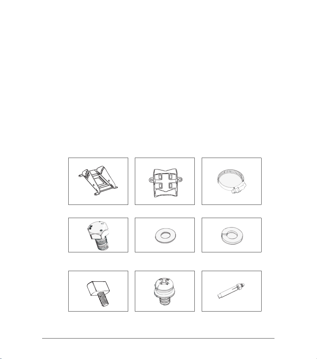
Figure 1. Mounting kit contents
Dynamic bracket Static bracket Steel clamps (2 pieces)
Package Contents
Hex bolt (4 pieces) Flat washer (4 pieces) Split lock washer (4 pieces)
Thumb screws (2 pieces) Machine screw (8 pieces) Wall anchor with metal cone
and hex nut (2 pieces)
3
Unpacking the ZoneFlex Wireless Bridge
Package Contents
Bottom Cover and Accessories
Each bottom cover accessory bag contains:
■ Bottom cover of the Wireless Bridge
■ DC terminal block
■ 20mm x 30mm sealing strips (2 pieces)
■ Sealing plug
■ White P-clip cable clamp (2 pieces)
■ Machine screws (2 pieces)
■ Machine screws with washers (3 pieces)
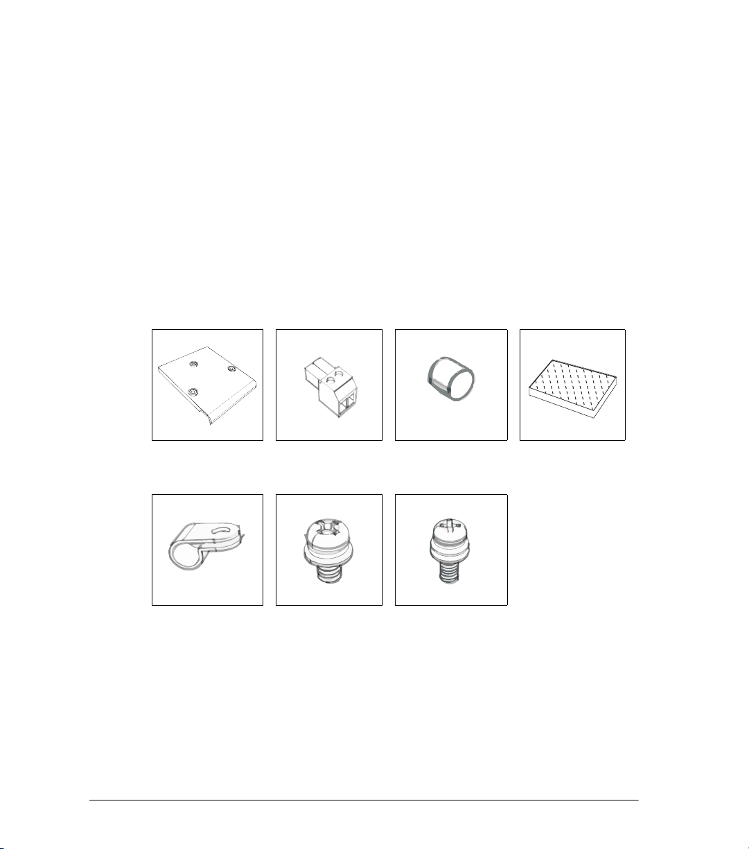
Figure 2. Bottom cover and accessory package contents
Bottom cover DC terminal block Sealing Plug Sealing Strips (2
pieces)
White P-clip cable
clamp
Machine screw (2
pieces)
Machine screw with
washer (3 pieces)
4

Before You Begin
Prepare the Required Hardware and Tools
3 Before You Begin
Prepare the Required Hardware and Tools
You must supply the following tools and equipment:
■ A notebook computer running Windows 2000/XP/Vista and installed with one wireless
802.11b/g network card and one Ethernet card
■ 6mm flathead screwdriver
■ 6mm Phillips screwdriver
■ 10mm ratchet wrench
■ 3mm Phillips screwdriver (if you will be using DC power)
■ Electric drill with 8mm drill bit (if mounting on a flat surface)
NOTE: At the beginning of each procedure, this guide lists the specific tools, accessories,
and equipment that you will need to complete the procedure.
Get to Know the Hardware Features
Figure 3 and Figure 5 identify the Wireless Bridge features that are relevant to the
installation and mounting instructions that this guide provides. Before you begin the
installation process, Ruckus Wireless recommends that you become familiar with these
features.
5
Before You Begin
5
1
2
4
3
Get to Know the Hardware Features
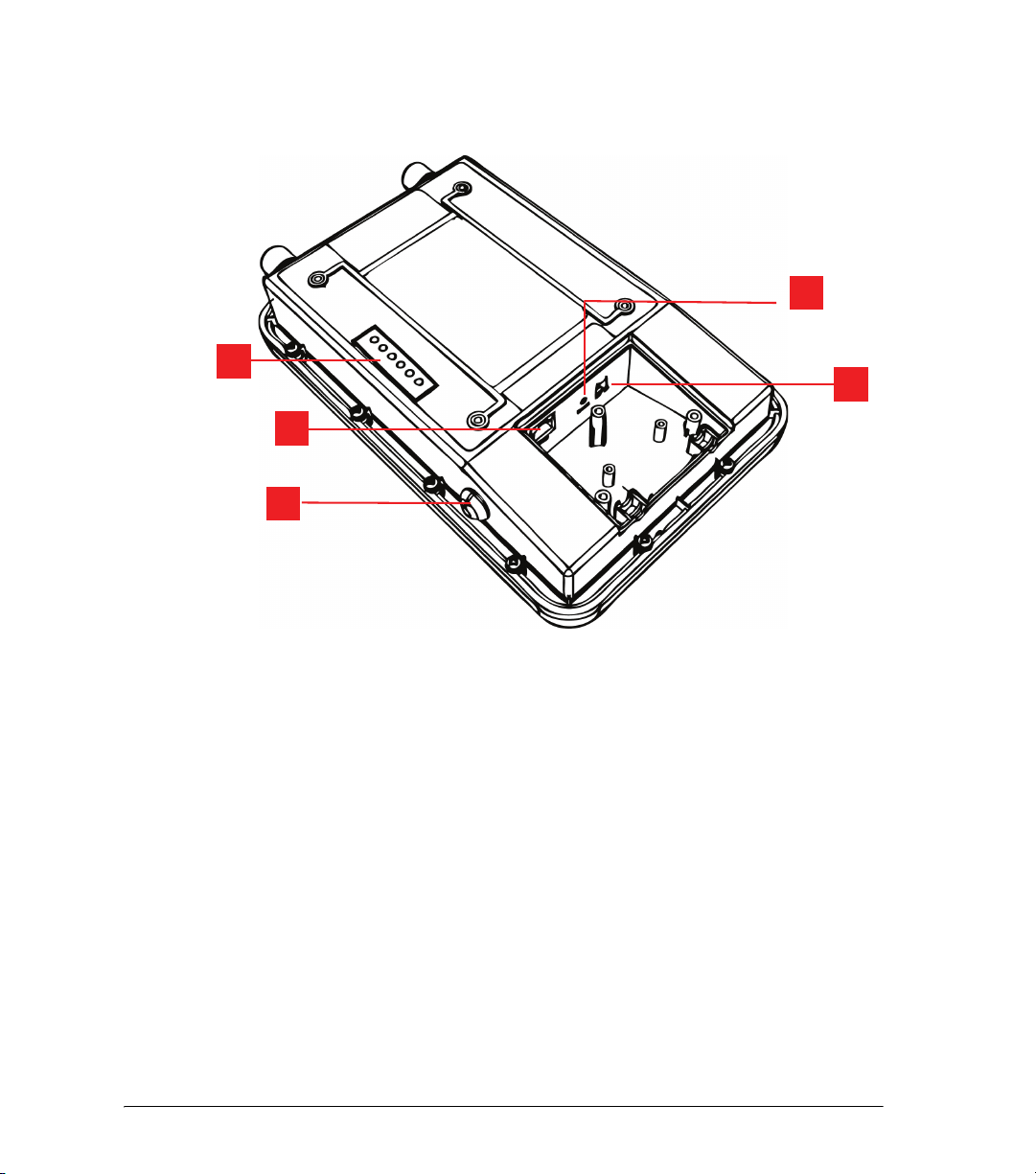
Figure 3. Wireless Bridge LEDs and bottom connectors
6

Before You Begin
Get to Know the Hardware Features
Table 1. LEDs and bottom panel connectors
No Label Description
1 LEDs See “
LED Colors and What They Mean” below for more
information.
2 RJ45 LAN port that supports Power over Ethernet (PoE) and 10/
100/1000 Mbps network connections
3 Reset Using a pointed object (for example, a pen), press this
button to restart the Wireless Bridge or to restore it to
factory default settings:
• To restart the Wireless Bridge, press the Reset button
once.
• To restore the Wireless Bridge to factory default, press
the Reset button for six (6) seconds.
WARNING: Restoring the Wireless Bridge to factory
default settings removes all configuration changes that
you have made. These include the IP address, password,
access control list, and wireless settings. Returning the
configuration of these features to their factory default
settings may result in network connectivity issues.
4 12V DC In addition to PoE, you can also use direct current or DC
(from a battery, for example) to supply power to the
Wireless Bridge.
5 Aiming Button Press this button to set the Wireless Bridge to Aiming
Mode. When Aiming Mode is set, the LEDs can be used
to determine signal strength. See “
Aiming Mode” for
more information.
7

Before You Begin
LED 1
LED 2
LED 3
LED 4
LED 5
LED 6
Get to Know the Hardware Features
LED Colors and What They Mean
The ZoneFlex 7731 Wireless Bridge includes 6 dual color LEDs. The LEDs function in two
modes, normal operation mode and aiming mode.
Figure 4. LED Indicators
■ For Normal Operation Mode LED states and what they indicate, refer to Tab le 2 .
■ For Aiming Mode LED states and what they indicate, refer to Table 3 .
Normal Operation Mode
Table 2. Normal Operation Mode LED indicators
LED Meaning
LED 1 (AIM/PWR) Solid Green = Power on
Off = Power off
LED 2 (LAN) Solid Green = Link Up
Blinking Green = Activity
Off = Link Down
LED 3 (WLAN) Solid Green = Associated
Blinking Green = Not Associated
Off = Radio Off
LED 4 (ROLE) Solid Yellow = This unit is the root bridge
LED 5 & 6 (P0 and P1) Alternating Blinking = Provisioning in process
8
Off = This unit is the non-root bridge
Simultaneous Blinking = Provisioning complete;
reboot pending

Before You Begin
Get to Know the Hardware Features
In Normal Operation Mode, the LED indicators are off when disconnected, flashing green
while connecting and solid green when a connection has been established.
In Aiming Mode, LED 1 indicates that the Wireless Bridge is in Aiming Mode. LED
indicators 2 - 6 are used together to indicate signal strength, and should be read from
bottom to top (the higher the LEDs go, the stronger the signal).
Aiming Mode
Table 3. Aiming Mode LED indicators
LED Meaning
LED 6 Signal strength 5
LED 5 Signal strength 4
LED 4 Signal strength 3
LED 3 Signal strength 2
LED 2 Signal strength 1
LED 1 (AIM/PWR) Solid Yellow = Aiming Mode
Solid Green = Normal Operation Mode
Off = Off
In Aiming Mode, each LED has three states to represent different values. Solid yellow
indicates the highest value, flashing yellow indicates medium value and off indicates the
lowest value. If all six LEDs are solid yellow, the Wireless Bridge has the strongest signal
possible. If some LEDs are flashing yellow or off, reposition the Wireless Bridge to achieve
a better signal.
Push Buttons
The ZoneFlex 7731 includes two push buttons:
■ A recessed factory default reset button
■ A large blue Aiming Mode button that sets the bridge to Aiming Mode
To reset the unit to its factory defaults, press and hold the Reset button for six (6) seconds.
Press and hold the blue Aiming button for four (4) seconds to initiate aiming between the
root and non-root bridge.
CAUTION: Resetting the ZoneFlex 7731 to its factory defaults will result in loss of all
configuration settings, including the pre-provisioning (pairing of the root and non-root
bridge) settings that were enabled prior to shipping. If you do need to reset to defaults,
you will need to re-provision the pair.
9
Before You Begin
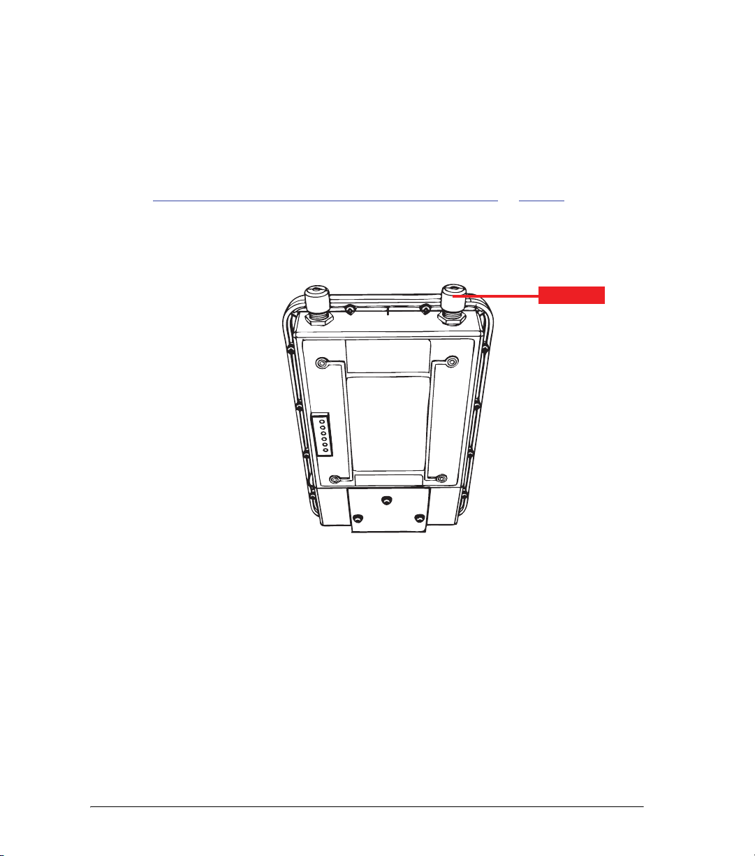
Metal Cap
Get to Know the Hardware Features
External Antennas
The ZoneFlex 7731 Outdoor Wireless Bridge includes one purpose designed internal
directional antenna. If you want to extend the range of your wireless network, you can
connect two external high gain antennas to the standard N-type external antenna
connectors on the top panel of the Wireless Bridge. The antennas must have a gain of less
than 23dBi to comply with FCC and CE regulations. For more information, refer to
Mounting and Connecting the External Antennas (Optional)” on page 44.
“
Figure 5. The antenna connectors are protected by metal caps
10

Preparing the Wireless Bridge Pair for Installation
What You Will Need
4 Preparing the Wireless Bridge Pair for
Installation
This section describes the procedures for setting up the bridge pair before you begin the
physical installation.
ZoneFlex 7731 Outdoor Point to Point Bridges come in pre-provisioned pairs. One is
designated as the “Root Bridge” and one is designated the “Non-Root Bridge.” Therefore, in most situations, you should not need to manually provision the pair. If you do need
to provision (after restoring factory default settings, for example), see the ZoneFlex 7731
User Guide available on the Ruckus Wireless Support Web site for detailed instructions.
The default IP addresses for the root and non-root bridge are as follows:
■ Root Bridge: 192.168.2.1
■ Non-Root Bridge: 192.168.2.254
If you want to assign different IP addresses for either or both units, see “
the IP Address (Optional)” on page 19.
A summary of the steps in this section is below:
1. Connect Ethernet and power to both units.
2. Access the units using an administration computer.
3. Ensure network and wireless settings are correct.
4. Change the IP address (optional).
5. Use the SpeedFlex tool built into the Web interface to test the link between the units.
Step 4: Change
What You Will Need
Before starting with the configuration task, make sure that you have the following requirements ready:
■ An administrative computer (notebook computer) running Microsoft Windows Vista/
XP/2000
■ Mozilla Firefox 2.0 (or later) or Microsoft Internet Explorer 6.0 (or later) installed on the
administrative computer
■ One 5.6mm-6.0mm (outside diameter) Cat5e foil screened twisted pair (FTP) solid
■ cable
■ Two Ethernet cables
■ PoE injector (if not supplied with the Wireless Bridge, you can purchase a third party
802.3af-compliant PoE injector or switch)
■ 6mm Phillips screwdriver
If you are planning to power the Wireless Bridge using a 12v DC connection, you will also
11

Preparing the Wireless Bridge Pair for Installation
Configure the Root Bridge
need the following:
■ One 3.1mm-3.3mm UL1185 (80°, 300V) single shielded DC cable
■ 12v DC, 1A DC power source (for example, a battery)
■ 3mm Phillips screwdriver
Configure the Root Bridge
Step 1: Connect the Power and Ethernet Cables
The procedure for connecting cables to the Wireless Bridge depends on the power source
that you will be using. You can do one of the following:
■ Use Power Over Ethernet
■ Use DC Power
NOTE: You only need to connect one type of power source at this point, even if you are
planning to use both PoE and DC power in your final deployment.
Use Power Over Ethernet
1. Take out the PoE injector and the power adapter from the Wireless Bridge package.
2. Obtain two Ethernet cables.
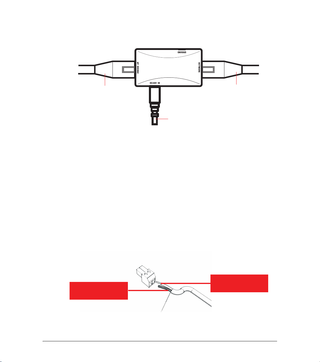
3. Connect one end of one Ethernet cable to the AP/BRIDGE port on the PoE injector,
and then connect the other end to the RJ45 port on the ZoneFlex 7731.
4. Connect one end of the other Ethernet cable to the NETWORK port on the PoE
injector.
5. Connect the power jack to the DC 48V IN connector on the PoE injector, and then
plug the power adapter into a power source. The single LED on the PoE injector turns
green.
6. Check the power LED on the ZoneFlex 7731 to ensure power is being supplied to the
bridge.
12
Preparing the Wireless Bridge Pair for Installation
To Ad m i n
Computer
To Bridge
To AC P o w e r Sou rc e
Ground Wire to
V- Terminal
12V DC Wire to
V+ Terminal
Configure the Root Bridge
Figure 6. Connect the Ethernet cables and power adapter to the PoE injector
You have completed connecting the Wireless Bridge to a PoE power source.
Use DC Power
To use DC to power the Wireless Bridge, you need to connect a DC cable (not supplied
with the Wireless Bridge) to the DC terminal block.
1. Take out the DC terminal block from the small plastic bag that contains the bottom
cover of the Wireless Bridge.
2. Connect the DC cable’s ground wire to V- terminal. If you are looking at the terminal
block with the wiring terminal screws on top, the V- terminal is on the left side.
3. Connect the DC cable’s +12v DC wire to the V+ terminal. If you are looking at the
terminal block with the wiring terminal screws on top, the V+ terminal is on the right
side.
Figure 7. Connect the ground wire to the V- terminal and the +12v DC wire to the V+
terminal
13
 Loading...