

Senao Networks ENH200 User Manual

Wireless Outdoor AP/CB
User Manual
Version : 1.0
Table of Contents

1 PRODUCT OVERVIEW ........................................................................................................................................................... 5
1.1 F
EATURE
......................................................................................................................................................................... 5
1.2 B
ENEFITS
........................................................................................................................................................................ 7
1.3 P
ACKAGE CONTENTS
1.3 S
YSTEM REQUIREMENT
.........................................................................................................................................................8
..................................................................................................................................................... 8
2 ENH200 MULTI-FUNCTION INSTRUCTION GUIDE ................................................................................................................9
2.1 A
CCESS POINT
2.2 A
CCESS POINT WITH
2.3 C
LIENT BRIDGE
2.4 WDS B
2.7 C
LIENT ROUTER
3 COMPUTER CONFIGURATION INSTRUCTION.....................................................................................................................12
3.1 A
SSIGN A STATIC
3.2 L
OGGING METHOD
4 STATUS ................................................................................................................................................................................ 14
4.1 S
AVE/LOAD
4.2 M
AIN
4.3 W
IRELESS CLIENT LIST
4.4 S
YSTEM LOG
4.5 C
ONNECTION STATUS
................................................................................................................................................................. 9
WDS F
UNCTION
.............................................................................................................................................................. 10
RIDGE
................................................................................................................................................................ 10
............................................................................................................................................................. 11
IP......................................................................................................................................................... 12
.........................................................................................................................................................13
................................................................................................................................................................... 14
.......................................................................................................................................................................... 15
..................................................................................................................................................... 16
................................................................................................................................................................. 17
...................................................................................................................................................... 18
.................................................................................................................................. 9
4.6 DHCP C
5 SYSTEM ............................................................................................................................................................................... 20
5.1 S
6 WIRELESS CONFIGURATION ............................................................................................................................................... 22
6.1 W
6.2 W
LIENT TABLE
WITCHING OPERATION MODE
IRELESS SETTINGS
6.1.1 Access Point Mode .......................................................................................................................................... 22
6.1.2 Client Bridge Mode ......................................................................................................................................... 25
6.1.3 WDS Bridge Mode........................................................................................................................................... 27
6.1.4 Client Router Mode ......................................................................................................................................... 29
IRELESS SECURITY SETTINGS
6.2.1 WEP................................................................................................................................................................. 31
6.2.2 WPA-PSK ......................................................................................................................................................... 32
6.2.3 WPA2-PSK .......................................................................................................................................................33
6.2.4 WPA-PSK Mixed...............................................................................................................................................34
6.2.5 WPA ................................................................................................................................................................ 35
...................................................................................................................................................... 19
......................................................................................................................................... 20
....................................................................................................................................................... 22
.......................................................................................................................................... 31
6.2.6 WPA2 .............................................................................................................................................................. 36
6.2.7 WPA Mixed...................................................................................................................................................... 37

6.4 W
IRELESS ADVANCED SETTINGS
6.5 W
IRELESS
MAC F
........................................................................................................................................ 38
ILTER
................................................................................................................................................... 40
6.6 WDS L
7 LAN SETUP .......................................................................................................................................................................... 42
7.1 IP S
7.2 S
8 ROUTER SETTINGS .............................................................................................................................................................. 44
8.1 WAN S
8.2 LAN S
8.3 VPN P
8.4 P
8.5 DMZ........................................................................................................................................................................... 55
9 MANAGEMENT SETTINGS ..................................................................................................................................................56
INK SETTINGS
ETTINGS
.................................................................................................................................................................. 42
PANNING TREE SETTINGS
ETTINGS
8.1.1 Static IP ........................................................................................................................................................... 44
8.1.2 DHCP (Dynamic IP) .......................................................................................................................................... 46
8.1.3 PPPoE (Point-to-Point Protocol over Ethernet)................................................................................................ 48
8.1.4 PPTP (Point-to-Point Tunneling Protocol)........................................................................................................ 50
ETTINGS (ROUTER MODE
ASS THROUGH
ORT FORWARDING
...................................................................................................................................................... 41
............................................................................................................................................... 43
............................................................................................................................................................. 44
) ...................................................................................................................................... 52
...................................................................................................................................................... 53
........................................................................................................................................................ 54
9.1 A
DMINISTRATION
9.2 M
ANAGEMENT
9.3 SNMP S
9.4 B
ACKUP/RESTORE SETTINGS
9.5 F
IRMWARE UPGRADE
9.6 T
IME SETTINGS
9.7 LOG............................................................................................................................................................................. 63
9.8 D
IAGNOSTICS
10 NETWORK CONFIGURATION EXAMPLE............................................................................................................................ 65
10.1 A
CCESS POINT
10.2 C
LIENT BRIDGE MODE
10.3 WDS B
10.4 C
LIENT ROUTER
E
UROPE – EU DECLARATION OF CONFORMITY
...........................................................................................................................................................56
VLAN .................................................................................................................................................... 58
ETTINGS
...........................................................................................................................................................59
............................................................................................................................................. 60
...................................................................................................................................................... 61
.............................................................................................................................................................. 62
................................................................................................................................................................ 64
............................................................................................................................................................. 65
.................................................................................................................................................. 66
RIDGE MODE
.................................................................................................................................................... 67
...........................................................................................................................................................68
........................................................................................................................... 71

About This Document
This document is written by EnGenius Inc. EnGenius Inc. has rights to change any of this document
without notice and all rights reserved. This document can only be used for guiding the configuration
setup of EnGenius products.
This document is to demonstrate the EnGenius ENH200 Wireless Access Point & Client Bridge.
Please read the document carefully before setup the ENH200. If the damage is caused by the
inappropriate behaviors, the repair will not be included in the warranty.
Formats
This document uses following symbols to indicate and highlight special message.
Caution: This symbol represents the Vital message and it could be harmful for the
device or settings.
Note: This symbol represents the important message for the settings.
Tip: This symbol represents the alternative choice that can save time or resources.
Before you start
The following equipments are essential to setup the ENH200:
1. One Computer/Notebook and internet accessible.
2. Two Ethernet Cables.
3. One EnGenius device – ENH200.
The equipments listed above are only for setup the ENH200, you will need more
equipment to connect the internet and it is depend on your internet network structure. You may
refer to the chapter 2 for more information.
__________________________________________________

1 Product Overview
Thank you for using ENH200. It is a powerful, enhanced, enterprise scale product with 4+1
multi-functions Access Point, Access Point with WDS function, Client Bridge, WDS Bridge, and Client
Router.
ENH200 uses the latest wireless technology 802.11n standard. It has faster transmit/receive wireless
speed. ENH200 gives you a great advantage to save your time and cost to expend your network. It is
also compatible with 802.11b and 802.11g.
ENH200 is easily to install almost anywhere with Power over Ethernet for quick indoor installation
and regular Power by Adapter. ENH200 can manage power level control, Narrow bandwidth selection,
Traffic shaping and Real-time RSSI indicator. ENH200 is fully support of security encryption including
Wi-Fi Protected Access (WPA-PSK/WPA2-PSK), 64/128/152-bit WEP Encryption and IEEE 802.1x with
RADIUS Accounting.
1.1 Feature
The following list describes the design of the ENH200 made possible through the power and
flexibility of wireless LANs:
a) Difficult-to-wire environments
There are many situations where wires cannot be laid easily. Historic buildings, older
buildings, open areas and across busy streets make the installation of LANs either
impossible or very expensive.
b) Temporary workgroups
Consider situations in parks, athletic arenas, exhibition centers, disaster-recovery,
temporary offices and construction sites where one wants a temporary WLAN established
and removed.
c) The ability to access real-time information
Doctors/nurses, point-of-sale employees, and warehouse workers can access real-time
information while dealing with patients, serving customers and processing information.
Frequently changed environments
d)
Show rooms, meeting rooms, retail stores, and manufacturing sites where frequently
rearrange the workplace.

e) Wireless extensions to Ethernet networks
Network managers in dynamic environments can minimize the overhead caused by moves,
extensions to networks, and other changes with wireless LANs.
f) Wired LAN backup
Network managers implement wireless LANs to provide backup for mission-critical
applications running on wired networks.
g) Training/Educational facilities
Training sites at corporations and students at universities use wireless connectivity to ease
access to information, information exchanges, and learning.
Benefits
High Speed Data Rate Up
to 150Mbps
High Output Power up to
26 dBm
IEEE 802.11b/g/n
Compliant
4+1 Multi-Function Users can use different mode in various environment
Point-to-point,
Point-to-multipoint
Wireless Connectivity
Channel Bandwidth
Selection
Support RSSI Indicator
(CB mode)
Power-over-Ethernet
Support Multi-SSID
function (4 SSID) in AP
mode
WPA2/WPA/ WEP/ IEEE
802.1x support
MAC address filtering in
AP mode
PPPoE/PPTP function
support (AP Router/CR
mode)
SNMP Remote
Configuration
Management
Capable of handling heavy data payloads such as MPEG video
streaming
Extended excellent Range and Coverage
Fully Interoperable with IEEE 802.11b/IEEE 802.11g/IEEE 802.11n
compliant devices
Let users transfer data between two buildings or multiple buildings
Using different bandwidth to reach varied distance
Users can select the best signal to connect with AP easily
Flexible Access Point locations and cost savings. ENH200 must uses
the adapter provided in the package.
Allow clients to access different networks through a single access
point and assign different policies and functions for each SSID by
manager
Fully support all types of security types.
Ensures secure network connection
Easy to access internet via ISP service authentication
Help administrators to remotely configure or manage the Access
Point easily.
QoS (WMM) support Enhance user performance and density

1.2 Benefits
Access Point Mode Use this feature to setup the access point’s configuration information.
It has support adjusting transmit power and channel. Client can access
the network with different regulatory settings and automatically
change to the local regulations.
Client Bridge Mode Use this feature to connect to an Access Point and enjoy the great
speed of surfing internet.
WDS Mode Use this feature to link multiple APs in a network, All clients associated
with any APs can communicate each other like an ad-hoc mode.
Client Router Mode This feature functions completely opposite but similarly with AP
Router Mode. Client Router connected to an AP wirelessly and
transmit internet connection protocol through AP to access the
internet.
Multiple SSIDs ENH200 supports up to 4 SSIDs on your access point. The following
options can be set to each SS to each SSID:
- SSID for public or private network
- Authentication is fully supported
- VLAN identifier
- Radius accounting identifier
- Profile isolation for infrastructure network
VLAN Specify a VLAN number for each SSID to separate the services among
clients.
QoS Use this feature to limit the incoming or outgoing throughput.
Wi-Fi Protect Access Wi-Fi Protect Access is a standard-based interoperable security
enhancement that increases the level of data protection and access
control for existing and future wireless LAN system. It is compatible
with IEEE 802.11i standard WPA leverages TKIP and 802.1X for
authenticated key management.

1.3 Package Contents
Open the package carefully, and make sure that none of the items listed below are missing. Do not
discard the packing materials, in case of return; the unit must be shipped in its original package.
1* Wireless Access Point / Client Bridge (ENH200)
1* 24V/0.6A Power Adapter
1* QIG
1* CD (User Manual)
Using other Power Adapter than the one included with ENH200 may cause damage of the device.
1.3 System Requirement
The following conditions are the minimum system requirement.
A computer with an Ethernet interface and operating under Windows XP, Vista, 7 or Linux.
Internet Browser that supports HTTP and JavaScript.
2 ENH200 Multi-Function Instruction Guide
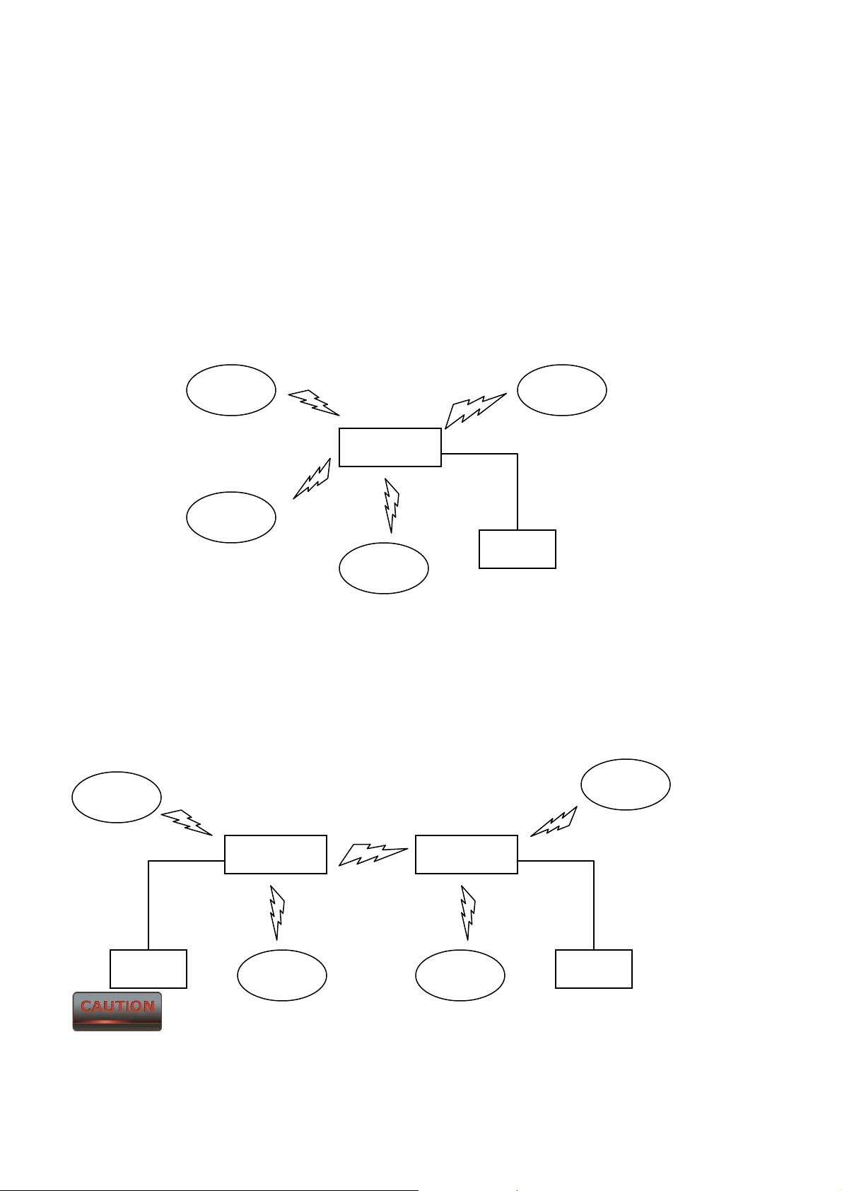
2.1 Access Point
In the Access Point Mode, ENH200 function likes a central connection for any stations or clients that
support IEEE 802.11b/g/n network. Stations and Client must configure the same SSID and Security
Password to associate within the range. ENH200 supports 4 different SSIDs to separate different
clients at the same time.
Client
Client
SSID3
SSID2
SSID4
ENH200
Client
SSID1
Ethernet
Client
Client
2.2 Access Point with WDS Function
ENH200 also supports WDS function in Access Point Mode without losing AP’s capabilities. Configure
others Access Point’s Wireless MAC Address in both Access Point devices to enlarge the wireless area
by enabling WDS Link Settings. WDS function can support up to 8 different AP’s MAC addresses.
Client
WDS
Client
recommended using ENH200 if you would like to use this service.
Client Client
Not every Access Point device has support WDS in Access Point Mode. It is
ENH200
Client
ENH200
Client
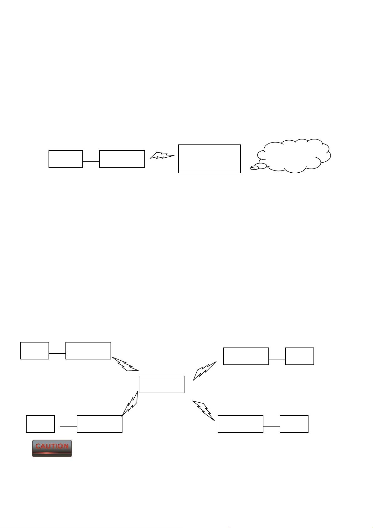
2.3 Client Bridge
In the Client Bridge Mode, the ENH200 function likes a wireless client connecting to an Access Point
wirelessly and surf internet whenever you want. Using Site Survey to scan all the Access Point within
the range and configure its SSID and Security Password to associate with it. Connect you station to
the LAN port of the ENH200 via Ethernet.
Client
ENH200
Access Point /
Wireless Router
Internet
2.4 WDS Bridge
In the WDS Bridge Mode, the ENH200 can wirelessly connect different LANs by just simply configure
each other’s MAC Address and Security Settings. This mode is used when two wired LANs locate in
small distance and want to communicate each other. The best solution is using ENH200 wirelessly
connect two wired LANs. WDS Bridge Mode can establish 16 WDS links, the network diagram is like a
Star.
Client
Client
frequency channel, more APs connected together may lower throughput. Please be aware to avoid
loop connection diagram, otherwise enable Spanning Tree Function.
ENH200
ENH200
WDS Bridge Mode is unlike Access Point. APs linked by WDS are using the same
WDS
WDS
ENH200
WDS
WDS
ENH200
ENH200
Client
Client
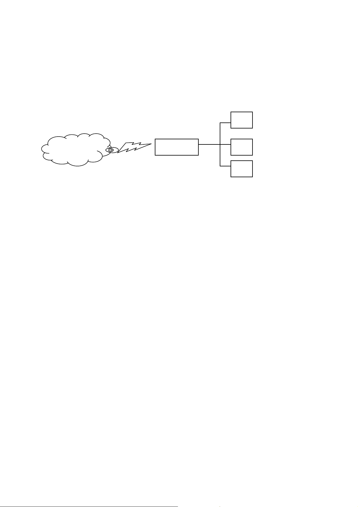
2.7 Client Router
In the Client Router Mode, the ENH200 has DHCP Server build inside that allows many LANs
automatically generate an IP address to share the same Internet. Connect an AP/WISP Wirelessly and
connect to LANs via wired. Client Router Mode is act completely opposite to the AP Router Mode.
PC
AP / WISP
ENH200
PC
PC
3 Computer Configuration Instruction
The default operating mode is Client Bridge. Client Bridge will not assign an IP address to the
computer/notebook. Therefore, follow the steps to assign an IP address to your Ethernet card.
3.1 Assign a Static IP
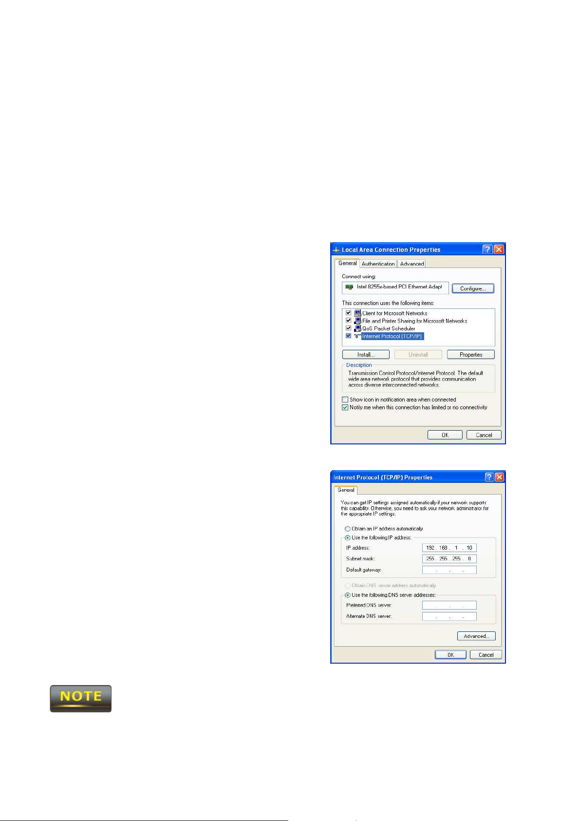
In order to configure ENH200, please follow the instruction below:
1. In the Control Panel, double click Network
Connections and then double click on the connection of
your Network Interface Card (NIC). You will then see the
following screen.
2. Select Internet Protocol (TCP/IP) and then click on the
Properties button. This will allow you to configure the
TCP/IP settings of your PC/Notebook
3. Select Use the following IP address radio button and
then enter the IP address and subnet mask. Ensure that
the IP address and subnet mask are on the same subnet
as the device.
4. Click on the OK button to close this window, and then
close LAN properties window.
IP Address entered in the TCP/IP Properties needs to be at the same subnet of the ENH200 IP Address.
For example: ENH200’s default IP Address is 192.168.1.1 so the IP Address in the TCP/IP settings
could be 192.168.1.10.
3.2 Logging Method
After complete the IP settings from last section, you can now access the web-based configuration
menu.
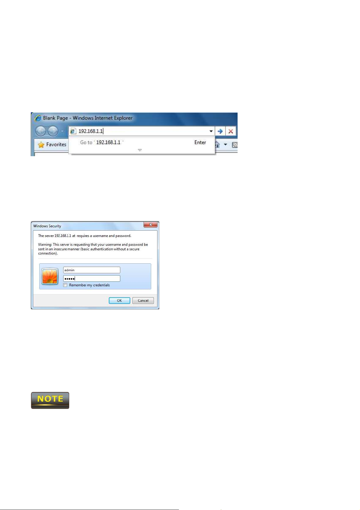
1. Open web browser
2. Enter IP 192.168.1.1 into you address filter.
Caution: If you have changed the ENH200 LAN IP address, make sure you enter the correct IP
Address.
3. After connected to the ENH200 successfully, browser will pop out a Windows Security window.
Please enter the correct Username and Password.
4. The default Username and Password are both admin.
If you have changed the Username and Password, please enter your own Username and
Password.
4 Status
Status section is on the navigation drop-down menu. You will then see three options: Main, Wireless
Client List, System Log, WDS Link Status, Connection Status, and DHCP Client Table. Each option is
described in detail below.
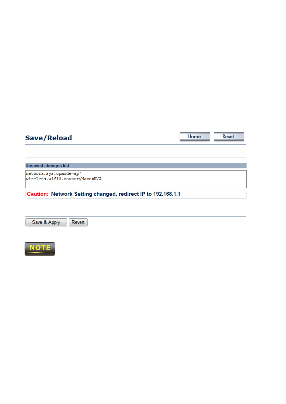
4.1 Save/Load
This page allows viewing the modified changes. The changes show in the Unsaved changes list table.
You can decide to cancel all the changes or to compile to the new setting.
You cannot cancel the specific settings. You can only compile all the settings or revert to the previous
settings.
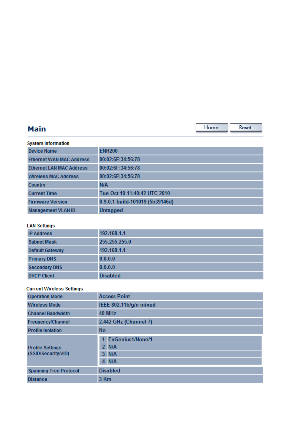
4.2 Main
Click on the Main link under the Status drop-down menu or click Home from the top-right of the
webpage. The status that is displayed corresponds with the operating mode that is selected.
Information such as operating mode, system up time, firmware version, serial number, kernel
version and application version are displayed in the ‘System’ section. LAN IP address, subnet mask,
and MAC address are displayed in the ‘LAN’ section. In the ‘Wireless section, the frequency, channel
is displayed. Since this device supports multiple-SSIDs, the details of each SSID, such as ESSID and its
security settings are displayed.
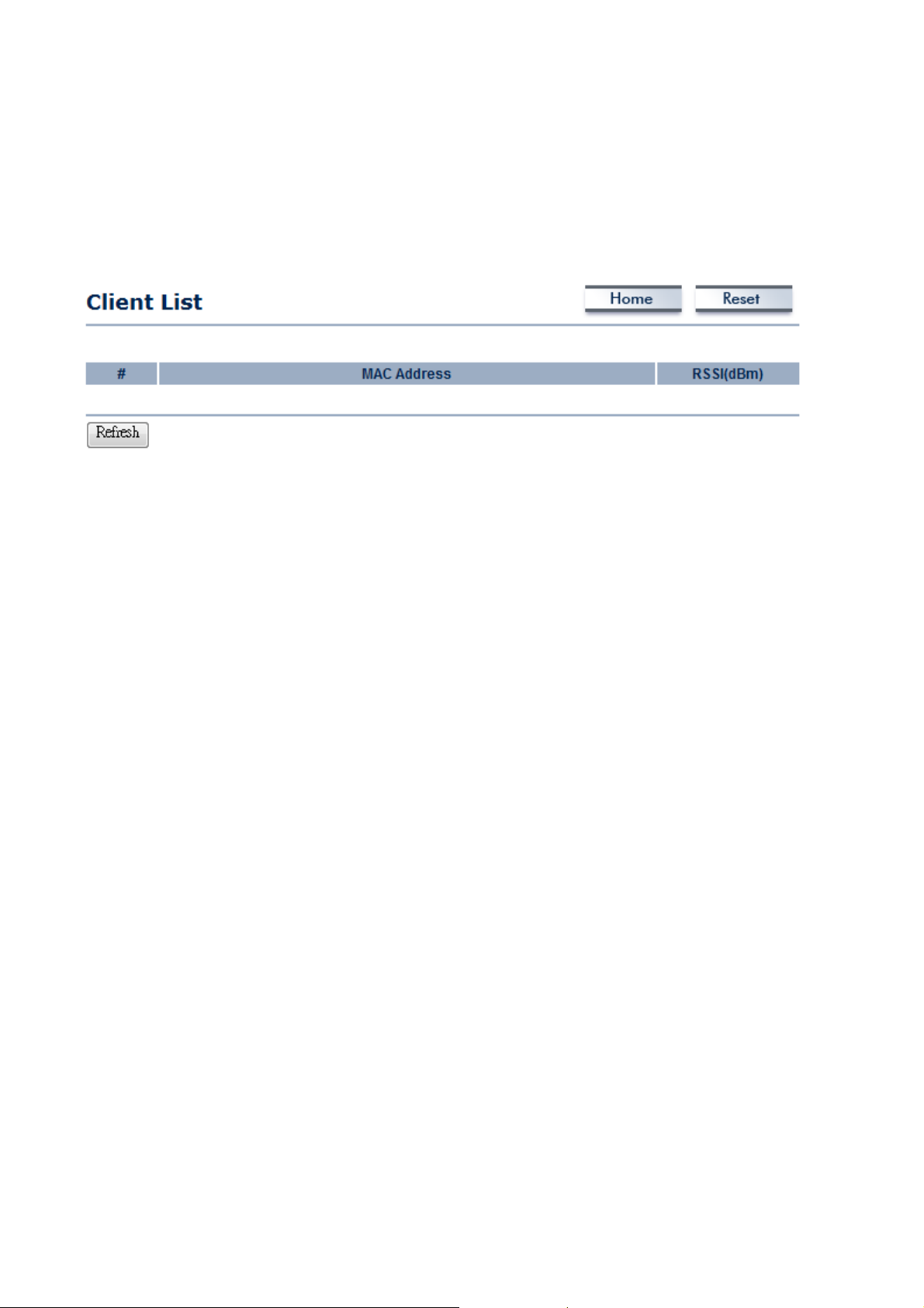
4.3 Wireless Client List
Click on the Wireless Client List link under the Status drop-down menu. This page displays the list of
Clients that are associated to the ENH200.
The MAC addresses and signal strength for each client is displayed. Click on the Refresh button to
refresh the client list
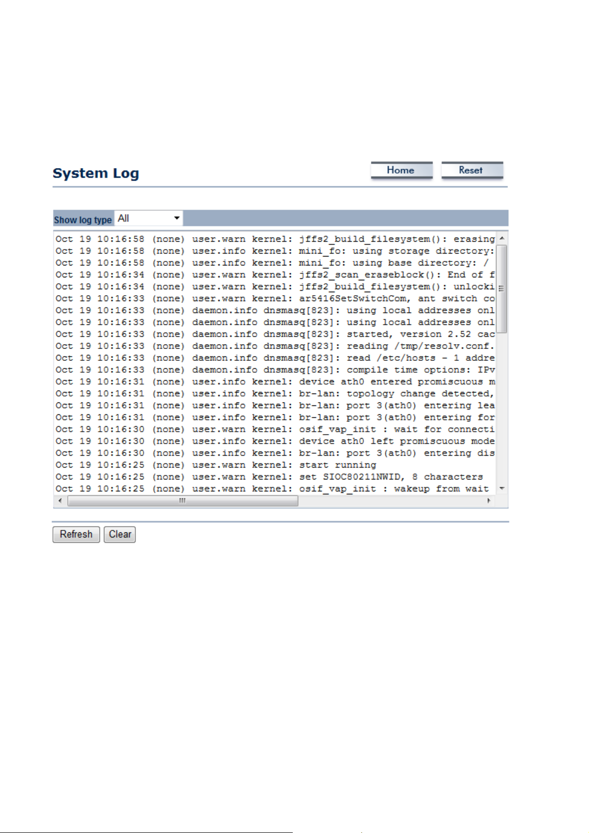
4.4 System Log
Click on the System Log link under the Status drop-down menu. The device automatically logs
(records) events of possible interest in its internal memory. If there is not enough internal memory
for all events, logs of older events are deleted, but logs of the latest events are retained.
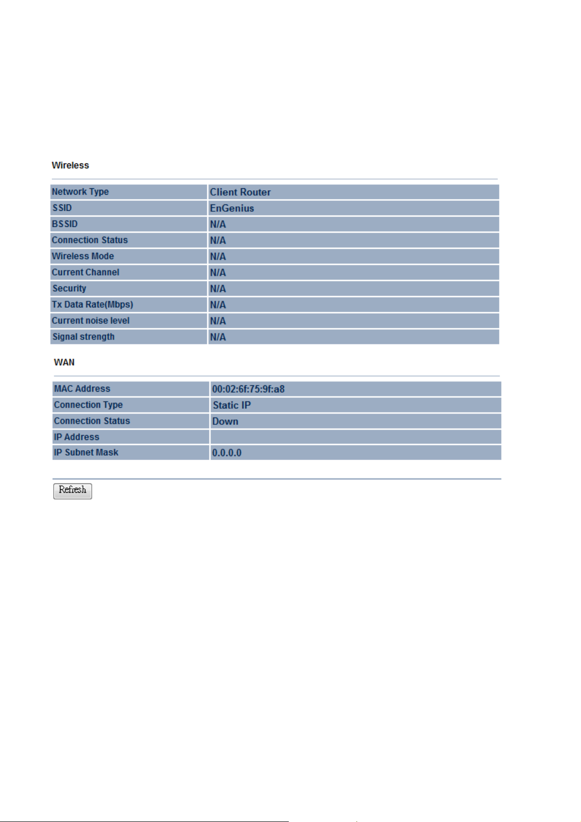
4.5 Connection Status
Click on the Connection Status link under the Status drop-down menu. This page displays the
current status of the network, including network type, SSID, BSSID, connection status, wireless
mode, current channel, security, data rate, noise level and signal strength.
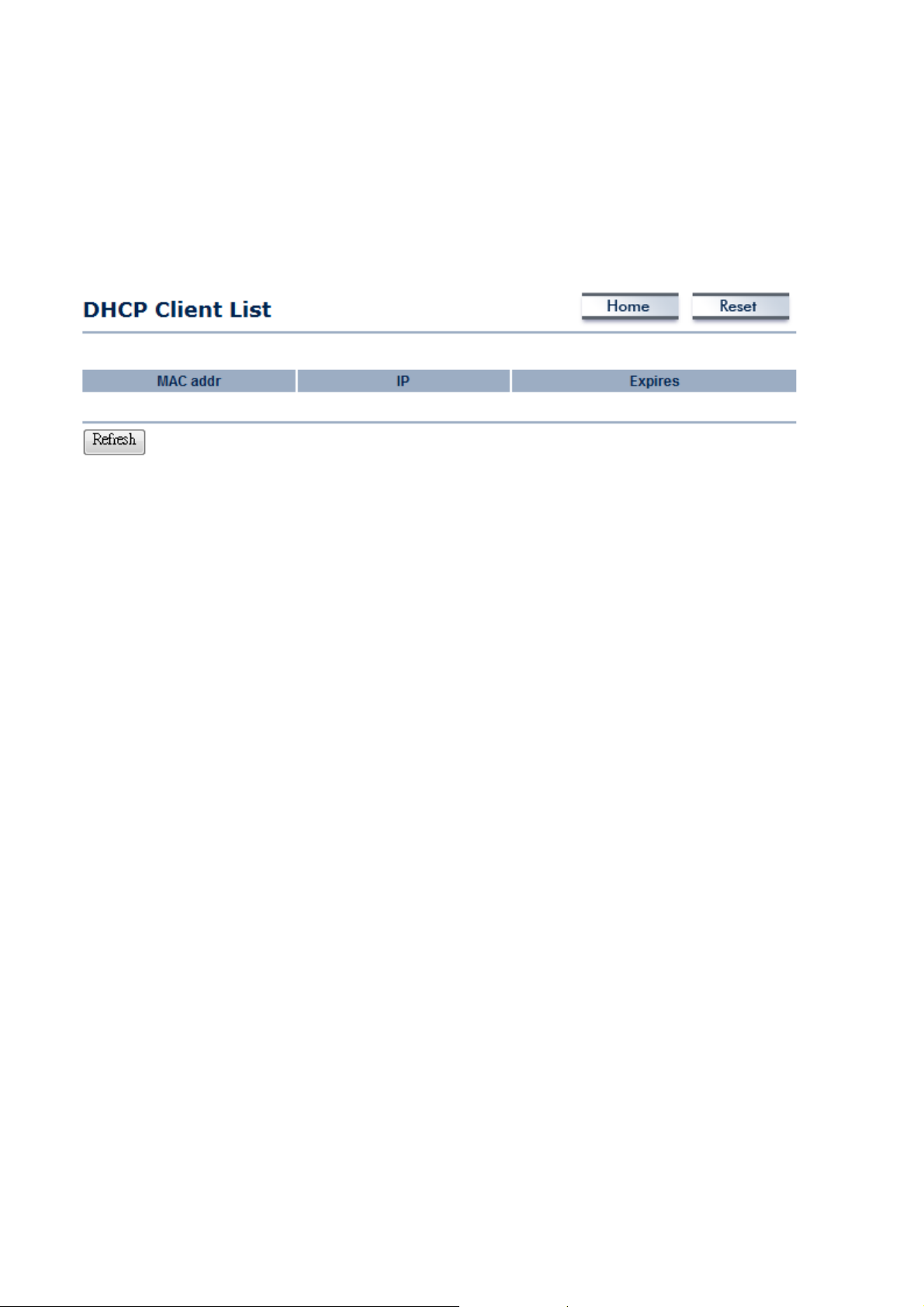
4.6 DHCP Client Table
Click on the DHCP Client List link under the Status drop-down menu. This page displays the list of
Clients that are associated to the ENH200 through DHCP.
The MAC addresses and signal strength for each client is displayed. Click on the Refresh button to
refresh the client list.
5 System
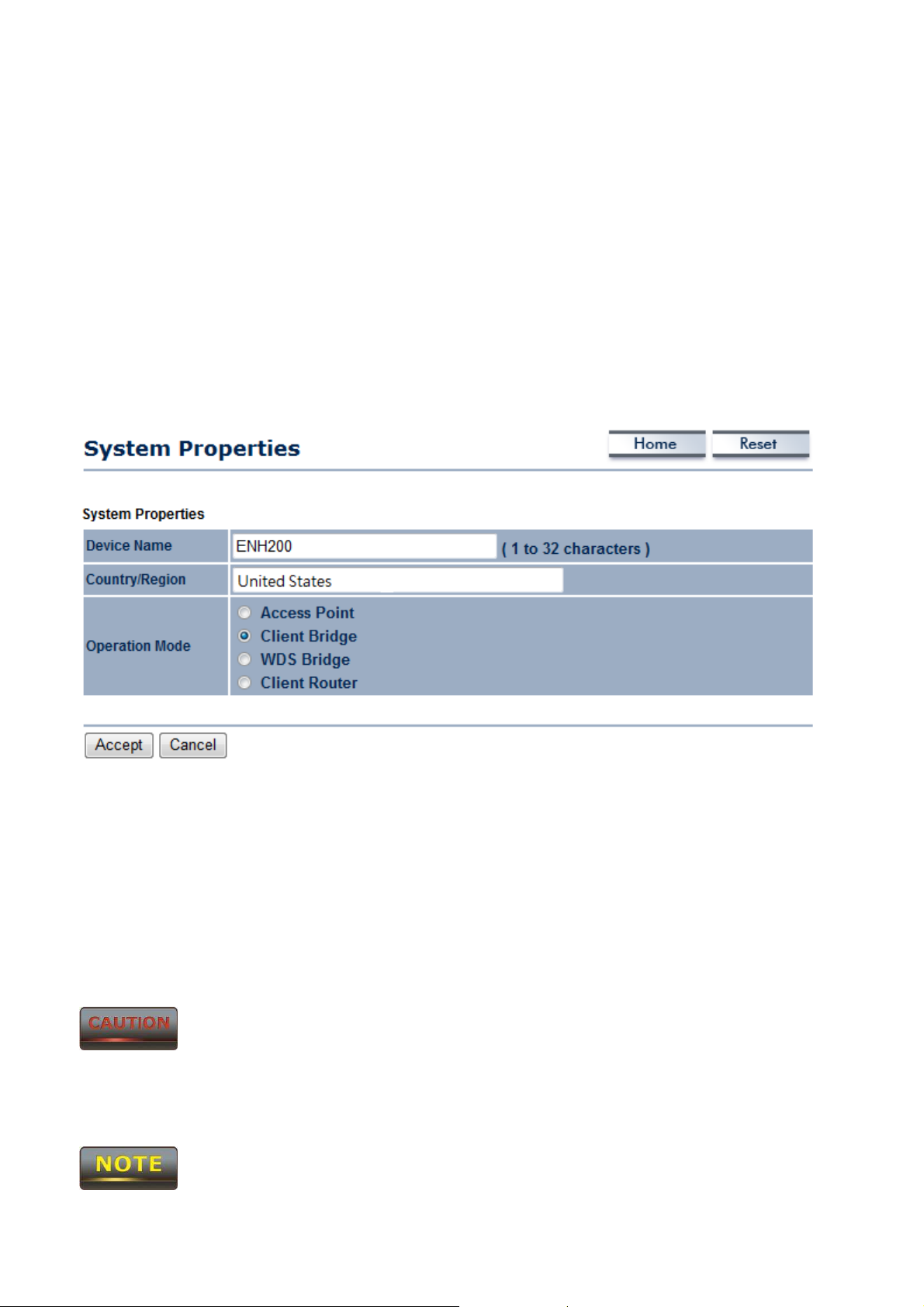
5.1 Switching Operation Mode
The ENH200 supports 4+1 operation modes: Access Point, Client Bridge, WDS Bridge, and Client
Router. In order to switching between the operating modes, please go to System -> Operation mode.
Click System Properties under System Section to begin.
.
Device Name: Specify a name for the device. It is not the broadcast SSID. It will be shown in SNMP
management.
Country/Region: United States
Operation Mode: Select an operation mode via Radio Button.
Click Accept to confirm the changes.
Accept does not compile the changes, you must go to Status -> Save/Load to apply the new settings.
Please refer to the chapter 4.1 for more detail.
If you would like to use Access Point with WDS Function mode, please select Access Point Mode and

then enable WDS function in the Wireless Network section.
6 Wireless Configuration
This section will guide you through all the wireless settings. Please read the instruction carefully.
Inappropriate setting could lower the performance or affect the network structure. Before you
continue, please make sure you have chosen the correct operating mode.
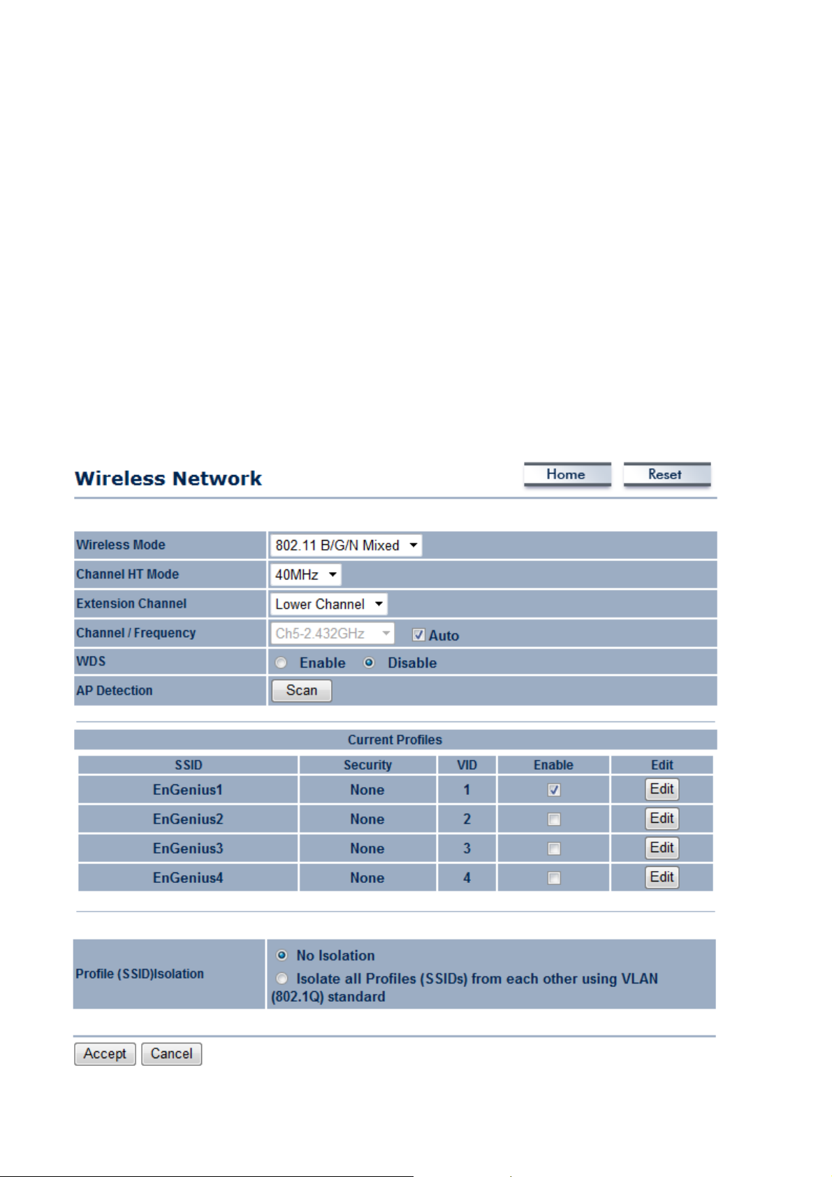
6.1 Wireless Settings
This section is the basic wireless settings. Please read the description carefully and check the steps on
chapter 10 in case you need more detail information.
6.1.1 Access Point Mode
 Loading...