

Page 1
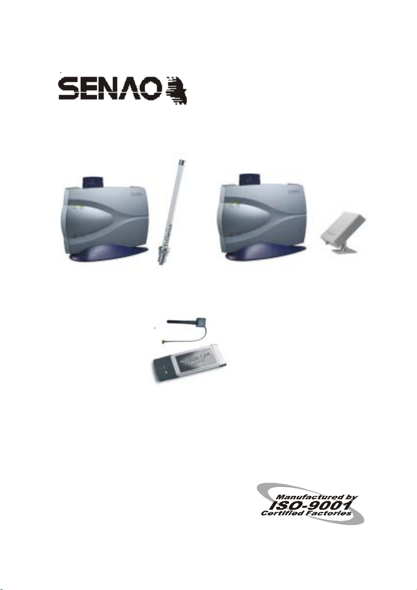
SL-2011CD-GP SL-2011CD-FP
SL-2011CD-DP
Antenna User Guide
Before operating the unit, please read this manual thoroughly,
and retain it for future reference.
1
Page 2
Installing the Antenna
1. Introduction
The Senao access point is designed to perform in a variety of
environments. Implementing the antenna system can greatly improve
coverage and performance. A good communication can only be
achieved with the right antenna. The antenna kits com prise numerous
components, including the antenna, connectors, mounting hardware,
antenna cabling, and in certain product boxes.
2. Type of Antennas
The Senao access point may be bundled with several different
styles of antennas f or use in the 2.4GHz ra nge. Each type of antenna
will offer different coverage capabilities. As the gain of an antenna
increases, there is some tradeoff to its coverage area. Us ually high gain
antennas offer longer cover age d istances, but onl y in a certain direc tion.
The radiation patterns bel ow show the coverage area s of the styles of
omni-directional and uni-directional antennas.
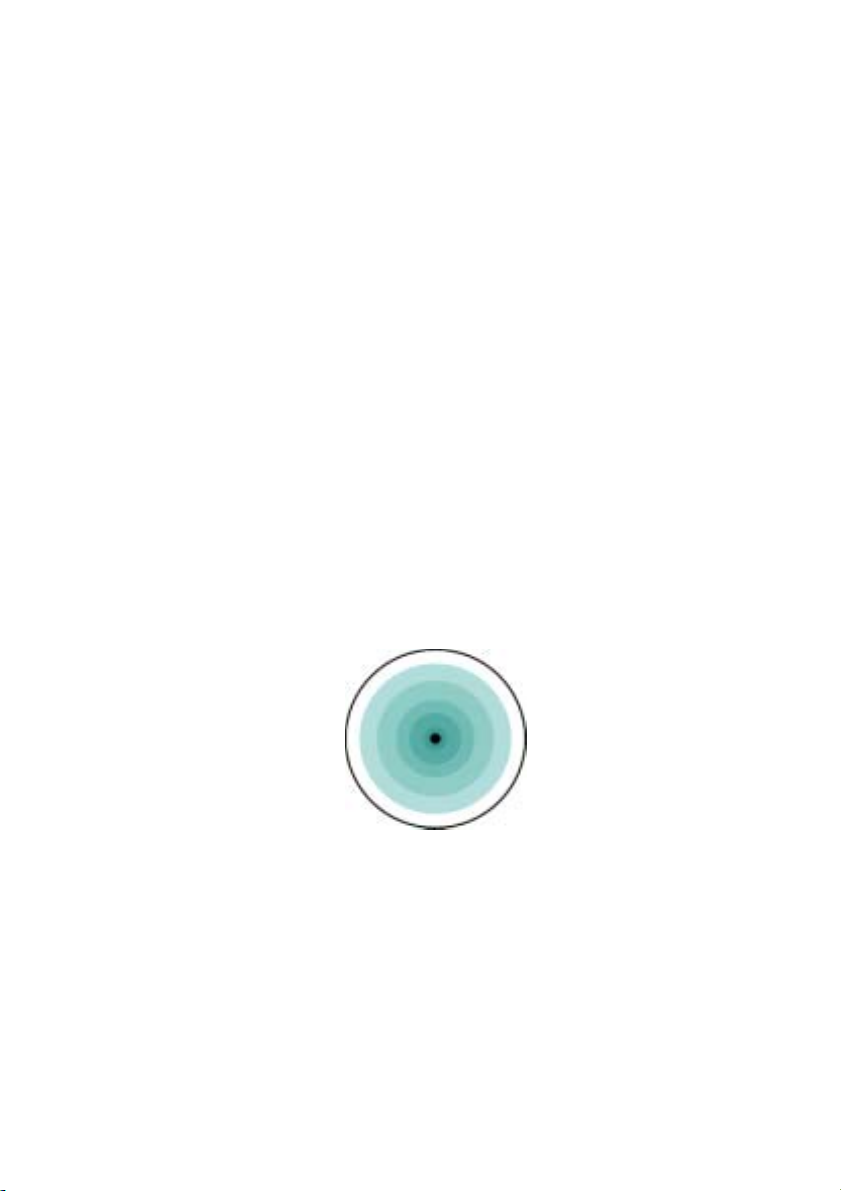
◆Omni-Directional Antennas
An omni-directio na l a nte nn a is designed to pr ov id e a 360- de gree
radiation pattern. This type of antenna is used when coverag e in all
directions from the antenna is required.
Figure 1-1: Omni-Directional Antenna (top-view)
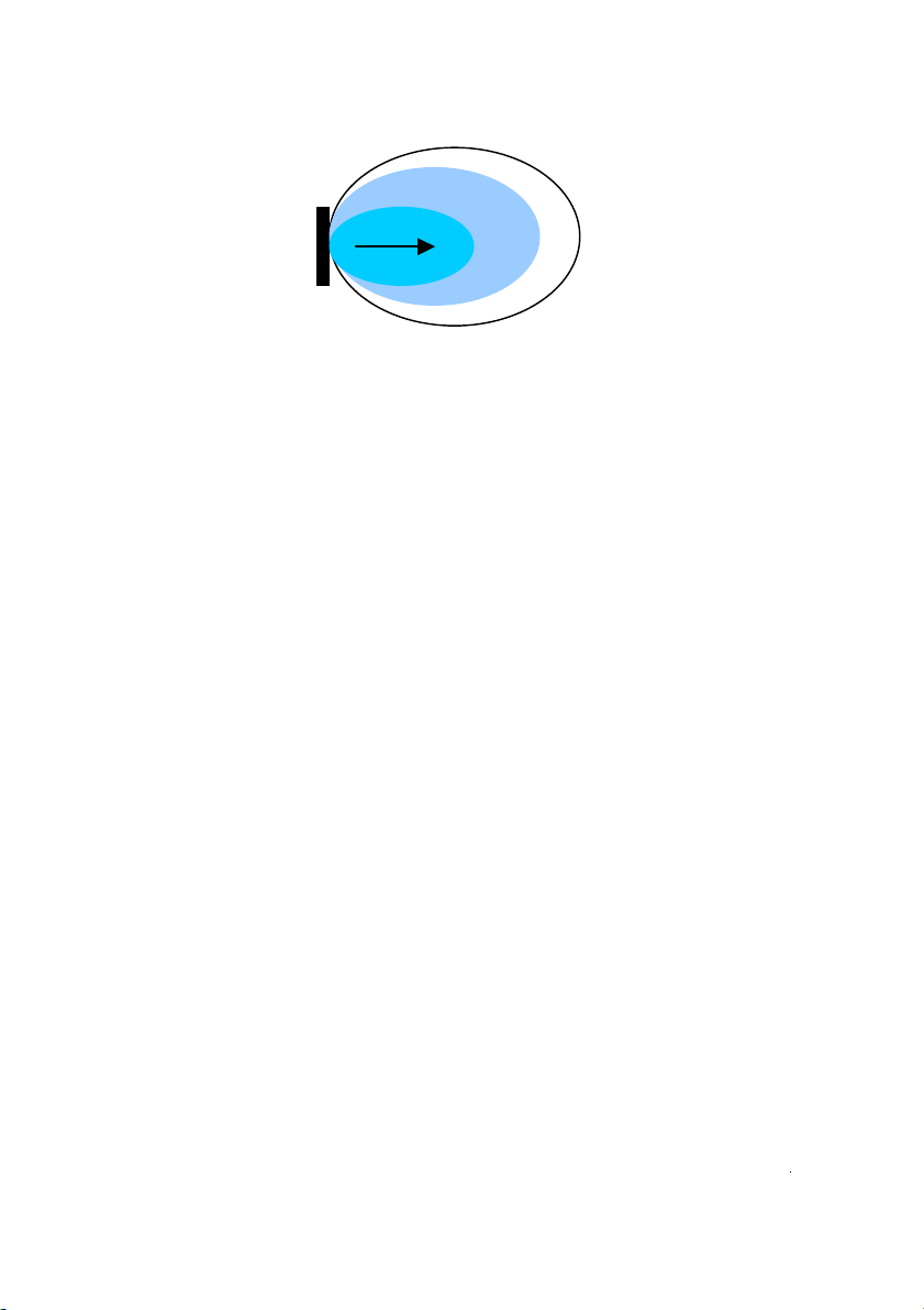
◆Directional Flat Panel Antennas
Directional antenn as have many different st yles and shapes. By
redirecting this energ y, it has the effect of providing more energy in
one direction, and less ene rgy in all other dir ections. As the gain of a
directional antenna increases, the angle of radiation usually
decreases, providing a gr eater coverage distanc e, but with a r educed
coverage angle.
2
Page 3
IMPORTANT NOTE:
FCC RF Radiation Exposure Statement:
This equipment complies with FCC RF radiation exposure limits set forth
for an uncontrolled environment. This equipment should be installed and
operated with a minimum distance of 20 centimeters between the
radiator and your body.
This transmitter must not be co-located or operating in conjunction with
any other antenna or transmitter.
Figure 1-2: Directional Flat Panel Antenna (side view)
3. Antenna placement
The advices below are basic concepts to install an antenna.
The distance between the ante nna and transce iver should be
kept to a minimum to reduce signal loss.
To operate at optimum efficiency, antenna cable should be
kept as short as possible.
3
Page 4
4
4. Installing the 3dBi omni-directional antenna
4-1. Hardware Description
The 3dBi omni-directional antenna is a broadband antenna for the
2.4GHz frequency band featuring an omni-directional pattern with a
normal gain of 3dBi. Before you start installing the antenna, verify the
following items in the antenna kits or in the product package.
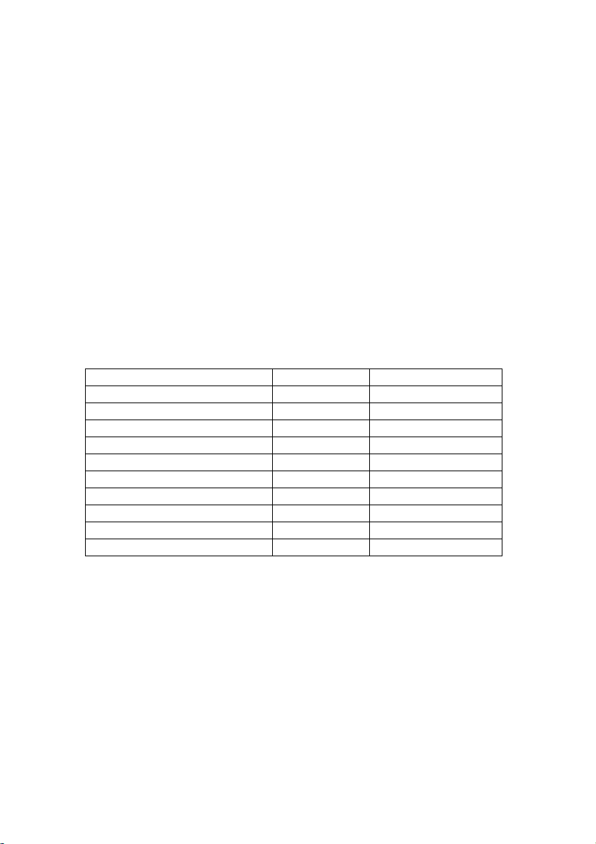
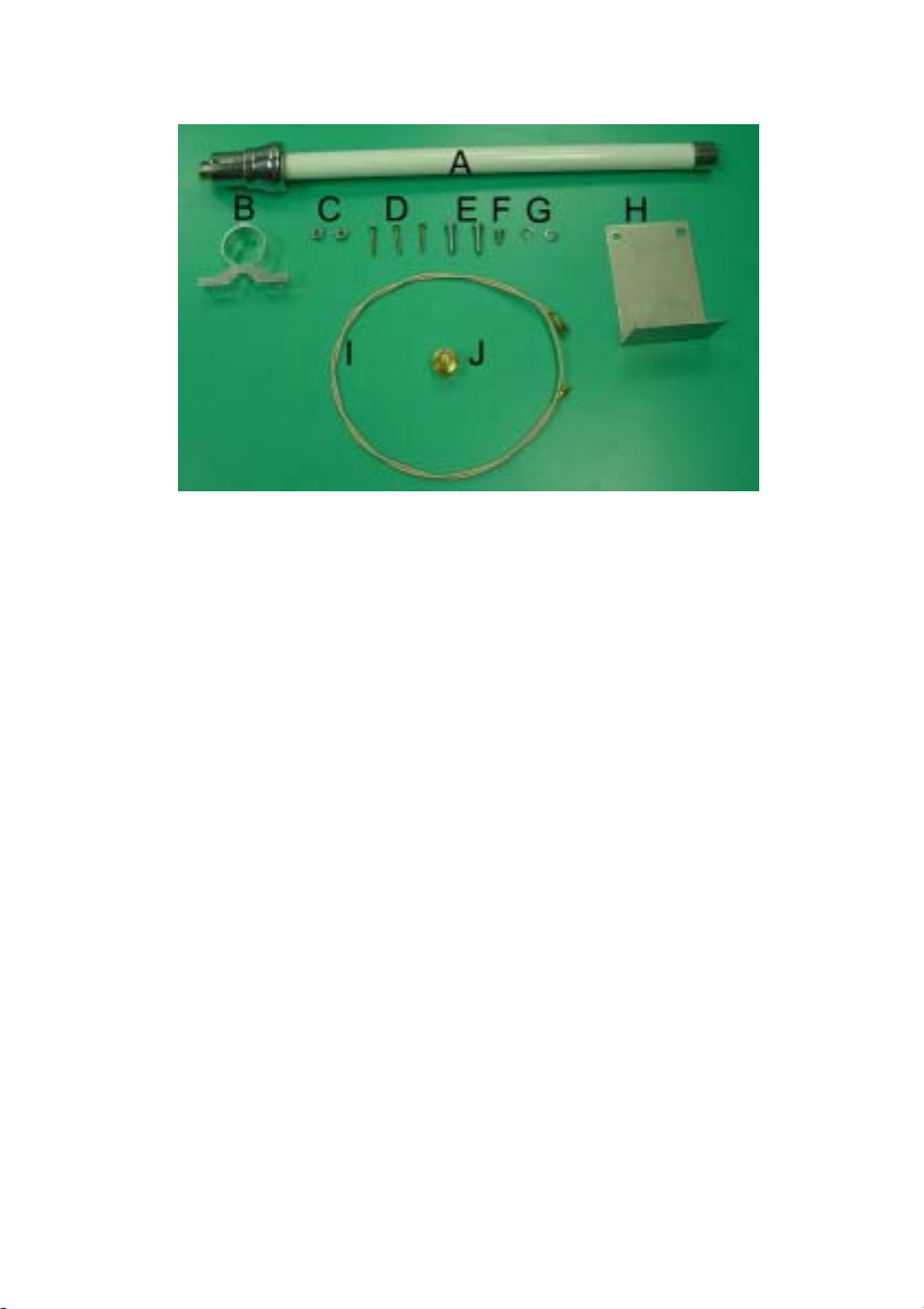
◆ Elements list (Figure 1-3)
Element Description Quantity Item
Omni-directional Antenna 1 A
Ferrules 1 B
Nut 2 C
Screw (Long) 3 D
Screw (medium) 2 E
Screw (short) 1 F
Lock-washers 5 G
Bracket 1 H
Cable 1 I
Jack 1 J
Page 5
5
Figure 1-3 Elements list
4-2. Mounting the Omni-directional Antenna
You can mount the 3dBi antenna to a ceiling for indoor use. This
antenna uses vertical polarization that is the most common type of
polarization for omni-directional antennas.
◆ Mounting to a ceiling
In most cases, these installations require a large coverage area.
Experience has shown that an omni-directional antenna mounting at
about 6 to 8 m eter (20 to 26 feet) will typicall y provide the best overall
coverage. Of cours e this also depends upon the height of the ceiling ,
material on the cei ling and ability to locate the antenna at this height.
The antenna should be placed in the center of the desired coverage
area. An open area will provide the best performance.
To mount the antenna to a ceiling proceed following steps:
1. Position the fer rule (item B in Figure 2-11) to the front of the brack et
(item H).
2. Place antenna m ounting scr ews (item F) through the s crew hole on
the bracket.
3. Use the lock – washers (item G) and nuts (item C) to secure the
bracket to the ferrule (item B).
Use a wrench to tight en t he nuts a nd ens ure t he ferrule will be f ixed
Page 6
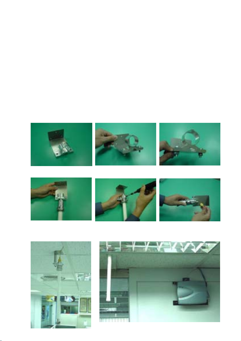
to the front of the bracket.
4. Feed the omni-directional antenna (item A) through the hole of the
ferrule (item B)
5. Push the antenna through the ferrule (item B) to the end. Place
screw (item E) to tighten the antenna.
Note
:
The hole of the antenna should be above the ferrule.(See
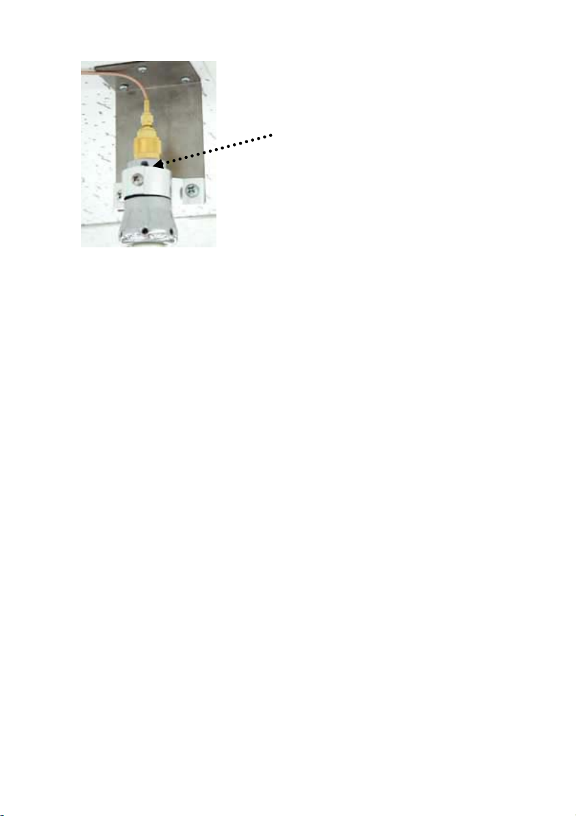
figure 1-4)
6. Attach t he cable (item I) and Jack (item J) to the connector on top
of the antenna.
7. Place 3 screws (item D) through the holes to fix the a ntenn a on the
ceiling.
8. Attach the other end of th e cable (i tem I) to the access point or the
PC card of the access point.
Step 4 Step 5 Step 6
Step 3Step 2Step 1
Step 7 Step 8
5
6
Page 7
The hole of the antenna
should be above the ferrul
Figure 1-4
e
7
Page 8
5. Installing the 7dBi Flat panel directional antenna
5-1. Hardware Description
The 7dBi flat panel antenna is a broadband antenna for the 2.4GHz
frequency band featuring a directional pattern with a normal gain of
7dBi. Before you start installing the antenna, verify the following items
in the antenna kits or in the product package.
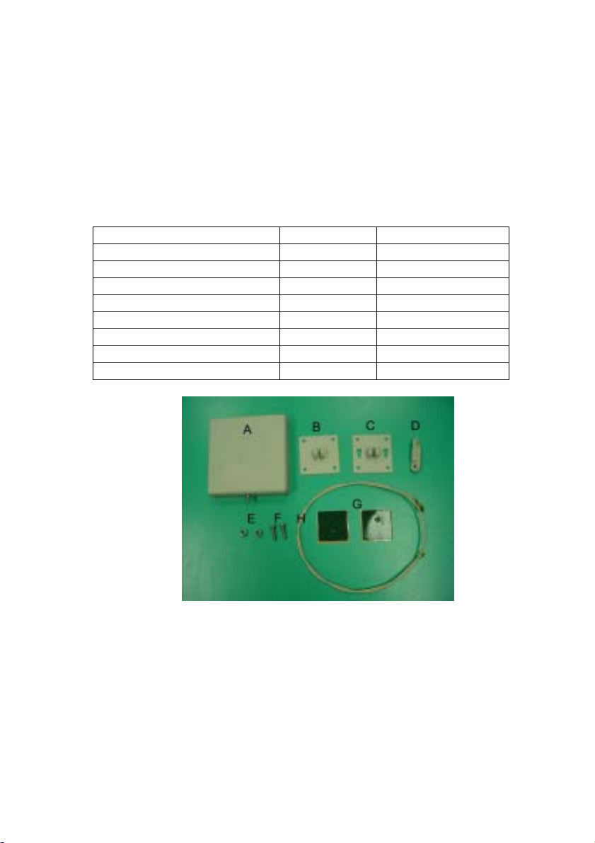
◆ Elements list (Figure 1-5)
Element Description Quantity Item
Flat Panel Antenna 1 A
Panel for Antenna 1 B
Panel for Wall 1 C
Strut 1 D
Nut 2 E
Screw 2 F
Gummed tape 2 G
Cable 1 H
Figure 1-5
5-2. Mounting the Flat panel directional Antenna
You can mount the 7dBi MHz antenna to a wall. Our package
has a 180° stand and you can adjust the best angle you want. This
antenna uses vertical polarization that is the most common type of
polarization for directional antennas.
8
Page 9

◆ Assembly the stand
To assembly the stand proceed following steps:
1. Put the strut (item D) through the hole of the panel for antenna
(item B) and panel for wall (item C).
2. Place 2 screws (item F) through these two holes.
3. Use two nuts (item E) to sec ure the panel for antenna (item B) and
panel for wall (item C). Complete set picture is in step 3
◆ Mounting to a wall
1. Stick or screw the stand on the wall.
2. Glue the on e-gummed tape in the panel for ante nna (item B) and
3. Attach the cable (item H) to the connector on the button of the
4. Attach the other end of the cable (it em H) to ac cess point or the pc
Step 1 Step 2 Step 3
To mount the antenna to a wall proceed following steps:
stick the flat panel antenna (item A) together. Make sure that the
connector of the flat panel antenna points to the ground.
antenna.
card of the access point.
9
Page 10

Step 1
Step 2
Step 3
Step 5
10
Step 4
Step 6
Page 11
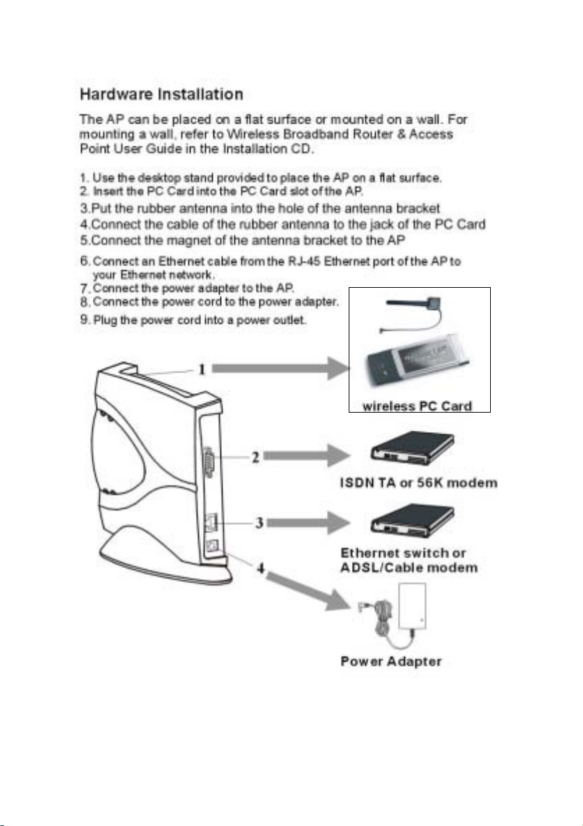
6.Installation Wireless PC card with one rubber antenna
11
Page 12

Appendix A Specifications
SL-2011CD General
Radio Data Rate 11, 5.5, 2 and 1 Mbps, Auto Fall-Back
11 Mbps – 150m
Range (open environment)
Operating Voltage 3.3V/5V
EMC Certifications FCC Part 15, ETSI 300/328
Compatibility
LED Indicator RF Link activity
Network Information
Network Architecture Support ad-hoc, peer-to-peer
Drivers Windows 95/98/ME/2000
Access Protocol CSMA/CA
Roaming IEEE802.11b compliant
Security 64/128-bit WEP data encryption
Radio
Frequency Band 2.412 – 2.462 GHz
Radio T ype Direct Sequence Spread
Modulation CCK (11, 5.5Mbps)
Operation Channels 11 for North America, 14 for Japan,
RF Output Power 13dBm + 2dBm
Antenna Integrated, with built-in diversity
Sensitivity @FER=0.08 11 Mbps < -83dBm
5.5 Mbps – 200m
2 Mbps – 250m
1 Mbps – 400m
Fully interoperable with IEEE802.11b
compliant products
networks and infrastructure
communications to wired Ethernet
networks via Access Point
Spectrum (DSSS)
DQPSK (2Mbps)
DBPSK (1Mbps)
13 for Europe, 2 for Spain, 4 for
France
5.5 Mbps < -86dBm
2 Mbps < -89dBm
1 Mbps < -91dBm
12
Page 13

Environmental
Temperature Range 0 to 50 C (operating)
-20 to 80 C (storage)
Humidity (non-condensing) 5% to 95% typical
Physical Specifications
Form Factor PCMCIA Type II PC Card
Dimensions 118(L) mm x 54(W) mm x 7.5(H) mm
Weight 40 g
13
Page 14

Specifications 3dBi Omni-directional Antenna
Mechanical
Size
W eight 370 g (13.05 ounces)
Material Guide pipe : Aluminum alloy
Mounting method Using our antenna kits to mount to a
Connector
Electrical
Frequency 2400-2485 MHz
Polarization Vertical
VSWR
Gain (dBi) 3
deg.
Specifications 7dBi Flat panel directional Antenna
Mechanical
Size
W eight 160 g (5.643 ounces)
Material ABS-PC
Mounting method Using our antenna kits to mount to a wall
Connector
Electrical
Frequency 2400-2485 MHz
Polarization Linear
VSWR
Gain (dBi) 7
Horz. 60° Beamwidth
deg.
Vert.
H 390 mm(15.35 inches)
Bracket : Aluminum alloy
ceiling
N-Female(reverse)
≦ 2.0 : 1
Horz. N/A Beamwidth
Vert.
60°
H 120 mm(4.72 inches), W 120mm(4.72inches),
D 27mm(1.063inches)
SMA female(unique)
≦ 2.0 : 1
60°
14
Page 15

Appendix B Regulatory Compliance Information
Radio Frequency Interference Requirements
FCC ID:NI3-SL-2011CD-ANT
CANADA:xxxxxxx
This device complies with Part 15 of FCC Rules and Canada RSS-210.
Operation is subject to the following conditions:
1. This device may not cause harmful interference.
2. This device must accept any interference received, including
interference that may cause undesired operation.
Interference Statement
Notice:The changes or modifications not expressly approved by
the party responsible for the compliance could void the
user’s authority to opera te the equipment.
This equipment has be en tested and f ound to com ply with the limits for
a Class B digital device pursuant to Part 15 of the FCC Rules and
Regulation. These lim its are designed to provide re asonable protection
against harmf ul interf erence in a resid ential i nstallation. This equipm ent
generates, uses, and can radiate radio frequency energy and, if not
installed and used in accordance with the instruction manual, may
cause harmful interf erence to ne arby TV’s, VCR’s, radi o, computers , or
other electronic devic es. To minimize or prev ent such interferenc e, this
equipment should not be placed or operated near these devices. If
interference is exp erienced , m oving the e quipm ent away from them will
often reduce or eliminate the interference.
However, there is no guarantee that interference will not occur in
a particular installation. If the equipment does cause harmful
interference to radio or television reception, which can be determined
by turning the equi pment off and on, the user is encouraged to try to
correct the interference by one or more of the following measures:
1.Re-orient or relocate the receiving antenna.
2.Increase the separation between the equipment and receiver.
3.Connect the equipment into an outlet on a circuit different from that
which the receiver is connected.
4.Consult the dealer or an experienced radio/TV technician for help.
15
 Loading...