

Page 1

CHAPTER 12
Introducing the SMT
This chapter describes how to access the SMT and provides an overview of its menus.
12.1 Introduction to the SMT
The NOA-3570’s SMT (System Management Terminal) is a menu-driven interface that you
can access from a terminal emulator through the console port or over a telnet connection. This
chapter shows you how to access the SMT (System Management Terminal) menus, how to
navigate the SMT and how to configure SMT menus.
12.2 Accessing the SMT via the Console Port
NOA-3570 User’s Guide
Make sure you have the physical connection properly set up as described in the Quick Start
Guide.
When configuring using the console port, you need a computer equipped with
communications software configured to the following parameters:
• VT100 terminal emulation.
• 9600 Baud.
• No parity, 8 data bits, 1 stop bit, flow control set to none.
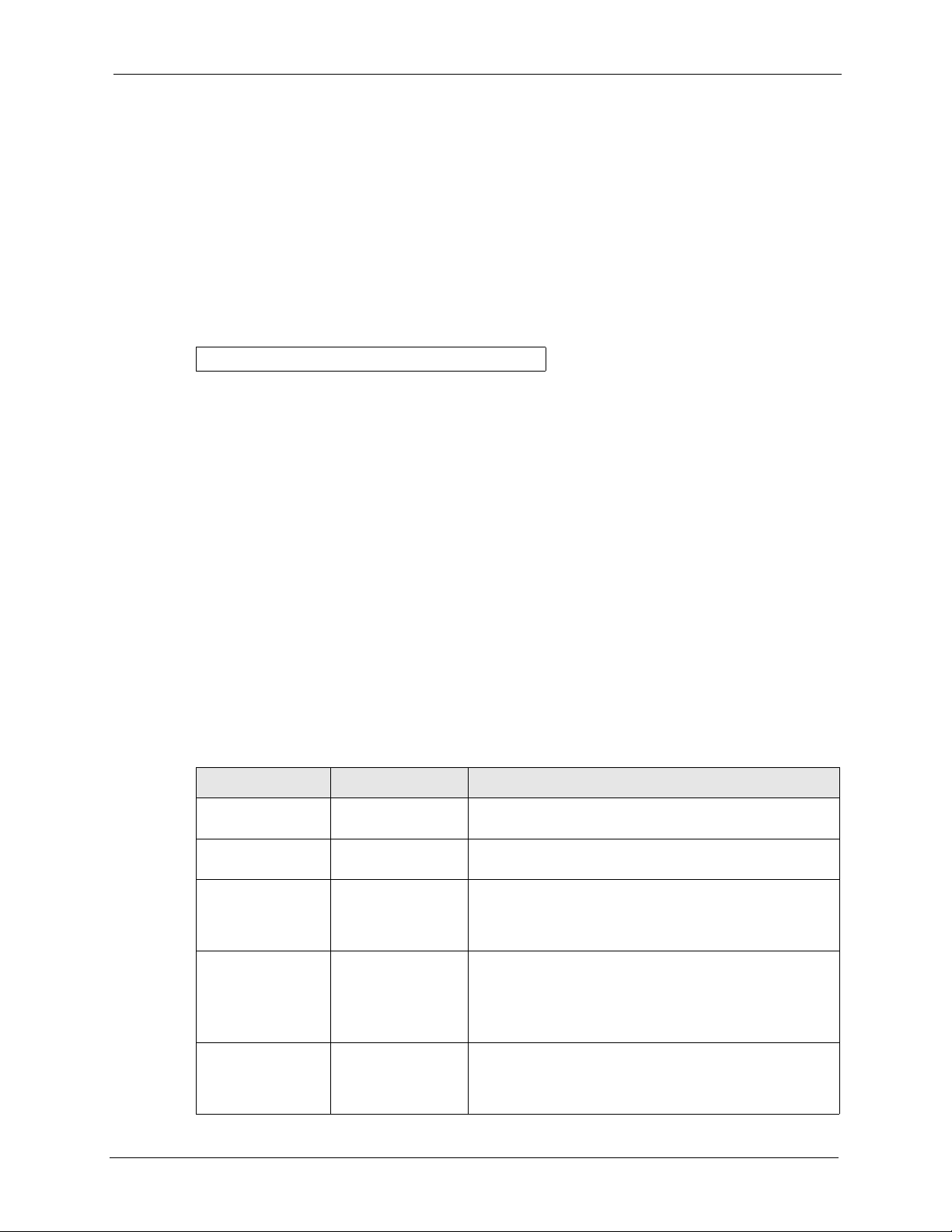
12.2.1 Initial Screen
When you turn on your NOA-3570, it performs several internal tests.
After the tests, the NOA-3570 asks you to press
[ENTER] to continue, as shown next.
Chapter 12 Introducing the SMT 131
Page 2

NOA-3570 User’s Guide
Figure 67 Initial Screen
Bootbase Version: V1.03 | 08/30/2004 16:28:56
RAM:Size = 64 Mbytes
FLASH: Intel 128M
ZyNOS Version: V3.50(HV.0)b4 | 01/21/2005 14:25:43
Press any key to enter debug mode within 3 seconds.
..........................................................
..
(Compressed)
Version: NOA-3570, start: 5012c030
Length: 46312C, Checksum: 4F98
Compressed Length: 161B28, Checksum: ED83
Copyright (c) 1994 - 2005 ZyXEL Communications Corp.
initialize ch =0, ethernet address: 00:A0:C5:62:B0:DB
initialize ch =1, ethernet address: 00:A0:C5:62:B0:DB
initialize ch =2, ethernet address: 00:A0:C5:62:B0:DC
initialize ch =3, ethernet address: 00:A0:C5:62:B0:DB
initialize ch =4, ethernet address: 00:A0:C5:62:B0:DB
initialize ch =5, ethernet address: 00:A0:C5:62:B0:DB
initialize ch =6, ethernet address: 00:A0:C5:62:B0:DB
initialize ch =7, ethernet address: 00:A0:C5:62:B0:DB
initialize ch =8, ethernet address: 00:A0:C5:62:B0:DC
initialize ch =9, ethernet address: 00:A0:C5:62:B0:DC
initialize ch =10, ethernet address: 00:A0:C5:62:B0:DC
initialize ch =11, ethernet address: 00:A0:C5:62:B0:DC
initialize ch =12, ethernet address: 00:A0:C5:62:B0:DC
Press ENTER to continue...
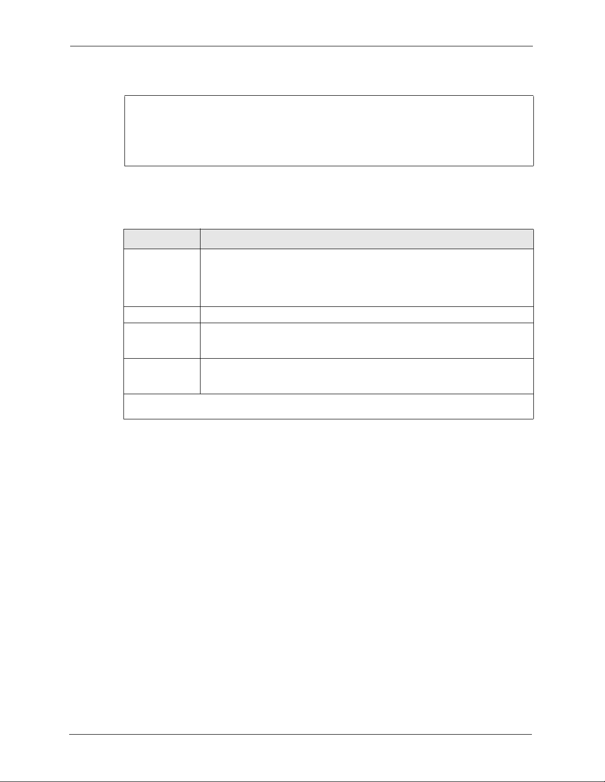
12.2.2 Entering the Password
The login screen appears after you press [ENTER], prompting you to enter the password, as
shown below.
For your first login, enter the default password “1234”. As you type the password, the screen
displays an “X” for each character you type.
Please note that if there is no activity for longer than five minutes after you log in, your NOA3570 will automatically log you out and display a blank screen. If you see a blank screen, press
[ENTER] to bring up the login screen again.
Figure 68 Password Screen
Enter Password : XXXX
132 Chapter 12 Introducing the SMT
Page 3
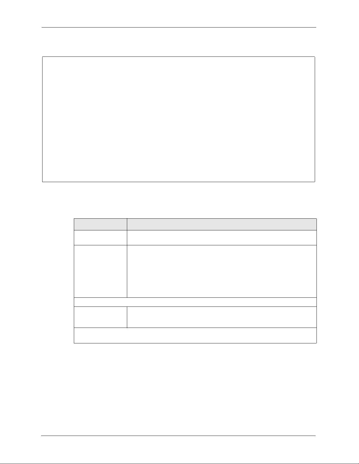
12.3 Accessing the SMT via Telnet
The following procedure details how to telnet into your NOA-3570.
1 In Windows, click Start (usually in the bottom left corner), Run and then type “telnet
192.168.1.2” (the default IP address) and click OK.
2 For your first login, enter the default password “1234”. As you type the password, the
screen displays an asterisk “*” for each character you type.
Figure 69 Login Screen
Password : xxxx
3 After entering the password you will see the main menu.
Please note that if there is no activity for longer than five minutes (default timeout period)
after you log in, your NOA-3570 will automatically log you out. You will then have to telnet
into the NOA-3570 again. You can use the web configurator or the CI commands to change
the inactivity time out period.
NOA-3570 User’s Guide
12.4 Navigating the SMT Interface
The SMT (System Management Terminal) is the interface that you use to configure your
NOA-3570.
Several operations that you should be familiar with before you attempt to modify the
configuration are listed in the table below.
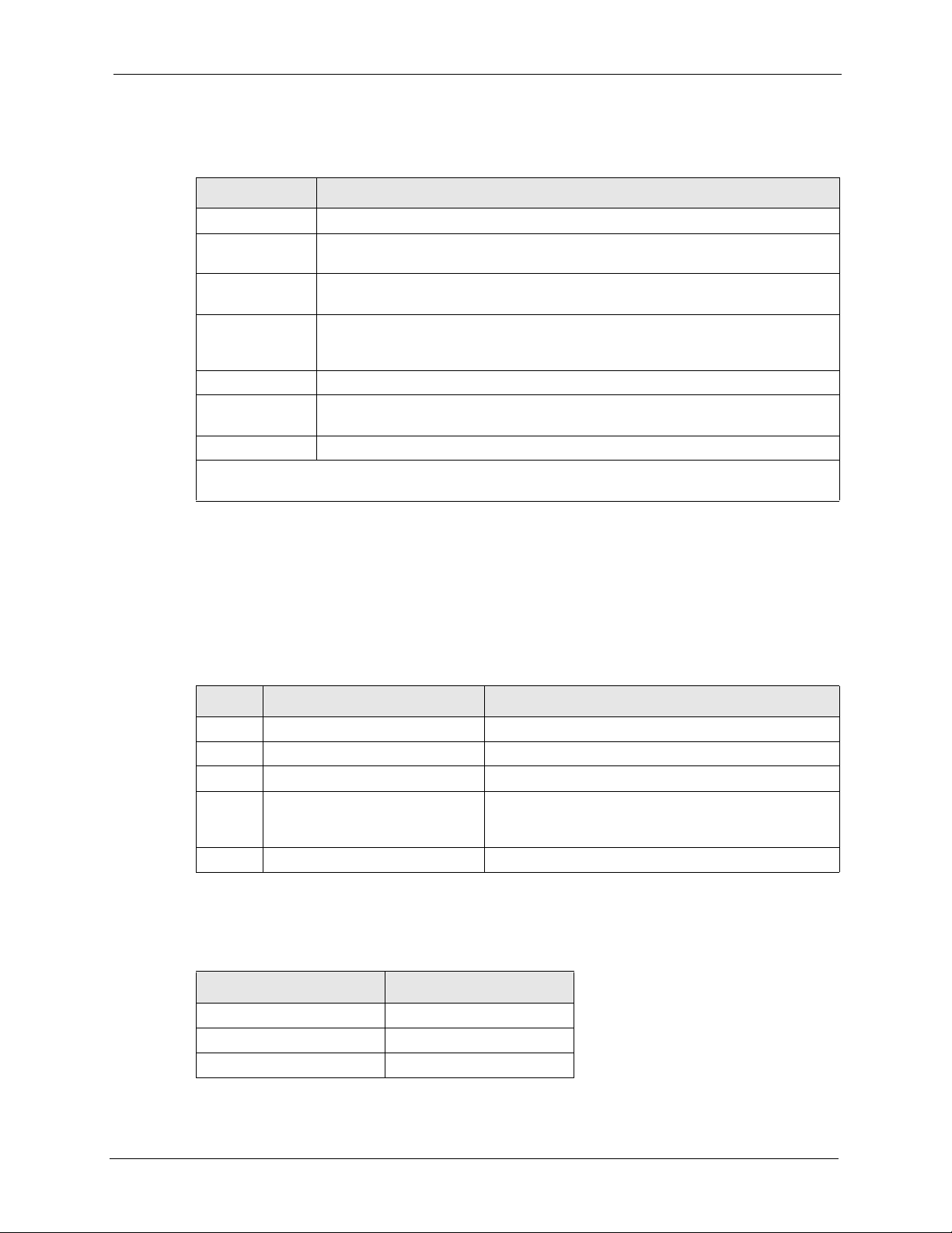
Table 43 Main Menu Commands NOA-3570
OPERATION KEYSTROKE DESCRIPTION
Move down to
another menu
Move up to a
previous menu
Move to a “hidden”
menu
Move the cursor [ENTER] or [UP]/
Entering information Type in or press
[ENTER] To move forward to a submenu, type in the number of the
[ESC] Press [ESC] to move back to the previous menu.
Press [SPACE BAR]
to change No to Yes
then press [ENTER].
[DOWN] arrow keys.
[SPACE BAR], then
press [ENTER].
desired submenu and press [ENTER].
Fields beginning with “Edit” lead to hidden menus and
have a default setting of No. Press [SPACE BAR] once to
change No to Yes, then press [ENTER] to go to the
“hidden” menu.
Within a menu, press [ENTER] to move to the next field.
You can also use the [UP]/[DOWN] arrow keys to move to
the previous and the next field, respectively.
When you are at the top of a menu, press the [UP] arrow
key to move to the bottom of a menu.
You need to fill in two types of fields. The first requires you
to type in the appropriate information. The second allows
you to cycle through the available choices by pressing
[SPACE BAR].
Chapter 12 Introducing the SMT 133
Page 4

NOA-3570 User’s Guide
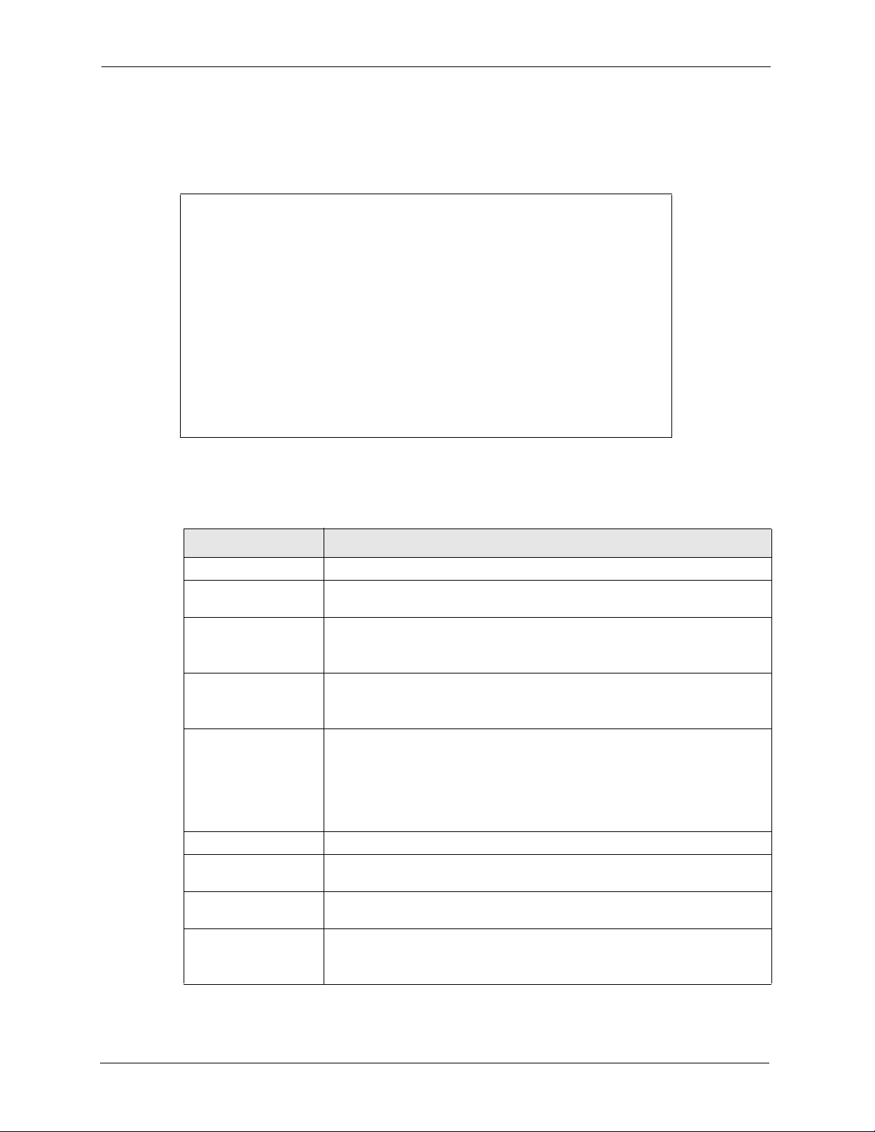
Table 43 Main Menu Commands NOA-3570
OPERATION KEYSTROKE DESCRIPTION
Required fields <?> or ChangeMe All fields with the symbol <?> must be filled in order to be
N/A fields <N/A> Some of the fields in the SMT will show a <N/A>. This
Save your
configuration
Exit the SMT Type 99, then press
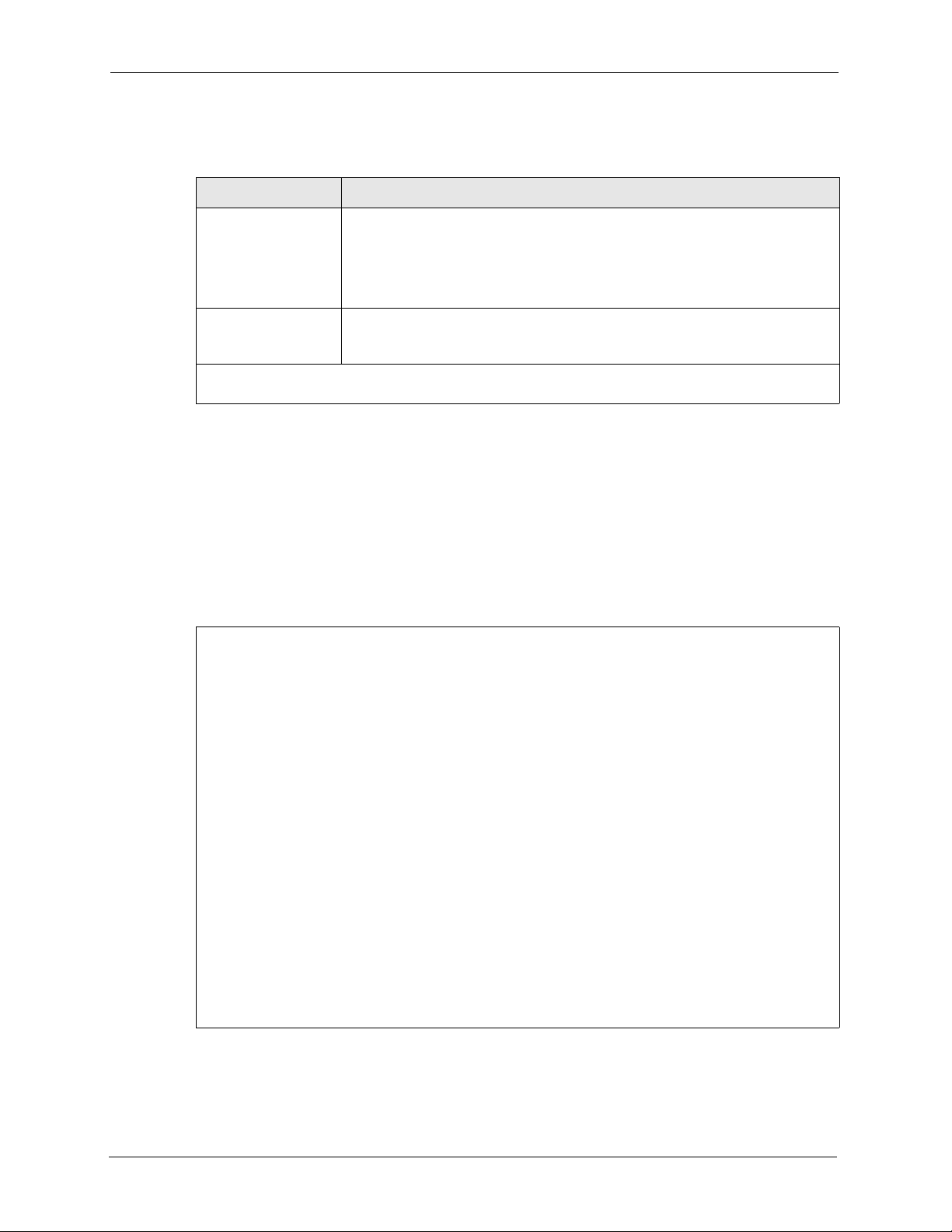
After you enter the password, the SMT displays the main menu, as shown next.
Figure 70 SMT Main Menu
able to save the new configuration.
All fields with ChangeMe must not be left blank in order to
be able to save the new configuration.
symbol refers to an option that is Not Applicable.
[ENTER] Save your configuration by pressing [ENTER] at the
message “Press ENTER to confirm or ESC to cancel”.
Saving the data on the screen will take you, in most cases
to the previous menu.
Make sure you save your settings in each screen that you
configure.
Type 99 at the main menu prompt and press [ENTER] to
[ENTER].
exit the SMT interface.
Copyright (c) 1994 - 2005 ZyXEL Communications Corp.
NOA-3570 Main Menu
Getting Started Advanced Management
1. General Setup 22. SNMP Configuration
3. LAN Setup 23. System Security
24. System Maintenance
Advanced Applications
14. Dial-in User Setup
16. VLAN Setup
99. Exit
Enter Menu Selection Number:
12.4.1 System Management Terminal Interface Summary
Table 44 Main Menu Summary NOA-3570
# MENU TITLE DESCRIPTION
1 General Setup Use this menu to set up your general information.
3 LAN Setup Use this menu to set up your LAN and WLAN connection.
14 Dial-in User Setup Use this menu to set up local user profiles on the NOA-3570.
16 VLAN Setup Use this menu to set up your VLAN ID.
22 SNMP Configuration Use this menu to set up SNMP related parameters.
134 Chapter 12 Introducing the SMT
Page 5

Table 44 Main Menu Summary NOA-3570
# MENU TITLE DESCRIPTION
23 System Security Use this menu to change your password and enable network user
24 System Maintenance This menu provides system status, diagnostics, software upload, etc.
99 Exit Use this to exit from SMT and return to a blank screen.
12.4.2 SMT Menus Overview
The following table gives you an overview of your NOA-3570’s various SMT menus.
Table 45 SMT Menus Overview NOA-3570
MENUS SUB MENUS
1 General Setup
3 LAN Setup 3.1 LAN Port Filter Setup
3.2 TCP/IP Setup
3.5 Wireless LAN Setup 3.5.1 WLAN MAC Address Filter
14 Dial-in User Setup 14.1 Edit Dial-in User Setup
16 VLAN Setup
22 SNMP Configuration
23 System Security 23.1 Change Password
23.2 RADIUS Server
23.4 IEEE802.1x
24 System Maintenance 24.1 System Status
24.2 System Information and
Console Port Speed
24.3 Log and Trace 24.3.1 View Error Log
24.4 Diagnostic
24.5 Backup Configuration
24.6 Restore Configuration
24.7 Upload Firmware 24.7.1 Upload System Firmware
24.8 Command Interpreter Mode
24.10 Time and Date Setting
NOA-3570 User’s Guide
authentication.
3.5.4 Bridge Link Configuration
24.2.1 System Information
24.2.2 Console Port Speed
24.3.2 Syslog Logging
24.3.4 Call-Triggering Packet
24.7.2 Upload System Configuration File
Chapter 12 Introducing the SMT 135
Page 6

NOA-3570 User’s Guide
12.5 Changing the System Password
Change the NOA-3570 default password by following the steps shown next.
1 From the main menu, enter 23 to display Menu 23 – System Security.
2 Enter 1 to display Menu 23.1 – System Security – Change Password as shown next.
3 Type your existing system password in the Old Password field, and press [ENTER].
Figure 71 Menu 23.1 System Security: Change Password
Menu 23.1 – System Security – Change Password
Old Password= ****
New Password= ?
Retype to confirm= ?
Enter here to CONFIRM or ESC to CANCEL:
4 Type your new system password in the New Password field (up to 30 characters), and
press [ENTER].
5 Re-type your new system password in the Retype to confirm field for confirmation and
press [ENTER].
Note that as you type a password, the screen displays an asterisk “*” for each character you
type.
136 Chapter 12 Introducing the SMT
Page 7

The chapter shows you the information on general setup.
13.1 General Setup
Menu 1 – General Setup contains administrative and system-related information (shown
next). The System Name field is for identification purposes. It is recommended you type your
computer's "Computer name".
The Domain Name entry is what is propagated to the DHCP clients on the LAN. While you
must enter the host name (System Name) on each individual computer, the domain name can
be assigned from the NOA-3570 via DHCP.
NOA-3570 User’s Guide
CHAPTER 13
General Setup
13.1.1 Procedure To Configure Menu 1
Enter 1 in the main menu to open Menu 1 – General Setup as shown next.
Figure 72 Menu 1 General Setup
Menu 1 - General Setup
System Name= NOA-3570
Domain Name=
First System DNS Server= From DHCP
IP Address= N/A
Second System DNS Server= None
IP Address= N/A
Third System DNS Server= None
IP Address= N/A
Chapter 13 General Setup 137
Page 8

NOA-3570 User’s Guide
Fill in the required fields. Refer to the following table for more information about these fields.
Table 46 Menu 1 General Setup
FIELD DESCRIPTION
System Name Choose a descriptive name for identification purposes. This name can be up to
Domain Name This is not a required field. Leave this field blank or enter the domain name
First/Second/Third
System DNS Server
IP Address Enter the IP addresses of the DNS servers. This field is available when you
When you have completed this menu, press [ENTER] at the prompt “Press ENTER to Confirm…” to
save your configuration, or press [
30 alphanumeric characters long. Spaces are not allowed, but dashes “-” and
underscores "_" are accepted.
here if you know it.
Press [SPACE BAR] to select From DHCP, User-Defined or None and press
[ENTER].
These fields are not available on all models.
select User-Defined in the field above.
ESC] at any time to cancel.
138 Chapter 13 General Setup
Page 9

This chapter shows you how to configure the LAN on your NOA-3570.
14.1 LAN Setup
This section describes how to configure the Ethernet using Menu 3 – LAN Setup. From the
main menu, enter 3 to display menu 3.
Figure 73 Menu 3 LAN Setup
NOA-3570 User’s Guide
CHAPTER 14
LAN Setup
Menu 3 - LAN Setup
2. TCP/IP Setup
5. Wireless LAN Setup
Enter Menu Selection Number:
14.2 TCP/IP Ethernet Setup
Use menu 3.2 to configure your NOA-3570 for TCP/IP.
To edit menu 3.2, enter 3 from the main menu to display Menu 3-LAN Setup. When menu 3
appears, press 2 and press [ENTER] to display Menu 3.2-TCP/IP Setup, as shown next
:
Chapter 14 LAN Setup 139
Page 10
NOA-3570 User’s Guide
Figure 74 Menu 3.2 TCP/IP Setup
Follow the instructions in the following table on how to configure the fields in this menu.
Table 47 Menu 3.2 TCP/IP Setup NOA-3570
FIELD DESCRIPTION
Menu 3.2 - TCP/IP Setup
IP Address Assignment= Static
IP Address= 192.168.1.2
IP Subnet Mask= 255.255.255.0
Gateway IP Address= 0.0.0.0
IP Address
Assignment
IP Address Enter the (LAN) IP address of your NOA-3570 in dotted decimal notation
IP Subnet Mask Your NOA-3570 will automatically calculate the subnet mask based on the IP
Gateway IP
Address
When you have completed this menu, press [ENTER] at the prompt “Press ENTER to Confirm…” to
save your configuration, or press [
Press [SPACE BAR] and then [ENTER] to select Dynamic to have the NOA-3570
obtain an IP address from a DHCP server. You must know the IP address assigned
to the NOA-3570 (by the DHCP server) to access the NOA-3570 again.
Select Static to give the NOA-3570 a fixed, unique IP address. Enter a subnet mask
appropriate to your network and the gateway IP address if applicable.
address that you assign. Unless you are implementing subnetting, use the subnet
mask computed by the NOA-3570.
Type the IP address of the gateway. The gateway is an immediate neighbor of your
NOA-3570 that will forward the packet to the destination. On the LAN, the gateway
must be a router on the same network segment as your NOA-3570.
14.3 Wireless LAN Setup
Use menu 3.5 to set up your NOA-3570 as the wireless access point. To edit menu 3.5, enter 3
from the main menu to display Menu 3 – LAN Setup. When menu 3 appears, press 5 and then
press [ENTER] to display Menu 3.5 – Wireless LAN Setup as shown next.
ESC] at any time to cancel.
140 Chapter 14 LAN Setup
Page 11

NOA-3570 User’s Guide
Figure 75 Menu 3.5 Wireless LAN Setup
Menu 3.5 - Wireless LAN Setup
WLAN Adapter= WLAN 1
Operating Mode= Access Point
Name (SSID)= ZyXEL
Hide Name (SSID)= No Edit MAC Address Filter= No
Channel ID= CH06 2437MHz Edit Roaming Configuration= No
RTS Threshold= 2432 Edit Br idge Link Configura tion= N/A
Frag. Threshold= 2432 Preamble= Long
WEP Encryption= Disable 802.11 Mode= Mixed
Default Key= N/A Max. Frame Burst= 650
Key1= N/A VLAN ID= 1
Key2= N/A Block Intra-BSS Traffic= No
Key3= N/A Output Power= 21dBm
Key4= N/A
Authen. Method= N/A
Press ENTER to Confirm or ESC to Cancel:
The following table describes the fields in this menu.
Table 48 Menu 3.5 Wireless LAN Setup NOA-3570
FIELD DESCRIPTION
WLAN Adapter Index Press [SPACE BAR] and select a wireless LAN adapter to configure.
Operating Mode Press [SPACE BAR] and select Access Point, Multiple ESS, Bridge /
Repeater or AP + Bridge.
Name (SSID) The SSID (Service Set IDentity) identifies the AP to which the wireless stations
associate. Wireless stations associating to the AP must have the same ESSID.
Enter a descriptive name of up to 32 printable 7-bit ASCII characters.
This field is only available when you select Access Point or AP + Bridge in the
Operating Mode field.
Hide Name (SSID) Press [SPACE BAR] and select Yes to hide the ESSID in the outgoing data
RTS Threshold Setting this attribute to zero turns on the RTS/CTS handshake. Enter a value
Frag. Threshold This is the maximum data fragment size that can be sent. Enter a value
WEP Encryption Select Disable to allow wireless stations to communicate with the access points
Default Key Enter the key number (1 to 4) in this field. Only one key can be enabled at any
frame so an intruder cannot obtain the ESSID through passive scanning.
between 0 and 2432.
between 800 and 2432.
without any data encryption.
Select 64-bit WEP or 128-bit WEP to enable data encryption.
one time. This key must be the same on the NOA-3570 and the wireless
stations to communicate.
Chapter 14 LAN Setup 141
Page 12

NOA-3570 User’s Guide
Table 48 Menu 3.5 Wireless LAN Setup NOA-3570
FIELD DESCRIPTION
Key 1 to Key 4 The WEP keys are used to encrypt data. Both the NOA-3570 and the wireless
Authen. Method Press [SPACE BAR] to select Auto, Open System Only or Shared Key Only
Edit MAC Address
Filter
Edit Roaming
Configuration
Edit Bridge Link
Configuration
Preamble Select a preamble type from the drop-down list menu. Choices are Long, Short
802.11 Mode Select 802.11b Only to allow only IEEE 802.11b compliant WLAN devices to
Max. Frame Burst Enable Maximum Frame Burst to help eliminate collisions in mixed-mode
VLAN ID The NOA-3570 supports IEEE 802.1 tagged VLAN for partioning a physical
Block Intra-BSS
Traffic
Output Power Level Press [SPACE BAR] to select the amount of power you want the NOA-3570 to
When you have completed this menu, press [ENTER] at the prompt “Press ENTER to confirm or ESC
to cancel” to save your configuration or press [ESC] to cancel and go back to the previous screen.
stations must use the same WEP key for data transmission.
If you chose 64-bit WEP in the WEP Encryption field, then enter any 5 ASCII
characters or 10 hexadecimal characters ("0-9", "A-F").
If you chose 128-bit WEP in the WEP Encryption field, then enter 13 ASCII
characters or 26 hexadecimal characters ("0-9", "A-F").
Note: Enter “0x” before the key to denote a hexadecimal key.
Don’t enter “0x” before the key to denote an ASCII key.
and press [ENTER].
This field is N/A if WEP is not activated.
If WEP encryption is activated, the default setting is Auto.
Press [SPACE BAR] to select Yes and press [ENTER] to display Menu 3.5.1 -
WLAN MAC Address Filter.
Press [SPACE BAR] to select Yes and press [ENTER] to display Menu 3.5.2 -
Roaming Configuration.
Use [SPACE BAR] to choose Ye s and press [ENTER] to go to Menu 3.5.4 -
Bridge Link Configuration.
and Dynamic. The default setting is Long.
See the section on preamble for more information.
associate with the NOA-3570.
Select 802.11g Only to allow only IEEE 802.11g compliant WLAN devices to
associate with the NOA-3570.
Select Mixed to allow either IEEE802.11b or IEEE802.11g compliant WLAN
devices to associate with the NOA-3570. The transmission rate of your NOA3570 might be reduced.
networks (networks with both IEEE 802.11g and IEEE 802.11b traffic) and
enhance the performance of both pure IEEE 802.11g and mixed IEEE 802.11b/
g networks. Maximum Frame Burst sets the maximum time, in microseconds,
that the NOA-3570 transmits IEEE 802.11g wireless traffic only.
Type the maximum frame burst between 0 and 1800 (650, 1000 or 1800
recommended). Enter 0 to disable this feature.
network into multiple logical networks. Enter a number from 1 to 4094 to set the
VLAN ID tag that the NOA-3570 adds to the Ethernet frames that this WLAN
adapter receives from wireless clients or other APs.
Press [SPACE BAR] to select Yes to only allow wireless stations to
communicate with the wired network, not with each other.
Press [SPACE BAR] to select No to allow wireless stations connected to the
NOA-3570 to communicate with each other.
use for the wireless signal. If there is a high density of APs within an area,
decrease the output power of the NOA-3570 to reduce interference with other
APs. The options are 21dBm, 19dBm, 17dBm or 15dBm.
142 Chapter 14 LAN Setup
Page 13

14.3.1 Configuring MAC Address Filter
Your NOA-3570 checks the MAC address of the wireless station device against a list of
allowed or denied MAC addresses. However, intruders could fake allowed MAC addresses so
MAC-based authentication is less secure than EAP authentication.
Follow the steps below to create the MAC address table on your NOA-3570.
1 From the main menu, enter 3 to open Menu 3 – LAN Setup.
2 Enter 5 to display Menu 3.5 – Wireless LAN Setup.
Figure 76 Menu 3.5 Wireless LAN Setup
Menu 3.5 - Wireless LAN Setup
Operating Mode= Access Point
Name (SSID)= ZyXEL
Hide Name (SSID)= No Edit MAC Address Filter= Yes
Channel ID= CH06 2437MHz Edit Roaming Configuration= No
RTS Threshold= 2432 Edit Bridge Link Configuration= N/A
Frag. Threshold= 2432 Preamble= Long
WEP Encryption= Disable 802.11 Mode= Mixed
Default Key= N/A Max. Frame Burst= 650
Key1= N/A Block Intra-BSS Traffic= No
Key2= N/A Output Power Level= 4
Key3= N/A
Key4= N/A
Authen. Method= N/A
NOA-3570 User’s Guide
Press ENTER to Confirm or ESC to Cancel:
Press Space Bar to Toggle.
3 Press [SPACE BAR] to select Access Point or AP + Bridge in the Operating Mode
field and press [ENTER].
4 In the Edit MAC Address Filter field, press [SPACE BAR] to select Yes and press
[ENTER]. Menu 3.5.1 – WLAN MAC Address Filter displays as shown next.
Chapter 14 LAN Setup 143
Page 14
NOA-3570 User’s Guide
Figure 77 Menu 3.5.1 WLAN MAC Address Filter
Menu 3.5.1 - WLAN MAC Address Filter
Active= No
Filter Action= Allowed Association
----------------------------------------------------------------------------- 1= 00:00:00:00:00:00 13= 00:00:00:00:00:00 25= 00:00:00:00:00:00
2= 00:00:00:00:00:00 14= 00:00:00:00:00:00 26= 00:00:00:00:00:00
3= 00:00:00:00:00:00 15= 00:00:00:00:00:00 27= 00:00:00:00:00:00
4= 00:00:00:00:00:00 16= 00:00:00:00:00:00 28= 00:00:00:00:00:00
5= 00:00:00:00:00:00 17= 00:00:00:00:00:00 29= 00:00:00:00:00:00
6= 00:00:00:00:00:00 18= 00:00:00:00:00:00 30= 00:00:00:00:00:00
7= 00:00:00:00:00:00 19= 00:00:00:00:00:00 31= 00:00:00:00:00:00
8= 00:00:00:00:00:00 20= 00:00:00:00:00:00 32= 00:00:00:00:00:00
9= 00:00:00:00:00:00 21= 00:00:00:00:00:00
10= 00:00:00:00:00:00 22= 00:00:00:00:00:00
11= 00:00:00:00:00:00 23= 00:00:00:00:00:00
12= 00:00:00:00:00:00 24= 00:00:00:00:00:00
----------------------------------------------------------------------------- Enter here to CONFIRM or ESC to CANCEL:
The following table describes the fields in this menu.
Table 49 Menu 3.5.1 WLAN MAC Address Filter NOA-3570
FIELD DESCRIPTION
Active To enable MAC address filtering, press [SPACE BAR] to select Yes and press
[ENTER].
Filter Action Define the filter action for the list of MAC addresses in the MAC address filter
MAC Address Filter
1..32 Enter the MAC addresses (in XX:XX:XX:XX:XX:XX format) of the client
When you have completed this menu, press [ENTER] at the prompt “Press ENTER to confirm or ESC
to cancel” to save your configuration or press [ESC] to cancel and go back to the previous screen.
table.
To deny access to the NOA-3570, press [SPACE BAR] to select Deny
Association and press [ENTER]. MAC addresses not listed will be allowed to
access the router.
The default action, Allowed Association, permits association with the NOA-
3570. MAC addresses not listed will be denied access to the router.
computers that are allowed or denied access to the NOA-3570 in these address
fields.
14.3.2 Configuring Roaming
Follow the steps below to configure roaming on your NOA-3570.
1 From the main menu, enter 3 to open Menu 3 – LAN Setup.
2 Enter 5 to display Menu 3.5 – Wireless LAN Setup.
144 Chapter 14 LAN Setup
Page 15

NOA-3570 User’s Guide
Figure 78 Menu 3.5 Wireless LAN Setup
Menu 3.5 - Wireless LAN Setup
Operating Mode= Access Point
Name (SSID)= ZyXEL
Hide Name (SSID)= No Edit MAC Address Filter= No
Channel ID= CH06 2437MHz Edit Roaming Configuration= No
RTS Threshold= 2432 Edit Bridge Link Configuration= N/A
Frag. Threshold= 2432 Preamble= Long
WEP Encryption= Disable 802.11 Mode= Mixed
Default Key= N/A Max. Frame Burst= 650
Key1= N/A Block Intra-BSS Traffic= No
Key2= N/A Output Power Level= 4
Key3= N/A
Key4= N/A
Authen. Method= N/A
Press ENTER to Confirm or ESC to Cancel:
3 In the Operating Mode field, press [SPACE BAR] to select AP or AP + Bridge and
press [ENTER].
4 Move the cursor to the Edit Roaming Configuration field. Press [SPACE BAR] to
select Yes and press [ENTER]. Menu 3.5.2 – Roaming Configuration displays as
shown next.
Figure 79 Menu 3.5.2 - Roaming Configuration
Menu 3.5.2 - Roaming Configuration
Active= No
Port #= N/A
The following table describes the fields in this menu.
Chapter 14 LAN Setup 145
Page 16
NOA-3570 User’s Guide
Table 50 Menu 3.5.2 - Roaming Configuration NOA-3570
FIELD DESCRIPTION
Active Press [SPACE BAR] to select Yes from the drop-down list box to enable
roaming on the NOA-3570 if you have two or more NOA-3570s on the same
subnet.
Note: All APs on the same subnet and the wireless stations must
have the same SSID to allow roaming.
Port Type the port number to communicate roaming information between access
points. The port number must be the same on all access points. The default is
3517. Make sure this port is not used by other services.
When you have completed this menu, press [ENTER] at the prompt “Press ENTER to confirm or ESC
to cancel” to save your configuration or press [ESC] to cancel and go back to the previous screen.
14.3.3 Configuring Bridge Link
Follow the steps below to configure bridge link on your NOA-3570.
1 From the main menu, enter 3 to open Menu 3 – LAN Setup.
2 Enter 5 to display Menu 3.5 – Wireless LAN Setup.
Figure 80 Menu 3.5 Wireless LAN Setup
Menu 3.5 - Wireless LAN Setup
Operating Mode= Bridge / Repeater
Name (SSID)= N/A
Hide Name (SSID)= N/A Edit MAC Address Filter= N/A
Channel ID= CH06 2437MHz Edit Roaming Configuration= N/A
RTS Threshold= 2432 Edit Bridge Link Configuration= Yes
Frag. Threshold= 2432 Preamble= Long
WEP Encryption= Disable 802.11 Mode= Mixed
Default Key= N/A Max. Frame Burst= 650
Key1= N/A Block Intra-BSS Traffic= No
Key2= N/A Output Power Level= 4
Key3= N/A
Key4= N/A
Authen. Method= N/A
Press ENTER to Confirm or ESC to Cancel:
Press Space Bar to Toggle.
3 In the Operating Mode field, press [SPACE BAR] to select Bridge / Repeater or AP
+ Bridge and press [ENTER].
146 Chapter 14 LAN Setup
Page 17
NOA-3570 User’s Guide
4 Move the cursor to the Edit Bridge Link Configuration field. Press [SPACE BAR] to
select Yes and press [ENTER]. Menu 3.5.4 – Bridge Link Configuration displays as
shown next.
Figure 81 Menu 3.5.4 - Bridge Link Configuration
Menu 3.5.4 - Bridge Link Configuration
Enable Link 1= No Peer MAC Address= 00:00:00:00:00:00
PSK= N/A
Enable Link 2= No Peer MAC Address= 00:00:00:00:00:00
PSK= N/A
Enable Link 3= No Peer MAC Address= 00:00:00:00:00:00
PSK= N/A
Enable Link 4= No Peer MAC Address= 00:00:00:00:00:00
PSK= N/A
Enable Link 5= No Peer MAC Address= 00:00:00:00:00:00
PSK= N/A
Enable WDS Security= No
Press ENTER to Confirm or ESC to Cancel:
The following table describes the fields in this menu.
Table 51 Menu 3.5.4 Bridge Link Configuration NOA-3570
FIELD DESCRIPTION
Enable Link 1-6 Press [SPACE BAR] to select Yes or No and press [ENTER].
Peer MAC Address Type the MAC address of a wireless bridge in valid MAC address format, that
Enable WDS Security A Wireless Distribution System (WDS) is a wireless connection between two or
is, six hexadecimal character pairs, for example, 12:34:56:78:9a:bc.
more APs.
Press [SPACE BAR] to select Yes to use TKIP to encrypt traffic on the WDS
between APs.
When you enable WDS security, type a Pre-Shared Key (PSK) for each link.
Note: Other wireless bridges must use the same encryption
method to enable WDS security.
PSK When you enable WDS, type a Pre-Shared Key (PSK) for each link. The pre-
shared key can be from 8 to 63 case-sensitive ASCII characters (including
spaces and symbols).
When you have completed this menu, press [ENTER] at the prompt “Press ENTER to confirm or ESC
to cancel” to save your configuration or press [ESC] to cancel and go back to the previous screen.
Chapter 14 LAN Setup 147
Page 18

NOA-3570 User’s Guide
148 Chapter 14 LAN Setup
Page 19

This chapter shows you how to create user accounts on the NOA-3570.
15.1 Dial-in User Setup
By storing user profiles locally, your NOA-3570 is able to authenticate wireless users without
interacting with a network RADIUS server.
Follow the steps below to set up user profiles on your NOA-3570.
From the main menu, enter 14 to display Menu 14 - Dial-in User Setup.
NOA-3570 User’s Guide
CHAPTER 15
Dial-in User Setup
Figure 82 Menu 14- Dial-in User Setup
Menu 14 - Dial-in User Setup
1. ________ 9. ________ 17. ________ 25. ________
2. ________ 10. ________ 18. ________ 26. ________
3. ________ 11. ________ 19. ________ 27. ________
4. ________ 12. ________ 20. ________ 28. ________
5. ________ 13. ________ 21. ________ 29. ________
6. ________ 14. ________ 22. ________ 30. ________
7. ________ 15. ________ 23. ________ 31. ________
8. ________ 16. ________ 24. ________ 32. ________
Enter Menu Selection Number:
Type a number and press [ENTER] to edit the user profile.
Figure 83 Menu 14.1- Edit Dial-in User
Menu 14.1 - Edit Dial-in User
User Name= test
Active= Yes
Password= ********
Press ENTER to Confirm or ESC to Cancel:
Leave name field blank to delete profile
The following table describes the fields in this screen.
Chapter 15 Dial-in User Setup 149
Page 20
NOA-3570 User’s Guide
Table 52 Menu 14.1- Edit Dial-in User NOA-3570
FIELD DESCRIPTION
User Name Enter a username up to 31 alphanumeric characters long for this user profile.
Active Press [SPACE BAR] to select Yes and press [ENTER] to enable the user
Password Enter a password up to 31 characters long for this user profile.
When you have completed this menu, press [ENTER] at the prompt “Press ENTER to confirm or ESC
to cancel” to save your configuration or press [ESC] to cancel and go back to the previous screen.
This field is case sensitive.
profile.
150 Chapter 15 Dial-in User Setup
Page 21
This chapter explains VLAN setup menu 16. Refer to the web configurator VLAN chapter for
background information on VLAN.
16.1 VLAN Setup
To setup VLAN, select option 16 from the main menu to open Menu 16 – VLAN Setup as
shown next.
Figure 84 Menu 16 VLAN Setup
Menu 16 - VLAN Setup
NOA-3570 User’s Guide
CHAPTER 16
VLAN Setup
VLAN Tagging= Yes
Native VLAN ID= 1
The following table describes the fields in this menu.
Table 53 Menu 16 VLAN Setup
FIELD DESCRIPTION
VLAN Tagging To enable VLAN tagging, press [SPACE BAR] to select Yes and press
[ENTER].
Native VLAN ID This field is activated only when you select Yes in the VLAN Tagging field.
Enter a number from 1 to 4094 to specify the ID of the management VLAN.
Your management computer must belong to this VLAN group in order to
manage the NOA-3570. This can be done in the following ways:
• The management computer could be a wireless client of the NOA-3570 if
the NOA-3570’s WLAN adapter is set to add the add the management
VLAN ID tag to Ethernet frames received from wireless clients.
• The management computer could be on the wired network, behind a
VLAN-aware switch that is configured to add the management VLAN ID
tag to Ethernet frames from the computer before sending them to NOA-
3570.
Note: Mail and FTP servers must have the same management
VLAN ID to communicate with the NOA-3570.
When you have completed this menu, press [ENTER] at the prompt “Press ENTER to confirm or ESC
to cancel” to save your configuration or press [ESC] to cancel and go back to the previous screen.
Chapter 16 VLAN Setup 151
Page 22

NOA-3570 User’s Guide
152 Chapter 16 VLAN Setup
Page 23
This chapter explains SNMP Configuration menu 22.
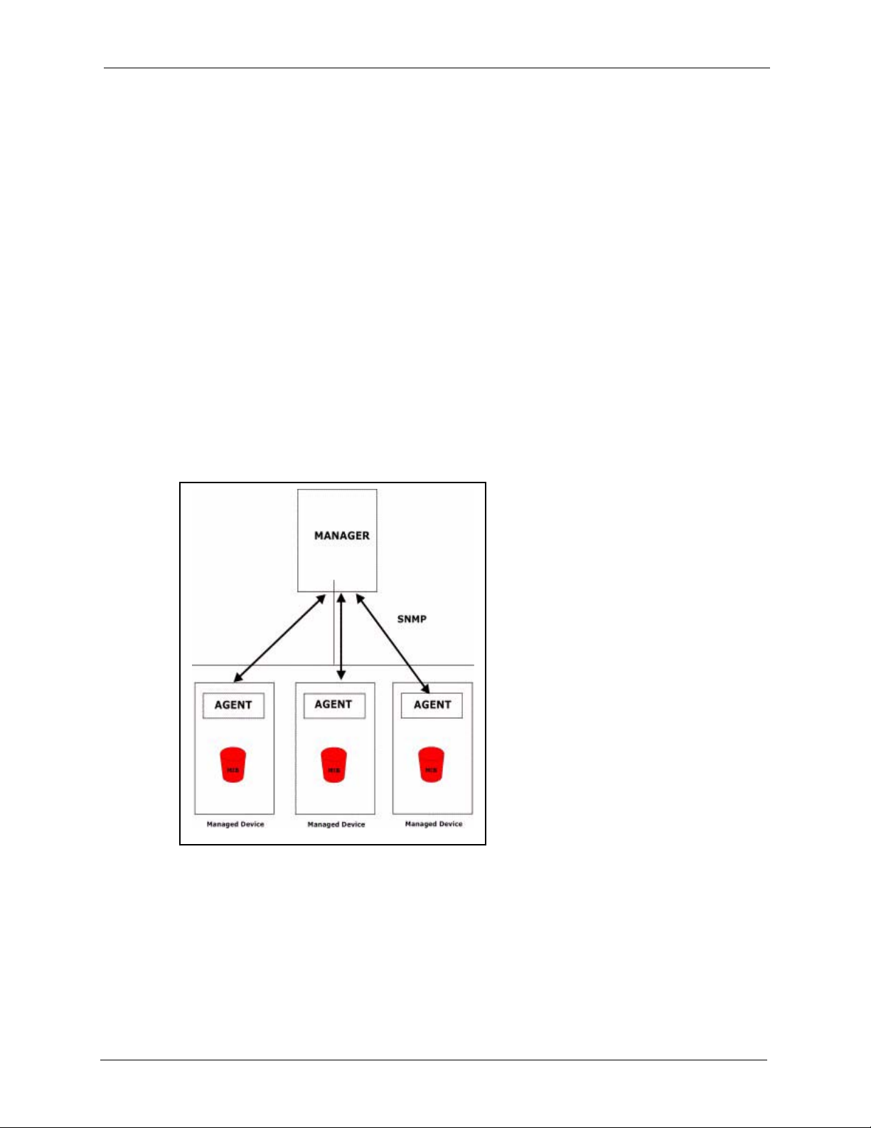
17.1 About SNMP
Simple Network Management Protocol is a protocol used for exchanging management
information between network devices. SNMP is a member of the TCP/IP protocol suite. Your
NOA-3570 supports SNMP agent functionality, which allows a manager station to manage
and monitor the NOA-3570 through the network. The NOA-3570 supports SNMP version one
(SNMPv1) and version two c (SNMPv2c). The next figure illustrates an SNMP management
operation. SNMP is only available if TCP/IP is configured.
NOA-3570 User’s Guide
CHAPTER 17
SNMP Configuration
Figure 85 SNMP Management Model
An SNMP managed network consists of two main components: agents and a manager.
An agent is a management software module that resides in a managed device (the NOA-3570).
An agent translates the local management information from the managed device into a form
compatible with SNMP. The manager is the console through which network administrators
perform network management functions. It executes applications that control and monitor
managed devices.
Chapter 17 SNMP Configuration 153
Page 24

NOA-3570 User’s Guide
The managed devices contain object variables/managed objects that define each piece of
information to be collected about a device. Examples of variables include the number of
packets received, node port status etc. A Management Information Base (MIB) is a collection
of managed objects. SNMP allows a manager and agents to communicate for the purpose of
accessing these objects.
SNMP itself is a simple request/response protocol based on the manager/agent model. The
manager issues a request and the agent returns responses using the following protocol
operations:
• Get - Allows the manager to retrieve an object variable from the agent.
• GetNext - Allows the manager to retrieve the next object variable from a table or list
within an agent. In SNMPv1, when a manager wants to retrieve all elements of a table
from an agent, it initiates a Get operation, followed by a series of GetNext operations.
• Set - Allows the manager to set values for object variables within an agent.
• Trap - Used by the agent to inform the manager of some events.
17.2 Supported MIBs
The NOA-3570 supports RFC-1215 and MIB II as defined in RFC-1213. The focus of the
MIBs is to let administrators collect statistic data and monitor status and performance.
17.3 SNMP Configuration
To configure SNMP, select option 22 from the main menu to open Menu 22 – SNMP
Configuration as shown next. The “community” for Get, Set and Trap fields is SNMP
terminology for password.
Figure 86 Menu 22 SNMP Configuration
Menu 22 - SNMP Configuration
SNMP:
Get Community= public
Set Community= public
Trusted Host= 0.0.0.0
Trap:
Community= public
Destination= 0.0.0.0
Press ENTER to Confirm or ESC to Cancel:
The following table describes the SNMP configuration parameters.
154 Chapter 17 SNMP Configuration
Page 25
NOA-3570 User’s Guide
Table 54 Menu 22 SNMP Configuration NOA-3570
FIELD DESCRIPTION
SNMP:
Get Community Type the Get Community, which is the password for the incoming Get- and
GetNext requests from the management station.
Set Community Type the Set Community, which is the password for incoming Set requests from
Trusted Host If you enter a trusted host, your NOA-3570 will only respond to SNMP messages
Trap:
Community Type the trap community, which is the password sent with each trap to the SNMP
Destination Type the IP address of the station to send your SNMP traps to.
When you have completed this menu, press [ENTER] at the prompt “Press ENTER to confirm or ESC
to cancel” to save your configuration or press [ESC] to cancel and go back to the previous screen.
the management station.
from this address. A blank (default) field means your NOA-3570 will respond to all
SNMP messages it receives, regardless of source.
manager.
17.4 SNMP Traps
The NOA-3570 will send traps to the SNMP manager when any one of the following events
occurs:
Table 55 SNMP Traps NOA-3570
TRAP # TRAP NAME DESCRIPTION
1 coldStart (defined in RFC-1215) A trap is sent after booting (power on).
2 warmStart (defined in RFC-1215) A trap is sent after booting (software reboot).
3 linkUp (defined in RFC-1215) A trap is sent when the port is up.
4 authenticationFailure (defined in
RFC-1215)
6 linkDown (defined in RFC-1215) A trap is sent when the port is down.
The following table maps the physical port and encapsulation to the interface type,
Table 56 Ports and Interface Types NOA-3570
PHYSICAL PORT/ENCAP INTERFACE TYPE
A trap is sent to the manager when receiving any SNMP
get or set requirements with wrong community
(password).
WLAN 1 enet0
Ethernet port enet1
WLAN 2 enet2
Chapter 17 SNMP Configuration 155
Page 26

NOA-3570 User’s Guide
156 Chapter 17 SNMP Configuration
Page 27

This chapter describes how to configure the system security on the NOA-3570.
18.1 System Security
You can configure the system password, an external RADIUS server and 802.1x in this menu.
18.1.1 System Password
Figure 87 Menu 23 System Security
Menu 23 - System Security
NOA-3570 User’s Guide
CHAPTER 18
System Security
1. Change Password
2. RADIUS Server
4. IEEE802.1x
Enter Menu Selection Number:
You should change the NOA-3570’s management password. Refer to the section on changing
the system password in the Introducing the SMT chapter for details. If you forget your
password you have to restore the default configuration file. Refer to the section on resetting
the NOA-3570 in the Introducing the Web Configurator chapter.
18.1.2 Configuring External RADIUS Server
Enter 23 in the main menu to display Menu 23 – System Security.
Figure 88 Menu 23 System Security
Menu 23 - System Security
1. Change Password
2. RADIUS Server
4. IEEE802.1x
Enter Menu Selection Number:
Chapter 18 System Security 157
Page 28
NOA-3570 User’s Guide
From Menu 23- System Security, enter 2 to display Menu 23.2 – System Security –
RADIUS Server as shown next.
Figure 89 Menu 23.2 System Security: RADIUS Server
Menu 23.2 - System Security - RADIUS Server
Authentication Server:
Active= No
Server Address= 0.0.0.0
Port #= 1812
Shared Secret= ********
Accounting Server:
Active= No
Server Address= 0.0.0.0
Port #= 1813
Shared Secret= ********
Press ENTER to Confirm or ESC to Cancel:
The following table describes the fields in this menu.
Table 57 Menu 23.2 System Security: RADIUS Server NOA-3570
FIELD DESCRIPTION
Authentication Server
Active Press [SPACE BAR] to select Yes and press [ENTER] to enable user
authentication through an external authentication server.
Server Address To use an external authentication server, enter its IP address in dotted
decimal notation.
Enter 127.0.0.1 to use the internal authentication server.
Port The default port of the RADIUS server for authentication is 1812.
You need not change this value unless your network administrator instructs
you to do so with additional information.
Shared Secret To use an external authentication server, specify a password (up to 31
alphanumeric characters) as the key to be shared between the external
authentication server and the access points.
The key is not sent over the network. This key must be the same on the
external authentication server and NOA-3570.
Enter 1234 to use the internal authentication server.
Accounting Server
Active Press [SPACE BAR] to select Yes and press [ENTER] to enable user
authentication through an external accounting server.
Server Address Enter the IP address of the external accounting server in dotted decimal
notation.
Port The default port of the RADIUS server for accounting is 1813.
You need not change this value unless your network administrator instructs
you to do so with additional information.
158 Chapter 18 System Security
Page 29
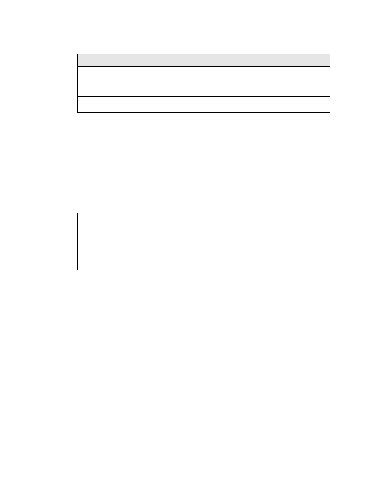
Table 57 Menu 23.2 System Security: RADIUS Server NOA-3570
FIELD DESCRIPTION
Shared Secret Specify a password (up to 31 alphanumeric characters) as the key to be
When you have completed this menu, press [ENTER] at the prompt “Press ENTER to confirm or ESC
to cancel” to save your configuration or press [ESC] to cancel and go back to the previous screen.
18.1.3 802.1x
The IEEE 802.1x standards outline enhanced security methods for both the authentication of
wireless stations and encryption key management.
Follow the steps below to enable EAP authentication on your NOA-3570.
1 From the main menu, enter 23 to display Menu23 – System Security.
Figure 90 Menu 23 System Security
NOA-3570 User’s Guide
shared between the external accounting server and the access points.
The key is not sent over the network. This key must be the same on the
external accounting server and NOA-3570.
Menu 23 - System Security
1. Change Password
2. RADIUS Server
4. IEEE802.1x
Enter Menu Selection Number:
2 Enter 4 to display Menu 23.4 – System Security – IEEE802.1x.
Chapter 18 System Security 159
Page 30

NOA-3570 User’s Guide
Figure 91 Menu 23.4 System Security: IEEE802.1x
Wireless Port Control= Authentication Required
ReAuthentication Timer (in second)= 1800
Idle Timeout (in second)= 3600
Key Management Protocol= 802.1x
Dynamic WEP Key Exchange= 128-bit WEP
PSK= N/A
WPA Mixed Mode= N/A
WPA Group Key Update Timer= N/A
Authentication Databases= Local User Database Only
The following table describes the fields in this menu.
Menu 23.4 - System Security - IEEE802.1x
Press ENTER to Confirm or ESC to Cancel:
Press Space Bar to Toggle.
Table 58 Menu 23.4 System Security: IEEE802.1x NOA-3570
FIELD DESCRIPTION
Wireless Port Control Press [SPACE BAR] and select a security mode for the wireless LAN access.
Select No Authentication Required to allow any wireless stations access to
your wired network without entering usernames and passwords. This is the
default setting.
Selecting Authentication Required means wireless stations have to enter
usernames and passwords before access to the wired network is allowed.
Select No Access Allowed to block all wireless stations access to the wired
network.
The following fields are not available when you select No Authentication
Required or No Access Allowed.
ReAuthentication
Timer (in second)
Idle Timeout (in
second)
Key Management
Protocol
Specify how often a client has to re-enter username and password to stay
connected to the wired network.
This field is activated only when you select Authentication Required in the
Wireless Port Control field. Enter a time interval between 10 and 9999 (in
seconds). The default time interval is 1800 seconds (or 30 minutes).
The NOA-3570 automatically disconnects a client from the wired network after
a period of inactivity. The client needs to enter the username and password
again before access to the wired network is allowed.
This field is activated only when you select Authentication Required in the
Wireless Port Control field. The default time interval is 3600 seconds (or 1
hour).
Press [SPACE BAR] to select 802.1x, WPA or WPA-PSK and press [ENTER].
160 Chapter 18 System Security
Page 31

Table 58 Menu 23.4 System Security: IEEE802.1x NOA-3570
FIELD DESCRIPTION
NOA-3570 User’s Guide
Dynamic WEP Key
Exchange
PSK Type a pre-shared key from 8 to 63 case-sensitive ASCII characters (including
WPA Mixed Mode Select Enable to activate WPA mixed mode. Otherwise, select Disable and
WPA Group Key
Update Timer
Authentication
Databases
When you have completed this menu, press [ENTER] at the prompt “Press ENTER to confirm or ESC
to cancel” to save your configuration or press [ESC] to cancel and go back to the previous screen.
This field is activated only when you select Authentication Required in the
Wireless Port Control field. Also set the Authentication Databases field to
RADIUS Only. Local user database may not be used.
Select Disable to allow wireless stations to communicate with the access
points without using Dynamic WEP Key Exchange.
Select 64-bit WEP or 128-bit WEP to enable data encryption.
Up to 32 stations can access the NOA-3570 when you configure Dynamic WEP
Key Exchange.
spaces and symbols) when you select WPA-PSK in the Key Management
Protocol field.
configure Data Privacy for Broadcast/Multicast packets field.
The WPA Broadcast/Multicast Key Update Timer is the rate at which the AP
(if using WPA-PSK key management) or RADIUS server (if using WPA key
management) sends a new group key out to all clients. The re-keying process
is the WPA equivalent of automatically changing the WEP key for an AP and all
stations in a WLAN on a periodic basis. Setting of the WPA Broadcast/
Multicast Key Update Timer is also supported in WPA-PSK mode. The NOA3570 default is 1800 seconds (30 minutes).
The authentication database contains wireless station login information. The
local user database is the built-in database on the NOA-3570. The RADIUS is
an external server. Use this field to decide which database the NOA-3570
should use (first) to authenticate a wireless station.
Before you specify the priority, make sure you have set up the corresponding
database correctly first.
When you configure Key Management Protocol to WPA, the Authentication
Databases must be RADIUS Only. You can only use the Local User
Database with 802.1x Key Management Protocol.
Select Local User Database Only to have the NOA-3570 just check the built-in
user database on the NOA-3570 for a wireless station's username and
password.
Select RADIUS Only to have the NOA-3570 just check the user database on
the external RADIUS server for a wireless station's username and password.
Select Local first, then RADIUS to have the NOA-3570 first check the user
database on the NOA-3570 for a wireless station's username and password. If
the user name is not found, the NOA-3570 then checks the user database on
the external RADIUS server.
Select RADIUS first, then Local to have the NOA-3570 first check the user
database on the external RADIUS server for a wireless station's username and
password. If the NOA-3570 cannot reach the RADIUS server, the NOA-3570
then checks the local user database on the NOA-3570. When the user name is
not found or password does not match in the RADIUS server, the NOA-3570
will not check the local user database and the authentication fails.
Once you enable user authentication, you need to specify an external RADIUS server or create
local user accounts on the NOA-3570 for authentication
Chapter 18 System Security 161
Page 32

NOA-3570 User’s Guide
162 Chapter 18 System Security
Page 33

NOA-3570 User’s Guide
CHAPTER 19
System Information and
Diagnosis
This chapter covers the information and diagnostic tools in SMT menus 24.1 to 24.4.
These tools include updates on system status, port status, log and trace capabilities and
upgrades for the system software. This chapter describes how to use these tools in detail.
Type 24 in the main menu and press [ENTER] to open Menu 24 – System Maintenance, as
shown in the following figure.
Figure 92 Menu 24 System Maintenance
Menu 24 - System Maintenance
1. System Status
2. System Information and Console Port Speed
3. Log and Trace
4. Diagnostic
5. Backup Configuration
6. Restore Configuration
7. Upload Firmware
8. Command Interpreter Mode
10. Time and Date Setting
Enter Menu Selection Number:
19.1 System Status
The first selection, System Status gives you information on the status and statistics of the
ports, as shown next. System Status is a tool that can be used to monitor your NOA-3570.
Specifically, it gives you information on your Ethernet and Wireless LAN status, number of
packets sent and received.
To get to System Status, type 24 to go to Menu 24 – System Maintenance. From this menu,
type 1. System Status. There are two commands in Menu 24.1 – System Maintenance –
Status. Entering 9 resets the counters; pressing [ESC] takes you back to the previous screen.
The following table describes the fields present in Menu 24.1 – System Maintenance –
Status which are read-only and meant for diagnostic purposes.
Chapter 19 System Information and Diagnosis 163
Page 34

NOA-3570 User’s Guide
Figure 93 Menu 24.1 System Maintenance: Status
Menu 24.1 - System Maintenance - Status 00:38:42
Sat. Jan. 01, 2000
Port Status TxPkts RxPkts Cols Tx B/s Rx B/s Up Time
Ethernet Down 0 0 0 0 0 0:00:00
WLAN1 54M 1161 0 0 64 0 0:38:40
WLAN2 54M 1161 0 0 64 0 0:38:40
Port Ethernet Address IP Address IP Mask DHCP
Ethernet 00:A0:C5:62:B0:DB 192.168.1.2 255.255.255.0 None
WLAN1 00:A0:C5:62:B0:DB
WLAN2 00:A0:C5:62:B0:DC
System up Time: 0:38:45
ZyNOS F/W Version: V3.50(HV.0)b4 | 01/21/2005
Name: NOA-3570.`
Press Command:
The following table describes the fields present in this menu.
Table 59 Menu 24.1 System Maintenance: Status NOA-3570
FIELD DESCRIPTION
Port This identifies the port or WLAN adapter.
Status This shows the status of the remote node.
TxPkts This is the number of transmitted packets to this remote node.
RxPkts This is the number of received packets from this remote node.
Cols This is the number of collisions on this connection.
Tx B/s This shows the transmission rate in bytes per second.
Rx B/s This shows the receiving rate in bytes per second.
Up Time This is the time this channel has been connected to the current remote node.
Ethernet Address This shows the MAC address of the port or WLAN adapter.
IP Address This shows the IP address of the network device connected to the port.
IP Mask This shows the subnet mask of the network device connected to the port.
DHCP This shows the DHCP setting (None or Client) for the port.
System Up Time This is the time the NOA-3570 is up and running from the last reboot.
ZyNOS F/W
Version
Name This displays the device name.
Refers to the ZyNOS (ZyXEL Network Operating System) system firmware
version. ZyNOS is a registered trademark of ZyXEL Communications
Corporation.
164 Chapter 19 System Information and Diagnosis
Page 35

19.2 System Information
To get to the System Information:
1 Enter 24 to display Menu 24 – System Maintenance.
2 Enter 2 to display Menu 24.2 – System Information and Console Port Speed.
3 From this menu you have two choices as shown in the next figure:
Figure 94 Menu 24.2 System Information and Console Port Speed
Menu 24.2 - System Information and Console Port Speed
1. System Information
2. Console Port Speed
Please enter selection:
Note: The NOA-3570 also has an internal console port for support personnel only. Do
not open the NOA-3570 as it will void your warranty.
NOA-3570 User’s Guide
19.2.1 System Information
Enter 1 in menu 24.2 to display the screen shown next.
Figure 95 Menu 24.2.1 System Information: Information
Menu 24.2.1 - System Maintenance - Information
Name: NOA-3570
Routing: BRIDGE
ZyNOS F/W Version: V3.50(HV.0)b4 | 01/21/2005
Country Code: 255
LAN
Ethernet Address: 00:A0:C5:62:B0:E3
IP Address: 192.168.1.2
IP Mask: 255.255.255.0
DHCP: None
Press ESC or RETURN to Exit:
The following table describes the fields in this menu.
Chapter 19 System Information and Diagnosis 165
Page 36

NOA-3570 User’s Guide
Table 60 Menu 24.2.1 System Maintenance: Information NOA-3570
FIELD DESCRIPTION
Name Displays the system name of your NOA-3570. This information can be changed
Routing Refers to the routing protocol used.
ZyNOS F/W Version Refers to the ZyNOS (ZyXEL Network Operating System) system firmware
Country Code Refers to the country code of the firmware.
LAN
Ethernet Address Refers to the Ethernet MAC (Media Access Control) of your NOA-3570.
IP Address This is the IP address of the NOA-3570 in dotted decimal notation.
IP Mask This shows the subnet mask of the NOA-3570.
DHCP This field shows the DHCP setting of the NOA-3570.
When you have completed this menu, press [ENTER] at the prompt “Press ENTER to confirm or ESC
to cancel” to save your configuration or press [ESC] to cancel and go back to the previous screen.
in Menu 1 – General Setup.
version. ZyNOS is a registered trademark of ZyXEL Communications
Corporation.
19.2.2 Console Port Speed
You can set up different port speeds for the console port through Menu 24.2.2 – System
Maintenance – Console Port Speed. Your NOA-3570 supports 9600 (default), 19200,
38400, 57600 and 115200 bps console port speeds. Press [SPACE BAR] and then [ENTER]
to select the desired speed in menu 24.2.2, as shown in the following figure.
Figure 96 Menu 24.2.2 System Maintenance: Change Console Port Speed
Menu 24.2.2 – System Maintenance – Change Console Port Speed
Console Port Speed: 9600
Press ENTER to Confirm or ESC to Cancel:
After you changed the console port speed on your NOA-3570, you must also make the same
change to the console port speed parameter of your communication software.
19.3 Log and Trace
Your NOA-3570 provides the error logs and trace records that are stored locally.
166 Chapter 19 System Information and Diagnosis
Page 37

19.3.1 Viewing Error Log
The first place you should look for clues when something goes wrong is the error log. Follow
the procedures to view the local error/trace log:
1 Type 24 in the main menu to display Menu 24 – System Maintenance.
2 From menu 24, type 3 to display Menu 24.3 – System Maintenance – Log and Trace.
Figure 97 Menu 24.3 System Maintenance: Log and Trace
Menu 24.3 - System Maintenance - Log and Trace
1. View Error Log
Please enter selection:
3 Enter 1 from Menu 24.3 – System Maintenance – Log and Trace and press [ENTER]
twice to display the error log in the system.
After the NOA-3570 finishes displaying the error log, you will have the option to clear it.
Samples of typical error and information messages are presented in the next figure.
NOA-3570 User’s Guide
Figure 98 Sample Error and Information Messages
55 Sat Jan 1 00:00:00 2000 PP05 ERROR Wireless LAN init fail, code=-1
56 Sat Jan 1 00:00:01 2000 PP07 INFO LAN promiscuous mode <1>
57 Sat Jan 1 00:00:01 2000 PINI INFO Last errorlog repeat 1 Times
58 Sat Jan 1 00:00:01 2000 PINI INFO main: init completed
59 Sat Jan 1 00:00:02 2000 PP05 -WARN SNMP TRAP 3: link up
60 Sat Jan 1 00:00:30 2000 PSSV -WARN SNMP TRAP 0: cold start
61 Sat Jan 1 00:01:38 2000 PINI INFO SMT Session Begin
62 Sat Jan 1 00:06:44 2000 PINI INFO SMT Session End
63 Sat Jan 1 00:11:13 2000 PINI INFO SMT Session Begin
Clear Error Log (y/n):
19.4 Diagnostic
The diagnostic facility allows you to test the different aspects of your NOA-3570 to determine
if it is working properly. Menu 24.4 allows you to choose among various types of diagnostic
tests to evaluate your system, as shown in the following figure.
Chapter 19 System Information and Diagnosis 167
Page 38

NOA-3570 User’s Guide
Figure 99 Menu 24.4 System Maintenance: Diagnostic
Menu 24.4 - System Maintenance - Diagnostic
TCP/IP
1. Ping Host
2. DHCP Release
3. DHCP Renewal
System
11. Reboot System
Enter Menu Selection Number:
Host IP Address= N/A
Follow the procedure next to get to display this menu:
1 From the main menu, type 24 to open Menu 24 – System Maintenance.
2 From this menu, type 4. Diagnostic to open Menu 24.4 – System Maintenance –
Diagnostic.
The following table describes the diagnostic tests available in menu 24.4 for your NOA-3570
and the connections.
Table 61 Menu 24.4 System Maintenance Menu: Diagnostic
FIELD DESCRIPTION
Ping Host Ping the host to see if the links and TCP/IP protocol on both systems are
DHCP Release Release the IP address assigned by the DHCP server.
DHCP Renewal Get a new IP address from the DHCP server.
Reboot System Reboot the NOA-3570.
Host IP Address If you typed 1 to Ping Host, now type the address of the computer you want to
working.
ping.
168 Chapter 19 System Information and Diagnosis
Page 39

NOA-3570 User’s Guide
CHAPTER 20
Firmware and Configuration File
Maintenance
This chapter tells you how to backup and restore your configuration file as well as upload new
firmware and configuration files using the SMT screens.
20.1 Filename Conventions
The configuration file (often called the romfile or rom-0) contains the factory default settings
in the menus such as password and TCP/IP Setup, etc. It arrives from ZyXEL with a rom
filename extension. Once you have customized the NOA-3570's settings, they can be saved
back to your computer under a filename of your choosing.
ZyNOS (ZyXEL Network Operating System sometimes referred to as the “ras” file) is the
system firmware and has a “bin” filename extension. With many FTP and TFTP clients, the
filenames are similar to those seen next.
ftp> put firmware.bin ras
This is a sample FTP session showing the transfer of the computer file " firmware.bin" to the
NOA-3570.
ftp> get rom-0 config.cfg
This is a sample FTP session saving the current configuration to the computer file config.cfg.
If your [T]FTP client does not allow you to have a destination filename different than the
source, you will need to rename them as the NOA-3570 only recognizes “rom-0” and “ras”.
Be sure you keep unaltered copies of both files for later use.
Chapter 20 Firmware and Configuration File Maintenance 169
Page 40

NOA-3570 User’s Guide
The following table is a summary. Please note that the internal filename refers to the filename
on the NOA-3570 and the external filename refers to the filename not
is, on your computer, local network or FTP site and so the name (but not the extension) will
vary. After uploading new firmware see the ZyNOS F/W Version field in Menu 24.2.1 –
System Maintenance – Information to confirm that you have uploaded the correct firmware
version.
Table 62 Filename Conventions
on the NOA-3570, that
FILE TYPE
Configuration
File
Firmware Ras *.bin This is the generic name for the ZyNOS firmware on the
INTERNAL
NAME
Rom-0 *.rom This is the configuration filename on the NOA-3570.
EXTERNAL
NAME
DESCRIPTION
Uploading the rom-0 file replaces the entire ROM file
system, including your NOA-3570 configurations, systemrelated data (including the default password), the error log
and the trace log.
NOA-3570.
20.2 Backup Configuration
Option 5 from Menu 24 – System Maintenance allows you to backup the current NOA-3570
configuration to your computer. Backup is highly recommended once your NOA-3570 is
functioning properly. FTP is the preferred method, although TFTP can also be used.
Please note that the terms “download” and “upload” are relative to the computer. Download
means to transfer from the NOA-3570 to the computer, while upload means from your
computer to the NOA-3570.
20.2.1 Backup Configuration Using FTP
Enter 5 in Menu 24 – System Maintenance to get the following screen.
170 Chapter 20 Firmware and Configuration File Maintenance
Page 41

NOA-3570 User’s Guide
Figure 100 Menu 24.5 Backup Configuration
Menu 24.5 – Backup Configuration
To transfer the configuration file to your workstation, follow the procedure below:
1. Launch the FTP client on your workstation.
2. Type "open" and the IP address of your router. Then type "root" and
SMT password as requested.
3. Locate the ‘rom-0’ file.
4. Type ‘get rom-0’ to back up the current router configuration to your workstation.
For details on FTP commands, please consult the documentation of your FTP
client program. For details on backup using TFTP (note that you must remain in the men u
to back up using TFTP), please see your router manual.
Press ENTER to Exit:
20.2.2 Using the FTP command from the DOS Prompt
1 Launch the FTP client on your computer.
2 Enter “open” and the IP address of your NOA-3570.
3 Press [ENTER] when prompted for a username.
4 Enter your password as requested. The default is 1234.
5 Enter “bin” to set transfer mode to binary.
6 Use “get” to transfer files from the NOA-3570 to the computer, for example, “get rom-0
config.rom” transfers the configuration file on the NOA-3570 to your computer and
renames it “config.rom”. See earlier in this chapter for more information on filename
conventions.
7 Enter “quit” to exit the FTP prompt.
Chapter 20 Firmware and Configuration File Maintenance 171
Page 42

NOA-3570 User’s Guide
Figure 101 FTP Session Example
The following table describes some of the commands that you may see in third party FTP
clients.
Table 63 General Commands for Third Party FTP Clients NOA-3570
COMMAND DESCRIPTION
331 Enter PASS command
Password:
230 Logged in
ftp> bin
200 Type I OK
ftp> get rom-0 zyxel.rom
200 Port command okay
150 Opening data connection for STOR ras
226 File received OK
ftp: 327680 bytes sent in 1.10Seconds
297.89Kbytes/sec.
ftp> quit
Host Address Enter the address of the host server.
Login Type Anonymous.
This is when a user I.D. and password is automatically supplied to the server for
anonymous access. Anonymous logins will work only if your ISP or service
administrator has enabled this option.
Normal.
The server requires a unique User ID and Password to login.
Transfer Type Transfer files in either ASCII (plain text format) or in binary mode.
Initial Remote
Directory
Initial Local Directory Specify the default local directory (path).
Specify the default remote directory (path).
20.2.3 Backup Configuration Using TFTP
The NOA-3570 supports the up/downloading of the firmware and the configuration file using
TFTP (Trivial File Transfer Protocol) over Ethernet.
To use TFTP, your computer must have both telnet and TFTP clients. To backup the
configuration file, follow the procedure shown next:
1 Use telnet from your computer to connect to the NOA-3570 and log in. Because TFTP
does not have any security checks, the NOA-3570 records the IP address of the telnet
client and accepts TFTP requests only from this address.
2 Put the SMT in command interpreter (CI) mode by entering 8 in Menu 24 – System
Maintenance.
172 Chapter 20 Firmware and Configuration File Maintenance
Page 43

3 Enter command “sys stdio 0” to disable the SMT timeout, so the TFTP transfer will not
be interrupted. Enter command “sys stdio 5” to restore the five-minute SMT timeout
(default) when the file transfer is complete.
4 Launch the TFTP client on your computer and connect to the NOA-3570. Set the transfer
mode to binary before starting data transfer.
5 Use the TFTP client (see the example below) to transfer files between the NOA-3570 and
the computer. The file name for the configuration file is rom-0 (rom-zero, not capital o).
Note that the telnet connection must be active and the SMT in CI mode before and during the
TFTP transfer. For details on TFTP commands (see following example), please consult the
documentation of your TFTP client program. For UNIX, use “get” to transfer from the NOA3570 to the computer and “binary” to set binary transfer mode.
20.2.4 Example: TFTP Command
The following is an example TFTP command:
TFTP [-i] host get rom-0 config.rom
NOA-3570 User’s Guide
where “i” specifies binary image transfer mode (use this mode when transferring binary files),
“host” is the NOA-3570 IP address, “get” transfers the file source on the NOA-3570 (rom-0
name of the configuration file on the NOA-3570) to the file destination on the computer and
renames it config.rom.
The following table describes some of the fields that you may see in third party TFTP clients.
Table 64 General Commands for Third Party TFTP Clients NOA-3570
COMMAND DESCRIPTION
Host Enter the IP address of the NOA-3570. 192.168.1.2 is the NOA-3570’s default
IP address when shipped.
Send/Fetch Use “Send” to upload the file to the NOA-3570 and “Fetch” to back up the file on
Local File Enter the path and name of the firmware file (*.bin extension) or configuration
Remote File This is the filename on the NOA-3570. The filename for the firmware is “ras”
Binary Transfer the file in binary mode.
Abort Stop transfer of the file.
your computer.
file (*.rom extension) on your computer.
and for the configuration file, is “rom-0”.
20.2.5 Backup Via Console Port
Back up configuration via console port by following the HyperTerminal procedure shown
next. Procedures using other serial communications programs should be similar.
1 Display menu 24.5 and enter “y” at the following screen.
Chapter 20 Firmware and Configuration File Maintenance 173
Page 44

NOA-3570 User’s Guide
Figure 102 System Maintenance: Backup Configuration
2 The following screen indicates that the Xmodem download has started.
Figure 103 System Maintenance: Starting Xmodem Download Screen
3 Run the HyperTerminal program by clicking Trans f er, then Receive File as shown in the
following screen.
Figure 104 Backup Configuration Example
Ready to backup Configuration via Xmodem.
Do you want to continue (y/n):
You can enter ctrl-x to terminate operation any time.
Starting XMODEM download...
Type a location
for storing the
configuration file
or click Browse
to look for one.
4 After a successful backup you will see the following screen. Press any key to return to the
SMT menu.
Figure 105 Successful Backup Confirmation Screen
** Backup Configuration completed. OK.
### Hit any key to continue.###
20.3 Restore Configuration
Menu 24.6 –- System Maintenance – Restore Configuration allows you to restore the
configuration via FTP or TFTP to your NOA-3570. The preferred method is FTP. Note that
this function erases the current configuration before restoring the previous backup
configuration; please do not attempt to restore unless you have a backup configuration stored
on disk. To restore configuration using FTP or TFTP is the same as uploading the
configuration file, please refer to the following sections on FTP and TFTP file transfer for
more details. The NOA-3570 restarts automatically after the file transfer is complete.
Choose the
Xmodem protocol.
Then click Receive.
174 Chapter 20 Firmware and Configuration File Maintenance
Page 45

20.3.1 Restore Using FTP
For details about backup using (T)FTP please refer to earlier sections on FTP and TFTP file
upload in this chapter.
Figure 106 Menu 24.6 Restore Configuration
Menu 24.6 – Restore Configuration
To transfer the firmware and the configuration file, follow the procedure
below:
1. Launch the FTP client on your workstation.
2. Type "open" and the IP address of your router. Then type "root" and
SMT password as requested.
3. Type “put backupfilename rom-0” where backupfilename is the name of
your backup configuration file on your workstation and rom-spt is the
Remote file name on the router. This restores the configuration to your
router.
4. The system reboots automatically after a successful file transfer.
For details on FTP commands, please consult the documentation of your FTP
client program. For details on restoring using TFTP (note that you must
remain in the menu to back up using TFTP), please see your router manual.
NOA-3570 User’s Guide
Press ENTER to Exit:
20.4 Uploading Firmware and Configuration Files
Menu 24.7 – System Maintenance – Upload Firmware allows you to upgrade the firmware
and the configuration file.
Note: WARNING! PLEASE WAIT A FEW MINUTES FOR THE NOA-3570 TO
RESTART AFTER FIRMWARE OR CONFIGURATION FILE UPLOAD.
INTERRUPTING THE UPLOAD PROCESS MAY PERMANENTLY DAMAGE YOUR
NOA-3570.
Figure 107 Menu 24.7 System Maintenance: Upload Firmware
Menu 24.7 - System Maintenance - Upload Firmware
1. Upload System Firmware
2. Upload System Configuration File
Enter Menu Selection Number:
The configuration data, system-related data, the error log and the trace log are all stored in the
configuration file. Please be aware that uploading the configuration file replaces everything
contained within.
Chapter 20 Firmware and Configuration File Maintenance 175
Page 46

NOA-3570 User’s Guide
20.4.1 Firmware Upload
FTP is the preferred method for uploading the firmware and configuration. To use this feature,
your computer must have an FTP client.
When you telnet into the NOA-3570, you will see the following screens for uploading
firmware and the configuration file using FTP.
Figure 108 Menu 24.7.1 System Maintenance: Upload System Firmware
Menu 24.7.1 - System Maintenance - Upload System Firmware
To upload the system firmware, follow the procedure below:
1. Launch the FTP client on your workstation.
2. Type "open" and the IP address of your system. Then type "root" and
SMT password as requested.
3. Type "put firmwarefilename ras" where "firmwarefilename" is the name of your
firmware upgrade file on your workstation and "ras" is the remote file name on the
system.
4. The system reboots automatically after a successful firmware upload.
For details on FTP commands, please consult the documentation of your FTP
client program. For details on uploading system firmware using TFTP (note
that you must remain on this menu to upload system firmware using TFTP), please see
your manual.
Press ENTER to Exit:
20.4.2 Configuration File Upload
You see the following screen when you telnet into menu 24.7.2.
Figure 109 Menu 24.7.2 System Maintenance: Upload System Configuration File
Menu 24.7.2 - System Maintenance - Upload System Configuration File
To upload the system configuration file, follow the procedure below:
1. Launch the FTP client on your workstation.
2. Type "open" and the IP address of your system. Then type "root" and SMT password
as requested.
3. Type "put configurationfilename rom-0" where "configurationfilename" is the name of
your system configuration file on your workstation, which will be transferred to the
"rom-0" file on the system.
4. The system reboots automatically after the upload system configuration file process
is complete.
For details on FTP commands, please consult the documentation of your FTP client
program. For details on uploading system firmware using TFTP (note that you must
remain on this menu to upload system firmware using TFTP), please see your manual.
Press ENTER to Exit:
176 Chapter 20 Firmware and Configuration File Maintenance
Page 47

NOA-3570 User’s Guide
To transfer the firmware and the configuration file, follow these examples:
20.4.3 Using the FTP command from the DOS Prompt Example
1 Launch the FTP client on your computer.
2 Enter “open” and the IP address of your NOA-3570.
3 Press [ENTER] when prompted for a username.
4 Enter your password as requested. The default is 1234.
5 Enter “bin” to set transfer mode to binary.
6 Use “put” to transfer files from the computer to the NOA-3570, e.g., put firmware.bin ras
transfers the firmware on your computer (firmware.bin) to the NOA-3570 and renames it
“ras”. Similarly “put config.rom rom-0” transfers the configuration file on your computer
(config.rom) to the NOA-3570 and renames it “rom-0”. Likewise “get rom-0 config.rom”
transfers the configuration file on the NOA-3570 to your computer and renames it
“config.rom.” See earlier in this chapter for more information on filename conventions.
7 Enter “quit” to exit the FTP prompt.
Figure 110 FTP Session Example
331 Enter PASS command
Password:
230 Logged in
ftp> bin
200 Type I OK
ftp> put firmware.bin ras
200 Port command okay
150 Opening data connection for STOR ras
226 File received OK
ftp: 327680 bytes sent in 1.10Seconds
297.89Kbytes/sec.
ftp> quit
More commands that you may find in third party FTP clients are listed earlier in this chapter.
20.4.4 TFTP File Upload
The NOA-3570 also supports the up/downloading of the firmware and the configuration file
using TFTP (Trivial File Transfer Protocol) over Ethernet.
To use TFTP, your computer must have both telnet and TFTP clients. To transfer the firmware
and the configuration file, follow the procedure shown next:
1 Use telnet from your computer to connect to the NOA-3570 and log in. Because TFTP
does not have any security checks, the NOA-3570 records the IP address of the telnet
client and accepts TFTP requests only from this address.
2 Put the SMT in command interpreter (CI) mode by entering 8 in Menu 24 – System
Maintenance.
Chapter 20 Firmware and Configuration File Maintenance 177
Page 48

NOA-3570 User’s Guide
3 Enter the command “sys stdio 0” to disable the SMT timeout, so the TFTP transfer will
not be interrupted. Enter command “sys stdio 5” to restore the five-minute SMT timeout
(default) when the file transfer is complete.
4 Launch the TFTP client on your computer and connect to the NOA-3570. Set the transfer
mode to binary before starting data transfer.
5 Use the TFTP client (see the example below) to transfer files between the NOA-3570 and
the computer. The file name for the firmware is “ras” and the configuration file is “rom0” (rom-zero, not capital o).
Note that the telnet connection must be active and the SMT in CI mode before and during the
TFTP transfer. For details on TFTP commands (see following example), please consult the
documentation of your TFTP client program. For UNIX, use “get” to transfer from the NOA3570 to the computer, “put” the other way around, and “binary” to set binary transfer mode.
20.4.5 Example: TFTP Command
The following is an example TFTP command:
TFTP [-i] host put firmware.bin ras
where “i” specifies binary image transfer mode (use this mode when transferring binary files),
“host” is the NOA-3570’s IP address, “put” transfers the file source on the computer
(firmware.bin – name of the firmware on the computer) to the file destination on the remote
host (ras - name of the firmware on the NOA-3570).
Commands that you may see in third party TFTP clients are listed earlier in this chapter.
20.4.6 Uploading Via Console Port
FTP or TFTP are the preferred methods for uploading firmware to your NOA-3570. However,
in the event of your network being down, uploading files is only possible with a direct
connection to your NOA-3570 via the console port. Uploading files via the console port under
normal conditions is not recommended since FTP or TFTP is faster. Any serial
communications program should work fine; however, you must use the Xmodem protocol to
perform the download/upload.
20.4.7 Uploading Firmware File Via Console Port
Select 1 from Menu 24.7 – System Maintenance – Upload Firmware to display Menu
24.7.1 – System Maintenance – Upload System Firmware, then follow the instructions as
shown in the following screen.
178 Chapter 20 Firmware and Configuration File Maintenance
Page 49

NOA-3570 User’s Guide
Figure 111 Menu 24.7.1 as Seen Using the Console Port
Menu 24.7.1 - System Maintenance - Upload System Firmware
To upload system firmware:
1. Enter "y" at the prompt below to go into debug mode.
2. Enter "atur" after "Enter Debug Mode" message.
3. Wait for "Starting XMODEM upload" message before activating
Xmodem upload on your terminal.
4. After successful firmware upload, enter "atgo" to restart the
router.
Warning: Proceeding with the upload will erase the current system
firmware.
Do You Wish To Proceed:(Y/N)
After the "Starting Xmodem upload" message appears, activate the Xmodem protocol on your
computer. Follow the procedure as shown previously for the HyperTerminal program. The
procedure for other serial communications programs should be similar.
20.4.8 Example Xmodem Firmware Upload Using HyperTerminal
Click Transfer, then Send File to display the following screen.
Figure 112 Example Xmodem Upload
After the firmware upload process has completed, the NOA-3570 will automatically restart.
20.4.9 Uploading Configuration File Via Console Port
1 Select 2 from Menu 24.7 – System Maintenance – Upload Firmware to display Menu
24.7.2 – System Maintenance – Upload System Configuration File. Follow the
instructions as shown in the next screen.
Type the firmware
file’s location, or
click Browse to
look for it.
Choose the Xmodem
protocol.
Then click Send.
Chapter 20 Firmware and Configuration File Maintenance 179
Page 50

NOA-3570 User’s Guide
Figure 113 Menu 24.7.2 as Seen Using the Console Port
Menu 24.7.2 - System Maintenance - Upload System Configuration File
To upload system configuration file:
1. Enter "y" at the prompt below to go into debug mode.
2. Enter "atlc" after "Enter Debug Mode" message.
3. Wait for "Starting XMODEM upload" message before activating
Xmodem upload on your terminal.
4. After successful firmware upload, enter "atgo" to restart the
system.
Warning:
1. Proceeding with the upload will erase the current
configuration file.
2. The system’s console port speed (Menu 24.2.2) may change
when it is restarted; please adjust your terminal's speed
accordingly. The password may change (menu 23), also.
3. When uploading the DEFAULT configuration file, the console
port speed will be reset to 9600 bps and the password to
"1234".
Do You Wish To Proceed:(Y/N)
2 After the "Starting Xmodem upload" message appears, activate the Xmodem protocol on
your computer. Follow the procedure as shown previously for the HyperTerminal
program. The procedure for other serial communications programs should be similar.
3 Enter “atgo” to restart the NOA-3570.
20.4.10 Example Xmodem Configuration Upload Using HyperTerminal
Click Transfer, then Send File to display the following screen.
Figure 114 Example Xmodem Upload
Type the configuration
file’s location, or
click Browse to
search for it.
Choose the Xmodem
protocol.
Then click Send.
After the configuration upload process has completed, restart the NOA-3570 by entering
“atgo”
180 Chapter 20 Firmware and Configuration File Maintenance
Page 51

CHAPTER 21
System Maintenance and
This chapter leads you through SMT menus 24.8 and 24.10.
21.1 Command Interpreter Mode
The Command Interpreter (CI) is a part of the main system firmware. The CI provides much of
the same functionality as the SMT, while adding some low-level setup and diagnostic
functions. Enter the CI from the SMT by selecting menu 24.8. See the included disk or the
zyxel.com web site for more detailed information on CI commands. Enter 8 from Menu 24 –
System Maintenance. A list of valid commands can be found by typing help or ? at the
command prompt. Type “exit” to return to the SMT main menu when finished.
NOA-3570 User’s Guide
Information
Figure 115 Menu 24 System Maintenance
Menu 24 - System Maintenance
1. System Status
2. System Information and Console Port Speed
3. Log and Trace
4. Diagnostic
5. Backup Configuration
6. Restore Configuration
7. Upload Firmware
8. Command Interpreter Mode
10. Time and Date Setting
Enter Menu Selection Number:
Chapter 21 System Maintenance and Information 181
Page 52

NOA-3570 User’s Guide
Figure 116 Valid CI Commands
Copyright (c) 1994 - 2004 ZyXEL Communications Corp.
NOA-3570> ?
Valid commands are:
sys exit ether wlan
ip bridge certificates 8021x
radius radserv
NOA-3570>
21.2 Time and Date Setting
The NOA-3570 keeps track of the time and date. There is also a software mechanism to set
the time manually or get the current time and date from an external server when you turn on
your NOA-3570. Menu 24.10 allows you to update the time and date settings of your NOA-
3570. The real time is then displayed in the NOA-3570 error logs.
1 Select menu 24 in the main menu to open Menu 24 – System Maintenance.
2 Then enter 10 to go to Menu 24.10 – System Maintenance – Time and Date Setting to
update the time and date settings of your NOA-3570 as shown in the following screen.
Figure 117 Menu 24.10 System Maintenance: Time and Date Setting
Menu 24.10 - System Maintenance - Time and Date Setting
Time Protocol= Manual
Time Server Address= N/A
Current Time: 00 : 57 : 07
New Time (hh:mm:ss): 00 : 56 : 57
Current Date: 2000 - 01 - 01
New Date (yyyy-mm-dd): 2000 - 01 - 01
Time Zone= GMT
Daylight Saving= No
Start Date (mm-dd): 01 - 01
End Date (mm-dd): 01 - 01
Press ENTER to Confirm or ESC to Cancel:
The following table describes the fields in this menu.
182 Chapter 21 System Maintenance and Information
Page 53

NOA-3570 User’s Guide
Table 65 System Maintenance: Time and Date Setting NOA-3570
FIELD DESCRIPTION
Time Protocol Enter the time service protocol that your time server sends when you turn on
the NOA-3570. Not all time servers support all protocols, so you may have to
check with your ISP/network administrator or use trial and error to find a
protocol that works. The main differences between them are the format.
Daytime (RFC 867) format is day/month/year/time zone of the server.
Time (RFC-868) format displays a 4-byte integer giving the total number of
seconds since 1970/1/1 at 0:0:0.
NTP (RFC-1305) is similar to Time (RFC-868).
None The default, enter the time manually.
Time Server Address Enter the IP address or domain name of your time server. Check with your ISP/
Current Time This field displays an updated time only when you reenter this menu.
New Time Enter the new time in hour, minute and second format.
Current Date This field displays an updated date only when you re-enter this menu.
New Date Enter the new date in year, month and day format.
Time Zone Press [SPACE BAR] and then [ENTER] to set the time difference between your
Daylight Saving If you use daylight saving time, then choose Ye s.
Start Date If using daylight saving time, enter the month and day that it starts on.
End Date If using daylight saving time, enter the month and day that it ends on
Once you have filled in this menu, press [ENTER] at the message “Press ENTER to Confirm or ESC to
Cancel“ to save your configuration, or press [ESC] to cancel.
network administrator if you are unsure of this information.
time zone and Greenwich Mean Time (GMT).
21.2.1 Resetting the Time
The NOA-3570 resets the time in three instances:
1 On leaving menu 24.10 after making changes.
2 When the NOA-3570 starts up, if there is a timeserver configured in menu 24.10.
3 24-hour intervals after starting.
Chapter 21 System Maintenance and Information 183
Page 54

NOA-3570 User’s Guide
184 Chapter 21 System Maintenance and Information
Page 55

CHAPTER 22
Troubleshooting
This appendix covers potential problems and possible remedies. After each problem
description, some instructions are provided to help you to diagnose and to solve the problem.
22.1 Problems Starting Up the NOA-3570
Table 66 Troubleshooting the Start-Up of Your NOA-3570
NOA-3570 User’s Guide
The power injector’s
POWER and ACTIVE
LEDs are off.
The ACTIVE LED on
the power injector is
off.
The NOA-3570
reboots automatically
sometimes.
Make sure the power cord is connected to an adequate power supply and that
the power supply is turned on.
Disconnect and reconnect the power supply. If the error persists, you may have
a hardware problem. In this case, you should contact your vendor.
Check the cable connection to the NOA-3570’s special Ethernet port. The
outdoor Ethernet cable must be straight-through and no longer than 80 m.
The supplied power to the NOA-3570 is too low. Check that the NOA-3570 is
receiving enough power.
Make sure the power source is working properly.
22.2 Problems with Console Port Access
Table 67 Troubleshooting Console Port Access
PROBLEM CORRECTIVE ACTION
I cannot
access the
NOA-3570
via the
console
port.
1. Check to see if the NOA-3570 is connected to your computer's console port.
2. Check to see if the communications program is configured correctly. The
communications software should be configured as follows:
VT100 terminal emulation.
9,600 bps is the default speed on leaving the factory. Try other speeds in case the speed
has been changed.
No parity, 8 data bits, 1 stop bit, data flow set to none.
Chapter 22 Troubleshooting 185
Page 56

NOA-3570 User’s Guide
22.3 Problems with the Ethernet Interface
Table 68 Troubleshooting the Ethernet Interface
PROBLEM CORRECTIVE ACTION
Cannot access
the NOA-3570
from the LAN.
Cannot access
the web
configurator.
I cannot ping any
computer on the
LAN.
If all of the LEDs on the inline power injector are on, check the Ethernet cable
connection between your NOA-3570 and the computer connected to the DATA IN
port on the inline power injector.
Use a cross-over Ethernet cable to connect the power injector to a computer. Use a
straight through Ethernet cable to connect the power injector to a switch or router.
Check for faulty Ethernet cables.
Make sure the computer’s Ethernet adapter is installed and working properly.
If directly connected to the NOA-3570, verify that the IP addresses and the subnet
masks of the NOA-3570 and the computer are on the same subnet.
Ping the NOA-3570. Make sure your computer’s Ethernet card is installed and
functioning properly.
In the computer, click Start, (All) Programs, Accessories and then Command
Prompt. In the Command Prompt window, type "ping" followed by the NOA-3570’s
IP address (192.168.1.2 is the default) and then press [ENTER]. The NOA-3570
should reply.
You must connect to the NOA-3570’s current IP address and your computer’s IP
address must be in the same subnet as the NOA-3570’s IP address.
If you don’t know the NOA-3570’s IP address, you can check the IP address in the
System Management Terminal (SMT). Use the included console cable to connect
the NOA-3570’s console port to a computer running a terminal emulation
program set to VT100 terminal emulation, no parity, 8 data bits, 1 stop bit, no
flow control and 9600 bps port speed.
If the NOA-3570 is set to get an IP address via DHCP, you can check the DHCP
server to see which IP address it assigned to the NOA-3570.
You may also need to clear your Internet browser’s cache.
In Internet Explorer, click Tools and then Internet Options to open the Internet
Options screen.
In the General tab, click Delete Files. In the pop-up window, select the Delete all
offline content check box and click OK. Click OK in the Internet Options screen to
close it.
If you disconnect your computer from one device and connect it to another device
that has the same IP address, your computer’s ARP (Address Resolution Protocol)
table may contain an entry that maps the management IP address to the previous
device’s MAC address).
In Windows, use arp -d at the command prompt to delete all entries in your
computer’s ARP table.
If the LEDs on the inline power injector are on, check the Ethernet cable connection
between your NOA-3570 and the computer connected to the DATA IN port on the
inline power injector.
Verify that the IP addresses and the subnet masks of the NOA-3570 and the
computers are on the same subnet.
186 Chapter 22 Troubleshooting
Page 57

22.4 Problems with the Password
Table 69 Troubleshooting the Password
PROBLEM CORRECTIVE ACTION
NOA-3570 User’s Guide
I cannot access
the NOA-3570.
The Password and Username fields are case-sensitive. Make sure that you enter
the correct password and username using the proper casing.
If you forget your password or cannot access the NOA-3570, you will need to reload
the factory-default configuration file. Uploading this configuration file replaces the
current configuration file with the factory-default configuration file. This means that
you will lose all configurations that you had previously and the speed of the console
port will be reset to the default baud rate of 9,600 bps, with 8 data bit, no parity, one
stop bit and flow control set to none. The password will be reset to ‘1234', also.
22.5 Problems with Telnet
Table 70 Troubleshooting Telnet
PROBLEM CORRECTIVE ACTION
I cannot access
the NOA-3570
through Telnet.
Refer to Section 22.3 on page 186” section for instructions on checking your
Ethernet connection.
22.6 Problems with the WLAN Interface
Table 71 Troubleshooting the WLAN Interface
PROBLEM CORRECTIVE ACTION
I cannot ping any
computer on the
WLAN.
Make sure the wireless adapter on the wireless station is working properly.
Check that both the NOA-3570 and wireless station(s) are using the same SSID,
channel and WEP keys (if WEP encryption is activated).
Chapter 22 Troubleshooting 187
Page 58

NOA-3570 User’s Guide
188 Chapter 22 Troubleshooting
Page 59

General Specifications
Table 72 Device Specifications
Default IP Address 192.168.1.2
Default Subnet Mask 255.255.255.0 (24 bits)
Default Password 1234
NOA-3570 User’s Guide
APPENDIX A
Specifications
Table 73 Performance NOA-3570
WLAN Connection
Distance
IEEE 802.11g, up to 500 m
IEEE 802.11g, up to 5 km
Appendix A Specifications 189
Page 60

NOA-3570 User’s Guide
Table 74 Firmware Features NOA-3570
System Management Embedded Web Configurator (HTTP)
Wireless IEEE 802.11b Compliant
Logging/Monitoring Logs
Other Protocol Support
and Standards
Compliance
Menu-driven SMT (System Management Terminal) management
CLI (Command Line Interpreter)
Remote Management via Telnet or Web
Diagnostic tool (built-in)
SNMP Manageable
Firmware Upgrade (web configurator, TFTP/FTP)
RADIUS client
IEEE 802.11g Compliant
Can support simultaneous IEEE 802.11b and IEEE 802.11g connections or
can be configured to only use one or the other.
2 ESSID/VLANs of for the WLANs (one for each WLAN card)
Frequency Range: 2.4 GHz
Roaming (IAPP) support based on IEEE 802.11f (can’t roam across subnets,
without re-authentication)
Advanced Orthogonal Frequency Division Multiplexing (OFDM)
64/128-bits WEP support, dynamic WEP key exchange included
WPA (Wi-Fi Protected Access), WPA-PSK support,
IEEE 802.1x security (EAP-MD5, EAP-TLS, EAP-TTLS, PEAP)
Mixed WEP & WPA mode (support both 802.1x/WEP & WPA clients)
Built-in RADIUS server (MD5 / PEAP, 32 entries)
Backup RADIUS server
RADIUS client
MAC address filtering through WLAN (support 32 entries)
Access point and Bridge/Repeater mode (concurrent)
WDS (including Bridge/Repeater mode configurable per link individually &
support simultaneously)
Auto scan for channel with least interference
Configurable WLAN adapter output power
Intra-BSS traffic blocking
System status monitoring
Syslog
IEEE 802.3 and 802.3u 10Base-T and 100Base-TX physical layer
specification
IEEE 802.1d Rapid Spanning Tree Protocol
IPSec, PPTP and L2TP pass through
SIP pass through
Transparent bridging for unsupported network layer protocols
DHCP Client/Relay
SNMP v1 and v2c with MIB II support (RFC 1213)
190 Appendix A Specifications
Page 61

NOA-3570 User’s Guide
Table 75 Environmental Conditions
TEMPERATURE RANGE IN DEGREES CELSIUS
Operation +15 ~ +35
Normal ~ +35
Extreme ~ +70
Storage -40 to +80
HUMIDITY (non-condensing): 5% to 95% RH (typical)
Table 76 Inspection Channel (CH1, CH7, CH13)
TX/RX FREQUENCY MHZ 1ST LO FREQUENCY MHZ 2ND LO FREQUENCY MHZ
CH1 2412 2038
CH7 2442 2068
CH13 2472 2098
VCO 748
IF 374
Hardware Specifications
Table 77 Hardware Specifications NOA-3570
Ethernet Interface One MIL-C-5015 style Ethernet port
Ethernet Interface (Power
Injector)
Console Port One MIL-C-5015 style RS-232 console port
WLAN Adapters Two embedded IEEE 802.11g wireless LAN cards
Antenna Connectors Three standard-N type (female) jacks
Access Protocol CSMA/CA
Roaming IAPP compliant (based on IEEE 802.11f)
Radio Data Rate 54, 48, 36, 24, 18, 12, 11, 9, 6, 5.5, 2 and 1 Mbps, Auto Fall-Back
Regulatory & Safety
Certifications
Compatibility Fully interoperable with IEEE802.11g and IEEE802.11b compliant products
Power Supply (for the
Power Injector)
Two RJ-45 Ethernet ports
FCC Part 15, Class BR&TTE Directive 1999/5/ECEN 300 328-2EN 301
489-1EN 301 489-17EN 60950IP68
Input 100 ~ 240 VAC, 2 A, 50/60 Hz. Output 800 mA at -48 VDC
Appendix A Specifications 191
Page 62

Table 78 Radio Specifications NOA-3570
FREQUENCY BAND 2.4 ~ 2.4835 (GHZ)
RADIO TYPE
MODULATION TYPE
DQPSK
DBPSK
OPERATION CHANNELS
North American (FCC)
European Community (ETSI)
RF OUTPUT POWER
FCC (Excluding antenna gain)
ETSI (Excluding antenna gain)
BAND EDGE
FCC
ETSI
Direct Sequence Spread Spectrum (DSSS)\
(Mbps)
CCK 11, 5. 5
2
1
(CH)
11
13
(dBm)
21
14
(dBc)
>30
>30
Page 63

System Test
Table 80 Transmitting System NOA-3570
PARAMETER TEST CONDITION SPECIFICATION T E MP. DEG. C.
FCC:21 dBm ± 1 dB 21dBm ± 2
Rate: 54 Mbps
Spectrum Mask ±11MHz ~ 22MHz±22MHz
~ 33MHz
Frequency Error Modulation: Carrier Only ± 60 KHz± 120 KHz 25-20 ~ +70
Power Ramp On Tx power on 90% of Pmax 3 us -20 ~ +70
Power Ramp Off Tx power off 10% of Pmax 3 us -20 ~ +70
Carrier
Suppression
Spurious
Emission
Modulation: Carrier
Suppression
1 GHz ~ 16 GHz -41 dBm 25
dB
ETSI:14 dBm ± 1 dB 14dBm ± 2
dB
< -30 dBr< -45 dBr -20 ~ +70
20 dBr -20 ~ +70
25-20 ~ +70 Tx Power Modulation: OFDM Data
25-20 ~ +70
Page 64

NOA-3570 User’s Guide
Figure 118 Inspection Cosmetic and Function
TEST ITEM TEST CONDITION CRITERIA
High
Temperature
Operation
Low
Temperature
Operation
High
Temperature
Storage
Low
Temperature
Storage
High
Temperature
High
Humidity
Temperature
Recycle
ESD Discharge By
Te mp .
Storage
Te st
Spec.
Te mp .
Storage
Te st
Spec.
Te mp .
Storage
Test
Spec.
Te mp .
Storage
Te st :
Spec.
Te mp .
Humidity
Storage Test
Spec.
Temp. Cycle
Test
Air
Discharge By
Contact
+70 Deg. C
24 hours
Operation mode in the chamber
The same as +25 Deg. C
-20 Deg. C
24 hours
Operation mode in the chamber
The same as +25 Deg. C
+80 Deg. C2
4 hours
Operation mode in room temperature 4 hours
after the storage
The same as +25 Deg. C
-40 Deg. C
24 hours
Operation mode in room temperature 4 hours
after the storage
The same as +25 Deg. C
+40 Deg. C
95%RH (non-condensing) 72 hours
Operation mode in room temperature 4
hours after the storage
The same as +25 Deg. C
+20->0->-20->0->+20->40->+60->+40->+20
Operation in the chamber 1 hour after arriving
at the test temperature
±15KV (Each polarity 10 times)
±8KV (Each polarity 10 times)
No Damage In
Cosmetics or Error In
Function
No Damage In
Cosmetics or Error In
Function
No Damage In
Cosmetics or Error In
Function
No Damage In
Cosmetics or Error In
Function
No Damage In
Cosmetics or Error In
Function
No Damage On
Electrical or Error In
Function
No Damage On
Electrical Performance
Approvals
Table 83 Approvals
North America ANSI/UL-1950 3rdCSA C22.2 No. 950
3rd
SAFETY
194 Appendix A Specifications
European Union (CE mark) EN60950
(1992+A1+A2+A3+A4+A11)IEC 60950
3rd
Page 65

Table 83 Approvals
EMI
EMS
NOA-3570 User’s Guide
North America FCC Part 15 Class B
European Union (CE mark) EN55022 Class BEN61000-3-
2EN61000-3-3
European Union (CE mark)
ELECTROSTATIC
DISCHARGE
RADIO-FREQUENCY
ELECTROMAGNETIC FIELD
EFT/BURST
SURGE
CONDUCTED
SUSCEPTIBILITY
POWER MAGNETIC
VOLTAGE DIPS/
INTERRUPTION
EM FIELD FROM DIGITAL
TELEPHONES
LAN COMPATIBILITY
FOR WIRELESS PC CARD
EN61000-4-2
EN61000-4-3
EN61000-4-4
EN61000-4-5
EN61000-4-6
EN61000-4-8
EN61000-4-11
ENV50204
SmartBit
FCC Part15C, Sec15.247
ETS300 328ETS300 826
CE mark
Appendix A Specifications 195
Page 66

NOA-3570 User’s Guide
APPENDIX C
Power over Ethernet Specifications
You can use a power over Ethernet injector to power this device. The injector must comply to IEEE
802.3af.-7
Table 86 Power over Ethernet Injector Specifications
Power Output 15.4 Watts maximum
Power Current 400 mA maximum
Table 87 Power over Ethernet Injector RJ-45 Port Pin Assignments
PIN NO RJ-45 SIGNAL ASSIGNMENT
1 Output Transmit Data +
12345678
2 Output Transmit Data -
3 Receive Data +
4 Power +
5 Power +
6 Receive Data -
7 Power -
8 Power -
Appendix C Power over Ethernet Specifications 199
Page 67

NOA-3570 User’s Guide
200 Appendix C Power over Ethernet Specifications
Page 68

NOA-3570 User’s Guide
APPENDIX D
Setting up Your Computer’s IP Address
All computers must have a 10M or 100M Ethernet adapter card and TCP/IP installed.
Windows 95/98/Me/NT/2000/XP, Macintosh OS 7 and later operating systems and all
versions of UNIX/LINUX include the software components you need to install and use TCP/
IP on your computer. Windows 3.1 requires the purchase of a third-party TCP/IP application
package.
TCP/IP should already be installed on computers using Windows NT/2000/XP, Macintosh OS
7 and later operating systems.
After the appropriate TCP/IP components are installed, configure the TCP/IP settings in order
to "communicate" with your network.
If you manually assign IP information instead of using dynamic assignment, make sure that
your computers have IP addresses that place them in the same subnet as the NOA-3570’s LAN
port.
Windows 95/98/Me
Click Start, Settings, Control Panel and double-click the Network icon to open the Network
window.
Appendix D Setting up Your Computer’s IP Address 201
Page 69

NOA-3570 User’s Guide
Figure 119 WIndows 95/98/Me: Network: Configuration
Installing Components
The Network window Configuration tab displays a list of installed components. You need a
network adapter, the TCP/IP protocol and Client for Microsoft Networks.
If you need the adapter:
1 In the Network window, click Add.
2 Select Adapter and then click Add.
3 Select the manufacturer and model of your network adapter and then click OK.
If you need TCP/IP:
1 In the Network window, click Add.
2 Select Protocol and then click Add.
3 Select Microsoft from the list of manufacturers.
4 Select TCP/IP from the list of network protocols and then click OK.
If you need Client for Microsoft Networks:
1 Click Add.
2 Select Client and then click Add.
202 Appendix D Setting up Your Computer’s IP Address
Page 70

3 Select Microsoft from the list of manufacturers.
4 Select Client for Microsoft Networks from the list of network clients and then click
5 Restart your computer so the changes you made take effect.
Configuring
1 In the Network window Configuration tab, select your network adapter's TCP/IP entry
2 Click the IP Address tab.
Figure 120 Windows 95/98/Me: TCP/IP Properties: IP Address
NOA-3570 User’s Guide
OK.
and click Properties
• If your IP address is dynamic, select Obtain an IP address
automatically.
• If you have a static IP address, select Specify an IP address and type
your information into the IP Address and Subnet Mask fields.
3 Click the DNS Configuration tab.
• If you do not know your DNS information, select Disable DNS.
• If you know your DNS information, select Enable DNS and type the
information in the fields below (you may not need to fill them all in).
Appendix D Setting up Your Computer’s IP Address 203
Page 71

NOA-3570 User’s Guide
Figure 121 Windows 95/98/Me: TCP/IP Properties: DNS Configuration
4 Click the Gateway tab.
• If you do not know your gateway’s IP address, remove previously
• If you have a gateway IP address, type it in the New gateway field
5 Click OK to save and close the TCP/IP Properties window.
6 Click OK to close the Network window. Insert the Windows CD if prompted.
7 Turn on your NOA-3570 and restart your computer when prompted.
Verifying Settings
1 Click Start and then Run.
2 In the Run window, type "winipcfg" and then click OK to open the IP Configuration
window.
3 Select your network adapter. You should see your computer's IP address, subnet mask
and default gateway.
Windows 2000/NT/XP
installed gateways.
and click Add.
The following example figures use the default Windows XP GUI theme.
1 Click start (Start in Windows 2000/NT), Settings, Control Panel.
204 Appendix D Setting up Your Computer’s IP Address
Page 72

Figure 122 Windows XP: Start Menu
NOA-3570 User’s Guide
2 In the Control Panel, double-click Network Connections (Network and Dial-up
Connections in Windows 2000/NT).
Figure 123 Windows XP: Control Panel
3 Right-click Local Area Connection and then click Properties.
Appendix D Setting up Your Computer’s IP Address 205
Page 73

NOA-3570 User’s Guide
Figure 124 Windows XP: Control Panel: Network Connections: Properties
4 Select Internet Protocol (TCP/IP) (under the General tab in Win XP) and then click
Properties.
Figure 125 Windows XP: Local Area Connection Properties
5 The Internet Protocol TCP/IP Properties window opens (the General tab in Windows
XP).
• If you have a dynamic IP address click Obtain an IP address
automatically.
206 Appendix D Setting up Your Computer’s IP Address
Page 74

• If you have a static IP address click Use the following IP Address
and fill in the IP address, Subnet mask, and Default gateway fields.
• Click Advanced.
Figure 126 Windows XP: Internet Protocol (TCP/IP) Properties
NOA-3570 User’s Guide
6 If you do not know your gateway's IP address, remove any previously installed gateways
in the IP Settings tab and click OK.
Do one or more of the following if you want to configure additional IP addresses:
•In the IP Settings tab, in IP addresses, click Add.
•In TCP/IP Address, type an IP address in IP address and a subnet
mask in Subnet mask, and then click Add.
• Repeat the above two steps for each IP address you want to add.
• Configure additional default gateways in the IP Settings tab by
clicking Add in Default gateways.
•In TCP/IP Gateway Address, type the IP address of the default
gateway in Gateway. To manually configure a default metric (the
number of transmission hops), clear the Automatic metric check box
and type a metric in Metric.
• Click Add.
• Repeat the previous three steps for each default gateway you want to
add.
• Click OK when finished.
Appendix D Setting up Your Computer’s IP Address 207
Page 75

NOA-3570 User’s Guide
Figure 127 Windows XP: Advanced TCP/IP Properties
7 In the Internet Protocol TCP/IP Properties window (the General tab in Windows XP):
• Click Obtain DNS server address automatically if you do not know
your DNS server IP address(es).
• If you know your DNS server IP address(es), click Use the following
DNS server addresses, and type them in the Preferred DNS server
and Alternate DNS server fields.
If you have previously configured DNS servers, click Advanced and
then the DNS tab to order them.
208 Appendix D Setting up Your Computer’s IP Address
Page 76

Figure 128 Windows XP: Internet Protocol (TCP/IP) Properties
NOA-3570 User’s Guide
8 Click OK to close the Internet Protocol (TCP/IP) Properties window.
9 Click Close (OK in Windows 2000/NT) to close the Local Area Connection Properties
window.
10 Close the Network Connections window (Network and Dial-up Connections in
Windows 2000/NT).
11Turn on your NOA-3570 and restart your computer (if prompted).
Verifying Settings
1 Click Start, All Programs, Accessories and then Command Prompt.
2 In the Command Prompt window, type "ipconfig" and then press [ENTER]. You can
also open Network Connections, right-click a network connection, click Status and then
click the Support tab.
Macintosh OS 8/9
1 Click the Apple menu, Control Panel and double-click TCP/IP to open the TCP/IP
Control Panel.
Appendix D Setting up Your Computer’s IP Address 209
Page 77

NOA-3570 User’s Guide
Figure 129 Macintosh OS 8/9: Apple Menu
2 Select Ethernet built-in from the Connect via list.
Figure 130 Macintosh OS 8/9: TCP/IP
3 For dynamically assigned settings, select Using DHCP Server from the Configure: list.
210 Appendix D Setting up Your Computer’s IP Address
Page 78

4 For statically assigned settings, do the following:
5 Close the TCP/IP Control Panel.
6 Click Save if prompted, to save changes to your configuration.
7 Turn on your NOA-3570 and restart your computer (if prompted).
Verifying Settings
Check your TCP/IP properties in the TCP/IP Control Panel window.
Macintosh OS X
1 Click the Apple menu, and click System Preferences to open the System Preferences
window.
NOA-3570 User’s Guide
•From the Configure box, select Manually.
• Type your IP address in the IP Address box.
• Type your subnet mask in the Subnet mask box.
• Type the IP address of your NOA-3570 in the Router address box.
Figure 131 Macintosh OS X: Apple Menu
2 Click Network in the icon bar.
• Select Automatic from the Location list.
• Select Built-in Ethernet from the Show list.
• Click the TCP/IP tab.
3 For dynamically assigned settings, select Using DHCP from the Configure list.
Appendix D Setting up Your Computer’s IP Address 211
Page 79

NOA-3570 User’s Guide
Figure 132 Macintosh OS X: Network
4 For statically assigned settings, do the following:
5 Click Apply Now and close the window.
6 Turn on your NOA-3570 and restart your computer (if prompted).
Verifying Settings
Check your TCP/IP properties in the Network window.
•From the Configure box, select Manually.
• Type your IP address in the IP Address box.
• Type your subnet mask in the Subnet mask box.
• Type the IP address of your NOA-3570 in the Router address box.
212 Appendix D Setting up Your Computer’s IP Address
Page 80

IP Addressing
Routers “route” based on the network number. The router that delivers the data packet to the
correct destination host uses the host ID.
IP Classes
An IP address is made up of four octets (eight bits), written in dotted decimal notation, for
example, 192.168.1.1. IP addresses are categorized into different classes. The class of an
address depends on the value of its first octet.
NOA-3570 User’s Guide
APPENDIX E
IP Subnetting
• Class “A” addresses have a 0 in the left most bit. In a class “A” address the first octet is
the network number and the remaining three octets make up the host ID.
• Class “B” addresses have a 1 in the left most bit and a 0 in the next left most bit. In a class
“B” address the first two octets make up the network number and the two remaining
octets make up the host ID.
• Class “C” addresses begin (starting from the left) with 1 1 0. In a class “C” address the
first three octets make up the network number and the last octet is the host ID.
• Class “D” addresses begin with 1 1 1 0. Class “D” addresses are used for multicasting.
(There is also a class “E” address. It is reserved for future use.)
Table 88 Classes of IP AddressesNOA-3570
IP ADDRESS: OCTET 1 OCTET 2 OCTET 3 OCTET 4
Class A 0 Network number Host ID Host ID Host ID
Class B 10 Network number Network number Host ID Host ID
Class C 11 0 Network number Network number Network number Host ID
Note: Host IDs of all zeros or all ones are not allowed.
Therefore:
8
A class “C” network (8 host bits) can have 2
A class “B” address (16 host bits) can have 2
A class “A” address (24 host bits) can have 2
Appendix E IP Subnetting 213
–2 or 254 hosts.
16
–2 or 65534 hosts.
24
–2 hosts (approximately 16 million hosts).
Page 81

NOA-3570 User’s Guide
Since the first octet of a class “A” IP address must contain a “0”, the first octet of a class “A”
address can have a value of 0 to 127.
Similarly the first octet of a class “B” must begin with “10”, therefore the first octet of a class
“B” address has a valid range of 128 to 191. The first octet of a class “C” address begins with
“110”, and therefore has a range of 192 to 223.
Table 89 Allowed IP Address Range By ClassNOA-3570
CLASS
Class A 00000000 to 01111111 0 to 127
Class B 10000000 to 10111111 128 to 191
Class C 11000000 to 11011111 192 to 223
Class D 11100000 to 11101111 224 to 239
Subnet Masks
A subnet mask is used to determine which bits are part of the network number, and which bits
are part of the host ID (using a logical AND operation). A subnet mask has 32 is a “1” then
the corresponding bit in the IP address is part of the network number. If a bit in the subnet
mask is “0” then the corresponding bit in the IP address is part of the host ID.
Subnet masks are expressed in dotted decimal notation just as IP addresses are. The “natural”
masks for class A, B and C IP addresses are as follows.
Table 90 “Natural” MasksNOA-3570
ALLOWED RANGE OF FIRST OCTET
(BINARY)
ALLOWED RANGE OF FIRST OCTET
(DECIMAL)
CLASS NATURAL MASK
A 255.0.0.0
B 255.255.0.0
C 255.255.255.0
Subnetting
With subnetting, the class arrangement of an IP address is ignored. For example, a class C
address no longer has to have 24 bits of network number and 8 bits of host ID. With
subnetting, some of the host ID bits are converted into network number bits. By convention,
subnet masks always consist of a continuous sequence of ones beginning from the left most bit
of the mask, followed by a continuous sequence of zeros, for a total number of 32 bits.
214 Appendix E IP Subnetting
Page 82

NOA-3570 User’s Guide
Since the mask is always a continuous number of ones beginning from the left, followed by a
continuous number of zeros for the remainder of the 32 bit mask, you can simply specify the
number of ones instead of writing the value of each octet. This is usually specified by writing
a “/” followed by the number of bits in the mask after the address.
For example, 192.1.1.0 /25 is equivalent to saying 192.1.1.0 with mask 255.255.255.128.
The following table shows all possible subnet masks for a class “C” address using both
notations.
Table 91 Alternative Subnet Mask NotationNOA-3570
SUBNET MASK IP ADDRESS SUBNET MASK “1” BITS LAST OCTET BIT VALUE
255.255.255.0 /24 0000 0000
255.255.255.128 /25 1000 0000
255.255.255.192 /26 1100 0000
255.255.255.224 /27 1110 0000
255.255.255.240 /28 1111 0000
255.255.255.248 /29 1111 1000
255.255.255.252 /30 1111 110 0
The first mask shown is the class “C” natural mask. Normally if no mask is specified it is
understood that the natural mask is being used.
Example: Two Subnets
As an example, you have a class “C” address 192.168.1.0 with subnet mask of 255.255.255.0.
Table 92 Two Subnets ExampleNOA-3570
NETWORK NUMBER HOST ID
IP Address 192.168.1. 0
IP Address (Binary) 11000000.10101000.00000001. 00000000
Subnet Mask 255.255.255. 0
Subnet Mask (Binary) 11111111.11111111.11111111. 00000000
The first three octets of the address make up the network number (class “C”). You want to
have two separate networks.
Divide the network 192.168.1.0 into two separate subnets by converting one of the host ID bits
of the IP address to a network number bit. The “borrowed” host ID bit can be either “0” or “1”
thus giving two subnets; 192.168.1.0 with mask 255.255.255.128 and 192.168.1.128 with
mask 255.255.255.128.
Appendix E IP Subnetting 215
Page 83

NOA-3570 User’s Guide
Note: In the following charts, shaded/bolded last octet bit values indicate host ID bits
“borrowed” to form network ID bits. The number of “borrowed” host ID bits determines
the number of subnets you can have. The remaining number of host ID bits (after
“borrowing”) determines the number of hosts you can have on each subnet.
Table 93 Subnet 1NOA-3570
NETWORK NUMBER
IP Address 192.168.1. 0
IP Address (Binary) 11000000.10101000.00000001. 00000000
Subnet Mask 255.255.255. 128
Subnet Mask (Binary) 11111111.11111111.11111111. 10000000
Subnet Address: 192.168.1.0 Lowest Host ID: 192.168.1.1
Broadcast Address:
192.168.1.127
Highest Host ID: 192.168.1.126
LAST OCTET BIT
VAL UE
Table 94 Subnet 2NOA-3570
NETWORK NUMBER LAST OCTET BIT VALUE
IP Address 192.168.1. 128
IP Address (Binary) 11000000.10101000.00000001. 10000000
Subnet Mask 255.255.255. 128
Subnet Mask (Binary) 11111111.11111111. 11111111 . 10000000
Subnet Address:
192.168.1.128
Broadcast Address:
192.168.1.255
Lowest Host ID: 192.168.1.129
Highest Host ID: 192.168.1.254
The remaining 7 bits determine the number of hosts each subnet can have. Host IDs of all
zeros represent the subnet itself and host IDs of all ones are the broadcast address for that
subnet, so the actual number of hosts available on each subnet in the example above is 2
7
– 2
or 126 hosts for each subnet.
192.168.1.0 with mask 255.255.255.128 is the subnet itself, and 192.168.1.127 with mask
255.255.255.128 is the directed broadcast address for the first subnet. Therefore, the lowest IP
address that can be assigned to an actual host for the first subnet is 192.168.1.1 and the highest
is 192.168.1.126. Similarly the host ID range for the second subnet is 192.168.1.129 to
192.168.1.254.
216 Appendix E IP Subnetting
Page 84

Example: Four Subnets
The above example illustrated using a 25-bit subnet mask to divide a class “C” address space
into two subnets. Similarly to divide a class “C” address into four subnets, you need to
“borrow” two host ID bits to give four possible combinations of 00, 01, 10 and 11. The subnet
mask is 26 bits (11111111.11111111.11111111.11000000) or 255.255.255.192. Each subnet
contains 6 host ID bits, giving 2
1’s is the broadcast address on the subnet).
Table 95 Subnet 1NOA-3570
NOA-3570 User’s Guide
6
-2 or 62 hosts for each subnet (all 0’s is the subnet itself, all
NETWORK NUMBER
IP Address 192.168.1. 0
IP Address (Binary) 11000000.10101000.00000001. 00000000
Subnet Mask (Binary) 11111111.11111111 . 11111111. 11000000
Subnet Address: 192.168.1.0 Lowest Host ID: 192.168.1.1
Broadcast Address:
192.168.1.63
Highest Host ID: 192.168.1.62
LAST OCTET BIT
VALUE
Table 96 Subnet 2NOA-3570
NETWORK NUMBER
IP Address 192.168.1. 64
IP Address (Binary) 11000000.10101000.00000001. 01000000
Subnet Mask (Binary) 11111111. 11111111.11111111. 11 000000
Subnet Address: 192.168.1.64 Lowest Host ID: 192.168.1.65
Broadcast Address: 192.168.1.127 Highest Host ID: 192.168.1.126
LAST OCTET BIT
VALUE
Table 97 Subnet 3NOA-3570
NETWORK NUMBER
IP Address 192.168.1. 128
IP Address (Binary) 11000000.10101000.00000001. 10000000
Subnet Mask (Binary) 11111111.11111111 . 11111111. 11000000
Subnet Address:
192.168.1.128
Broadcast Address:
192.168.1.191
Lowest Host ID: 192.168.1.129
Highest Host ID: 192.168.1.190
LAST OCTET BIT
VALUE
Appendix E IP Subnetting 217
Page 85

NOA-3570 User’s Guide
Table 98 Subnet 4NOA-3570
IP Address 192.168.1. 192
IP Address (Binary) 11000000.10101000.00000001. 11000000
Subnet Mask (Binary) 11111111.11111111. 11111111 . 11000000
Subnet Address:
192.168.1.192
Broadcast Address:
192.168.1.255
Example Eight Subnets
Similarly use a 27-bit mask to create 8 subnets (001, 010, 011, 100, 101, 110).
The following table shows class C IP address last octet values for each subnet.
Table 99 Eight SubnetsNOA-3570
NETWORK NUMBER LAST OCTET BIT VALUE
Lowest Host ID: 192.168.1.193
Highest Host ID: 192.168.1.254
SUBNET SUBNET ADDRESS FIRST ADDRESS LAST ADDRESS
1 0 1 30 31
2 32 33 62 63
3 64 65 94 95
4 96 97 126 127
5 128 129 158 159
6 160 161 190 191
7 192 193 222 223
8 224 225 254 255
BROADCAST
ADDRESS
The following table is a summary for class “C” subnet planning.
Table 100 Class C Subnet PlanningNOA-3570
NO. “BORROWED” HOST
BITS
1 255.255.255.128 (/25) 2 126
2 255.255.255.192 (/26) 4 62
3 255.255.255.224 (/27) 8 30
4 255.255.255.240 (/28) 16 14
5 255.255.255.248 (/29) 32 6
6 255.255.255.252 (/30) 64 2
7 255.255.255.254 (/31) 128 1
SUBNET MASK NO. SUBNETS
NO. HOSTS PER
SUBNET
218 Appendix E IP Subnetting
Page 86

Subnetting With Class A and Class B Networks.
For class “A” and class “B” addresses the subnet mask also determines which bits are part of
the network number and which are part of the host ID.
A class “B” address has two host ID octets available for subnetting and a class “A” address has
three host ID octets (see Table 88 on page 213) available for subnetting.
The following table is a summary for class “B” subnet planning.
Table 101 Class B Subnet PlanningNOA-3570
NOA-3570 User’s Guide
NO. “BORROWED” HOST
BITS
1 255.255.128.0 (/17) 2 32766
2 255.255.192.0 (/18) 4 16382
3 255.255.224.0 (/19) 8 8190
4 255.255.240.0 (/20) 16 4094
5 255.255.248.0 (/21) 32 2046
6 255.255.252.0 (/22) 64 1022
7 255.255.254.0 (/23) 128 510
8 255.255.255.0 (/24) 256 254
9 255.255.255.128 (/25) 512 126
10 255.255.255.192 (/26) 1024 62
11 255.255.255.224 (/27) 2048 30
12 255.255.255.240 (/28) 4096 14
13 255.255.255.248 (/29) 8192 6
14 255.255.255.252 (/30) 16384 2
15 255.255.255.254 (/31) 32768 1
SUBNET MASK NO. SUBNETS
NO. HOSTS PER
SUBNET
Appendix E IP Subnetting 219
Page 87

NOA-3570 User’s Guide
220 Appendix E IP Subnetting
Page 88

Wireless LAN Topologies
This section discusses ad-hoc and infrastructure wireless LAN topologies.
Ad-hoc Wireless LAN Configuration
The simplest WLAN configuration is an independent (Ad-hoc) WLAN that connects a set of
computers with wireless stations (A, B, C). Any time two or more wireless adapters are within
range of each other, they can set up an independent network, which is commonly referred to as
an Ad-hoc network or Independent Basic Service Set (IBSS). The following diagram shows an
example of notebook computers using wireless adapters to form an Ad-hoc wireless LAN.
NOA-3570 User’s Guide
Appendix F
Wireless LAN
Figure 133 Peer-to-Peer Communication in an Ad-hoc Network
BSS
A Basic Service Set (BSS) exists when all communications between wireless stations or
between a wireless station and a wired network client go through one access point (AP).
Intra-BSS traffic is traffic between wireless stations in the BSS. When Intra-BSS is enabled,
wireless station A and B can access the wired network and communicate with each other.
When Intra-BSS is disabled, wireless station A and B can still access the wired network but
cannot communicate with each other.
Appendix F Wireless LAN 221
Page 89

NOA-3570 User’s Guide
Figure 134 Basic Service Set
ESS
An Extended Service Set (ESS) consists of a series of overlapping BSSs, each containing an
access point, with each access point connected together by a wired network. This wired
connection between APs is called a Distribution System (DS).
This type of wireless LAN topology is called an Infrastructure WLAN. The Access Points not
only provide communication with the wired network but also mediate wireless network traffic
in the immediate neighborhood.
An ESSID (ESS IDentification) uniquely identifies each ESS. All access points and their
associated wireless stations within the same ESS must have the same ESSID in order to
communicate.
222 Appendix F Wireless LAN
Page 90

Figure 135 Infrastructure WLAN
NOA-3570 User’s Guide
Channel
A channel is the radio frequency(ies) used by IEEE 802.11a/b/g wireless devices. Channels
available depend on your geographical area. You may have a choice of channels (for your
region) so you should use a different channel than an adjacent AP (access point) to reduce
interference. Interference occurs when radio signals from different access points overlap
causing interference and degrading performance.
Adjacent channels partially overlap however. To avoid interference due to overlap, your AP
should be on a channel at least five channels away from a channel that an adjacent AP is using.
For example, if your region has 11 channels and an adjacent AP is using channel 1, then you
need to select a channel between 6 or 11.
RTS/CTS
A hidden node occurs when two stations are within range of the same access point, but are not
within range of each other. The following figure illustrates a hidden node. Both stations (STA)
are within range of the access point (AP) or wireless gateway, but out-of-range of each other,
so they cannot "hear" each other, that is they do not know if the channel is currently being
used. Therefore, they are considered hidden from each other.
Appendix F Wireless LAN 223
Page 91

NOA-3570 User’s Guide
Figure 136 RTS/CTS
When station A sends data to the AP, it might not know that the station B is already using the
channel. If these two stations send data at the same time, collisions may occur when both sets
of data arrive at the AP at the same time, resulting in a loss of messages for both stations.
RTS/CTS is designed to prevent collisions due to hidden nodes. An RTS/CTS defines the
biggest size data frame you can send before an RTS (Request To Send)/CTS (Clear to Send)
handshake is invoked.
When a data frame exceeds the RTS/CTS value you set (between 0 to 2432 bytes), the station
that wants to transmit this frame must first send an RTS (Request To Send) message to the AP
for permission to send it. The AP then responds with a CTS (Clear to Send) message to all
other stations within its range to notify them to defer their transmission. It also reserves and
confirms with the requesting station the time frame for the requested transmission.
Stations can send frames smaller than the specified RTS/CTS directly to the AP without the
RTS (Request To Send)/CTS (Clear to Send) handshake.
You should only configure RTS/CTS if the possibility of hidden nodes exists on your network
and the "cost" of resending large frames is more than the extra network overhead involved in
the RTS (Request To Send)/CTS (Clear to Send) handshake.
If the RTS/CTS value is greater than the Fragmentation Threshold value (see next), then the
RTS (Request To Send)/CTS (Clear to Send) handshake will never occur as data frames will
be fragmented before they reach RTS/CTS size.
Note: Enabling the RTS Threshold causes redundant network overhead that could
negatively affect the throughput performance instead of providing a remedy.
Fragmentation Threshold
A Fragmentation Threshold is the maximum data fragment size (between 256 and 2432
bytes) that can be sent in the wireless network before the AP will fragment the packet into
smaller data frames.
224 Appendix F Wireless LAN
Page 92

A large Fragmentation Threshold is recommended for networks not prone to interference
while you should set a smaller threshold for busy networks or networks that are prone to
interference.
If the Fragmentation Threshold value is smaller than the RTS/CTS value (see previously)
you set then the RTS (Request To Send)/CTS (Clear to Send) handshake will never occur as
data frames will be fragmented before they reach RTS/CTS size.
Preamble Type
A preamble is used to synchronize the transmission timing in your wireless network. There are
two preamble modes: Long and Short.
Short preamble takes less time to process and minimizes overhead, so it should be used in a
good wireless network environment when all wireless stations support it.
Select Long if you have a ‘noisy’ network or are unsure of what preamble mode your wireless
stations support as all IEEE 802.11b compliant wireless adapters must support long preamble.
However, not all wireless adapters support short preamble. Use long preamble if you are
unsure what preamble mode the wireless adapters support, to ensure interpretability between
the AP and the wireless stations and to provide more reliable communication in ‘noisy’
networks.
NOA-3570 User’s Guide
Select Dynamic to have the AP automatically use short preamble when all wireless stations
support it, otherwise the AP uses long preamble.
Note: The AP and the wireless stations MUST use the same preamble mode in order
to communicate.
IEEE 802.11g Wireless LAN
IEEE 802.11g is fully compatible with the IEEE 802.11b standard. This means an IEEE
802.11b adapter can interface directly with an IEEE 802.11g access point (and vice versa) at
11 Mbps or lower depending on range. IEEE 802.11g has several intermediate rate steps
between the maximum and minimum data rates. The IEEE 802.11g data rate and modulation
are as follows:
Table 102 IEEE802.11g
DATA RATE (MBPS) MODULATION
1 DBPSK (Differential Binary Phase Shift Keyed)
2 DQPSK (Differential Quadrature Phase Shift Keying)
5.5 / 11 CCK (Complementary Code Keying)
6/9/12/18/24/36/48/54 OFDM (Orthogonal Frequency Division Multiplexing)
Appendix F Wireless LAN 225
Page 93

NOA-3570 User’s Guide
IEEE 802.1x
In June 2001, the IEEE 802.1x standard was designed to extend the features of IEEE 802.11 to
support extended authentication as well as providing additional accounting and control
features. It is supported by Windows XP and a number of network devices. Some advantages
of IEEE 802.1x are:
• User based identification that allows for roaming.
• Support for RADIUS (Remote Authentication Dial In User Service, RFC 2138, 2139) for
centralized user profile and accounting management on a network RADIUS server.
• Support for EAP (Extensible Authentication Protocol, RFC 2486) that allows additional
authentication methods to be deployed with no changes to the access point or the wireless
stations.
RADIUS
RADIUS is based on a client-server model that supports authentication, authorization and
accounting. The access point is the client and the server is the RADIUS server. The RADIUS
server handles the following tasks:
• Authentication
Determines the identity of the users.
• Authorization
Determines the network services available to authenticated users once they are connected
to the network.
• Accounting
Keeps track of the client’s network activity.
RADIUS is a simple package exchange in which your AP acts as a message relay between the
wireless station and the network RADIUS server.
Types of RADIUS Messages
The following types of RADIUS messages are exchanged between the access point and the
RADIUS server for user authentication:
• Access-Request
Sent by an access point requesting authentication.
• Access-Reject
Sent by a RADIUS server rejecting access.
• Access-Accept
Sent by a RADIUS server allowing access.
226 Appendix F Wireless LAN
Page 94

NOA-3570 User’s Guide
• Access-Challenge
Sent by a RADIUS server requesting more information in order to allow access. The
access point sends a proper response from the user and then sends another AccessRequest message.
The following types of RADIUS messages are exchanged between the access point and the
RADIUS server for user accounting:
• Accounting-Request
Sent by the access point requesting accounting.
• Accounting-Response
Sent by the RADIUS server to indicate that it has started or stopped accounting.
In order to ensure network security, the access point and the RADIUS server use a shared
secret key, which is a password, they both know. The key is not sent over the network. In
addition to the shared key, password information exchanged is also encrypted to protect the
network from unauthorized access.
EAP Authentication
EAP (Extensible Authentication Protocol) is an authentication protocol that runs on top of the
IEEE802.1x transport mechanism in order to support multiple types of user authentication. By
using EAP to interact with an EAP-compatible RADIUS server, the access point helps a
wireless station and a RADIUS server perform authentication.
The type of authentication you use depends on the RADIUS server or the AP.
The following figure shows an overview of authentication when you specify a RADIUS server
on your access point.
Figure 137 EAP Authentication
The details below provide a general description of how IEEE 802.1x EAP authentication
works. For an example list of EAP-MD5 authentication steps, see the IEEE 802.1x appendix.
1 The wireless station sends a “start” message to the device.
2 The device sends a “request identity” message to the wireless station for identity
information.
Appendix F Wireless LAN 227
Page 95

NOA-3570 User’s Guide
3 The wireless station replies with identity information, including username and password.
4 The RADIUS server checks the user information against its user profile database and
determines whether or not to authenticate the wireless station.
Types of Authentication
This section discusses some popular authentication types: EAP-MD5, EAP-TLS, EAPTTLS, PEAP and LEAP.
The type of authentication you use depends on the RADIUS server or the AP. Consult your
network administrator for more information.
EAP-MD5 (Message-Digest Algorithm 5)
MD5 authentication is the simplest one-way authentication method. The authentication server
sends a challenge to the wireless station. The wireless station ‘proves’ that it knows the
password by encrypting the password with the challenge and sends back the information.
Password is not sent in plain text.
However, MD5 authentication has some weaknesses. Since the authentication server needs to
get the plaintext passwords, the passwords must be stored. Thus someone other than the
authentication server may access the password file. In addition, it is possible to impersonate an
authentication server as MD5 authentication method does not perform mutual authentication.
Finally, MD5 authentication method does not support data encryption with dynamic session
key. You must configure WEP encryption keys for data encryption.
EAP-TLS (Transport Layer Security)
With EAP-TLS, digital certifications are needed by both the server and the wireless stations
for mutual authentication. The server presents a certificate to the client. After validating the
identity of the server, the client sends a different certificate to the server. The exchange of
certificates is done in the open before a secured tunnel is created. This makes user identity
vulnerable to passive attacks. A digital certificate is an electronic ID card that authenticates the
sender’s identity. However, to implement EAP-TLS, you need a Certificate Authority (CA) to
handle certificates, which imposes a management overhead.
EAP-TTLS (Tunneled Transport Layer Service)
EAP-TTLS is an extension of the EAP-TLS authentication that uses certificates for only the
server-side authentications to establish a secure connection. Client authentication is then done
by sending username and password through the secure connection, thus client identity is
protected. For client authentication, EAP-TTLS supports EAP methods and legacy
authentication methods such as PAP, CHAP, MS-CHAP and MS-CHAP v2.
228 Appendix F Wireless LAN
Page 96

NOA-3570 User’s Guide
PEAP (Protected EAP)
Like EAP-TTLS, server-side certificate authentication is used to establish a secure connection,
then use simple username and password methods through the secured connection to
authenticate the clients, thus hiding client identity. However, PEAP only supports EAP
methods, such as EAP-MD5, EAP-MSCHAPv2 and EAP-GTC (EAP-Generic Token Card),
for client authentication. EAP-GTC is implemented only by Cisco.
LEAP
LEAP (Lightweight Extensible Authentication Protocol) is a Cisco implementation of IEEE
802.1x.
WEP Encryption
WEP encryption scrambles the data transmitted between the wireless stations and the access
points to keep network communications private. It encrypts unicast and multicast
communications in a network. Both the wireless stations and the access points must use the
same WEP key.
WEP Authentication Steps
Three different methods can be used to authenticate wireless stations to the network: Open
System, Shared Key, and Auto. The following figure illustrates the steps involved.
Appendix F Wireless LAN 229
Page 97

NOA-3570 User’s Guide
Figure 138 WEP Authentication Steps
Open system authentication involves an unencrypted two-message procedure. A wireless
station sends an open system authentication request to the AP, which will then automatically
accept and connect the wireless station to the network. In effect, open system is not
authentication at all as any station can gain access to the network.
Shared key authentication involves a four-message procedure. A wireless station sends a
shared key authentication request to the AP, which will then reply with a challenge text
message. The wireless station must then use the AP’s default WEP key to encrypt the
challenge text and return it to the AP, which attempts to decrypt the message using the AP’s
default WEP key. If the decrypted message matches the challenge text, the wireless station is
authenticated.
When your device authentication method is set to open system, it will only accept open system
authentication requests. The same is true for shared key authentication. However, when it is
set to auto authentication, the device will accept either type of authentication request and the
device will fall back to use open authentication if the shared key does not match.
Dynamic WEP Key Exchange
The AP maps a unique key that is generated with the RADIUS server. This key expires when
the wireless connection times out, disconnects or reauthentication times out. A new WEP key
is generated each time reauthentication is performed.
If this feature is enabled, it is not necessary to configure a default encryption key in the
Wireless screen. You may still configure and store keys here, but they will not be used while
Dynamic WEP is enabled.
230 Appendix F Wireless LAN
Page 98

NOA-3570 User’s Guide
Note: EAP-MD5 cannot be used with Dynamic WEP Key Exchange
For added security, certificate-based authentications (EAP-TLS, EAP-TTLS and PEAP) use
dynamic keys for data encryption. They are often deployed in corporate environments, but for
public deployment, a simple user name and password pair is more practical. The following
table is a comparison of the features of authentication types.
Table 103 Comparison of EAP Authentication Types
EAP-MD5 EAP-TLS EAP-TTLS PEAP LEAP
Mutual Authentication No Yes Yes Ye s Yes
Certificate – Client No Ye s Optional Optional No
Certificate – Server No Yes Yes Ye s No
Dynamic Key Exchange No Ye s Ye s Yes Yes
Credential Integrity None Strong Str ong Strong Moderate
Deployment Difficulty Easy Hard Moderate Moderate Moderate
Client Identity Protection No No Ye s Yes No
WPA
User Authentication
WPA applies IEEE 802.1x and Extensible Authentication Protocol (EAP) to authenticate
wireless stations using an external RADIUS database.
Encryption
WPA improves data encryption by using Temporal Key Integrity Protocol (TKIP) or
Advanced Encryption Standard (AES), Message Integrity Check (MIC) and IEEE 802.1x.
TKIP uses 128-bit keys that are dynamically generated and distributed by the authentication
server. It includes a per-packet key mixing function, a Message Integrity Check (MIC) named
Michael, an extended initialization vector (IV) with sequencing rules, and a re-keying
mechanism.
TKIP regularly changes and rotates the encryption keys so that the same encryption key is
never used twice.
The RADIUS server distributes a Pairwise Master Key (PMK) key to the AP that then sets up
a key hierarchy and management system, using the PMK to dynamically generate unique data
encryption keys to encrypt every data packet that is wirelessly communicated between the AP
and the wireless stations. This all happens in the background automatically.
AES (Advanced Encryption Standard) also uses a secret key. This implementation of AES
applies a 128-bit key to 128-bit blocks of data.
Appendix F Wireless LAN 231
Page 99

NOA-3570 User’s Guide
The Message Integrity Check (MIC) is designed to prevent an attacker from capturing data
packets, altering them and resending them. The MIC provides a strong mathematical function
in which the receiver and the transmitter each compute and then compare the MIC. If they do
not match, it is assumed that the data has been tampered with and the packet is dropped.
By generating unique data encryption keys for every data packet and by creating an integrity
checking mechanism (MIC), TKIP makes it much more difficult to decrypt data on a Wi-Fi
network than WEP, making it difficult for an intruder to break into the network.
The encryption mechanisms used for WPA and WPA-PSK are the same. The only difference
between the two is that WPA-PSK uses a simple common password, instead of user-specific
credentials. The common-password approach makes WPA-PSK susceptible to brute-force
password-guessing attacks but it’s still an improvement over WEP as it employs an easier-touse, consistent, single, alphanumeric password.
Security Parameters Summary
Refer to this table to see what other security parameters you should configure for each
Authentication Method/ key management protocol type. MAC address filters are not
dependent on how you configure these security features.
Table 104 Wireless Security Relational MatrixNOA-3570
AUTHENTICATION
METHOD/ KEY
MANAGEMENT PROTOCOL
Open None No No
Open WEP No Enable with Dynamic WEP Key
Shared WEP No Enable with Dynamic WEP Key
WPA WEP No Yes
WPA TKIP No Yes
WPA-PSK WEP Yes Yes
WPA-PSK TKIP Yes Yes
Roaming
ENCRYPTION
METHOD
ENTER
MANUAL KEY
Yes Enable without Dynamic WEP Key
Yes Disable
Yes Enable without Dynamic WEP Key
Yes Disable
ENABLE IEEE 802.1X
A wireless station is a device with an IEEE 802.11 mode compliant wireless adapter. An
access point (AP) acts as a bridge between the wireless and wired networks. An AP creates its
own wireless coverage area. A wireless station can associate with a particular access point
only if it is within the access point’s coverage area.
232 Appendix F Wireless LAN
Page 100

NOA-3570 User’s Guide
In a network environment with multiple access points, wireless stations are able to switch from
one access point to another as they move between the coverage areas. This is roaming. As the
wireless station moves from place to place, it is responsible for choosing the most appropriate
access point depending on the signal strength, network utilization or other factors.
The roaming feature on the access points allows the access points to relay information about
the wireless stations to each other. When a wireless station moves from a coverage area to
another, it scans and uses the channel of a new access point, which then informs the access
points on the LAN about the change. The new information is then propagated to the other
access points on the LAN. An example is shown in Figure 139.
If the roaming feature is not enabled on the access points, information is not communicated
between the access points when a wireless station moves between coverage areas. The
wireless station may not be able to communicate with other wireless stations on the network
and vice versa.
Figure 139 Roaming Example
The steps below describe the roaming process.
1 As wireless station Y moves from the coverage area of access point P1 to that of access
point
2 P2, it scans and uses the signal of access point P2.
3 Access point P2 acknowledges the presence of wireless station Y and relays this
information to access point P1 through the wired LAN.
4 Access point P1 updates the new position of wireless station.
5 Wireless station Y sends a request to access point P2 for re-authentication.
Appendix F Wireless LAN 233
 Loading...