

Page 1

High-Speed Wireless
Cardbus Adapter
User’s Manual
Version: 1.1
Page 2

Table of Contents
1 INTRODUCTION.................................................................................................................... 4
1.1 FEATURES & BENEFITS..................................................................................................... 4
1.2 PACKAGE CONTENTS........................................................................................................ 4
1.3 PC CARD DESCRIPTION.................................................................................................... 5
1.4 SYSTEM REQUIREMENTS ..................................................................................................5
1.5 APPLICATIONS.................................................................................................................. 5
1.6 NETWORK CONFIGURATION............................................................................................... 6
2 INSTALL DRIVERS & CLIENT UTILITY ............................................................................... 8
2.1 BEFORE YOU BEGIN ......................................................................................................... 8
2.2 INSTALLING THE PC CARD DRIVERS .................................................................................. 8
3 USING THE CLIENT UTILITY.............................................................................................. 14
3.1 CURRENT STATUS .......................................................................................................... 15
3.1.1 Advanced Status ................................................................................................. 15
3.2 PROFILE MANAGEMENT ..................................................................................................16
3.2.1 Available Networks .............................................................................................. 16
3.2.2 New Profile .......................................................................................................... 17
3.2.2.1 General ....................................................................................................... 18
3.2.2.2 Security ....................................................................................................... 18
3.2.2.2.1 None....................................................................................................... 19
3.2.2.2.2 WPA & 802.1x....................................................................................................... 20
3.2.2.2.2.1 WPA & 802.1x – TLS, TTLS.................................................................................... 20
3.2.2.2.2.2 WPA & 802.1x – PEAP, LEAP................................................................................. 21
3.2.2.2.3 WPA –PSK............................................................................................ 22
3.2.2.2.5 Pre-Shared Key...................................................................................... 27
3.2.2.3 Advanced.................................................................................................... 28
3.2.2.3.1 Access Point .......................................................................................... 28
3.2.2.3.2 Ad Hoc.................................................................................................... 29
3.3 DIAGNOSTICS .................................................................................................................30
3.3.1 Advanced Statistics ............................................................................................. 30
3.3.2 Driver Information ................................................................................................ 31
4. UNINSTALLATION ..............................................................................................................36
APPENDIX A – SPECIFICATIONS .............................................................................................39
APPENDIX B – FCC INTERFERENCE STATEMENT................................................................. 41
Revision History
Version Date Notes
1.0 Jun. 16, 2004 Initial Version
1.1 Oct. 2, 2004 Modification
Page 3

1 Introduction
The High-Speed Wireless Cardbus Adapter is the most convenient way to let you put a
desktop/notebook computer almost anywhere without the hassle of running network
cables. Now you don’t need to suffer from drilling holes and exposed cables. Once you are
connected, you can do anything, just like the wired network. The High-Speed Wireless
Cardbus Adapter operates seamlessly in 2.4GHz frequency spectrum supporting the
802.11b (11Mbps) and the 802.11g (54Mbps) wireless standards. It’s the best way to add
wireless capability to your existing wired network, or add bandwidth to your wireless
installation.
To protect your wireless connectivity, the High-Speed Wireless Cardbus Adapter can
encrypt all wireless transmissions through 64/128/152-bit WEP data encryption. With the
High-Speed Wireless Cardbus Adapter, you will experience the best wireless connectivity
available.
1.1 Features & Benefits
Features Benefits
High-speed data rate up to 54 Capable of handling heavy data payloads
Mbps such as MPEG video streaming.
Up to 152-bit WEP data encryption Powerful data security.
and TKIP
IEEE 802.1x client support Enhances authentication and security.
(optional)
Multi-country roaming (802.11d) Automatically adjusts regulatory domain
support to operate in different countries.
Advanced power management Low power consumption in power saving
mode.
TPC (Transmission Power Control) TPC offers flexibility to adjust RF output
support power.
1.2 Package Contents
One PC Card
One Installation CD
One Quick Installation Guide
1.3 PC Card Descriptions
The PC card is a standard PC card that fits into any PCMCIA card Type II slot. The PC
card has a LED indicator and an integrated built-in diversity antenna
Page 4

. • Access Point: Sold green when
wireless is connected.
. • OFF: No wireless activity.
1.4 System Requirements
The following are the minimum system requirements in order to use the PC card.
. • PC/AT compatible computer with a PCMCIA Type II slot.
. • Windows 98SE/ME/ /2000/XP operating system.
. • 300 MHz or higher processor
. • 32 MB or greater memory
1.5 Applications
The wireless LAN products are easy to install and highly efficient. The following list
describes some of the many applications made possible through the power and flexibility
of wireless LANs:
a) Difficult-to-wire environments
There are many situations where wires cannot be laid easily. Historic buildings,
older buildings, open areas and across busy streets make the installation of LANs
either impossible or very expensive.
b) Temporary workgroups
Consider situations in parks, athletic arenas, exhibition centers, disaster-recovery,
temporary offices and construction sites where one wants a temporary WLAN
established and removed.
c) The ability to access real-time information
Doctors/nurses, point-of-sale employees, and warehouse workers can access
real-time information while dealing with patients, serving customers and
processing information.
d) Frequently changed environments
Show rooms, meeting rooms, retail stores, and manufacturing sites where
frequently rearrange the workplace.
e) Small Office and Home Office (SOHO) networks
SOHO users need a cost-effective, easy and quick installation of a small network.
f) Wireless extensions to Ethernet networks
Network managers in dynamic environments can minimize the overhead caused
by moves, extensions to networks, and other changes with wireless LANs.
g) Wired LAN backup
Page 5
Network managers implement wireless LANs to provide backup for mission-critical
applications running on wired networks.
h) Training/Educational facilities
Training sites at corporations and students at universities use wireless connectivity
to ease access to information, information exchanges, and learning.
1.6 Network Configuration
To better understand how the wireless LAN products work together to create a wireless
network, it might be helpful to depict a few of the possible wireless LAN PC card network
configurations. The wireless LAN products can be configured as:
a) Ad-hoc (or peer-to-peer) for departmental or SOHO LANs. b)
Infrastructure for enterprise LANs.
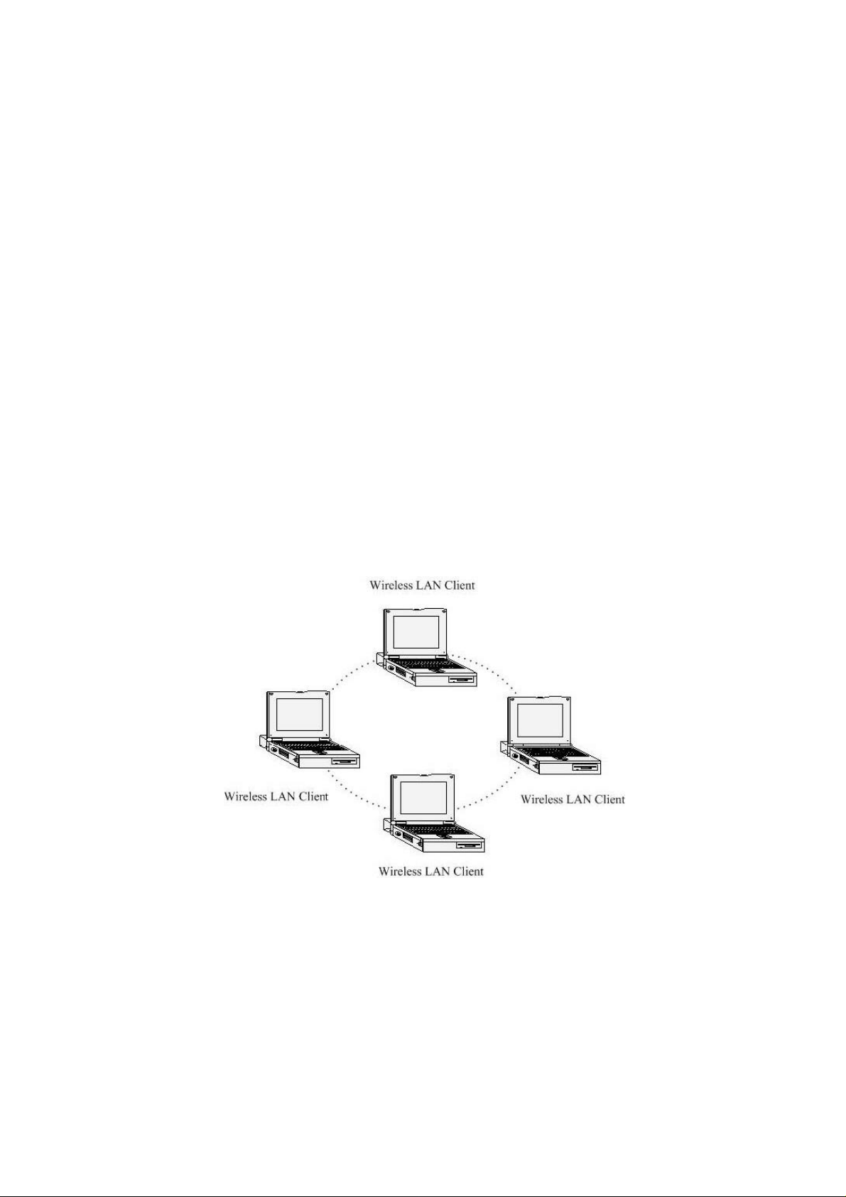
a) Ad-Hoc (peer-to-peer) Mode
This is the simplest network configuration with several computers equipped with
the PC Cards that form a wireless network whenever they are within range of one
another. In ad-hoc mode, each client is peer-to-peer, would only have access to
the resources of the other client and does not require an access point. This is the
easiest and least expensive way for the SOHO to set up a wireless network. The
image below depicts a network in ad-hoc mode.
b) Infrastructure Mode
The infrastructure mode requires the use of an access point (AP). In this mode, all
wireless communication between two computers has to be via the AP. It doesn’t
matter if the AP is stand-alone or wired to an Ethernet network. If used in stand-alone,
the AP can extend the range of independent wireless LANs by acting as a repeater,
which effectively doubles the distance between wireless stations. The image below
Page 6
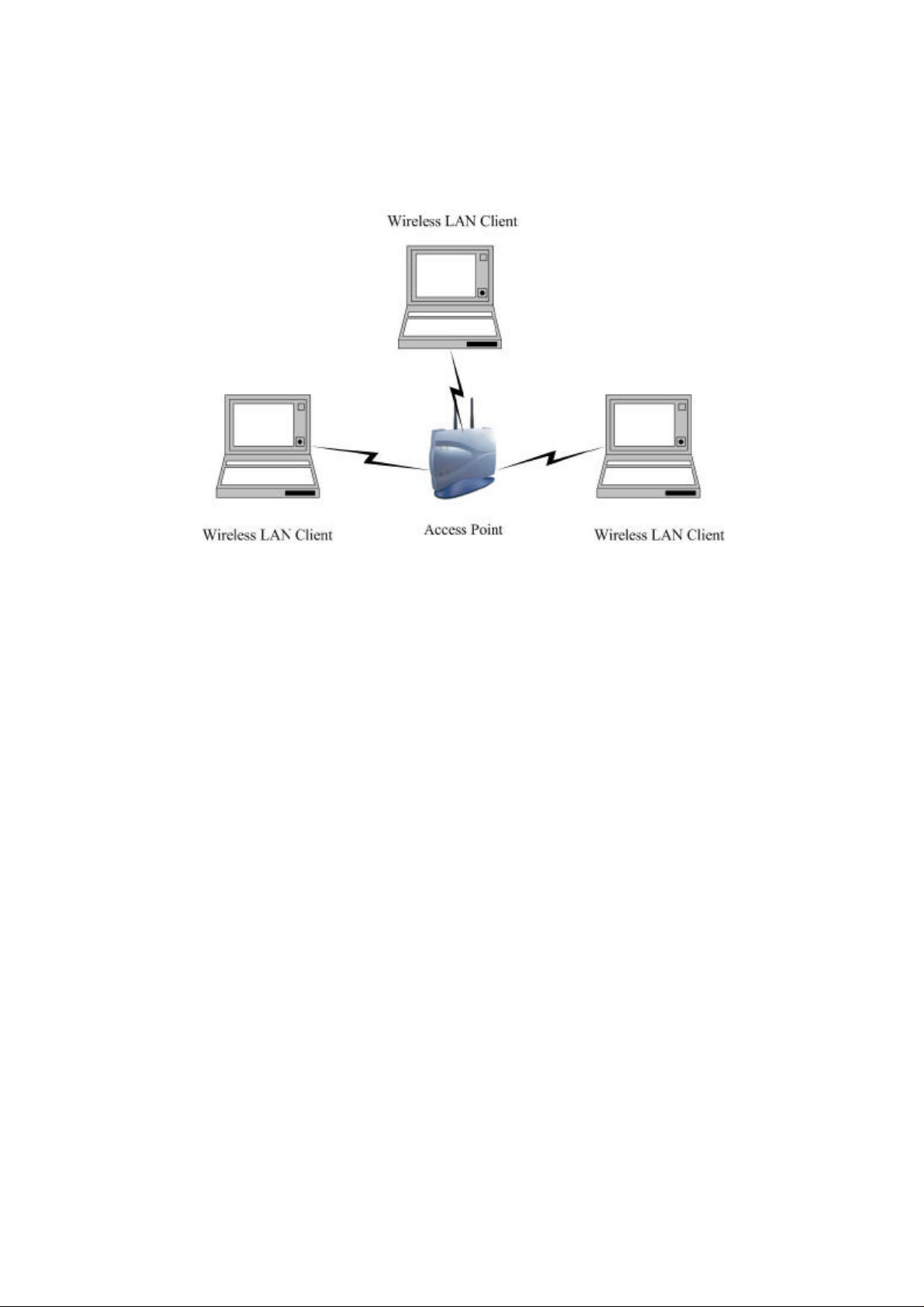
depicts a network in infrastructure mode.
2 Install Drivers & Client Utility
This chapter describes how to install the drivers and client utility in Windows
98/ME/2000/XP.
2.1 Before You Begin
Before installing the new drivers into your PC, you need to remove all of the Wireless LAN
PC card drivers that you have installed.
During the installation, Windows 98SE/ME/2000/XP may need to copy systems files from
its installation CD. Therefore, you may need a copy of the Windows installation CD at
hand before installing the drivers. On many systems, instead of a CD, the necessary
installation files are archived on the hard disk in C:\WINDOWS \OPTIONS\CABS
directory.
2.2 Installing the PC Card Drivers
Follow the steps below in order to install the PC card drivers:
1. Insert the CD-ROM that was provided to you in this package. The setup should run
automatically. If the setup does not run automatically, then you must manually select the
setup.htm file from the CD-ROM drive.
2. Once the setup begins you will see the Install Shield Wizard, as the image depicts
below.
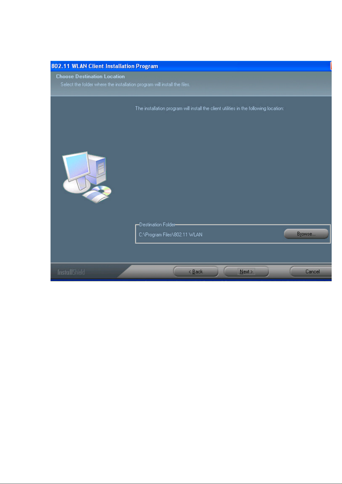
3. Click on the Next button to continue. The Install Wizard will then let you select a
destination folder for the utility and drivers. Click on the Browse button and specify another
Page 7
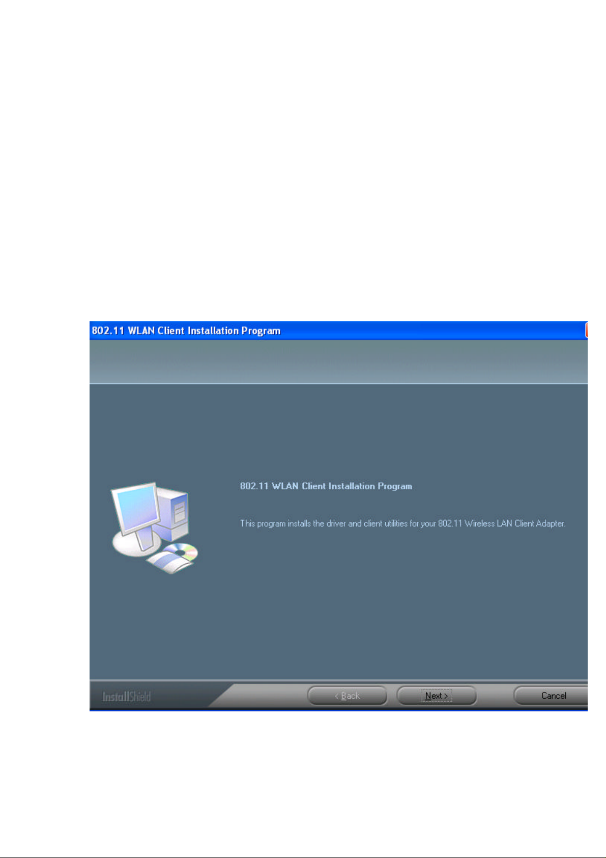
folder, or click on the Next button to use the default folder.
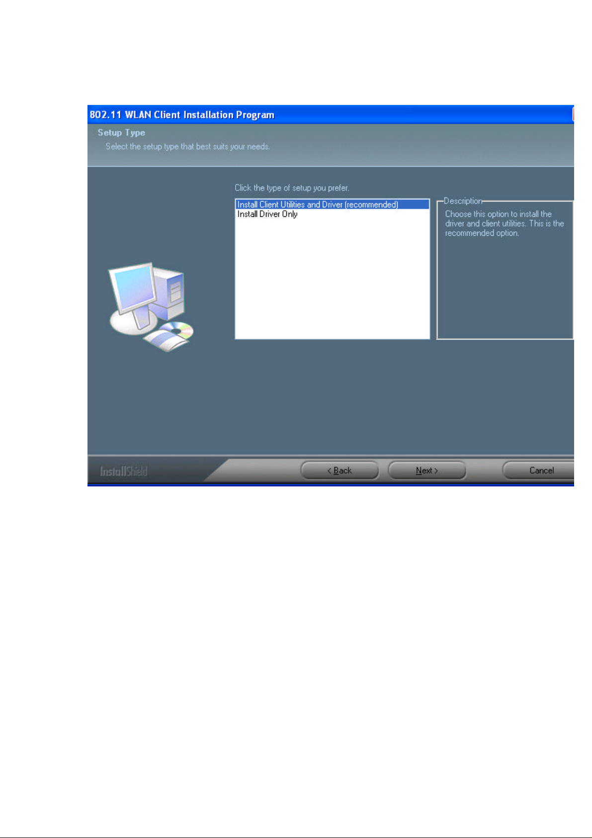
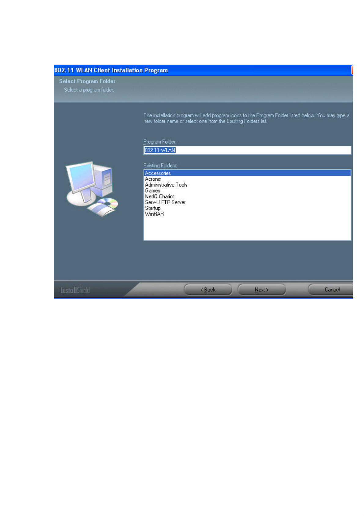
4. The Install Wizard will then allow you to select a Program Folder. Select one from the list,
or click on the Next button to use the default program folder.
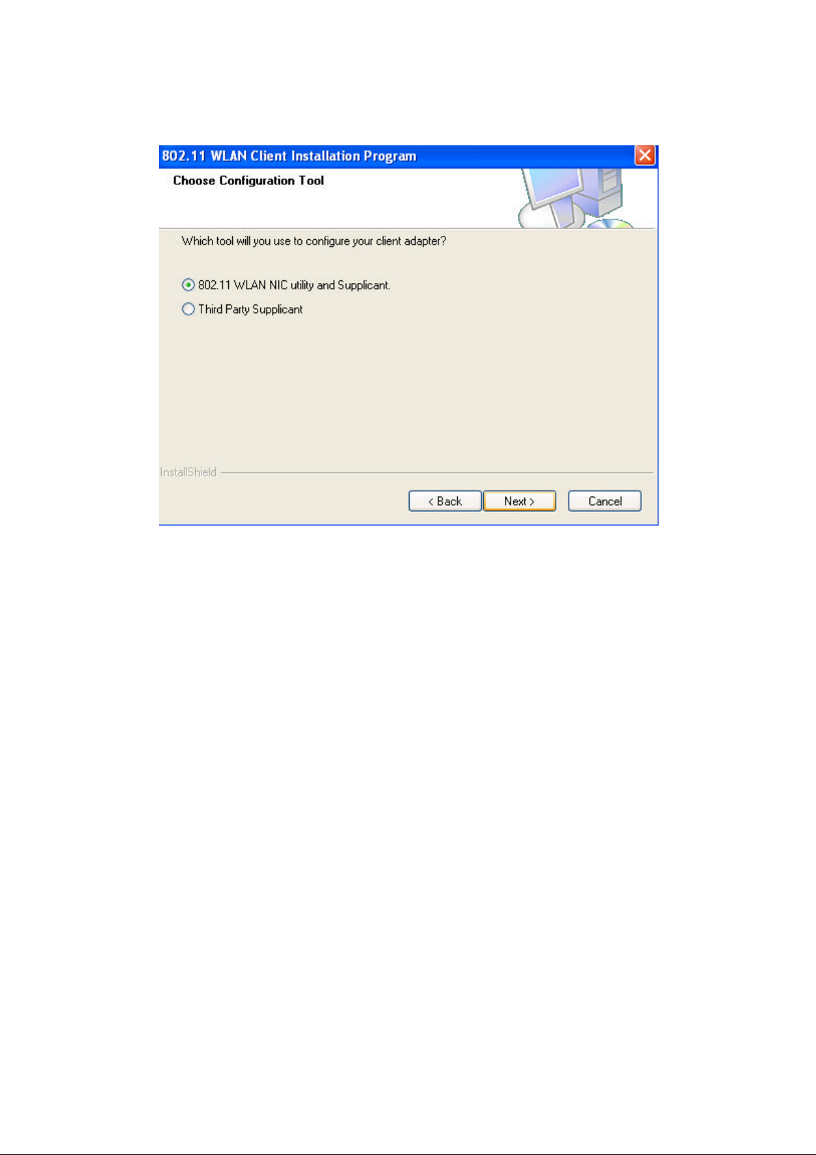
5. The Install Wizard will then inform you that it has enough information to begin the
installation process. Click on the Next button to continue.
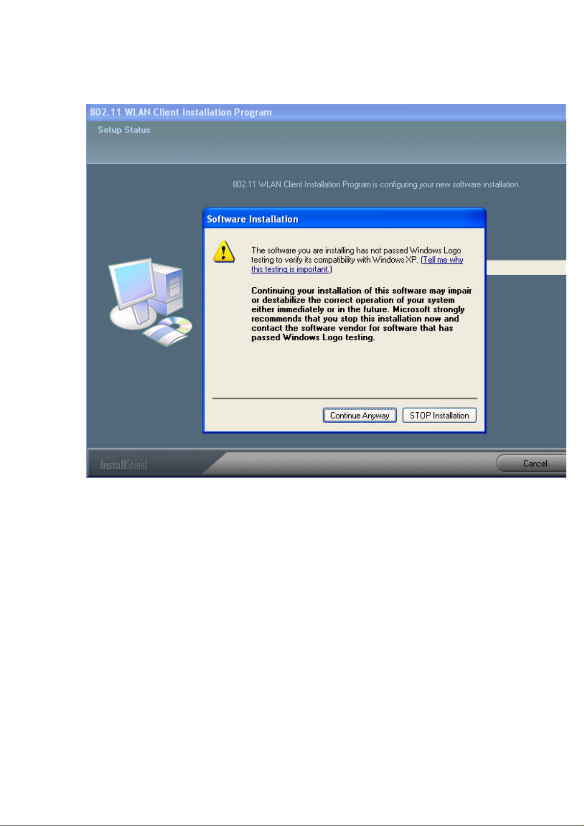
6. The Install Wizard will then begin to copy the files to your computer, as the image
depicts below.
7. Click on the Finish button. The first part of the installation is complete.
8. Gently insert the PC card into the PCMCIA Type II slot of your PC. Windows will
automatically detect the PC card and display the Found New Hardware Wizard, as the
image depicts below.
9. Select the Install the software automatically (Recommended) radio button, and then
click on the Next button to continue. If you are using Windows XP, you will see a message
regarding Windows Logo Testing, click on the Continue Anyway button to continue.
10. The setup will then begin to copy the necessary files. After the copying is completed
you will see the final screen of the installation procedure, as the image depicts below.
Page 8
Page 9
Page 10
Page 11
Page 12
Page 13

Page 14

11. The installation of the PC card is now complete. Click on the Finish button.
3 Using the Client Utility
This chapter describes the features of the PC card and its configuration process. After a
successful installation, an IEEE 802.11 program group will be added to the Programs
menu. To launch the Client Utility click Start > Programs > IEEE 80211 > 802.11 WLAN
NIC Utility. You will then see the Client Utility icon in the system tray of you computer.
Right-click on the Client Utility icon in the system tray and then click on Open Client
Utility, as the image depicts below.
The Client Utility will then appear and display three tabs: Current Status, Profile
Management, and Diagnostics. Each tab is described in detail in the next few sections.
3.1 Current Status
The first tab displayed in the Current Status tab. This tab displays the Profile Name,
Page 15

Network Type, Current Mode, Current Channel, Link Status, Encryption Type, and IP
Address. Configuration for each of these items is described in their respective sections.
3.1.1 Advanced Status
Click on the Advanced button to view more details about the status. You will then see the
following window.
Page 16

The Advanced Status window displays the following: Country, Transmit Power Level,
Network Name (SSID), Power Save Mode, Frequency, Transmit Rate, and
Receive Rate. Configuration for each of these items is described in their respective
sections. Click on the OK button to close this window and return to the Current Status
tab.
3.2 Profile Management
The second tab displayed in the Profile Management tab. This tab is used to create a
new profile, modify and existing profile, remove an existing profile, or activating an existing
profile.
Page 17

3.2.1 Available Networks
Click on the Available Networks… button to select from a list of Access Point and Ad Hoc
networks. You will then see the following window.
Page 18

This window displays a list of Access Point and Ad-Hoc networks in the area. Details
included are the Network Name (SSID), Encryption Key, Signal Strength, Channel, and
Wireless Mode.
If you would like to associate with an Access Point or Ad-Hoc network, select a Network
Name (SSID) from the list and then click on Activate button. You will then be associated
with that network, if you have the correct permissions/keys.
3.2.2 New Profile
Click on the New button in order to create a new network to associate with.
Another window will then appear displaying three tabs: General, Security, and Advanced.
Each tab is described below.
3.2.2.1 General
The first tab displayed is the General tab. Here you can specify a profile name and SSID.
Page 19

a. Profile Name: enter a name for this profile; this can be any name that you may
associate with your network.
b. SSID1: enter the SSID of the network. The SSID is a unique name shared among
all points in your wireless network. The SSID must be identical for all points
in the network, and is case-sensitive.
c. Click on the OK button to save the changes.
3.2.2.2 Security
The second tab displayed is the Security tab. Here you can specify and configure the
security method that is used by your network. There are five types of security methods
available: None, WPA, WPA-PSK, 802.1X, and Pre-Shared Key. Configuration for each
security method is described below.
Page 20

3.2.2.2.1 None
If your network does not use any type of security select the None radio button and then
click on the OK button.
3.2.2.2.2 WPA & 802.1x
WPA (Wi -Fi Protected Access) was designed to improve upon the security features of
WEP (Wired Equivalent Privacy). The technology is designed to work with existing
Wi-FI products that have been enabled with WEP. WPA provides improved data
encryption through the Temporal Integrity Protocol (TKIP), which scrambles the keys
using a hashing algorithm and by adding an integrity-checking feature which makes sure
that keys haven’t been tampered with.
802.1X provides an authentication framework for wireless LANs allowing a user to be
authenticated by a central authority. 802.1X uses an existing protocol called EAP.
If your network uses 802.1X, select that radio button. You must then select an EAP
type from the drop-down list. The three options available are: TLS, TTLS, PEAP
(MS-CHAPv2 & GTC), and LEAP. Each one is described below.
If your network uses WPA, select that radio button. You must then select an EAP
type from the drop-down list. The two options available are: TLS, TTLS, PEAP
(MS-CHAPv2 & GTC), LEAP. Each one is described below.
Page 21

3.2.2.2.2.1 WPA & 802.1x/TLS
EAP (Extensible Authentication Protocol) is an extension to the PPP protocol that
enables a variety of authentication protocols to be used. It passes through the exchange
of authentication messages, allowing the authentication software stored in a server to
interact with its counterpart in the client.
TLS (Transport Layer Security) is an IETF standardized authentication protocol that uses
PKI (Public Key Infrastructure) certificate-based authentication of both the client and
authentication server.
Select TLS from the drop-down list, and then click on the Configure button. The Client
Utility will then search your computer for any certificates. If you do not have any
certificates, you will see the following message, requiring you to select another EAP
option. Click on the OK button.
Page 22

To enable EAP-TTLS security:
1. To use EAP-TTLS security, the machine must already have the EAP-TTLS certificates
downloaded onto it. Check with the IT manager. EAP security uses a dynamic
session-based WEP key from the USB device and RADIUS server for encryption, and a
client certificate for authentication.
2. If EAP-TTLS is supported, choose EAP-TTLS from the drop-down menu on the right,
and then click the Configure button.
Page 23

3.2.2.2.2.2 WPA & 802.1x – PEAP
EAP (Extensible Authentication Protocol) is an extension to the PPP protocol that
enables a variety of authentication protocols to be used. It passes through the exchange
of authentication messages, allowing the authentication software stored in a server to
interact with its counterpart in the client.
PEAP (Protected Extensible Authentication Protocol) is a protocol developed jointly by
Microsoft, RSA Security, and Cisco for transmitting authentication data, including
passwords over a 802.11 wireless network. PEAP authenticates wireless LAN clients
using only server-side digital certificates by creating an SSL/TLS tunnel between the
client and the authentication server. The tunnel then protects the subsequent user
authentication exchange.
To enable PEAP (EAP-MSCHAP V2) security:
1. To use PEAP (EAP-MSCHAP V2) security, the server must have PEAP certificates,
and the server properties must already be set. Check with the IT manager.
2. If supported, choose PEAP (EAP-MSCHAP V2) from the drop-down menu on the right,
then click the Configure button.
Page 24

To enable PEAP (EAP-GTC) security:
1. To use PEAP (EAP-GTC) security, the server must have PEAP certificates, and the
server properties must already be set. Check with the IT manager.
2. If PEAP is supported, choose PEAP from the drop-down menu on the right, and then
click the Configure button.
To enable WPA & 802.1x_LEAP security:
1. LEAP security requires that all infrastructure devices are configured for
LEAP authentication. Check with the IT manager.
Page 25

2. If supported, choose LEAP from the drop-down menu on the right, then click the
Configure button.
3.2.2.2.3 WPA – PSK
WPA – PSK (Pre-shared Key) is used in a Pre Shared Key mode that does not require an
authentication server. Access to the Internet and the rest of the wireless network
services is allowed only if the pre-shared key of the computer matches that of the Access
Point. This approach offers the simplicity of the WEP key, but uses stronger TKIP
encryption.
If your network uses WPA-PSK, select that radio button, and then click on the Configure
button. You will then see the following window.
Page 26

Enter the WPA pass-phrase in the text box. The pass-phrase must be a minimum of 8
characters. This is the password shared between the Access Points and the Clients. Click
on the OK button when completed.
3.2.2.2.5 Pre-Shared Key
Pre-shared Key does not require an authentication server. Access to the Internet and
the rest of the wireless network services is allowed only if the pre-shared key of the
computer matches that of the Access Point. This approach offers the simplicity of the
WEP key, but uses stronger TKIP encryption.
To enable Pre-Shared Key security:
1. Click on the Security tab, and choose the Pre-Shared Key radio button. Click the
Configure button.
2. Define the pre-shared keys and select the default key.
3. Click OK.
4. If the access point that the Cardbus Adapter is associating to have WEP set to
Optional and the client has WEP enabled, make sure that Allow Association to Mixed
Cells is checked on the Security Tab to allow association.
5. Click OK and enable the profile.
Page 27

3.2.2.3 Advanced
The third tab displayed is the Advanced tab. Here you can configure details about an
Access Point or Ad Hoc network Configuration for each security method is described
below.
3.2.2.3.1 Access Point
Page 28

Power Save Mode: select a power save mode from the drop-down list.
Network Type: select Access Point from the drop-down list.
802.11b Preamble: select Short & Long or Long Only.
Transmit Power Level: select a power level from the drop-down list.
Wireless Mode 2.4 GHz 11 Mbps: place a check in this box if you would like to use
2.4GHz 11 Mbps.
Wireless Mode: place a check in this box if you would like to use the available
frequencies. Click on the OK button to continue.
3.2.2.3.2 Ad Hoc
Network Type: select Ad Hoc from the drop-down list.
802.11b Preamble: select Short & Long or Long Only.
Transmit Power Level: select a power level from the drop-down list.
Wireless Mode 2.4 GHz 11 Mbps: place a check in this box if you would like to use
2.4GHz 11 Mbps.
Wireless Mode: place a check in this box if you would like to use the available
frequencies.
Channel: select a channel number from the drop-down list, or set the channel to
auto. Click on the OK button to continue.
3.3 Diagnostics
The third tab displayed in the Diagnostics tab. This tab displays transmit and receive
frame details.
Page 29

3.3.1 Advanced Statistics Click on the Advanced Statistics button to view more
detailed statistics.
Page 30

3.3.2 Driver Information
Click on the Driver Information button to view details about the driver. Included
information is: Card Name, MAC Address, Driver, Driver Version, and Driver
Date.
Page 31

4. Un-installation
If the PC card installation is unsuccessful for any reason, the best way to solve the
problem may be to completely uninstall the PC card and its software and repeat the
installation procedure again.
Follow the steps below in order to uninstall the Client Utility:
1. Click on Start > Settings > Control Panel.
2. Double click on the System icon.
3. Click on the Hardware tab, and then click on the Device Manger button.
4. Select Network adapters to view a list of network adapters on your PC.
5. Right-click on the WLAN Wireless Network Adapter, you will then see a window
similar to the image below.
6. Select Uninstall. You will then see the following message asking you to confirm the
device removal.
7. Click on the OK button. The driver Uninstallation will then complete.
8. Click Start > Programs > WLAN Wireless Network Adapter, you will then see the
following window.
9. Select the Remove radio button, and then click on the Next button.
10. A message will then appear asking to you confirm the Uninstallation. Click on the OK
button.
11. The Client Utility will then begin to uninstall. Another window will then appear select
Yes, I want to restart my computer now radio button, and then click on the Finish
button. The Un-installation process is complete.
Page 32

Page 33

Page 34

Appendix A - Specifications
Page 35

1. General
Radio Data Rate
(Auto-rate capable)
Network Standards WECA (Wi-Fi & Wi-Fi5 Compliant),
Security IEEE802.11x Support for LEAP (Optional)
Network Architecture Support ad-hoc, peer-to-peer networks and
Drivers Windows 98/ME/2000/XP
Access Protocol CSMA/CA with ACK
Roaming IEEE802.11b compliant
Operating Voltage 3.3V/5V
Regulation
Certifications
LED Indicator RF Link activity
2. RF Information
Frequency Band 802.11b/g :
Modulation
Technology
Receive Sensitivity
(Typical)
Transmit Output Power 802.11b/g : Up to 21dBm
3. Environmental
802.11g :
6, 9, 12, 18, 24, 36, 48 & 54Mbps
802.11b :
1, 2, 5.5, 11Mbps
IEEE802.11, IEEE802.11g draft, IEEE802.11b,
draft IEEE802.11e, f, h and I standards,
IEEE802.11x (Optional)
WPA – Wi-Fi Protected Access (64, 128,
152-WEP with TKIP)
infrastructure
communications to wired Ethernet networks via
Access Point
FCC Part 15/UL, ETSI 300/328/CE
2.412 to 2.462GHz
802.11g : OFDM (64-QAM, 16-QAM, QPSK,
BPSK)
802.11b : DSSS (DBSK, DQPSK, CCK)
802.11b/g :
-91dBm@1Mbps, -85dBm@9Mbps, -77dBM@
36Mbps
-89dBm@2Mbps, -82dBm@12Mbps, -76dBM@
48Mbps
-87dBm@5.5Mbps, -80dBm@18Mbps,
-73dBM@ 54Mbps
-86dBm@6Mbps, -78dBm@24Mbps
Page 36

Temperature Range
-10℃ to 55℃ – Operating
-40℃ to 70℃ – Storage
Humidity
5% to 95% Typical
(non-condensing)
4. Physical Specifications
Interface 32-bit CardBus PC Card Standard V7.1 Type II
Antenna Integrated built-in diversity Antenna
Dimensions 118(L)mm * 54(W)mm * 6.3(H)mm (4.65in *
2.13in * 0.30in)
Appendix B – FCC Interference Statement
This equipment has been tested and found to comply with the limits for a Class B digital
device, pursuant to Part 15 of the FCC Rules. These limits are designed to provide
reasonable protection against harmful interference in a residential installation. This
equipment generates uses and can radiate radio frequency energy and, if not installed
and used in accordance with the instructions, may cause harmful interference to radio
communications. However, there is no guarantee that interference will not occur in a
particular installation. If this equipment does cause harmful interference to radio or
television reception, which can be determined by turning the equipment off and on, the
user is encouraged to try to correct the interference by one of the following measures:
. • Reorient or relocate the receiving antenna.
. • Increase the separation between the equipment and receiver.
. • Connect the equipment into an outlet on a circuit different from that to which the
receiver is connected.
. • Consult the dealer or an experienced radio/TV technician for help.
FCC Caution: Any changes or modifications not expressly approved by the party
responsible for compliance could void the user's authority to operate this equipment.
This device complies with Part 15 of the FCC Rules. Operation is subject to the following
two conditions:
1. This device may not cause harmful interference
2. This device must accept any interference received, including interference that may
cause undesired operation.
IMPORTANT NOTE:
FCC Radiation Exposure Statement:
This equipment complies with FCC radiation exposure limits set forth for an
uncontrolled environment.
This device complies with FCC RF Exposure limits set forth for an uncontrolled
environment, under 47 CFR 2.1093 paragraph (d) (2).
Page 37

This transmitter must not be co-located or operating in conjunction with any other
antenna or transmitter.
CH1~CH11 for 2.4GHz by specified firmware controlled in U.S.A.
Highest SAR test Value: 1.280 W / kg
this device is only approved for laptop configurations utilizing side mounted PCMCIA Card slots.
 Loading...