


SENAO
High-Speed Wireless 11g Access Point
User’s Manual
Version: 1.0

High-Speed Wireles s Access Poi n t Versio n 1.0
Table of Contents
1 INTRODUCTION.....................................................................................................4
1.1 F
1.2 P
EATURES
ACKAGE CONTENTS
& B
ENEFITS
........................................................................................ 4
............................................................................................4
2 UNDERSTANDING THE HARDWARE................................................................5
2.1 H
2.2 H
ARDWARE CONFIGURATION
ARDWARE INSTALLA TION
...............................................................................5
...................................................................................5
3 PC CONFIGURATION.................................................................. ..........................5
3.1 TCP/IP C
3.2 W
IRELESS
ONFIGURATION
LAN C
ONFIGURATION
...................................................................................... 5
........................................................................ 7
4 WEB CONFIGURATION........................................................................................8
4.1 L
4.2 G
4.3 S
OGGING IN
ETTING FAMILIAR WITH THE
YSTEM
......................................................................................................... 8
GUI ......................................................................8
................................................................................................................9
4.3.1 Administrator Settings.................................................................................9
4.3.2 Firmware Upgrade........... ... ......................................................................10
4.3.3 Configuration Tools...................................................................................10
4.3.4 Factory Defaults........................................................................................ 1 1
4.4 LAN...................................................................................................................12
4.5 W
IRELESS
........................................................................................................... 12
4.5.1 General...................................................................................................... 12
4.5.2 802.11g......................................................................................................13
4.5.2.1
4.5.2.2
4.5.2.3
4.6 S
TATISTICS
Security Setting
Security Server Settings
ACL Settings
......................................................................................................... 17
...............................................................................15
................................................................16
...................................................................................17
4.6.1 2.4 GHz Statistics......................................................................................18
APPENDIX A – SPECIFICATIONS........... ....................... ...................................... .....19
Page 2 of 20

High-Speed Wireles s Access Poi n t Versio n 1.0
Revision History
Version Date Notes
1.0 September 17, 2003 Initial Version
Page 3 of 20

High-Speed Wireles s Access Poi n t Versio n 1.0
1 Introduction
This chapter describes the features & benefits, package contents, applications, and
network configuration.
1.1 Features & Benefits
Features Benefits
High Speed Data Rate Up to 108Mbps/ Super
G Mode
Fully IEEE 802.11g draft standards compliant,
and backwards compatible with IEEE802.11b
products
Transmission Power Control (TPC) support Offers flexibility to adjust RF output power.
Dynamic Frequency Selection (DFS) support Provides flexible selection of the best
Multi country Roaming (802.11d) Automatically adjusts regulatory domain to
Wi-Fi Protected Access Enhances authentication and security.
64 /128/152-bit WEP data encryption Powerful data security.
MAC address filtering Ensures secure network connections
Remote Configuration via Web-
browser/Telnet
Firmware upgrade through Web-browser Easy firmware upgrade reduces operations
Capable of handling heavy data payloads
such as MPEG video streaming.
Interoperable with existing 2.4GHz device
and networks
frequency to allow mobility among all
existing IEEE802.11b/g networks.
operate in different countries.
Easy to configure or manage the device
remotely.
overhead.
1.2 Package Contents
h
One Access Point
h
One Power Adapter
h
One CAT 5 UTP Cable
h
One Fast Start Guide
h
One CD-ROM with User’s Manual Included
Page 4 of 20

High-Speed Wireles s Access Poi n t Versio n 1.0
2 Understanding the Hardware
2.1 Hardware Configuration
h
RJ-45 Ethernet Connector –
Ethernet LAN.
h
Reset Butt on – By holding this down for more than five seconds, the AP will
reset to its factory default settings.
h
Power Supply Connector –
Provides 10/100 Mbps connectivity to a wired
Connects to the power adapter.
2.2 Hardware Installation
A. Configure your notebook or PC with a wireless LAN card.
B. For a wired LAN , connect your PC’s Ether net port to the AP’s LAN port v ia an
Ethernet cable.
C. For WLAN, position the Access Point in a proper position.
D. Plug in the power cord into the power outlet.
3 PC Configuration
3.1 TCP/IP Configuration
Follow the steps below in order to configure the TCP/IP settings of your PC.
A. In th e Control Panel dou ble click
on the connection of your Network Interface Card (NIC). You will then see the
following screen.
Network Connections
, and then double click
Page 5 of 20

High-Speed Wireles s Access Poi n t Versio n 1.0
B. Select
Internet Protocol (TCP/IP)
and then click on the
Properties
button. Th is
will allow you to configure the IP address of your PC. You will then see the
following screen.
Page 6 of 20

High-Speed Wireles s Access Poi n t Versio n 1.0
C. Select
Use the follow ing IP addres s
radio button, and then enter an IP address
and subnet m ask for your PC. Make sur e that t he Access P oint and your PC are
on the same subnet. The default IP address and subnet mask of the Access
Point are
192.168.1.1
255.255.255.0
and
respectively.
D. Click on the OK button, your PC’s TCP/IP settings have been configured.
3.2 Wireless LAN Configuration
Follow the steps below in order to configure the Wireless LAN settings.
A. Launch the
WLAN Client Utility
and click on the
Configuration
tab.
Profile Name
B.
Network Name
C.
Network Type
D.
Power Save Mode
E.
Transmit Rate
F.
: enter a name for this profile.
: enter the SSID. (Default name: Any)
: select
: select
Access Point
: Select
Off
or On from t h e dr o p- d own l i s t .
Fully Automatic
from t h e dr o p - d own l i s t .
from t h e dr o p - d own l i s t .
G. Click on the OK button.
Page 7 of 20

High-Speed Wireles s Access Poi n t Versio n 1.0
4 Web Configuration
4.1 Logging In
h
To config ur e t h e A cce s s Poi n t t hr o ug h t h e web- b r owse r , enter th e IP ad dress of the
Access Point (default: 192.168.1.1) into the address bar of the web-browser, and
Enter
press
h
You will then see the login window. Enter
the Password and then click on the OK button.
h
You can also change the username and password under the
Settings
username and password.
h
4.2 Getting Familiar with the GUI
.
option. Refer to section
admin
as the User name and
4.3.1 Administrator Settings
iktpw
Administrator
to change the
as
h
After logging in, the first page that is displayed in the
h
The GUI consists of three parts and is displayed in the image below:
Navigation Bar
A.
Main Page
B.
Top Right-hand Corner
C.
Home
click on the
button to return to the status page. Click on the
: used to navigate through the available options.
: used to view and configure the AP’s settings.
: quick b utt ons for
Reset
button to restart the AP.
Home, Exit
Status
, and
Exit
page.
Reset
. Click on the
button to logout, and
Page 8 of 20

High-Speed Wireles s Access Poi n t Versio n 1.0
C
A
4.3 System
h
Click on the
Administrator Settings, Firmware Upgrade, Configuration Tools, Factory Default,
and Rest. Each one is described in detail below.
System
link on the navigation bar, you will then see five options:
4.3.1 Administrator Setting s
h
Click on the
name, password, system name and telnet.
h
Set anot her user name and p assword to rest rict m anagem ent ac cess to th e Acc ess
Point.
Administrator Settings
h
Username:
h
Password:
h
System Name:
h
Enable Telnet:
this device.
enter a new user name.
enter a new password.
enter a uni q u e na me for th is devic e .
place a check in this box if you would like to allow telnet access to
B
link. On th is page you ca n config ure the user
Page 9 of 20
High-Speed Wireles s Access Poi n t Versio n 1.0
h
Click on the
Apply
button to confirm and save the changes.
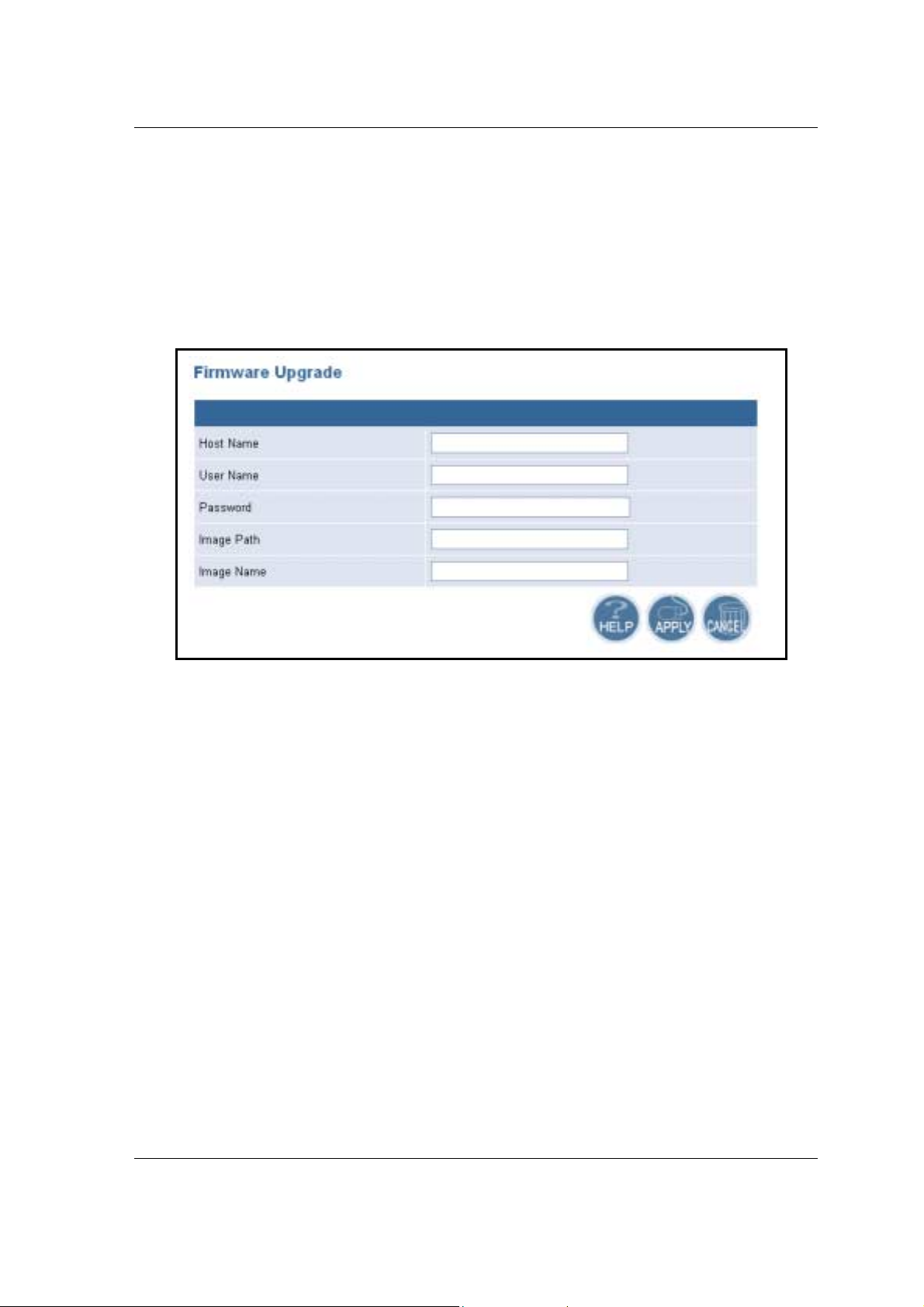
4.3.2 Firmw are Upgrade
h
Click on the
the AP.
h Host Name:
h User Name:
Password:
h
h Image Path:
h Image Name:
h
Click on the
Firmware Upgrade
enter the host name or host IP address.
enter the user name for the host.
enter th e pa s sword for th e ho s t .
enter the path of the image file.
enter the name of the image file.
Apply
button to confirm and save the changes.
link. Th i s page is u se d t o u pg r ade the firm war e o n
4.3.3 Configuration Tools
h
Click on the
Configuration Script
application.
Configuration Tools
link on the navi gation bar, you wi ll then see the
page. This page allows you to develop a script for an
Page 10 of 20

High-Speed Wireles s Access Poi n t Versio n 1.0
h Host Name:
h User Name:
h Password:
h Script Path:
h Script Name:
h
Click on the
enter the host name for the script resides.
enter the user name of the host.
enter th e pa s sword of the ho s t .
enter the path of the script file.
enter the name of the script file.
Apply
button to confirm and save the changes.
4.3.4 Factory Defaults
h
Click on the
original factory settings.
Restore
button of the Access Point to perform a reset and restore the
Page 11 of 20
High-Speed Wireles s Access Poi n t Versio n 1.0
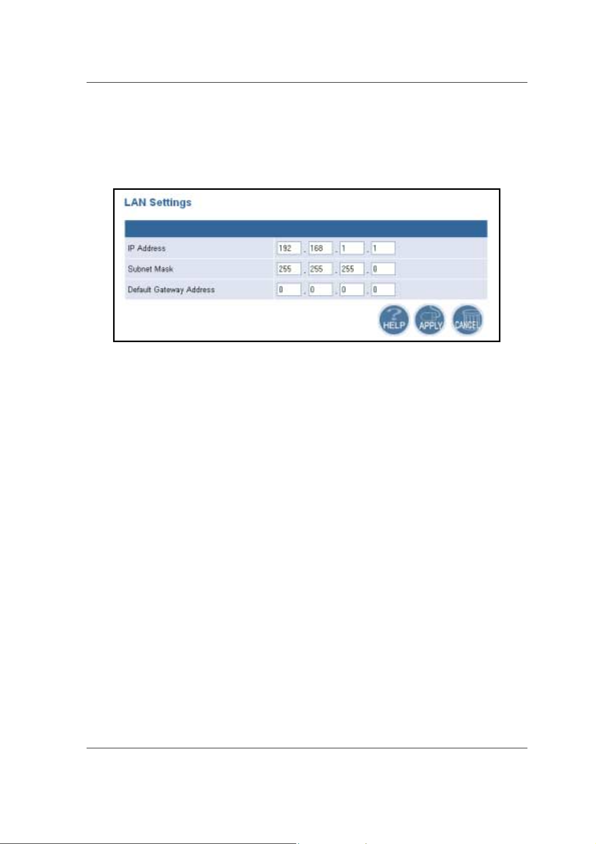
4.4 LAN
h
Click on the
will then see the LAN Settings page. On this page you can configure the LAN IP,
subnet mask, and default gateway IP addresses.
h
IP Address:
h
Subnet Mask:
h
Default Gateway Address:
h
Click on the
4.5 Wireless
LAN
link on the na vigation bar, and then click o n
enter the IP address of the Access Point.
enter a subnet mask for the IP address.
enter a gateway IP for the Access Point.
Apply
button to confirm and save the changes.
LAN Settings.
You
h
Click on the
General and 80211g. Each one is described in detail below.
Wireless
link on the navigation bar, you will then see two options:
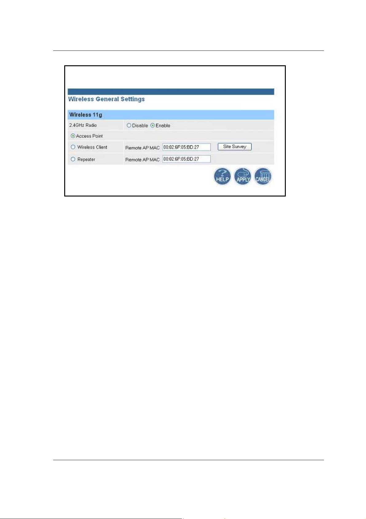
4.5.1 General
h
Click on the
Access Point, and choose to enable or disable the 2.4GHz radio.
General
link on the navigation bar. On this page you can select for the
Page 12 of 20
High-Speed Wireles s Access Poi n t Versio n 1.0
h 2.4 GHz Radio
h
Select a radio button for the type of device you would like this to be. Options
available are:
Point
, you are not required to enter any additional information. If you select
Wireless Client
Point. If you select
Access Point. If you do not know the MAC address of the Access Point, click on
Site Survey
the
h
Click on the
: select
Access Point, Wireless Client
, you are req uired to en ter the MAC a ddress of t he remote Ac cess
button to view and select one from the list.
Apply
Disable
Repeater
button to confirm and save the changes.
Enable
or
, you are requi red to enter the MAC addr ess of the
for the 2.4GHz radi o .
Repeater
, and
. If you select
Access
4.5.2 802.11g
h
Click on the
802.11g settings.
802.11g
link on the n avigation ba r. On t hi s pag e you can configure the
Page 13 of 20

High-Speed Wireles s Access Poi n t Versio n 1.0
h SSID:
enter the SSID of the wireless network. The SSID is a unique name shared
among all points in your wireless network. The SSID must be identical for all points
in the network, and is case-sensitive.
h Suppre ss SSID:
place a check in this box if you would like the SSID to be hidden
from other Access Points or a site survey.
h Wireless Mode:
select a data rate from the drop-down menu. One option is
11Mbps and the other is 54Mbps.
h Security:
place a check is this box if you would like to use
like to c onf igure a mor e det a iled security, click on the
WPA
only. If you would
Edit Securi ty Setting
button.
This option is described in the next section.
h Data Rate:
select a data rate from the drop-down list; by default
h Transmit Power:
select a transmit power from the drop-down list; by default
Best
is selected.
full
selected.
h Antenna Diversity:
select
h Beacon Interval (20-1000):
Best, 1
or 2 from the drop-down list.
enter a value between 20 and 1000 for the beacon
interval. Beacons announce the existence for the 802.11 networks at regular
intervals.
h Data Beacon Rate DTIM (1-16384):
enter the data b eacon rat e; the defa ult rat e is
1.
h Fragment Length (256-2346):
enter a value between 256 and 2346 for the
is
Page 14 of 20

High-Speed Wireles s Access Poi n t Versio n 1.0
fragment length.
h RTS/CTS Threshold (256-2346):
RTS/CTS threshold. Any packet in the RTS/CTS handshake larger than the
specified size will be discarded.
h Short Preamble:
Enable
selected only long preambles are used.
h Allow 2.4G Hz 54Mbps Stations Only:
the association of 2.4GHz Mbps station only.
h
Click on the
is selected, both short and long preambles are used. When
Apply
use this radio button to specify short preamble usage. When
button to confirm and save the changes.
enter a value between 256 and 2346 for the
Disable
use this radio button to Enable or Disable
4.5.2.1 Security Setting
h Security Mode:
shared Key
h Key Entry Method:
Hexadecimal
h Default Shared Key:
Encryption Key
128-bit
152-bit.
or
select a security mode; options available are
Dynamic.
, or
Ascii Text.
or
select a default-shared key, and then enter the key in the
text box. From the
select a type of key method; options available are
Key Length
drop down list, select
Disabled, Pre-
none, 64-bit
is
,
Page 15 of 20
High-Speed Wireles s Access Poi n t Versio n 1.0
h Access Control List:
click on the
Edit ACL Settings
select Enable or Disable for MAC access control lists. Then
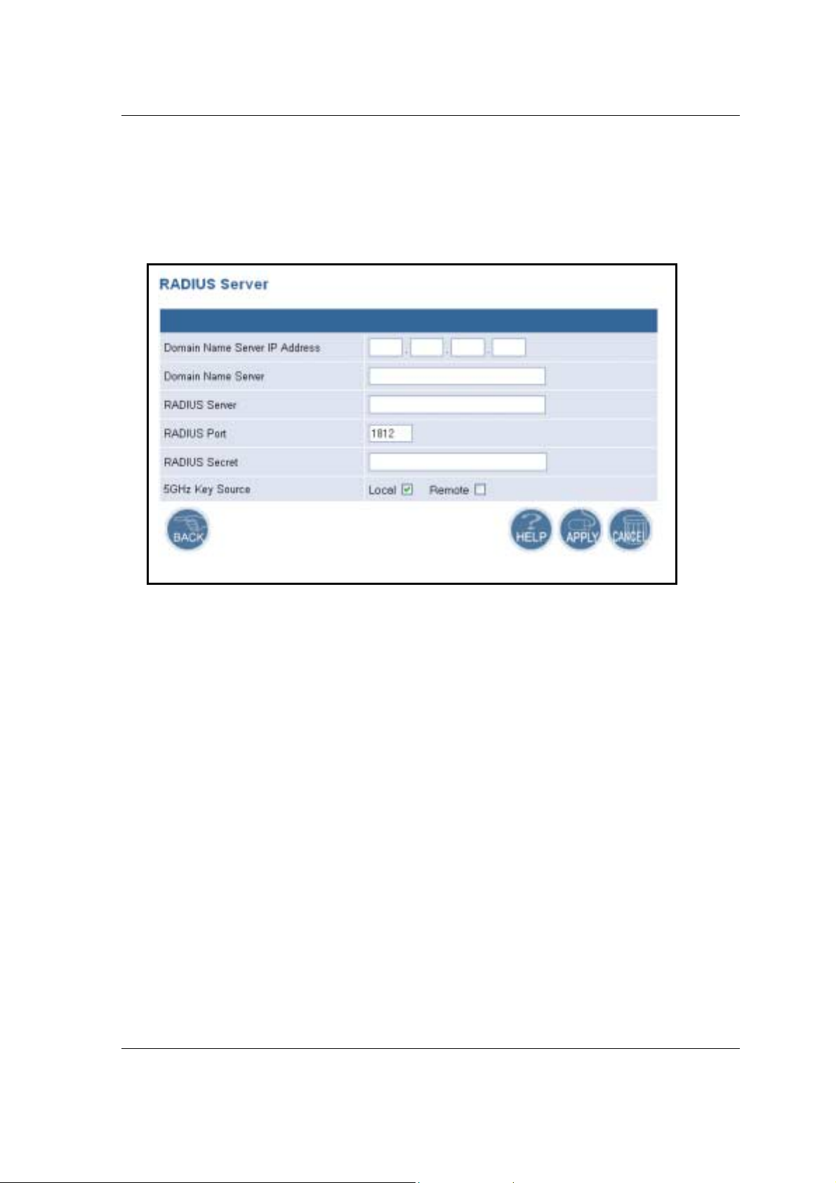
4.5.2.2 Security Server Settings
h Domain Name Server IP address:
server.
h Domain Name Server:
h RADIUS Server:
h RADIUS Port:
h RADIUS Secret:
h 5GHz Key Source:
RADIUS key is located in the AP.
located in the RADIUS server.
h
Click on the
enter the name of the domain name server.
enter the IP address of the RADIUS server.
enter the port of the RADIUS server.
enter th e pa s sword of the R A D IUS serv e r .
select a l ocation of the RADIUS k ey.
Apply
button to confirm and save the changes.
button.
enter the IP address of the domain name
Local
specifie s that the
Remote
specifies that the RADIUS key is
Page 16 of 20
High-Speed Wireles s Access Poi n t Versio n 1.0
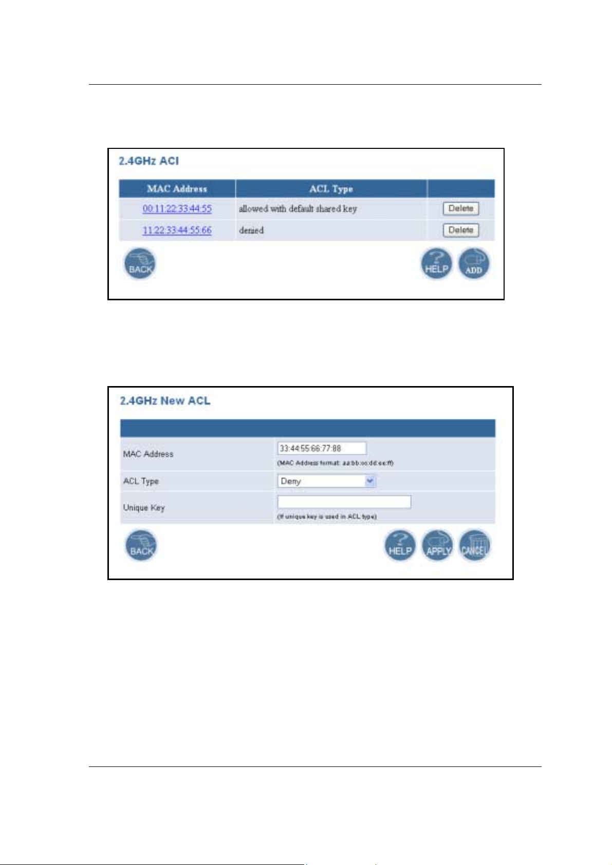
4.5.2.3 ACL Settings
h
To delete an existing MAC ACL, click on the
h
Click on the
Add
button to add another MAC ACL.
Delete
button.
Add New ACL
h
MAC Address
h
ACL Type
Deny, Default Shared Key, 64-bit, 128-bit or 152-bit.
h
Unique Key:
h
Click on the
: enter the MAC address.
: select an ACL type from the drop-down list. Options available are
this is only required if a unique key is used in the ACL type.
Apply
button to confirm and save the changes.
Allow,
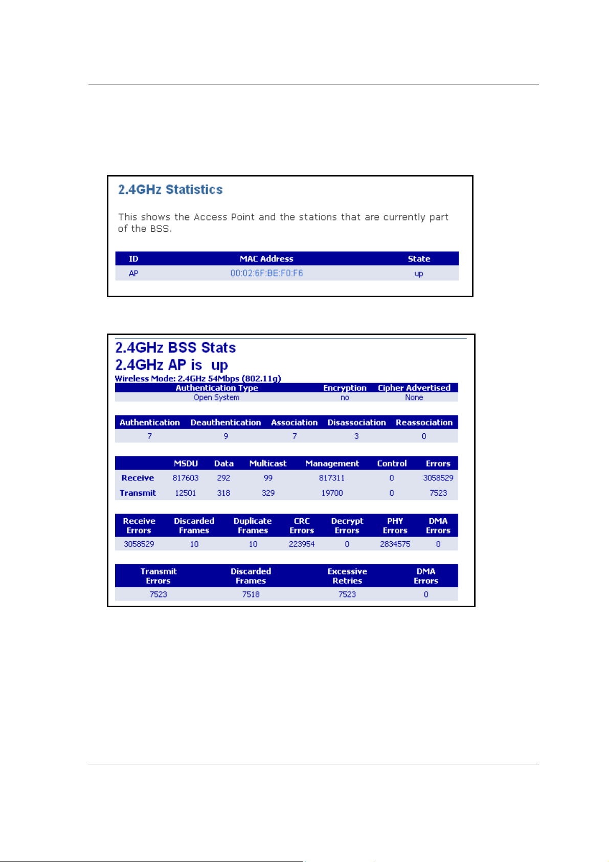
4.6 Statistics
h
Click on the
Statistics options.
Statistics
link on the navigation bar, you will then see the 2.4GHz
Page 17 of 20
High-Speed Wireles s Access Poi n t Versio n 1.0
4.6.1 2.4 GHz Statistics
h
Click on the
stations that are currently part of the BSS.
h
Click on the MAC address to view detailed statistics.
2.4GHz Stat istics
link on the navi gati on bar . You will then see a list of
Page 18 of 20

High-Speed Wireles s Access Poi n t Versio n 1.0
Appendix A – Specifications
General
Data Rates
Media Access Protocol
Standards
Power Requirements
802.11g :
802.11b :
Carrier sense multiple access with collision avoidance (CSMA/CA)
IEEE802.11g draft, IEEE802.11d, IEEE802.1x, IEEE802.11h,
IEEE802.3, IEEE802.3u
12 V/ 1A
6, 9, 12, 18, 24, 36, 48, 54Mbps
1, 2, 5.5, 11Mbps
Compliance
Security
Management
Firmware Upgrade
RF Information
Frequency Band
Modulation Technology 802.11g :
Operating Channels
Receive Sensitivity
Transmit Output Power
(Typical)
Physical
FCC Part 15/UL, ETSI 300/328/CE
y WEP (64, 128, 152bit)
y Wi-Fi Protected Access(64,128,152-WEP with TKIP, Shared
Key Authentication)
Web-based configuration (HTTP), Telnet
Upgrade firmware via TFTP/Web browser
2.412~2.462GHz(US)
2.412~2.484GHz(Japan)
2.412~2.472GHz(Europe ETSI)
2.457~2.462GHz(Spain)
2.457~2.472GHz(France)
802.11b :
11 for North America, 14 for Japan, 13 for Europe,
2 for Spain, 4 for France
-91dBm @ 1Mbps -84dBm @ 6Mbps -75dBm @ 24Mbps
-90dBm @ 2Mbps -82dBm @ 9Mbps -73dBm @ 36Mbps
-89dBm @ 5.5Mbps -79dBm @ 12Mbps -70dBm @ 48Mbps
-87dBm @ 11Mbps -77dBm @ 18Mbps -68dBm @ 54Mbps
802.11g :
802.11b :
OFDM (64-QAM, 16-QAM, QPSK, BPSK)
DSSS (DBPSK, DQPSK, CCK)
Up to 20dBm(USA) ; Up to 20dBm(Europe ETSI)
Up to 20dBm(USA) ; Up to 20dBm(Europe ETSI)
Interface
Status LEDs
Antenna
Dimensions
Environmental
Temperature Range
Humidity (non-ondensing)
1* 10/100Base Ethernet LAN Port
Power, LAN, WLAN
One non-detachable diversi ty antenna
135(L)mm x 110(W)mm x 31(H)mm
0°C to 55°C (32°F to 131°F) – Operating
-40°Cto 70°C(-40°F to 158°F) – Storage
5%~95% Ty pical
Page 19 of 20

High-Speed Wireles s Access Poi n t Versio n 1.0
Federal Communication Commission Interference Statement
This equipment has been tested and found to comply with the limits for a
Class B digital device, pursuant to Part 15 of the FCC Rules. These limits are
designed to provide reasonable protection against harmful interference in a
residential installation. This equipment generates, uses and can radiate radio
frequency energy and, if not installed and used in accordance with the
instructions, may cause harmful interference to radio communications.
However, there is no guarantee that i nterference will not occur in a particular
installation. If this equipment does cause harmful interference to radio or
television reception, which can be determined by turning the equipment off
and on, the user is encouraged to try to correct the i nterference by one of the
following measures:
- Reorient or relocate the receiving antenna.
- Increase the separation between the equipment and receiver.
- Connect the equipment into an outlet on a circuit different from that
to which the receiver is connected.
- Consult the dealer or an experienced radio/TV technician for help.
This device complies with Part 15 of the FCC Rules. Operation is subject to
the following two conditions: (1) This device may not cause harmful
interference, and (2) this device must accept any interference received,
including interference that may cause undesired operation.
FCC Caution: Any changes or modifications not expressly approved by the
party responsible for compliance could void the user's authority to operate this
equipment.
IMPORTANT NOTE:
FCC Radiation Exposure Statement:
This equipment complies with FCC radiation exposure limits set forth for an
uncontrolled environment. This equipment should be installed and operated
with minimum distance 20cm between the radiator & your body.
This transmitter must not be co-located or operating in conjunction with any
other antenna or transmitter.
Page 20 of 20
 Loading...