

Page 1

1
Universal Device Servers
HelloDevice Pro Series
(PS110/410/810)
User Guide
Version 1.4.5.1
2011-12-12
Page 2

2
Copyright Information
Copyright 1998-2012, Sena Technologies, Inc. All rights reserved.
Sena Technologies reserves the right to make any changes and improvements to its product without
providing prior notice.
Trademark Information
HelloDevice™ is a trademark of Sena Technologies, Inc.
Windows® is a registered trademark of Microsoft Corporation.
Ethernet® is a registered trademark of XEROX Corporation.
Notice to Users
Proper back-up systems and necessary safety devices should be utilized to protect against injury,
death or property damage due to system failure. Such protection is the responsibility of the user.
This device is not approved for use as a life-support or medical system.
Any changes or modifications made to this device without the explicit approval or consent of Sena
Technologies will void Sena Technologies of any liability or responsibility of injury or loss caused by
any malfunction.
Technical Support
Sena Technologies, Inc.
210 Yangjae-dong, Seocho-gu
Seoul 137-130, Korea
Tel: (+82-2) 576-7362
Fax: (+82-2) 573-7710
E-Mail: [email protected]
Website: http://www.sena.com
Page 3

3
Revision history
Revision Date Name Description
V1.0.0 2005-07-08 O.J. Jung
Initial release
V1.1.0 2005-07-26 O.J. Jung
Revision for firmware v1.1.0 release
Description for Locating Server is added.
Typo on RS-485 connection diagram and Max. allowed
connection are corrected
Descriptions for Modem Emulation mode command and IP
Statistics are changed.
V1.1.1 2005-09-28 O.J. Jung
Typo on AT command in modem emulation mode is corrected
V1.1.2 2005-11-08 J.S. Kim
Humidity, Operating and storage temperature is updated.
V1.2.0 2005-11-25 O.J. Jung
Changes in firmware v1.2.0 are reflected.
V1.3.2 2007-01-12 W.K. Kim
Changes in firmware v1.3.2 are reflected.
V1.4.0 2007-05-07 H. Yeom
Changes in firmware v1.4.0 are reflected.
V1.4.5 2011-10-11 JOJ
Changes in firmware v1.4.5 are reflected.
V1.4.5.1 2011-12-12 H.R. Zo
Figures in A 1.3 Ethernet Wiring Diagram are modified.
DTR/DSR behavior moved to Host Mode Configuration.
Init string parameter in Modem Emulation mode is added.
Package does not contain CD-ROM.
Some typographical errors are modified.
Page 4

4
Contents
1. Introduction 7
1.1. Overview ....................................................................................................................................7
1.2. Package Check List ...................................................................................................................8
1.3. Product Specification..................................................................................................................9
1.4. Terminologies And Acronyms...................................................................................................10
2. Getting Started 12
2.1. Panel Layout ............................................................................................................................12
2.1.1. PS110 Panel Layout ......................................................................................................12
2.1.2. PS410/810 Panel Layout ...............................................................................................13
2.2. Connecting The Hardware .......................................................................................................14
2.2.1. Connecting To The Network ..........................................................................................14
2.2.2. Connecting To The Device ............................................................................................15
2.2.3. Connecting The Power ..................................................................................................17
2.2.4. Accessing The System Console ....................................................................................18
2.2.5. Using The System Console ...........................................................................................18
2.2.6. Using Remote Console..................................................................................................21
2.3. Accessing The Web Browser Management Interface..............................................................22
3. Network Configuration 24
3.1. IP Configuration........................................................................................................................24
3.1.1. Using A Static IP Address...............................................................................................25
3.1.2. Using DHCP...................................................................................................................26
3.2. SNMP Configurations...............................................................................................................27
3.2.1. MIB-II System Objects Configuration.............................................................................27
3.2.2. Access Control Configuration.........................................................................................28
3.2.3. Trap Receiver Configuration..........................................................................................29
3.2.4. Management Using SNMP ............................................................................................29
3.3. Dynamic DNS Configuration ....................................................................................................30
3.4. SMTP Configuration.................................................................................................................31
3.5. IP Filtering................................................................................................................................32
3.6. SYSLOG Server Configuration ................................................................................................34
3.7. Locating Server........................................................................................................................35
3.7.1. Overview........................................................................................................................35
3.7.2. Locating Server Configuration .......................................................................................35
3.7.3. Locating Server Communication Protocol .....................................................................36
3.8. NFS Server Configuration........................................................................................................37
3.9. TCP Service Configuration.......................................................................................................37
Page 5

5
4. Serial Port Configuration 39
4.1. Overview ..................................................................................................................................39
4.2. Serial Port Configuration..........................................................................................................41
4.2.1. Port Enable/Disable .......................................................................................................41
4.2.2. Port Title.........................................................................................................................42
4.2.3. Host Mode Configuration ...............................................................................................42
4.2.4. Remote Host Configuration............................................................................................57
4.2.5. Cryptography Configuration...........................................................................................58
4.2.6. Serial Port Parameters...................................................................................................62
4.2.7. Modem Configuration.....................................................................................................65
4.2.8. Port Logging...................................................................................................................67
4.2.9. Port Event Handling Configurations...............................................................................68
4.2.10. Copy Port Configuration...............................................................................................70
5. System Administration 71
5.1. System Status..........................................................................................................................71
5.2. System Logging........................................................................................................................71
5.3. Change Password....................................................................................................................72
5.4. Device Name Configuration .....................................................................................................73
5.5. Date And Time Settings............................................................................................................73
5.6. Factory Reset...........................................................................................................................74
5.7. Configuration Management......................................................................................................74
5.8. Firmware Upgrade....................................................................................................................76
5.9. User Administration ..................................................................................................................78
6. System Statistics 80
6.1. Network Interfaces Statistics....................................................................................................80
6.2. Serial Ports Statistics................................................................................................................81
6.3. IP Statistics...............................................................................................................................81
6.4. ICMP Statistics .........................................................................................................................84
6.5. TCP Statistics...........................................................................................................................86
6.6. UDP Statistics...........................................................................................................................88
7. CLI Guide 89
7.1. Introduction...............................................................................................................................89
7.2. Flash Partition ..........................................................................................................................89
7.3. Supported Linux Utilities ..........................................................................................................89
7.3.1. Shell & Shell Utilities:.....................................................................................................89
7.3.2. File And Disk Utils:.........................................................................................................89
7.3.3. System Utilities:..............................................................................................................89
7.3.4. Network Utilities: ............................................................................................................89
Page 6

6
7.4. Accessing CLI...........................................................................................................................90
Appendix 1. Connections 91
A 1.1. Ethernet Pinouts....................................................................................................................91
A 1.2. Console And Serial Port Pinouts...........................................................................................91
A 1.3. Ethernet Wiring Diagram.......................................................................................................92
A 1.4. Serial Wiring Diagram...........................................................................................................93
A 1.4.1. RS232 Serial Wiring Diagram.....................................................................................93
A 1.4.2. RS422/485 Serial Wiring Diagram..............................................................................93
Appendix 2. Pro Series Configuration files 95
A 2.1. port1.conf ..............................................................................................................................95
A 2.2. filter.conf................................................................................................................................95
A 2.3. snmp.conf..............................................................................................................................95
Appendix 3. Well-known Port Numbers 97
Appendix 4. Guide To The Bios Menu Program 98
A 4.1. Overview ...............................................................................................................................98
A 4.2. Main Menu ............................................................................................................................98
A 4.3. RTC Configuration Menu ......................................................................................................98
A 4.4. Hardware Test Menu.............................................................................................................99
A 4.5. Firmware Upgrade Menu....................................................................................................102
Appendix 5. Using Pro Series With Serial/IP 104
A 5.1. Pro Series vs. Serial/IP Options..........................................................................................104
A 5.2. Connection Example - TelnetAnd SSLv3 Encryption.........................................................104
Appendix 6. Warranty 109
A 6.1. GENERAL WARRANTY POLICY .......................................................................................109
A 6.2. LIMITATION OF LIABILITY.................................................................................................109
A 6.3. HARDWARE PRODUCT WARRANTY DETAILS............................................................... 110
A 6.4. SOFTWARE PRODUCT WARRANTY DETAILS................................................................110
A 6.5. THIRD-PARTY SOFTWARE PRODUCT WARRANTY DETAILS.......................................110
Page 7

7
1. Introduction
1.1. Overview
This document is intended for the HelloDevice Pro Series, PS110/410/810.
The HelloDevice Pro Series is a Universal terminal server (or device server) that makes your legacy
serial devices manageable by an industry-standard Ethernet network. Based on open network
protocols such as TCP/IP and UDP, it gives you ultimate flexibility to your serial devices.
With the rich broadband network connectivity protocols such as DHCP and Dynamic DNS, you can
easily manage legacy serial devices over broadband Internet by using DSL or cable modem
connection. The built-in Dynamic DNS protocol of the HelloDevice Pro Series enables you to access
the serial devices with their own domain names.
The HelloDevice Pro Series also provides you with full-featured system management functionality of
system status display, firmware upgrade, remote reset and system log display by using various ways
such as telnet, SSH, serial console port or web.
You can easily configure and administrate the HelloDevice Pro Series, with the full-featured
management functions of status monitor, remote reset, error log monitor and firmware upgrade by
using Telnet and serial console port under the password protection support.
For critical applications of secure data communication, the HelloDevice Pro Series supports SSLv3 for
data encryption. In addition, IP address filtering function is provided for protecting unintentional data
streams to be transmitted to the HelloDevice Pro Series.
Typical application areas of the HelloDevice Pro Series are:
- Industrial automation
- Network management
- Retail/Point of sale
- Remote metering
- Remote display
- Building automation
- Security/Access control systems
- General data acquisition application
- Medical application
The HelloDevice Pro Series gives you ideal remote management capability of control, monitoring,
diagnosis and data gathering over RS232/422/485 serial devices.
Please note that this manual assumes user knowledge of Internetworking protocols and serial
communications.
Page 8

8
1.2. Package Check List
- PS110/410/810 external box
- External 110V (or 230V) power supply(PS110/PS410) or power cord(PS810)
- Serial cable kit
- Quick Start Guide
Page 9

9
1.3. Product Specification
PS110
PS410 PS810
1-port 4-port 8-port
Serial speeds 75bps to 230Kbps
Flow Control:
Hardware RTS/CTS, Software Xon/Xoff
RJ45 connector
Signals:
RS232 Rx, Tx, RTS, CTS, DTR, DSR, DCD, GND
RS422 Rx+, Rx-, Tx+, TxRS485 Data+, Data-
Serial Interface
Modem controls: DTR, DSR and DCD
10/100 Base-Tx Ethernet with RJ45 Ethernet connector
Network Interface
Supports static and dynamic IP address
Protocols
- ARP, IP/ICMP, TCP, UDP, Telnet, SSH v2,
- SSLv3
- DNS, Dynamic DNS, HTTP, HTTPS, NFS
- SMTP with/without Authentication, pop-before SMTP,
- DHCP client, NTP, SNMP v1 & v2
User ID & Password
HTTPS
Secure terminal interface: SSH
Data Encryption: SSLv3
Security
IP address filtering
Modem emulation
Full support for AT commands
Web, Telnet, SSH, Serial console port or HelloDevice Manager
O/S support: Windows 98/ME/NT/2000/XP
System log
Automatic email delivery of error log
System statistics
Full-featured system status display
Management
Firmware
Stored in Flash memory and upgradeable via telnet or web
Diagnostic LED
Power
Ready (PS810 only)
10/100 Base Link
10/100 Base Act (PS410/PS810 only)
Serial Rx/ Tx for each port
Environmental
Operating temperature: 0’C to 50’C
Storage temperature: –20’C to 66’C
Humidity : 90% (Non-condensing)
Power
9~30VDC,
0.35A @ 9VDC
9~30VDC,
0.4A @ 9VDC
100 – 240VAC,
0.24A
Dimension
L x W x H (mm)
114 x 82 x 26 (mm)
4.48 x 3.22 x 1.02 (in.)
119 x 227 x 27 (mm)
4.68 x 8.94 x 1.06 (in.)
119x 437 x 44 (mm)
4.69 x 17.20 x 1.73(in.)
Weight (kg)
0.300 0.750 1.56
Certification
FCC(A), CE(A), MIC
Warranty
5-year limited warranty
Page 10

10
1.4. Terminologies And Acronyms
This section will define commonly used terms in this manual. These terms are related to
Internetworking, and defined in regards to their use with Pro Series.
MAC address
On a local area network or other network, the MAC (Media Access Control) address is the computer’s
unique hardware number. (On an Ethernet LAN, it is the same as the Ethernet address.)
It is a unique 12-digit hardware number, which is composed of 6-digit OUI (Organization Unique
Identifier) number and 6-digit hardware identifier number. The Pro Series has the following MAC
address template: 00-01-95-xx-xx-xx. The MAC address can be found on the bottom of the original
package.
Host
A user’s computer connected to the network
Internet protocol specifications define “host” as any computer that has full two-way access to other
computers on the Internet. A host will have a specific “local” or “host number” that, together with the
network number, forms its unique IP address.
Session
A series of interactions between two communication end points that occur during the span of a single
connection
Typically, one end point requests a connection with another specified end point. If the specified end
point replies, and agrees to the connection, the end points then take turns exchanging commands and
data (“talking to each other”). The session begins when the connection is established at both ends and
terminates when the connection is ended.
Client/Server
Client/server describes the relationship between two computer programs in which one program, the
client, makes a service request from another program, the server, which fulfills the request.
A server is a computer program that provides services to other computer programs on one or many
computers. The client is the requesting program or user in a client/server relationship. For example,
the user of a Web browser is effectively making client requests for pages from servers all over the
Web. The browser itself is a client in its relationship with the computer that is getting and returning the
requested HTML file. The computer handling the request and sending back the HTML file is a server.
Page 11

11
Table 1-1 Acronym Table
ISP
Internet Service Provider
PC
Personal Computer
NIC
Network Interface Card
MAC
Media Access Control
LAN
Local Area Network
UTP
Unshielded Twisted Pair
ADSL
Asymmetric Digital Subscriber Line
ARP
Address Resolution Protocol
IP
Internet Protocol
ICMP
Internet Control Message Protocol
UDP
User Datagram Protocol
TCP
Transmission Control Protocol
DHCP
Dynamic Host Configuration Protocol
SMTP
Simple Mail Transfer Protocol
FTP
File Transfer Protocol
PPP
Point-To-Point Protocol
PPPoE
Point-To-Point Protocol over Ethernet
HTTP
HyperText Transfer Protocol
DNS
Domain Name Service
DDNS
Dynamic Domain Name Service
SNMP
Simple Network Management Protocol
RADIUS
Remote Access for Dial-In User Service
SSH
Secure Shell
NTP
Network Time Protocol
UART
Universal Asynchronous Receiver/Transmitter
Bps
Bits per second (baud rate)
DCE
Data Communications Equipment
DTE
Data Terminal Equipment
CTS
Clear to Send
DSR
Data Set Ready
DTR
Data Terminal Ready
RTS
Request To Send
DCD
Data Carrier Detect
Page 12

12
2. Getting Started
This chapter describes how to set up and configure the Pro Series.
- 2.1 Panel Layout explains the layout of the panel and LED indicators.
- 2.2 Connecting The Hardware describes how to connect the power, the network, and the
equipment to the Pro Series and how to access the console port using a serial console or a
Telnet from remote location..
- 2.3 Accessing The Web Browser Management Interface describes how to access Web menu
from remote location.
The following items are required to get started.
- One power cable (included in the package)
- One Serial data cable (included in the package)
- One Ethernet cable
- One PC with Network Interface Card (hereafter, NIC) and/or one RS232 serial port.
2.1. Panel Layout
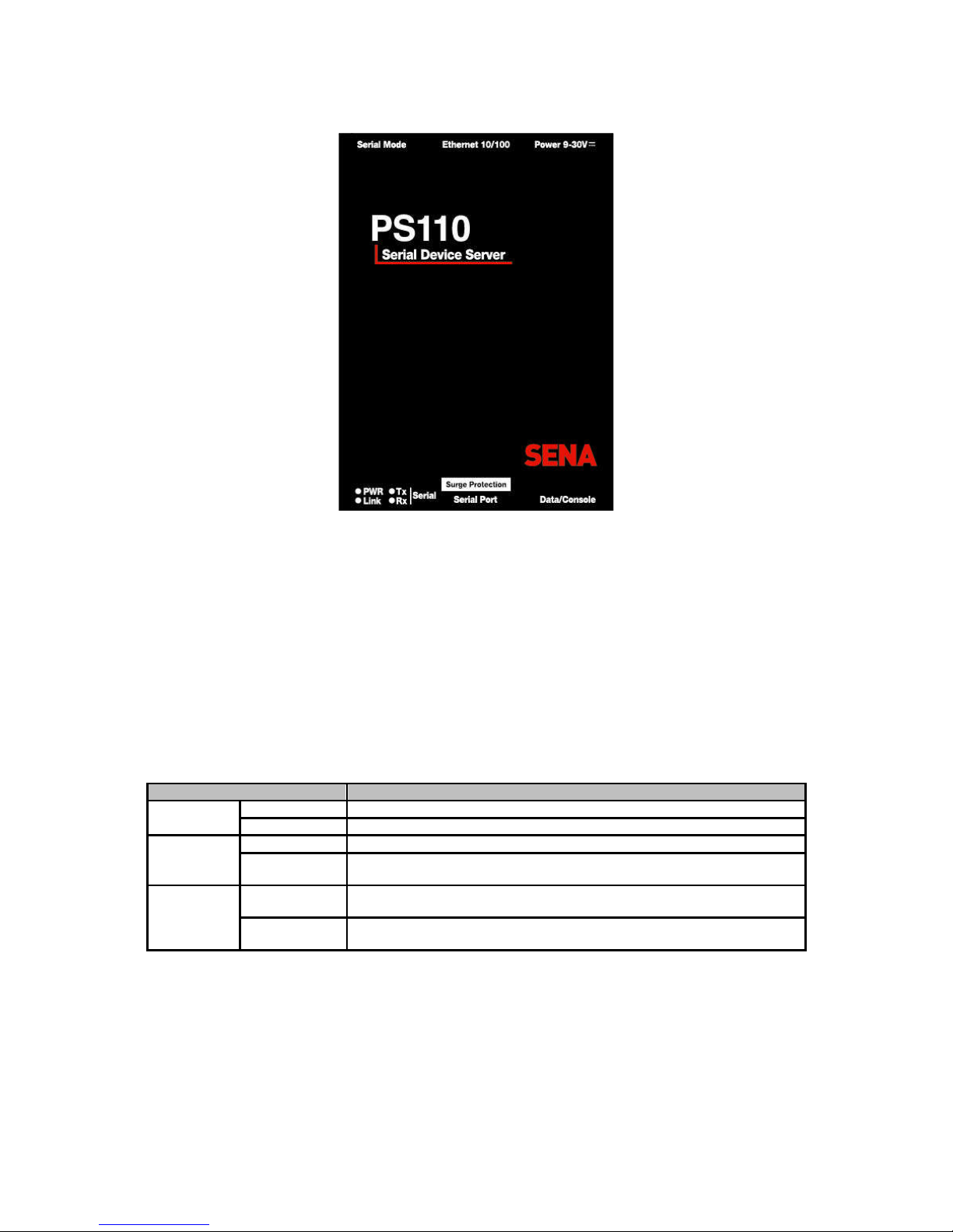
2.1.1. PS110 Panel Layout
The PS110 has four LED indicator lamps for status display. Upper-left lamp indicates the system
power-on status. Lower-left lamp indicates the 10/100Base Ethernet Link status. Right two lamps
indicate Receive and Transmit of the serial port.
There is a factory reset switch bottom panel of PS110 and the user can use this switch to restore
factory default configuration.
There is also a DIP switch located next to the Ethernet connector to set communication type of serial
port. (Please refer to Section 4.2.6. Serial Port Parameters and Appendix 1. Connections for more
detail information of serial communication type and its connection)
User can also select console or data mode of serial port using the Data/Console switch located next to
the serial port. (Please refer to Section 2.2.5. Using The System Console for more detail information of
serial console access)
Table 2-1 LED indicator lamps of the PS 110
Lamps Function
Power
Turned on to RED if power is supplied
Status
Ethernet
Ready
Turned on to GREEN if system is connected to Ethernet network.
Rx
Blinks whenever there is any incoming data stream through the serial port of
the PS110
Serial port
Tx
Blinks whenever there is any outgoing data stream through the serial port of
the PS110
Page 13
13
Figure 2-1 The panel layout of the PS110
2.1.2. PS410/810 Panel Layout
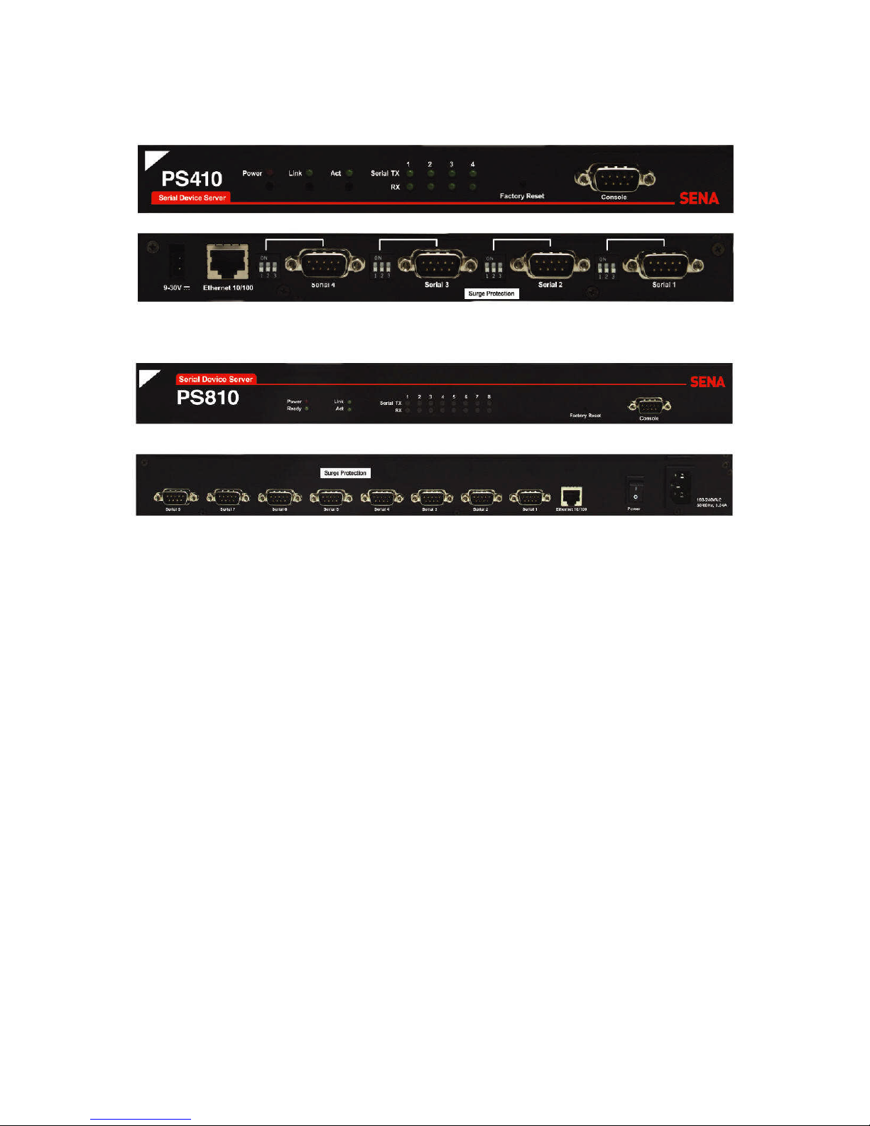
The PS410/810 has three groups of LED indicator lamps to display the status, as shown in Figure 2-2
and Figure 2-3 (i.e. System, Ethernet and Serial ports). The first two lamps on the left side indicate
Power, Ready(PS810 only). The next two lamps are for Ethernet Link and Act. Next lamps indicate
Receive and Transmit of the serial port. Table 2-2 describes the function of each LED indicator lamp.
Table 2-2 LED indicator lamps of the PS410/810
Lamps Function
Power
Turned on if power is supplied
System
Ready
Turned on if system is ready to run (PS810 only)
LINK
Turned on if connected to Ethernet network
Ethernet
Act
Blinks whenever there is any activities such as incoming or outgoing
packets through the Pro Series Ethernet port
Rx
Blinks whenever there is any incoming data stream through the serial port of
the Pro Series
Serial port
Tx
Blinks whenever there is any outgoing data stream through the serial port of
the Pro Series
There is a factory reset switch near by Serial console port and user can use this switch to restore
factory default configuration.
For PS410 there are 4 DIP switches to set communication type of serial port. (Please refer to Section
4.2.6. Serial Port Parameters and Appendix 1. Connections for more detail information of serial
communication type and its connection)
Page 14
14
Figure 2-2 The panel layout of the PS410
Figure 2-3 The panel layout of the PS810
2.2. Connecting The Hardware
This section describes how to connect the Pro Series to your equipment for initial testing.
- Connect the Pro Series to an Ethernet hub or switch
- Connect the device
- Connect the provided power source to the Pro Series
2.2.1. Connecting To The Network
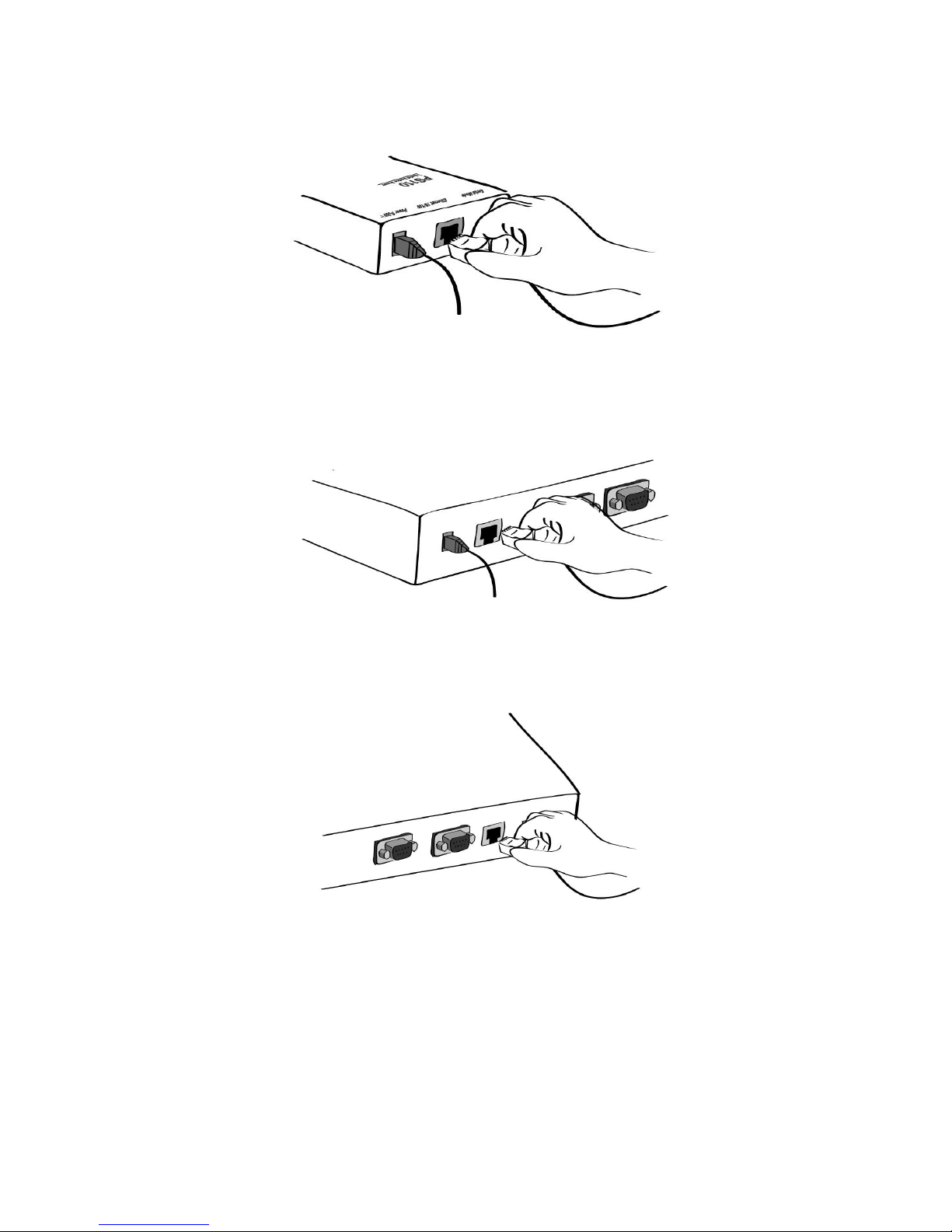
Plug one end of the Ethernet cable to the Pro Series Ethernet port. The other end of the Ethernet
cable should be connected to a network port. If the cable is properly connected, the Pro Series will
have a valid connection to the Ethernet network. This will be indicated by:
- The [Link] lamp will light up green.
- The [Act] lamp will blink to indicate incoming/outgoing Ethernet packets
Page 15
15
Figure 2-4 Connecting a network cable to the PS110
Figure 2-5 Connecting a network cable to the PS410
Figure 2-6 Connecting a network cable to the PS810
2.2.2. Connecting To The Device
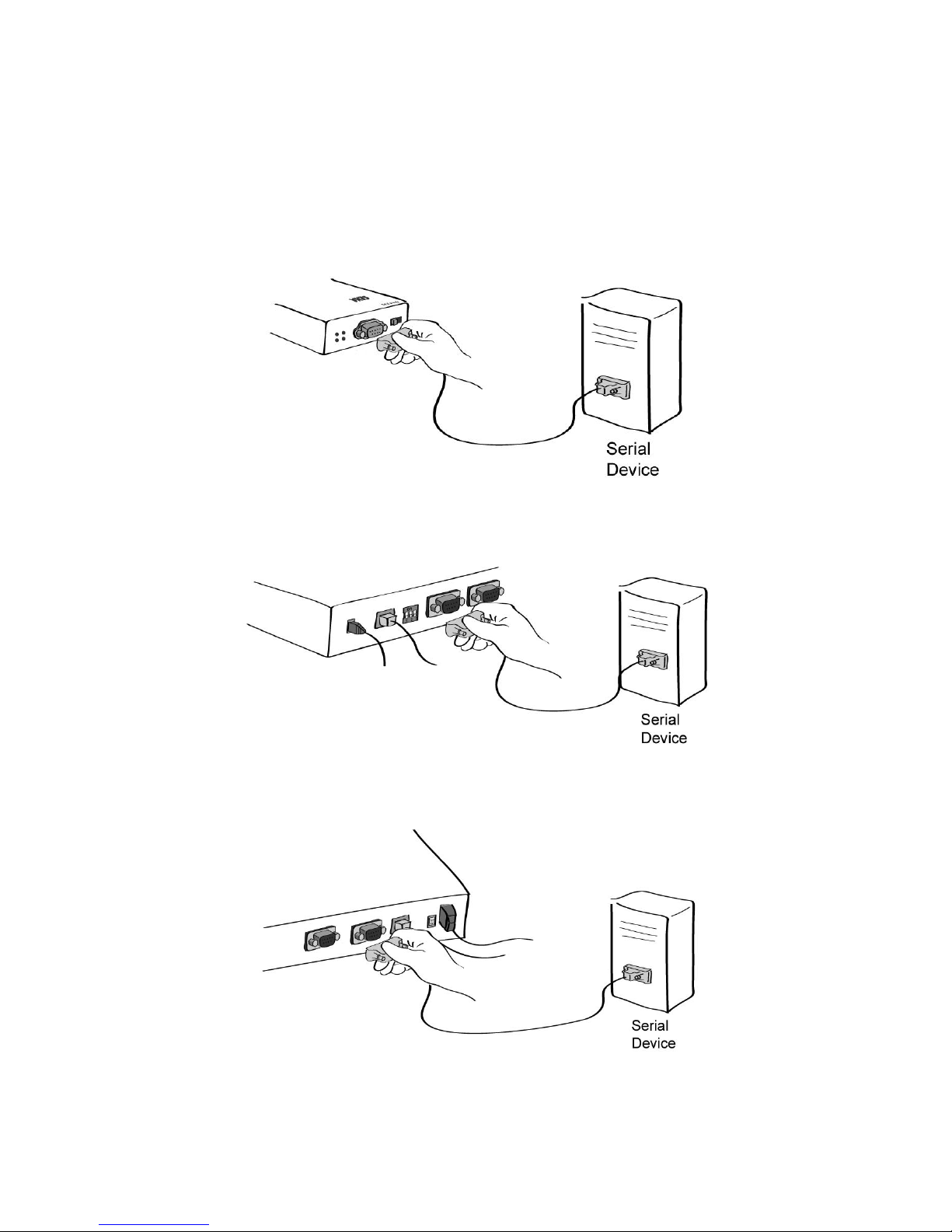
Connect the console cable to the Pro Series serial port. To connect to the console port of the device,
the user needs to consider the type of console port provided by the device itself. Please refer to the
Appendix 1. Connections for details.
Page 16
16
Note: If the configuration of the PS110 through the serial console is required, connect the serial cable
to the serial port of user’s computer first. And push the Data/Console switch to the Console side. And
also please set the position of DIP switch for serial mode to RS-232 mode. Configuration of the PS110
is discussed on Section 2.2.5. Using The System Console.
Figure 2-7 Connecting a equipment to the PS110
Figure 2-8 Connecting a equipment to the PS410
Figure 2-9 Connecting a equipment to PS810(Right)
Page 17
17
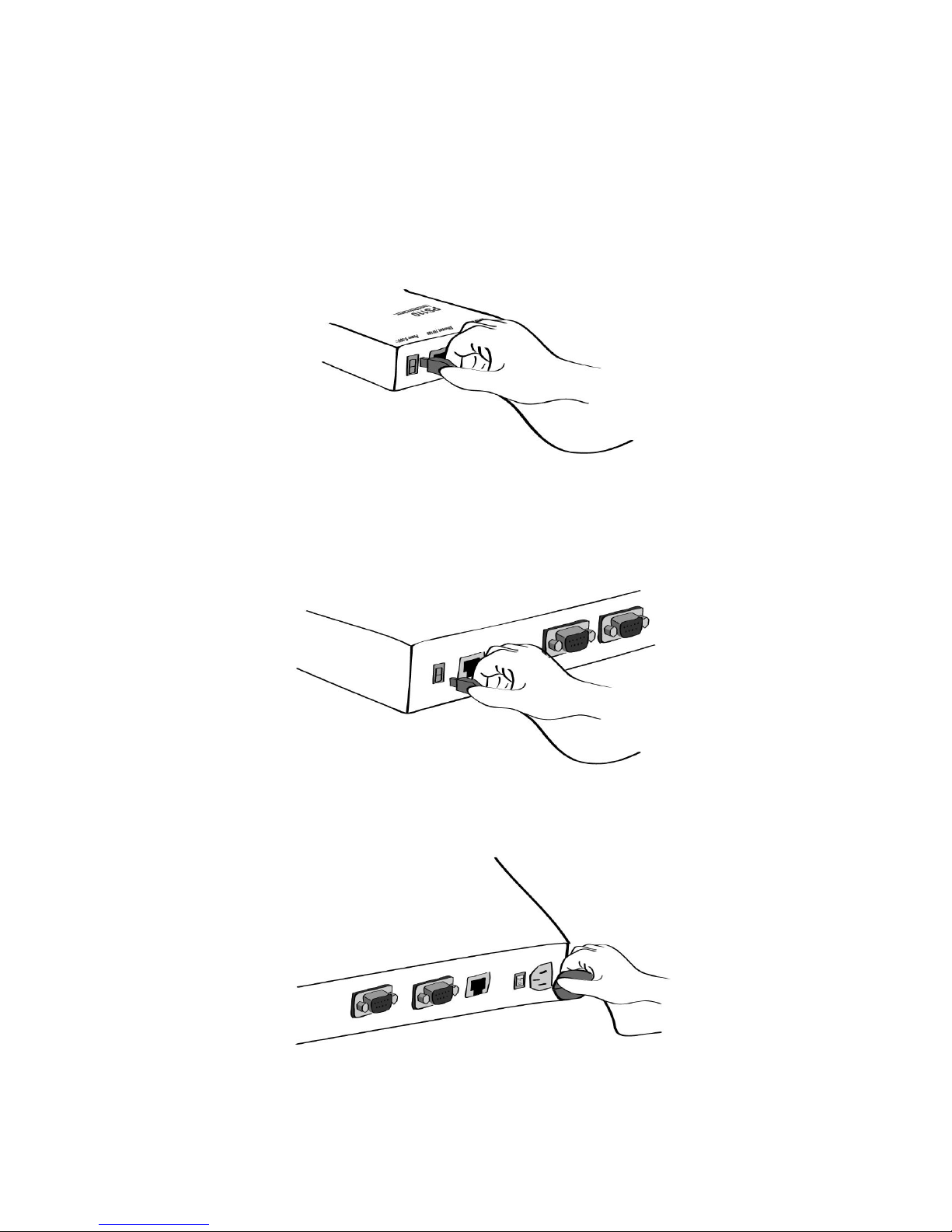
2.2.3. Connecting The Power
Connect the power cable to the Pro Series. If the power is properly supplied, the [Power] lamp will light
up solid red.
Figure 2-10 Connecting the power to the PS110
Figure 2-11 Connecting the power to the PS410
Figure 2-12 Connecting the power to the PS810
Page 18

18
2.2.4. Accessing The System Console
There are several ways to access the Pro Series. These methods are dependent on whether the user
is located at a local site or a remote site, or whether the user requires a menu-driven interface, graphic
menu system or CLI (Command Line Interface).
System console:
Local users can connect directly to the system console port of the Pro Series using the serial
console cable.
Remote console:
Remote users who require a menu-driven interface can utilize Telnet (port 23) or SSH (port 22)
connections to the Pro Series using Telnet or SSH client.
Note: Please note that Pro Series supports only the SSH v2, so user must use the SSH client
which is able to support SSH v2.
Web:
Remote users who want to use a web browser to configure the Pro Series can connect to the Pro
Series using a conventional web browser, such as Internet Explorer or Netscape Navigator.
The above methods require user authentication by the Pro Series system.
2.2.5. Using The System Console
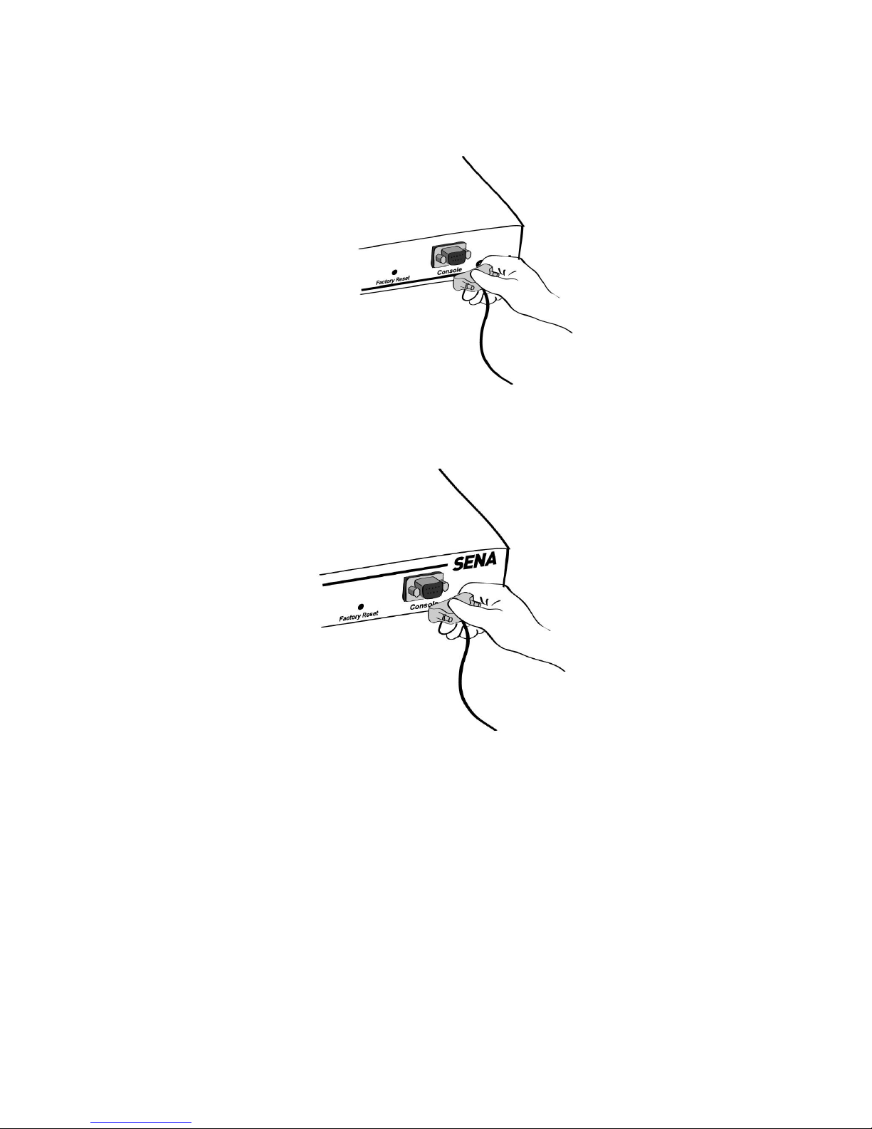
1) Connect one end of the console cable to the console port on the Pro Series.
(For PS110, Push the Data/Console switch to the Console side. And also please set the
position of DIP switch for serial mode to RS-232 mode. Configuration of DIP switch is
discussed on Appendix 1. Connections.)
Figure 2-13 Connecting a system console cable to the PS110
Page 19
19
Figure 2-14 Connecting a system console cable to the PS410
Figure 2-15 Connecting a system console cable to the PS810
2) Connect the other end of the cable to the serial port of the user’s computer.
3) Run a terminal emulator program (i.e. HyperTerminal). Set the serial configuration
parameters of the terminal emulation program as follows:
9600 Baud rate
Data bits 8
Parity None
Stop bits 1
No flow control
4) Press the [ENTER] key.
Page 20

20
5) Enter your username and password to log into the Pro Series. The factory default user
settings are as follows.
Login: root Password: root
ProSeries login: root
Password:
#
6) After login, user can use various shell commands in the CLI(Command Line interface). For
details on the CLI, refer to the chapter 7 CLI Guide.
7) “editconf” command will allow you to enter the text-menu driven interface and the menu
screen in # editconf
_] / [________________________________________________________________________
1. Network configuration
2. Serial port configuration
3. System administration
________________________________________________________________________________
COMMAND (Display HELP : help)>save
COMMAND (Display HELP : help)>apply
COMMAND (Display HELP : help)>help
_] HELP [_____________________________________________________________________
[Enter] refresh
[ESC] cancel or go to upper
/ go to root
.. go to upper
clear clear screen
pwd display path to current menu
save save current configuration
apply apply current configuration
help display this
exit exit
________________________________________________________________________________
COMMAND (Display HELP : help)>[Enter]
_] / [________________________________________________________________________
1. Network configuration
2. Serial port configuration
3. System administration
________________________________________________________________________________
COMMAND (Display HELP : help)>
8) Figure 2-16 is displayed.
# editconf
_] / [________________________________________________________________________
1. Network configuration
2. Serial port configuration
3. System administration
________________________________________________________________________________
COMMAND (Display HELP : help)>save
COMMAND (Display HELP : help)>apply
COMMAND (Display HELP : help)>help
_] HELP [_____________________________________________________________________
[Enter] refresh
[ESC] cancel or go to upper
/ go to root
Page 21

21
.. go to upper
clear clear screen
pwd display path to current menu
save save current configuration
apply apply current configuration
help display this
exit exit
________________________________________________________________________________
COMMAND (Display HELP : help)>[Enter]
_] / [________________________________________________________________________
1. Network configuration
2. Serial port configuration
3. System administration
________________________________________________________________________________
COMMAND (Display HELP : help)>
Figure 2-16 The main menu screen
From the main menu screen, the users may select a menu item for configuration of the Pro Series
parameters by selecting the menu number and pressing the [ENTER] key. In the submenu screen,
users can configure the required parameters guided by online comments. All the parameters can be
stored into the non-volatile memory space of the Pro Series, but the settings will not be stored until
users enter ”save” command on the menu. All the configuration change will be effective after entering
“apply” command on the menu.
2.2.6. Using Remote Console
The IP address of the Pro Series must be known before users can access the Pro Series using the
Remote console (see chapter 3 Network Configuration for details). The default IP address of Pro
Series is 192.168.161.5.
The Remote console access function can be disabled in the remote host access option (3.5 IP
Filtering for details).
The following instructions will assist in setting up the Remote Console functionality:
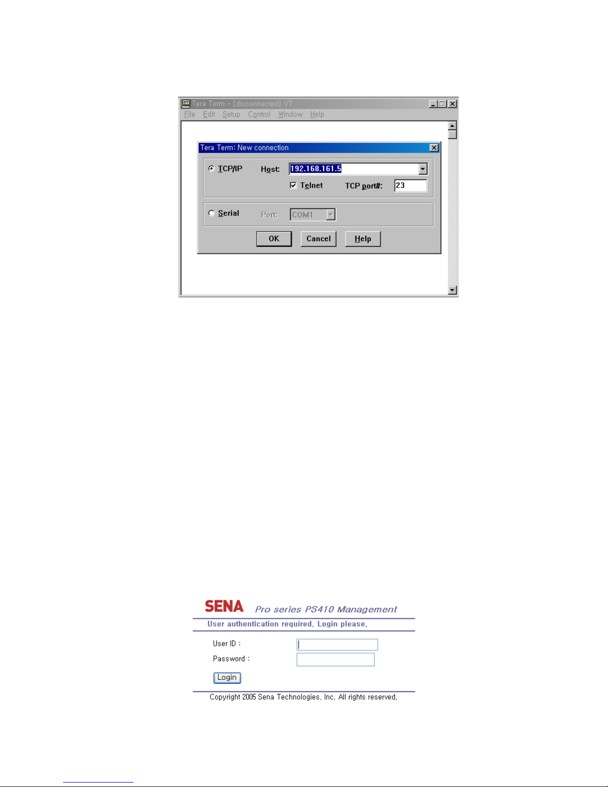
1) Run either a Telnet program or a program that supports Telnet functions (i.e. TeraTerm-Pro
or HyperTerminal). The target IP address and the port number must match the Pro Series. If
required, specify the port number as 23. Type the following command in the command line
interface of user’s computer.
telnet 192.168.161.5
Or run a Telnet program with the following parameters:
Page 22
22
Figure 2-17 Telnet program set up example (TeraTerm Pro)
2) The user must log into the Pro Series. Type the user name and password. A factory default
settings of the user name and password for CLI login are both root.
3) After entering correct user name and password, user can see the CLI prompts.
2.3. Accessing The Web Browser Management Interface
The Pro Series supports both HTTP and HTTPS (HTTP over SSL) protocols. The Pro Series also
contains its own Web management utility. To access the Pro Series Web management utility, enter
the IP address or resolvable hostname of the Pro Series into the web browser’s URL/Location field.
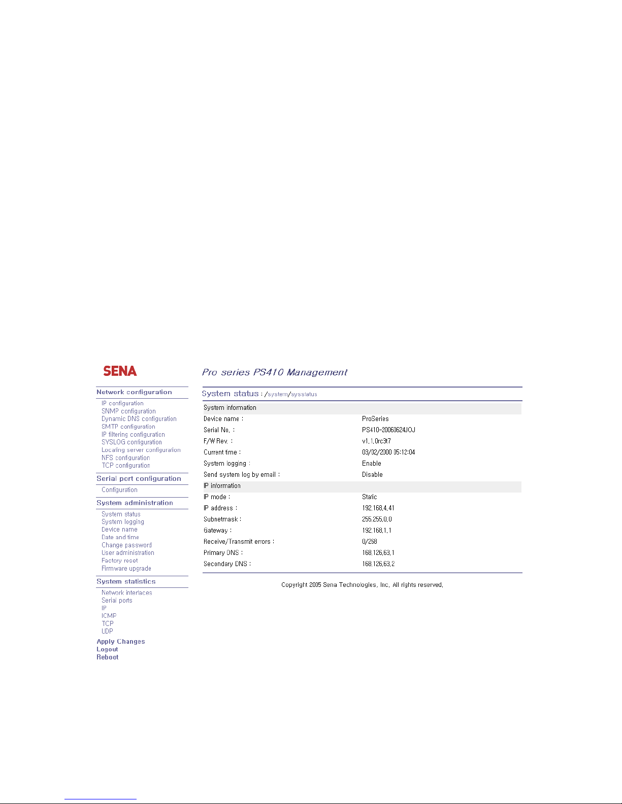
This will direct the user to the Pro Series login screen. The user must authenticate themselves by
logging into they system with a correct user name and password. The factory default settings are:
Login: root Password: root
Note: Before accessing the Pro Series Web management page, the user must check the IP address
(or resolvable Hostname) of the Pro Series and Subnet mask settings.
Page 23
23
Figure 2-18 Login screen of the Pro Series web management
Figure 2-19 shows the configuration homepage of the Pro Series Web management interface. A menu
bar is provided on the left side of the screen. The menu bar includes the uppermost configuration
menu groups. Selecting an item on the menu bar opens a tree view of all the submenus available
under each grouping. Selecting a submenu item will allow the user to modify parameter settings for
that item. Every page will allow the user to [Save], [Save & apply] or [Cancel] their actions. After
changing the configuration parameter values, the users must select [Save] to save the changed
parameter values to the non-volatile memory. To apply all changes made, the user must select
[Apply Changes]. This option is available on the bottom of the menu bar. Only when the user selects
[Apply changes] will the new parameter values be applied to the Pro Series configuration. The user
also can select [Save & apply] to save parameters and apply changes in one step.
If the user does not want to save the new parameter values, the user must opt to [Cancel]. All changes
made will be lost and the previous values restored. But the changes that are already saved or applied
cannot be canceled.
Figure 2-19 The Pro Series web management screen
Page 24
24
3. Network Configuration
3.1. IP Configuration
The Pro Series requires a valid IP address to operate within the user’s network environment. If the IP
address is not readily available, contact the system administrator to obtain a valid IP address for the
Pro Series. Please note that the Pro Series requires a unique IP address to connect to the user’s
network.
The users may choose one of three Internet protocols in setting up the Pro Series IP address: i.e.,
Static IP
DHCP (Dynamic Host Configuration Protocol)
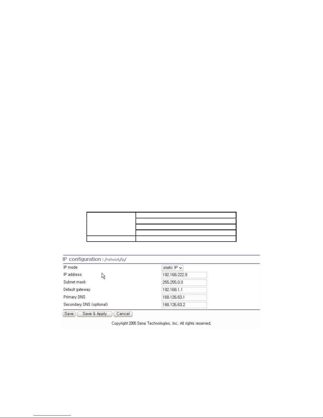
The Pro Series is initially defaulted to STATIC mode, with a static IP address of 192.168.161.5. Table
3-1 shows the configuration parameters for all three IP configurations. Figure 3-1 shows the actual
web-based GUI to change the user’s IP configuration.
Table 3-1 IP configuration Parameters
IP address
Subnet mask
Default gateway
Static IP
Primary DNS/ Secondary DNS
DHCP
Primary DNS/ Secondary DNS (Optional)
Figure 3-1 IP Configuration
Page 25

25
3.1.1. Using A Static IP Address
When using a Static IP address, the user must manually specify all the configuration parameters
associated with the IP address of the Pro Series. These include the IP address, the network subnet
mask, the gateway computer and the domain name server computers. This section will look at each of
these in more detail.
Note: The Pro Series will attempt to locate all this information every time it is turned on.
IP address
A Static IP address acts as a “static” or permanent identification number. This number is assigned to
a computer to act as its location address on the network. Computers use these IP addresses to
identify and talk to each other on a network. Therefore, it is imperative that the selected IP address be
both unique and valid in a network environment.
Note: 192.168.1.x will never be assigned by and ISP (Internet Service Provider). IP addresses using
this form are considered private. Actual applications of the Pro Series may require access to public
network, such as the Internet. If so, a valid public IP address must be assigned to the user’s computer.
A public IP address is usually purchased or leased from a local ISP.
Subnet mask
A subnet represents all the network hosts in one geographic location, such as a building or local area
network (LAN). The Pro Series will use the subnet mask setting to verify the origin of all packets. If
the desired TCP/IP host specified in the packet is in the same geographic location (on the local
network segment) as defined by the subnet mask, the Pro Series will establish a direct connection. If
the desired TCP/IP host specified in the packet is not identified as belonging on the local network
segment, a connection is established through the given default gateway.
Default gateway
A gateway is a network point that acts as a portal to another network. This point is usually the
computer or computers that control traffic within a network or a local ISP (Internet service provider).
The Pro Series uses the IP address of the default gateway computer to communicate with hosts
outside the local network environment. Refer to the network administrator for a valid gateway IP
address.
Primary and Secondary DNS
The DNS (Domain Name System) server is used to locate and translate the correct IP address for a
requested web site address. A domain name is the web address (i.e. www.yahoo.com) and is usually
easier to remember. The DNS server is the host that can translate such text-based domain names into
Page 26

26
the numeric IP addresses for a TCP/IP connection.
The IP address of the DNS server must be able to access the host site with the provided domain
name. The Pro Series provides the ability to configure the required IP addresses of both the Primary
and Secondary DNS servers addresses. (The secondary DNS server is specified for use when the
primary DNS server is unavailable.)
3.1.2. Using DHCP
Dynamic Host Configuration Protocol (DHCP) is a communications protocol that lets network
administrators manage and automate the assignment of IP addresses centrally in an organization’s
network. DHCP allows the network administrator the ability to supervise and distribute IP addresses
from a central point and automatically send a new IP address when a computer is plugged into a
different network location.
When in static IP mode, the IP address must be entered manually at each computer. If a computer is
moved to another network location, a new IP address must be assigned. DHCP allows all the
parameters, including the IP address, subnet mask, gateway and DNS servers to be automatically
configured when the IP address is assigned. DHCP uses a “lease” concept in assigning IP
addresses to a computer. It limits the amount of time a given IP address will be valid for a computer.
All the parameters required to assign an IP address are automatically configured on the DHCP server
side, and each DHCP client computer receives this information when the IP address is provided at its
boot-up.
Each time the device is reset, the Pro Series broadcasts a DHCP request over the network. The reply
generated by the DHCP server contains the IP address, as well as the subnet mask, gateway address,
DNS servers and the “lease” time. The Pro Series immediately places this information in its memory.
Once the “lease” expires, the Pro Series will request a renewal of the “lease” time from the DHCP
server. If the DHCP server approves the request for renewal, the Pro Series can continue to work
with the current IP address. If the DHCP server denies the request for renewal, the Pro Series will start
the procedure to request a new IP address from the DHCP server.
Note: While in DHCP mode, all network-related parameters for the Pro Series are to be configured
automatically, including the DNS servers
A DHCP sever assigns IP addresses dynamically from an IP address pool, which is managed by the
network administrator. This means that the DHCP client, i.e. the Pro Series, receives a different IP
address each time it boots up. The IP address should be reserved on the DHCP server side to assure
that the user always knows the newly assigned Pro Series address. In order to reserve the IP address
in the DHCP network, the administrator needs the MAC address of the Pro Series found on the label
sticker at the bottom of the Pro Series.
Page 27
27
3.2. SNMP Configurations
The Pro Series has the SNMP (Simple Network Management Protocol) agent supporting SNMP v1
and v2 protocols. Network managers like NMS or SNMP Browser can exchange information with Pro
Series, as well as access required functionality.
SNMP protocols include GET, SET, GET–Next, and TRAPs. With these functions, a manager can be
notified of significant events (TRAPs), query a device for more information (GET), and make changes
to the device state (SET). SNMPv2 adds a GET–Bulk function for retrieving tables of information and
security functions.
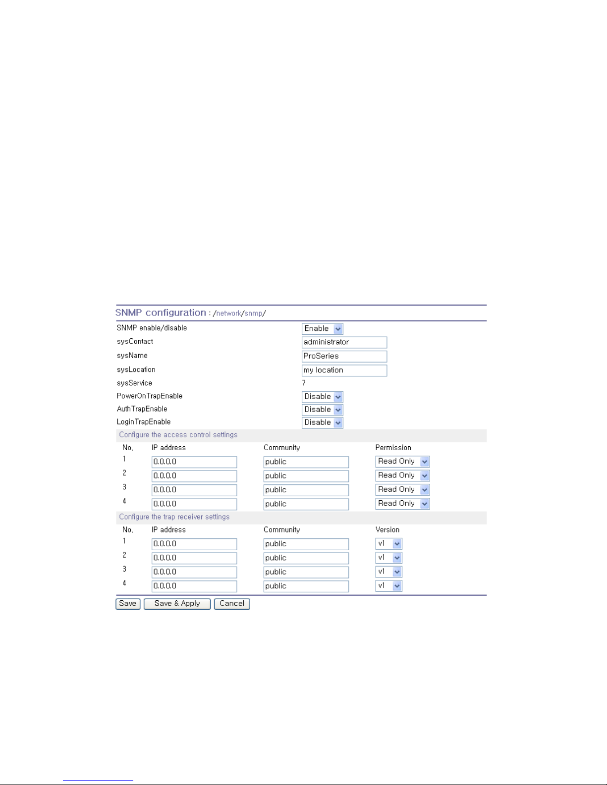
With the SNMP configuration panel, the user can configure MIB-II System objects, access control
settings and TRAP receiver settings. The manager configured in this menu can perform both
information exchange and action control. Figure 3-2 shows a SNMP configuration screen via a web
interface.
Figure 3-2 SNMP Configuration
3.2.1. MIB-II System Objects Configuration
MIB–II System objects configuration sets the System Contact, Name, Location, and Authenticationfailure traps used by the SNMP agent of the Pro Series. These settings provide the values used for the
MIB-II sysName, sysContact, sysLocation, sysService and enableAuthenTrap.
Page 28

28
Brief descriptions of each object are as follows,
sysContact:
Identification of the contact person for the managed system (Pro Series), and a description of how to
contact the person.
sysName:
Name used to identify the system. By convention, this is the fully qualified domain name of the node.
sysLocation:
The physical location of the system (e.g., Room 384, Operations Lab, etc.).
sysService(Read Only):
A series of values, separated by commas, that indicate the set of services that the system provides. By
default, Pro Series only supports an Application(7) service level.
EnablePoweronTraps:
Indicates whether the SNMP agent process is permitted to generate power-on traps.
EnableAuthenTrap:
Indicates whether the SNMP agent process is permitted to generate authentication-failure traps. The
value of this object overrides any configuration information; as such, it provides a means whereby all
authentication-failure traps may be disabled..
EnableLoginTrap:
Indicates whether the SNMP agent process is permitted to generate system login traps for console,
telnet and Web access.
If users need support for adding or modifying MIBs, please contact Sena technical support.
For more information about the MIBs and SNMP, see the RFCs 1066, 1067, 1098, 1317, 1318 and
1213.
3.2.2. Access Control Configuration
Access Control defines accessibility of managers to the Pro Series SNMP agent. Only the manager
set in this menu can access Pro Series SNMP agent to exchange information and control actions. If
there is no specified IP address (all IP address are defaulted to 0.0.0.0), a manager from any host can
access the Pro Series SNMP agent.
Page 29
29
3.2.3. Trap Receiver Configuration
The Trap receiver defines managers, which can be notified of significant events (TRAP) from the Pro
Series SNMP agent.
3.2.4. Management Using SNMP
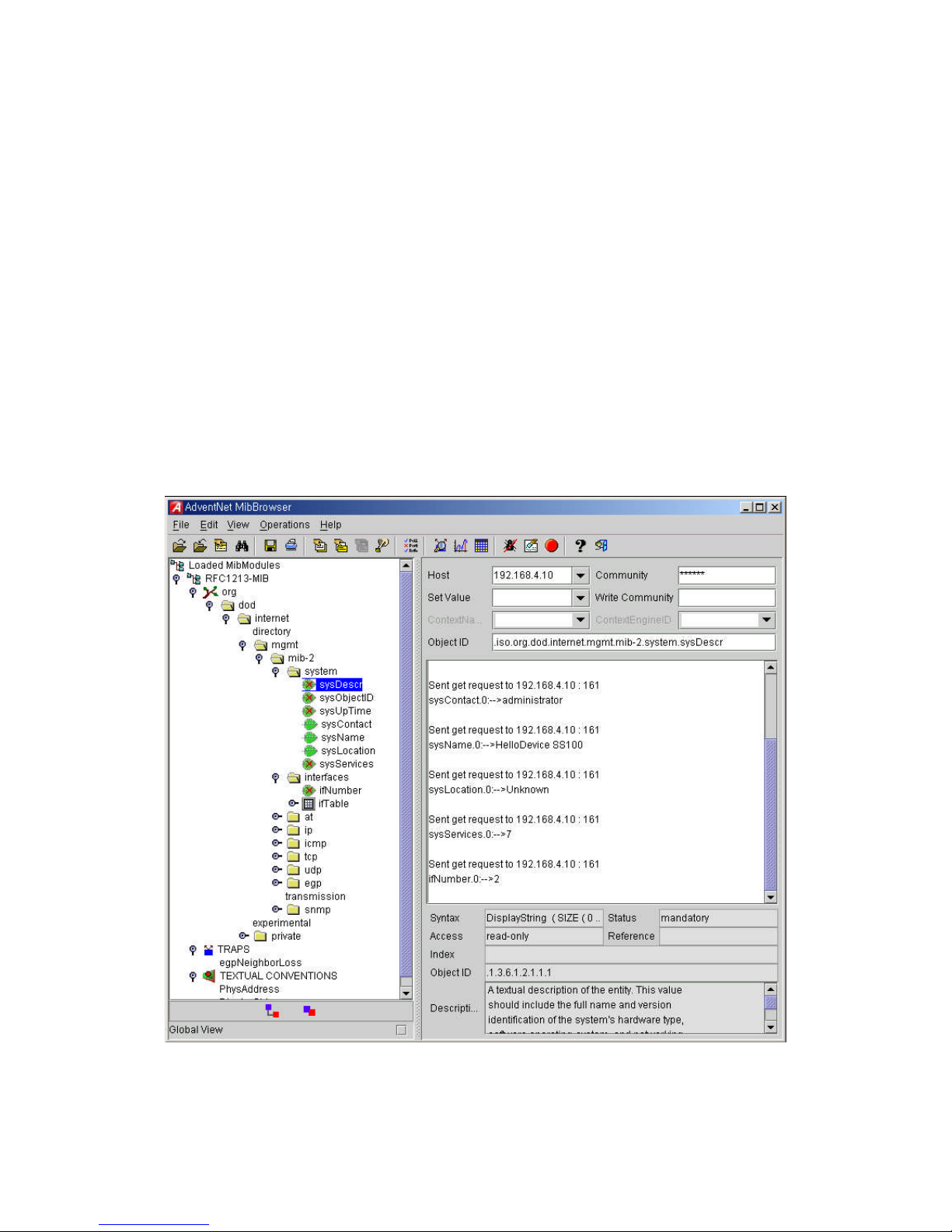
The Pro Series can be managed through the SNMP protocol using NMS (Network Management
System) or SNMP Browser. Before using the NMS or SNMP Browser, the user must set the access
control configuration properly so that the Pro Series permits host access where the NMS or SNMP
Browser is executed. Figure 3-3 shows a screen shot of a typical SNMP browser with MIB-II OIDs of
the Pro Series SNMP agent.
Figure 3-3 Browsing MIB-II OIDs of Pro Series SNMP agent using SNMP Browser
(AdventNet MibBrowser)
Page 30
30
3.3. Dynamic DNS Configuration
When users connect the Pro Series to a DSL line or use a DHCP configuration, the IP address might
be changed whenever it reconnects to the network. It can therefore be very difficult to post all related
contacts for each new IP address. In addition, if the administrator only has access through the remote
console, there is no way to know if an IP address has changed, or what the new IP address is.
A Dynamic DNS service is provided by various ISPs or organizations to deal with the above issue. By
using the Dynamic DNS service, users can access the Pro Series through the hostname registered in
the Dynamic DNS Server regardless of any IP address change.
By default, the Pro Series only supports Dynamic DNS service offered at Dynamic DNS Network
Services, LLC (www.dyndns.org). Contact Sena technical support for issues regarding other Dynamic
DNS service providers.
To use the Dynamic DNS service provided by Dynamic DNS Network Services, the user must set up
an account in their Members’ NIC (Network Information Center - http://members.dyndns.org). The user
may then add a new Dynamic DNS Host link after logging in to their Dynamic DNS Network Services
Members NIC.
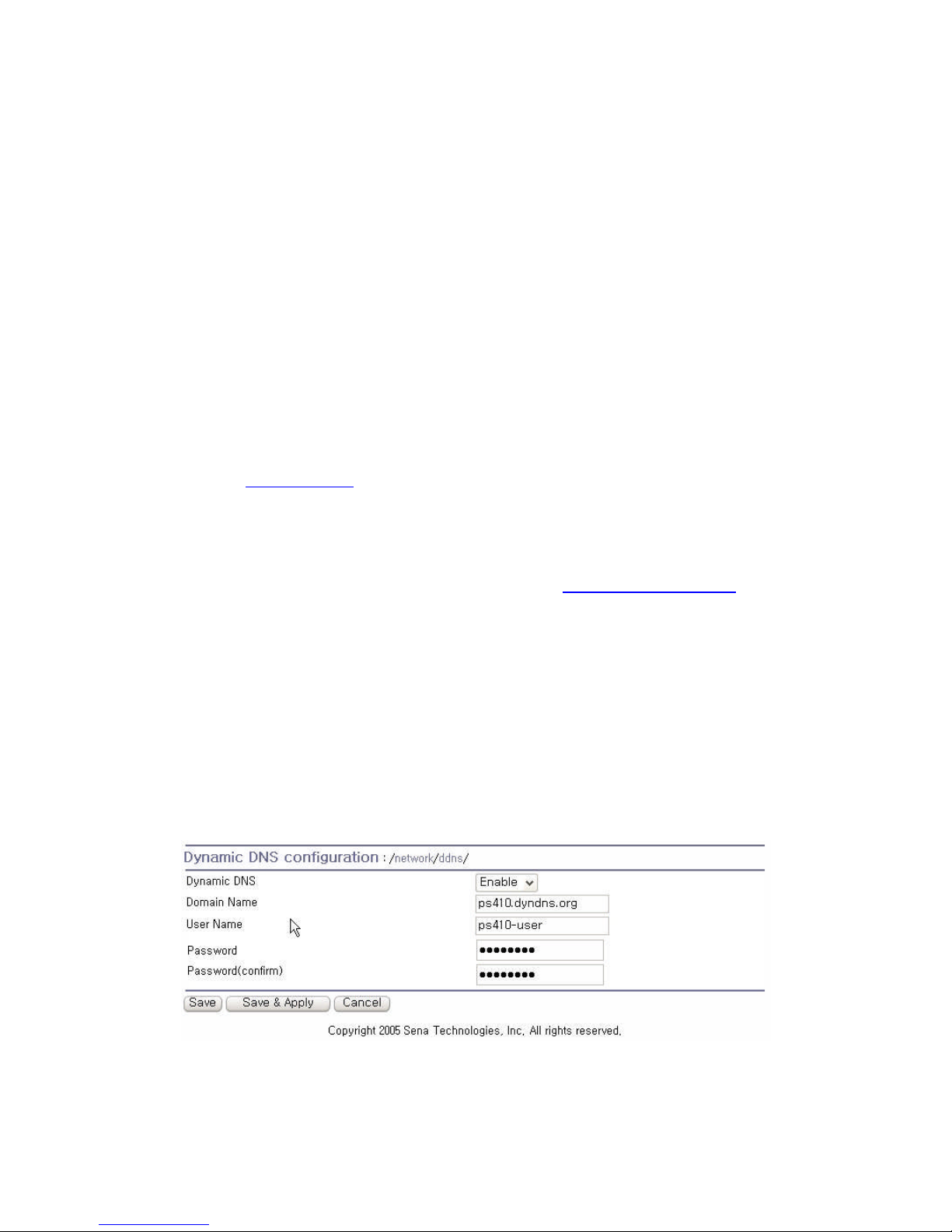
After enabling the Dynamic DNS service in the Dynamic DNS Configuration menu, the user must enter
the registered Domain Name, User Name, and Password. After applying the configuration change,
users can access the Pro Series using only the Domain Name.
Figure 3-4 shows the Dynamic DNS configuration web interface.
Figure 3-4 Dynamic DNS Configuration
Page 31
31
3.4. SMTP Configuration
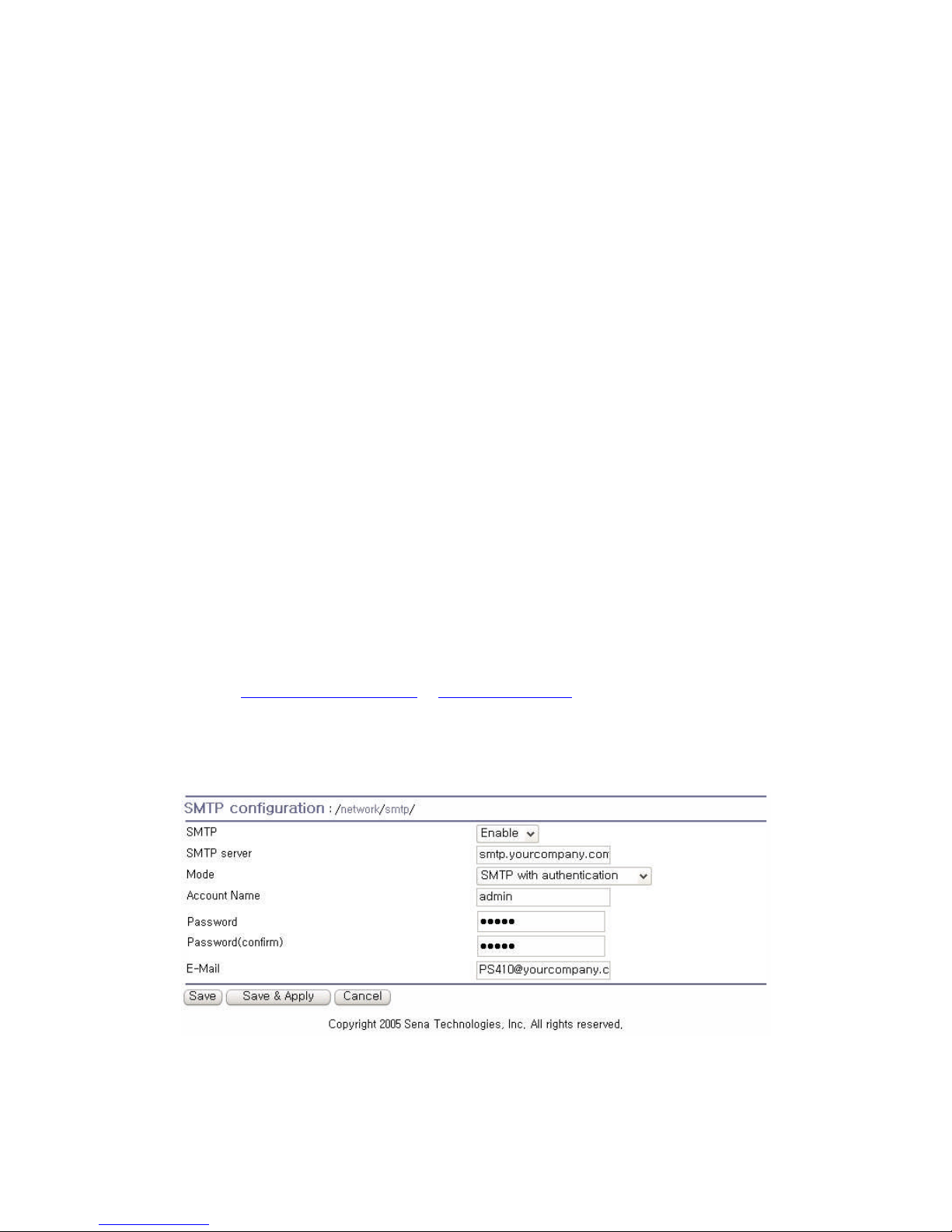
The Pro Series can send an email notification when the number of system log messages reaches to
certain value and/or when an alarm message is created due to an issue with serial port data. The user
must configure a valid SMTP server send these automatically generated emails. The Pro Series
supports three SMTP server types:
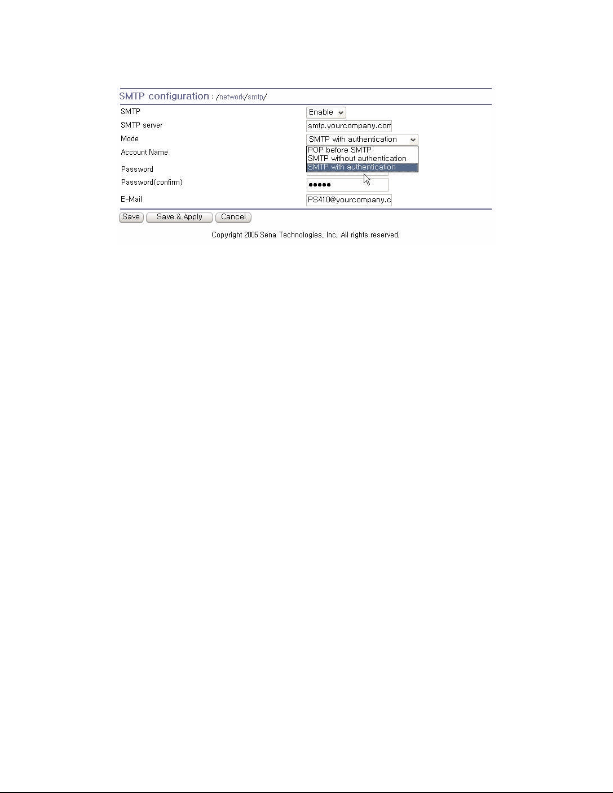
SMTP without authentication
SMTP with authentication
POP-before-SMTP
These examples can be seen in Figure 3-6. Required parameters for each SMTP configuration
include:
SMTP server IP address
SMTP user name
SMTP user password
Device mail address
The device mail address specifies the sender’s email address for all log and alarm delivery emails.
SMTP servers often check only the sender’s host domain name of the email address for validity.
Consequently, the email address set for the device can use an arbitrary username with a registered
hostname (i.e. [email protected] or [email protected]).
The SMTP user name and SMTP user password are required when either SMTP with authentication
or POP-before-SMTP mode is selected.
Figure 3-5 SMTP Configurations
Page 32
32
Figure 3-6 SMTP mode selection in SMTP configuration
3.5. IP Filtering
The Pro Series prevents unauthorized access using an IP address based filtering method. The users
can allow one of the following scenarios by changing the parameter settings:
- Any host cannot access a specific service of the Pro Series
- Only one host of a specific IP address can access a specific service of the Pro Series
- Hosts on a specific subnet can access a specific service of the Pro Series
- Any host can access a specific service of the Pro Series
The IP filtering feature is intended to control access to Telnet console, SSH console, NFS, Web server
or each port, which may be enabled or disabled. The factory default of the filtering feature is “All
services and ports are accessible from any host”.
The meanings of each parameter in IP filtering configuration are as follows,
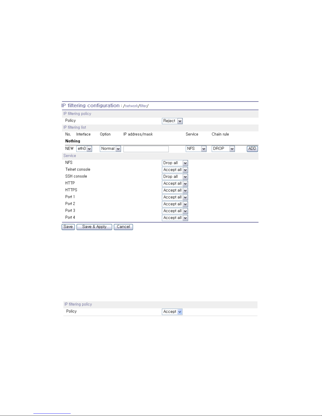
Interface
Apply IP filtering rule to the incoming packet of Pro Series. This is fixed parameter as eth0(Read-Only).
Option and IP address/mask
Input field to describe a specific range of host on the network. The user may allow a host or a group of
hosts to access the Pro Series. The user must then enter the IP address and subnet of access. Any
user on a remote host must stay in the specified subnet boundary to access the Pro Series. To allow
only a specific host to access the Pro Series, enter the IP address of the specific host and just give
255.255.255.255 for the subnet with Normal option. To allow any hosts to have access to the Pro
Series, give 0.0.0.0 for both of the IP address and subnet with Normal option also. Refer to Table 3-2
for more details.
Page 33
33
Service
Service to which will be applied to the IP filtering rule. User can select one of Telnet, SSH, NFS, HTTP,
HTTPS or each serial port.
Chain rule
Set the basic rule for the host to access the Pro Series as one of Accept, Drop or Reject.
Figure 3-7 IP filtering Configuration
The Pro Series provides a policy option. The policy decides how to treat a packet which isn’t
determined to be dropped or accepted by IP filtering list. For example, in case there is no IP filtering
list and all the services are set to be “Accept all”, the Pro Series won’t respond to any packet whose
destination port is not one of the services if the policy is “DROP” or “REJECT.
Figure 3-8 IP filtering policy
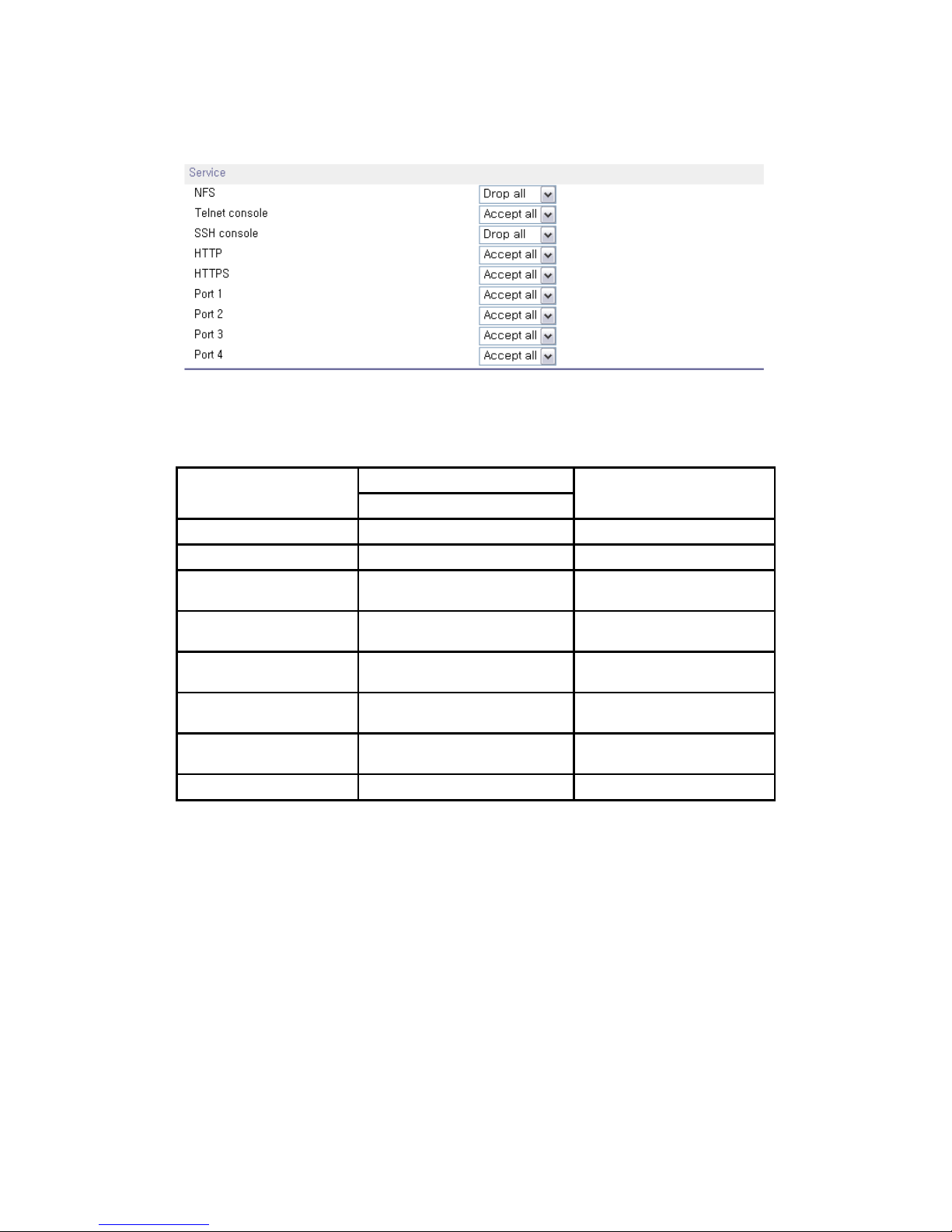
The Pro Series also provides users with simple configuration way to block a specific service(s) or
serial ports from all hosts. If the user should set any service option as “Drop all” or “Reject all”, then all
access to the service from the network will be blocked.
Page 34
34
Figure 3-9 IP filtering Configuration for each service and serial port
Table 3-2 Input examples of Option and IP address/mask combination
Input format
Allowable Hosts
IP address/mask
Option
Any host 0.0.0.0/0.0.0.0 Normal
192.168.1.120 192.168.1.120/255.255.255.255 Normal
Any host except
192.168.1.120
192.168.1.120/255.255.255.255 Invert
192.168.1.1 ~
192.168.1.254
192.168.1.0/255.255.255.0 Normal
192.168.0.1 ~
192.168.255.254
192.168.0.0/255.255.0.0 Normal
192.168.1.1 ~
192.168.1.126
192.168.1.0/255.255.255.128 Normal
192.168.1.129 ~
192.168.1.254
192.168.1.128/255.255.255.128 Normal
None 0.0.0.0/0.0.0.0 Invert
3.6. SYSLOG Server Configuration
The Pro Series supports the use of a remote message logging service, SYSLOG service for the
system and port data logging. To use the remote SYSLOG service, the user must specify the
SYSLOG server’s IP address and the facility to be used. Figure 3-10 shows the SYSLOG server
configuration page which is located in the Web interface.
Page 35

35
Figure 3-10 SYSLOG server configuration
To receive log messages from the Pro Series, the SYSLOG server must be configured as “remote
reception allowed”. If there is a firewall between the Pro Series and the SYSLOG server, there must
be a rule that allows all outgoing and incoming UDP packets to travel across the firewall.
The Pro Series supports SYSLOG facilities from local0 to local7. The user can employ these
facilities to save messages from the Pro Series separately in the SYSLOG server.
If the SYSLOG service is enabled and the SYSLOG server configuration is properly set up, the user
may configure the storage location for the system log or port data log of the Pro Series as SYSLOG
server. For more information about the configuration of port/system log storage location, please refer
to section, 4.2.8 Port Logging and 5.2 System Logging.
3.7. Locating Server
3.7.1. Overview
If users want the Pro Series to work as a server (TCP or UDP), the host acting as a client has to know
the IP address of the Pro Series. However, under the dynamic IP address environment such as DHCP,
arbitrary IP address can be assigned to the Pro Series, which means special consideration is required
to access the current IP address of it. To tackle this problem, the Pro Series can be configured to send
its IP address information whenever it is assigned a new IP address or periodically to a specific server
called locating server. You can operate a specific host as your locating server or you can use your
client host as a locating server simultaneously.
No special library or toolkit to implement locating server is provided. You have to implement your own
application by using the protocol provided below or contact us.
3.7.2. Locating Server Configuration
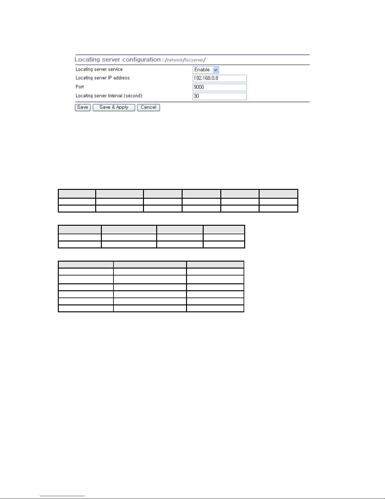
Locating server configuration screen is shown in Figure 3-11. You have to configure locating server
IP address, locating server UDP port number and connection time interval as well as to use locating
server feature or not. Initially locating server feature is configured as “Disabled”.
Page 36
36
Figure 3-11 Locating server configuration
3.7.3. Locating Server Communication Protocol
When the Pro Series sends its IP address information to the locating server, data format will be as
follows:
Description Magic Cookie Data(0) Data(1) … Data(n)
Bytes 4 Variable Variable Variable
Value F1-AA-AA-BC
Data(n) format
Description Data ID Length Data
Bytes 1 1 Variable
Value 1~6 Variable Variable
Data ID
ID Description Length
1 Device name var
2 Model name var
3 Serial number var
4 MAC address 6
5 IP address 4
6 Local ports* 1 or 4 or 8
Note: Local ports: Each 2 byte data represent current local port setting of the corresponding serial port. Local
ports data length of PS110 should be 2 bytes, while 8 bytes and 16 bytes for PS410 and PS810 respectively.
Configured local TCP (or UDP) port numbers for each serial port are filled in the serial port number order base,
(i.e. TCP or UDP port number for serial port 1 first). If serial port is disabled, the local port number of that serial
port is regarded as 0.
Example of the PS110:
If port number = 7001 (1B59h), Local ports data = 1Bh, 59h
If serial port is disabled, Local port data = 00h, 00h
Example of the PS410:
Port1 = 7001 (1B59h), Port2 = 7010 (1B62h), Port3 = Disable, Port4 = 7004(1B5Ch)
Local ports data = 1Bh, 59h, 1Bh, 62h, 00h, 00h, 1Bh, 5Ch
Page 37
37
3.8. NFS Server Configuration
The Pro Series supports NFS (Network File System) service for system or port data logging functions.
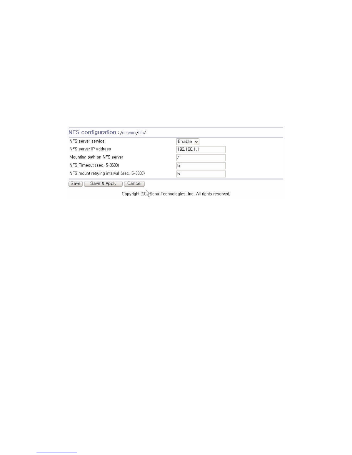
To use this service, the user must specify the IP address of a NFS server and the mounting path on
the NFS server. Figure 3-12 displays the NFS server configuration page located in the web
configuration interface..
Figure 3-12 NFS server configuration
To store the Pro Series log data to the NFS server, the NFS server must be configured as “read and
write allowed”. If there is a firewall between the Pro Series and the NFS server, there must be a rule
that allows all outgoing and incoming packets to travel across the firewall.
If the NFS service is enabled and the NFS server configuration is properly set up, the user may
configure the storage location for the system log or port data log of the If there is a firewall between
the Pro Series and the SYSLOG server, there must be a rule that allows all outgoing and incoming
UDP packets to travel across the Pro Series as the NFS server. For more information about the
configuration of the port/system log storage location, please refer to section, 4.2.8 Port Logging and
5.2 System Logging.
3.9. TCP Service Configuration
If a TCP session is established between two hosts, the connection should be closed (normally or
abnormally) by either of the hosts to prevent the lock-up of the corresponding TCP port. To prevent
this type of lock-up situation, the Pro Series provides a TCP “keep-alive” feature. The Pro Series will
send packets back and forth through the network periodically to confirm that the network exists . The
corresponding TCP session is closed automatically if there’s no response from the remote host.
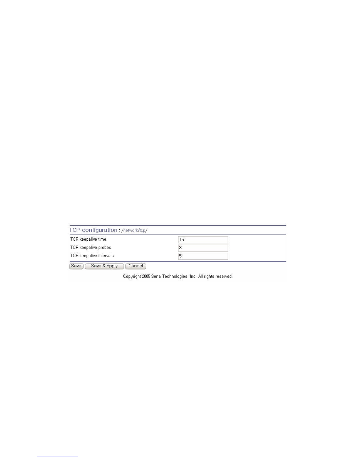
To use the TCP “keep-alive” feature with the Pro Series, the users should configure three parameters
as follows:
Page 38
38
TCP keep-alive time:
This represents the time interval between the last data transmission and keep-alive packet
submissions by the Pro Series. These “keep-alive” messages are sent to the remote host to confirm
that the session is still open. The default time value is 15 sec.
TCP “keep-alive” probes:
This represents how many “keep-alive” probes will be sent to the remote host, until it decides that the
connection is dead. Multiplied with the “TCP ‘keep-alive’ intervals”, this gives the time that a link is
forced to close after a “keep-alive” packet has been sent for the first time. The default is 3 times.
TCP keep-alive intervals:
This represents the waiting period until a “keep-alive” packet is retransmitted. The default value is 5
seconds.
By default, the Pro Series will send the keep-alive packets 3 times with 5 seconds interval after 15
seconds have elapsed since the time when there’s no data transmitted back and forth.
Figure 3-13 TCP keep-alive configuration
Page 39

39
4. Serial Port Configuration
4.1. Overview
The serial port configuration capability allows the user to configure the host mode of each port, serial
communication parameters, cryptography, port logging parameters and other related parameters.
The serial port’s host mode can be set as any of the following:
TCP :
The Pro Series operates as a TCP server and client. If the connection is not established, it accepts all
incoming connections from any registered remote hosts and connects to the registered remote hosts if
there is any data from the serial devices. Otherwise, it will send data back and forth. In summary, the
Pro Series will work as if it is virtually connected to the remote host.
UDP :
The UDP mode operation is similar to that of TCP mode except that it is based on UDP protocol.
Modem emulation :
Select this mode when the serial device becomes ready to support modem AT commands or users
want to perform the session control by using AT commands. Only TCP session is supported.
With the port-logging feature while in console server mode, the data sent through the serial port is
transferred to MEMORY or NFS server’s storage. The user can also define keywords for each serial
port that will trigger an email or SNMP trap notification. This will enable the user to monitor the data
from the attached device.
Using MEMORY to store data will result in loss of all information when the Pro Series is turned off.
Use the NFS server to preserve the serial port log data.
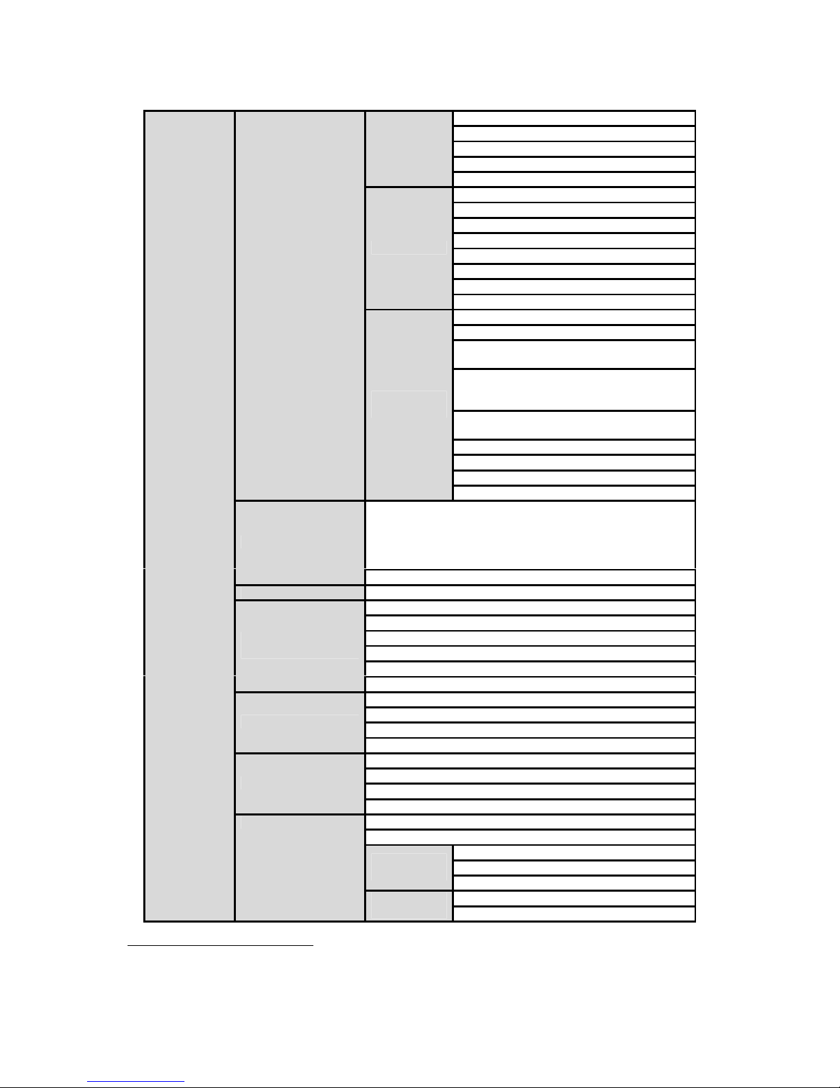
The serial ports can be configured individually or all at once. Table 4-1 summarizes the configuration
parameters related to the serial port configuration.
Table 4-1 Serial port configuration parameters
Port Enable/Disable
Port title
Port number
User authentication
Telnet support
Max allowed connection
Cyclic connection
Inactivity timeout (0 for unlimited)
All serial
ports
setting
Or
Individual
serial port
setting
#1~#8(1/4)
Host mode TCP
Socket ID (for outgoing connection)
Page 40
40
TCP Nagle algorithm Enable/Disable
DTR option
Allow incoming connection
When DSR goes low
When DSR goes high
Port number
Max allowed connection
Inactivity timeout (0 for unlimited)
Socket ID (for outgoing connection)
Accept unlisted
Send unlisted
DTR option
UDP
DSR behavior
DTR option
DSR behavior
Phone number to host address mapping
table
CONNECT string in non-verbose mode
(ATV0) and CONNECT string in verbose
mode (ATV1)
Response to AT&Cn, AT&Wn and AT&Zn
with
Command echo delay (ms)
Default command echo
Default data mode
Modem
emulation
Init string
Add or Edit a remote host
2
Host IP address
Host port
Backup host IP address
Backup host port
Remote host
1
Remove a remote host
Cryptography
3
SSLv3
Baud rate
Data bits
Parity
Stop bits
Flow control
Serial port
parameters
Inter-character timeout (ms)
Enable/Disable modem
Modem init-string
DCD behavior
Modem
Automatic release modem connection
Enable/Disable Port logging
Port log storage location
Port log buffer size
Port logging
Display port log
Enable/Disable port event handling
Notification interval
Enable/Disable Email notification
Subject of Email
Email
notification
Recipient’s Email address
Enable/Disable SNMP notification
Port event handling
SNMP
notification
Subject of SNMP trap
1
TCP/UDP mode only.
2
A backup host and port are used when connection to main host is failed
3
TCP mode only
Page 41
41
SNMP trap receiver’s IP address
SNMP trap community
SNMP trap version
Add/Edit an event keyword
Event keyword
Email notification
SNMP trap notification
Port command
Remove a keyword
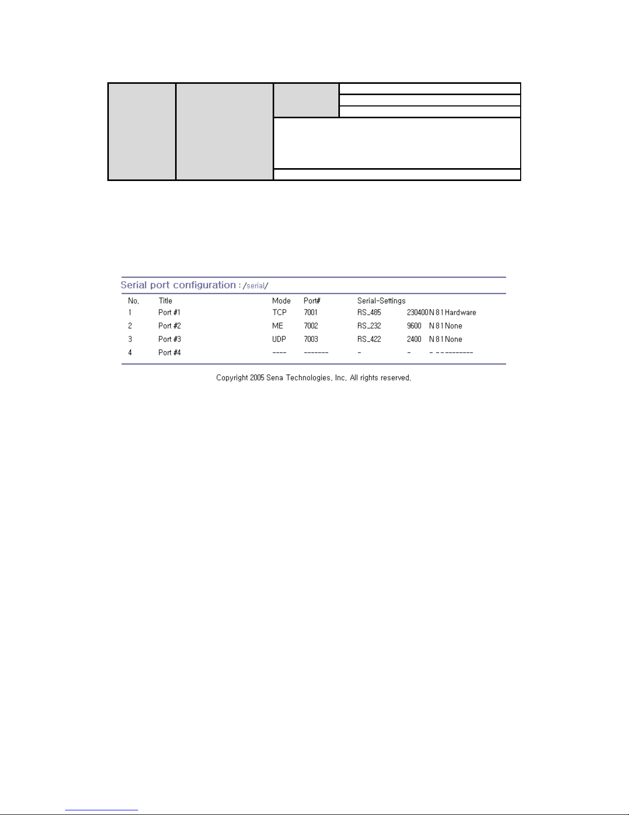
Figure 4-1 shows the web-based serial port configuration screen. This serial port configuration main
screen summarizes port information. In this summary page, user can find which host mode, local port
number and serial port parameters are currently configured.
User can configure port parameters by clicking number or title of corresponding serial port.
Figure 4-1 Serial port configuration main screen
4.2. Serial Port Configuration
Individual Port Configurations of the Pro Series are classified into eight groups:
1. Port enable/disable
2. Port title
3. Host mode
4. Cryptography
5. Serial port parameters
6. Modem configuration
7. Port logging
8. Port event handling
4.2.1. Port Enable/Disable
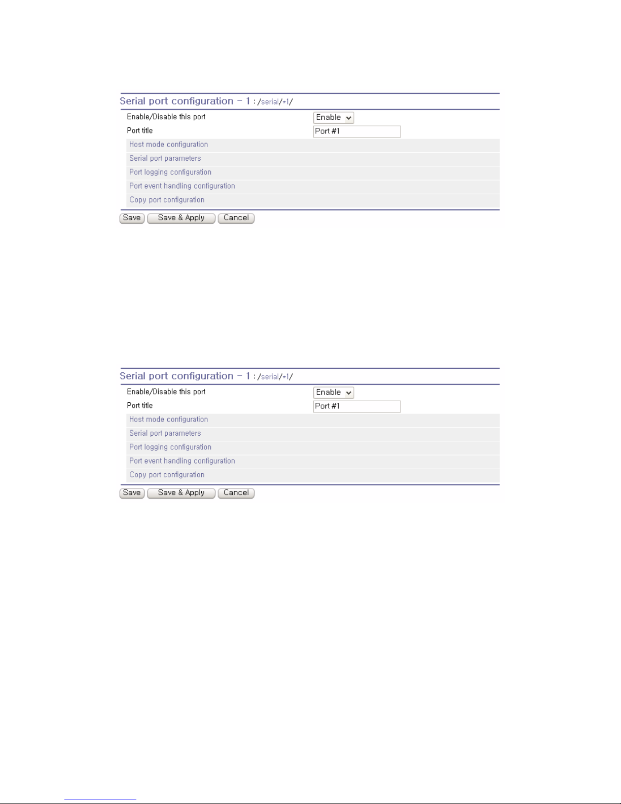
Each serial port can be enabled or disabled. If a serial port is disabled, users cannot access the serial
port. Figure 4-2 shows the serial port enable/disable screen.
Page 42
42
Figure 4-2 Serial port enable/disable
4.2.2. Port Title
Users can enter descriptive information for each port based on the device attached to it. This can
include the device type, vendor, and/or location.
Figure 4-3 Port title configuration
4.2.3. Host Mode Configuration
The Pro Series operating mode is called the “host mode”. Three host modes are available: TCP mode,
UDP mode, Modem emulation mode.
TCP mode
The Pro Series works as both TCP server and client. This mode works for most applications, since it
will transfer the data either from serial port or from TCP port. If there is no connection established on a
TCP port, the TCP port accepts a connection request from any registered remote hosts and relays the
transmitted data to the coupled serial port. If there is any data from the serial port, it connects to the
registered remote hosts and redirects the data.
Page 43
43
UDP mode
The UDP mode operation is similar to that of TCP mode except that it utilizes UDP protocol.
Modem emulation mode
Select this mode when the serial device already supports modem AT commands or users want to
perform the session control by using AT commands. Only TCP session is supported.
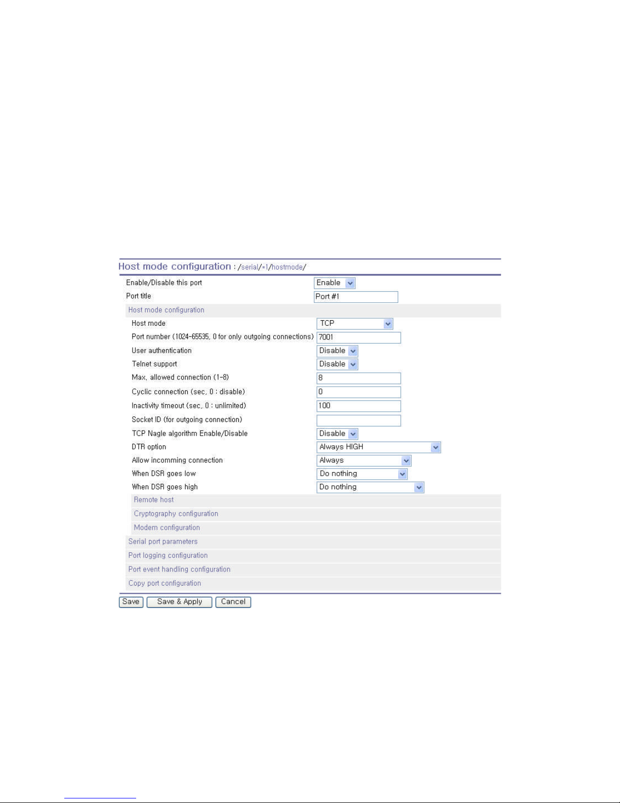
Figure 4-4 shows the main workspace screen for the host mode configuration.
Figure 4-4 Host mode configuration (TCP mode)
4.2.3.1. TCP Mode
For easier understanding of TCP modes, a simplified State Transition Diagram is often used. And to
help users understand the diagram, the TCP state of the Pro Series is briefly described as follows.
[Listen]
Page 44

44
It represents “a waiting for a connection request from any registered remote host”. It is a default startup mode when it is set as TCP mode.
[Closed]
It means “no connection state”. If the data transfer between a remote host and the Pro Series is
completed, the state is changed to this state as a result that either of the remote host or the Pro Series
sent a disconnection request. After this, the state is automatically changed to [Listen] mode.
[Sync-Received]
The state is changed from [Listen] to [Sync-Received] if one of the remote hosts has sent a connection
request. If the Pro Series accepts the request, the state is changed into [Established].
[Sync-Sent]
If the Pro Series has sent a connection request to a remote host, the state is changed from [Closed] to
[Sync-Sent]. This state is maintained until the remote host accepts the connection request.
[Established]
It represents “an open connection”. If one of the hosts, the remote host or the Pro Series, accepts a
connection request from the other, the connection is opened and state is changed into [Established].
[Data]
When it is in [Established] state, data from a host will be transferred to the other one. For easier
understanding of the TCP session operation, we called the state as [Data] state when actual data
transfer is performed. Actually, the [Data] mode is a part of [Established] state as is described in the
RFC 793 [Transmission Control Protocol]. This is a normal state for the data transfer phase of the
connection.
The Pro Series works as either TCP server or client according to the situation. This will be the typical
mode for most applications, since it will transfer the data either from serial port or from TCP port. The
default TCP state is [Listen] which is the same as that of TCP server mode.
1) Typical State Transition
[Listen] --> [Sync-Received] --> [Established] --> [Data] --> [Closed] --> [Listen]
Or
[Listen] --> [Sync-Sent] --> [Established] --> [Data] --> [Closed] --> [Listen]
The initial state is [Listen]. If there are data coming from the serial port, it will connect to the remote
host as a TCP client and then transfer data through the TCP port. If there is incoming connection
request from the remote host, it will accept the connection as a TCP server, and then transfer data
through the serial port. Thus, users can assume that the Pro Series is always connected to the
specified remote host.
Page 45

45
2) Operations
Serial data transfer
Whenever the serial device sends data through the serial port of the Pro Series, data will be
accumulated on the serial port buffer of the Pro Series. If the buffer is full or the time gap reaches the
inter-character timeout (See Options in section 4.2.6. Serial Port Parameters for details on intercharacter timeout), the Pro Series connect to the registered remote host(s). If a TCP session has not
been established yet and the Pro Series succeeds in connecting to the remote host, the data in the
serial port buffer will be transferred to the host. Otherwise, all the data stored in the buffer will be
cleared.
Session disconnection
The connected session will be disconnected when the remote host sends disconnection request or
when no data transfer activity is found through the serial port for certain amount of time, which is
“Inactivity timeout”. All the data remained in the serial port buffer will be cleared when it is
disconnected.
Connection request from remote host
All the incoming TCP connection requests will be rejected in TCP client mode.
3) Parameters
TCP listening port
This is the TCP port number through which a remote host can connect a TCP session, and, send and
receive data. Incoming connection request(s) to the ports other than TCP Listening Port will be
rejected. The Pro Series does restrict the port number from 1024 to 65535 and if it is set as 0 only
outgoing connection is permitted. (TCP server mode)
User authentication
If the User authentication option is enabled, the user can access the port after entering the correct
user ID and password. Please refer to the section 5.9. User Administration for details of user
management.
Telnet protocol
In TCP mode, Pro Series supports Telnet Com Port Control Option (RFC2217 compliant) so that user
can control serial parameters like baud rate, data bits and flow control option using his local RFC2217compliant Telnet client program. (Please refer to section 4.2.6. Serial Port Parameters for more detail
information about serial parameters)
Usually this option is used with the RFC2217-compliant COM port redirector so that user can control
parameters of serial ports of Pro Series using his serial port application program.
Page 46

46
For this purpose, SENA OEM version of Serial/IP from Tactical Software, LLC is bundled with Pro
Series. Please refer to documentations of Serial/IP for more detail information about using the COM
port redirector. (Please refer to section Appendix 5. Using Pro Series With Serial/IP for more detail
information)
Max. allowed connection
The Pro Series supports up to 8 multiple connections from external host(s) to the serial port. If there
are remote host connections by the remote host list configuration already, possible number of
connection will be reduced (Max. allowed connection - remote host(s) connected already). For
example, if user set Max. allowed connection as 8 and if there are 3 connections from Pro Series to
remote hosts, which are configured in the remote host list, then maximum number of connection from
external hosts to a serial port will be reduced to 5. For more detailed information for remote host list
configuration, please refer to 4.2.4. Remote Host Configuration section.
Cyclic Connection
If Cyclic Connection function is enabled, the Pro Series will make an attempt to connect to the userdefined remote host(s) at a given interval even if there’s no incoming serial data from the device
connected to that serial port. If there is data on the remote host(s) to be sent to serial device, it can be
transferred to the serial device via Pro Series’ serial port after the connection is established. Eventually,
users can monitor the serial device periodically by making the remote host send the serial command
to the Pro Series whenever it is connected to the remote host. This option is useful when users need
to gather the device information periodically even if the serial device does not send its data periodically.
Figure 4-5 shows the State Transition Diagram of the session operations in TCP mode.
Inactivity Timeout
When Inactivity Timeout function is enabled, connection between remote host(s) and Pro Series will
be closed automatically if there is no data transmission during the value which is set in Inactivity
Timeout configuration.
Socket ID
When many Pro Series devices connect a same remote host(s), sometimes it is needed to identify the
device. In this case, Socket ID is available for identification of each device. Pro Series send the Socket
ID string before starting the data transmission. User can define Socket ID with a specific string. In TCP
mode, specified Socket ID strings are sent once at the time of establishing TCP connection.
TCP Nagle algorithm
Modern TCP implementations include a mechanism, known as the Nagle algorithm, which prevents
the unnecessary transmission of a large number of small packets. This algorithm has proved useful in
Page 47

47
protecting the Internet against excessive packet loads. However, some applications suffer
performance problems as a result of the traditional implementation of the Nagle algorithm.(An
interaction between the Nagle algorithm and TCP’s delayed acknowledgement policy can create
especially severe problems, through a temporary “deadlock.”) TCP Nagle algorithm can be disabled or
enabled through this option.
DTR/DSR behavior
Purpose of the DTR/DSR pin is to control TCP connection state by using serial port signal. The DTR is
a write-only output signal, whereas the DSR is a read-only input signal in the Pro Series.
The DTR option can be set to one of three options:
Always HIGH: The state of the DTR pin is maintained high.
Always LOW: The state of the DTR pin is maintained low.
High when TCP/UDP is opened: The state of the DTR pin will be maintained high if the TCP
connection is established.
The Allow incoming connection can be set to one of two options:
Always: Incoming connection from remote host is always allowed.
Only when DSR is high: Incoming TCP connection from remote host is allowed only when the
state of DSR pin is high.
The When DSR goes low can be set to one of two options:
Do nothing: Nothing is done when the state of DSR pin becomes low from high.
Close all connections: All the TCP connections are closed when the state of DSR pin becomes
low from high.
The When DSR goes high can be set to one of three options:
Do nothing: Nothing is done when the state of DSR pin becomes high from low.
Try to connect continuously: Pro Series continuously tries to establish the connection to remote
host when the state of DSR pin becomes high from low.
Try to connect once: Pro Series only once tries to establish the connection to remote host when
the state of DSR pin becomes high from low.
Note:
1. DTR/DSR behavior configuration will not be effective when the modem is enabled.
2. DTR/DSR behavior is not effective in RS422 and RS485 mode.
Page 48
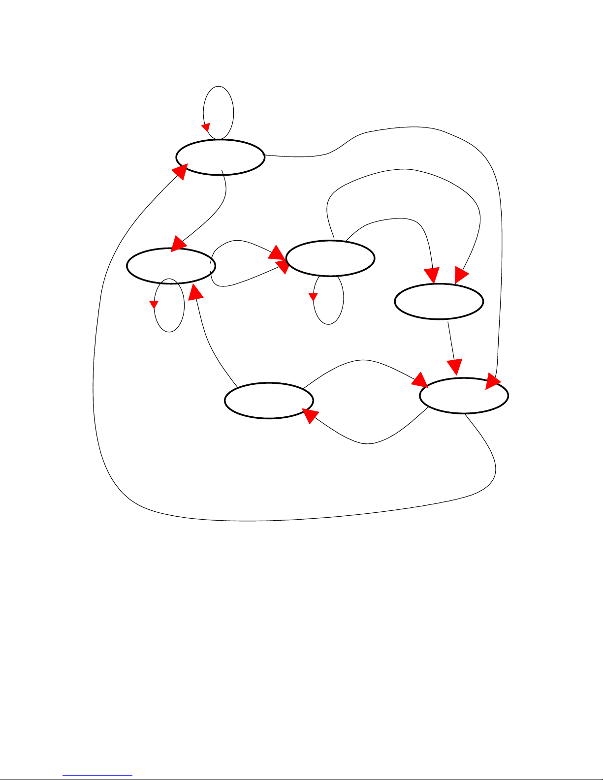
48
Established
Inactivity time-out
TCP connection request rejected
Or internal TCP time-out
TCP connection request accepted
Sync-Sent
Incoming data via serial port
Incoming data
from remote host
In-coming TCP Close request
Listen
Incoming TCP connection request
Incoming data via serial port
Sync-Recvd
Reject
Accept
Closed
Data
Figure 4-5 State Transition Diagram of TCP mode
4.2.3.2. UDP Mode
The UDP mode operation is similar to that of TCP mode except that it is based on UDP protocol and
only one pre-defined remote host is able to communicate with the Pro Series. Users do not have to
configure cyclic connection, since UDP is a connectionless protocol.
Page 49
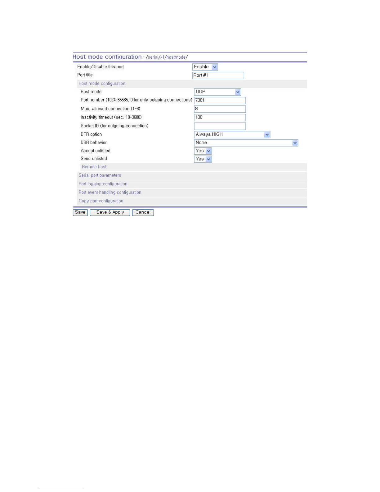
49
Figure 4-6 Host mode configuration (UDP mode)
1) Operations
If a remote host sends a UDP datagram to the one of UDP Local port of the Pro Series, Pro Series first
checks whether it is from one of the hosts configured on remote host configuration. If the remote host
is one of the hosts configured on remote host configuration, then Pro Series transfers the data through
the serial port. Otherwise, the Pro Series discards the incoming UDP datagram. But user can force Pro
Series accept all incoming UDP datagram regardless remote host configuration by setting Accept UDP
datagram from unlisted remote host parameter as ‘Yes’. If there is any incoming data from the serial
port, the Pro Series transfers the data to the remote host defined on remote host configuration. If the
remote port is not opened, the Pro Series will not transfer the data.
2) Parameters
UDP receiving port
The concept is the same as TCP listening port. See parameters in the section 4.2.3.1. TCP Mode for
details.
Max. allowed connection
The concept is the same as that of TCP communication. See parameters in the section 4.2.3.1. TCP
Mode for details.
Page 50

50
Inactivity Timeout
In UDP mode, Inactivity Timeout is used in maintaining recent unlisted remote host. If there is no data
transmission between unlisted remote host and serial port of Pro Series during Inactivity Timeout, Pro
Series will not send data from a serial port to the recent unlisted remote host again. Namely, Inactivity
Timeout in UDP mode is the time maintained recent unlisted remote host list by Pro Series.
Note: If user set Inactivity Timeout as 0 in UDP mode, Pro Series does not allow any new connection
from/to remote host if the number of current remote host exceeds Max. allowed connections.
Socket ID
When many Pro Series devices connect a same remote host(s), sometimes it is needed to identify the
device. In this case, Socket ID is available for identification of each device. Pro Series send the Socket
ID string before starting the data transmission. User can define Socket ID with a specific string. In UDP
mode, specified Socket ID strings are added to the head of every packet.
DTR/DSR behavior
Purpose of the DTR/DSR pin is to control UDP connection state by using serial port signal. The DTR is
a write-only output signal, whereas the DSR is a read-only input signal in the Pro Series.
The DTR option can be set to one of three options:
Always HIGH: The state of the DTR pin is maintained high.
Always LOW: The state of the DTR pin is maintained low.
High when TCP/UDP is opened: The state of the DTR pin will be maintained high if the UDP
connection is established.
The DSR behavior can be set to one of two options:
None: Incoming connection from remote host is always allowed and nothing is done even though
the state of DSR pin changes.
Allow TCP/UDP connection only by HIGH: Pro Series receives UDP data from the remote host
only when the DSR status is high.
Note:
1. DTR/DSR behavior is not effective in RS422 and RS485 mode.
Accept UDP datagram from unlisted remote host
If Accept unlisted (Accept UDP datagram from unlisted remote host) function is set as ‘No’, Pro Series
will accept only incoming UDP datagram from the remote host(s) configured on remote host
configuration. On the contrary if Accept unlisted function is set as ‘Yes’, Pro Series will accept all
incoming UDP datagram regardless remote host configuration.
Send to recent unlisted remote host
If Send unlisted (Send to recent unlisted remote host) function is set as ‘Yes’, Pro Series sends data to
Page 51

51
the remote host, which has connected Pro Series recently. Recent unlisted remote host is a remote
host, which has accessed a corresponding serial port of Pro Series but is not configured on remote
host configuration. Surely, Pro Series also send data to the hosts, which are configured on remote
host configuration. If Send unlisted function is set as ‘No’, Pro Series sends data only to the host(s)
which are configured on remote host configuration. Pro Series maintains a recent unlisted remote host
during the Inactivity Timeout.
4.2.3.3. Modem Emulation Mode
1) Operations
In modem emulation mode, the serial port process acts as if it is a modem attached to the serial
device. It accepts AT modem commands and answers to them, as modems would do. It also handles
the modem signals correctly. Modem emulation mode is useful in the following cases.
There already exists a modem attached to the users’ serial device.
If users’ serial device already has a modem for phone-line connection, it can be just replaced by the
Pro Series for Ethernet connection. What users need to do is to use an IP address (or domain name)
and port number instead of phone number as a parameter of ATA/ATDT commands.
It is required to send serial data to the multiple remote hosts.
If the serial device should send data to the multiple hosts, modem emulation mode is required. For
example, the first data from the serial device can be sent to the first data acquisition server and the
second to the second server. What user device has to do is to change the IP address (or domain
name) and port number parameters whenever the device sends ATD(T) XXX command.
By using the modem emulation mode of the Pro Series, users can have their serial device connected
to the Ethernet network easily, which is cheaper than using phone line modem. Table 4-2 is a
summarized AT command table which is supported by the Pro Series. Figure 4-7 shows the typical
case of the serial port command flow when ATDAcommand is used to connect to the Ethernet network.
Table 4-2 AT commands supported in the Pro Series
Command Internal Operation Response
4
(Verbose Code)
+++ Return to command input mode None
4
If Echo mode is enabled, the command will be sent back first. And then, corresponding response will be sent. If disabled, only
response will be sent.
Page 52

52
ATD(T)
[remote IP or domain
name]:[remote
port][CR][LF]
or
ATD(T)
[remote IP][remote port]
[CR][LF]
Set TCP mode as TCP client mode. And then, try to connect
to the specified remote host.
e.g. atdt192.168.1.9:1002
e.g. atdt1921680010091002
Connect to IP address, 192.168.1.9, port 1002
(Port Number is permitted from 1 to 65534)
e.g. atdtps.sena.com:1002
Connect to domain address ps.sena.com, port 1002
ATDR
[remote IP or domain
name]:[remote port]
[CR][LF]
This command is similar to ATD(T). The difference is that
ATDR forces the connection to be Raw TCP connection
regardless of Cryptography configuration and Default Data
mode option.
ATDS
[remote IP or domain
name]:[remote port]
[CR][LF]
This command is similar to ATD(T). The difference is that
ATDR forces the connection to be SSLv3 connection. The
Cryptography configuration should be SSLv3. If not, this
command returns ERROR.
If success,
CONNECT [CR][LF]
If failure in connection,
NO CARRIER [CR][LF]
If other errors,
ERROR [CR][LF]
AT&Tn [CR][LF]
Change and display the default data mode.
AT&T : Display the current Default data mode
AT&T0 : Change the Default data mode to Raw TCP mode
AT&T1 : Change the Default data mode to Telnet binary mode
AT&T
If Data mode=RawTCP
0 [CR][LF]
If Data mode=Telnet
binary
1 [CR][LF]
AT&Tn
If success,
OK[CR][LF]
If failure,
ERROR[CR][LF]
AT or ATZ [CR][LF] Initialize TCP socket and serial port
ATA/ [CR][LF] Repeat last command
ATA
[Local port number]
[CR][LF]
Set TCP mode as TCP server mode. And then, set TCP state
as [Listen].
-. If the command parameter, Local port number is not
specified, the TCP session parameter, Local Port is used
instead.
ATAR
[Local port number]
[CR][LF]
This command is similar to ATA. The difference is that ATAR
forces the connection to be Raw TCP connection regardless
of Cryptography configuration and Default Data mode option.
ATAS
[Local port number]
[CR][LF]
This command is similar to ATA. The difference is that ATAS
forces the connection to be SSLv3 connection. The
Cryptography configuration should be SSLv3. If not, this
command returns ERROR.
ATEn [CR][LF]
E, E0: Disable echo
E1: Enable echo
ATOn [CR][LF] O, O0: Turn to data mode
ATQn [CR][LF]
Q, Q0: Response display on (default)
Q1: Response display off
ATVn [CR][LF]
V, V0: Response = <numeric code> [CR][LF]
V1 (default): Response = <verbose code> [CR][LF]
AT&Fn [CR][LF] F, F0, F1: Restore default modem settings
ATHn [CR][LF]
H, H0: Disconnect current TCP connection
All the data will be cleared
H1: Keep the current TCP connection
If success,
OK [CR][LF]
If failure,
ERROR [CR][LF]
Page 53

53
ATIn [CR][LF]
I, I0 : display “Sena Technologies, Inc.”
I3 : display model number
Others : display “OK”
<=
AT\Tn [CR][LF]
Set inactivity timer to n minutes
\T, \T0: inactivity timer disabled (default)
ERROR [CR][LF]
or
OK [CR][LF]
ATBn, ATCn, ATLn, ATMn,
ATNn, ATP, ATT, ATYn,
AT%Cn, AT%En, AT&Bn,
AT&Gn, AT&In, AT&Qn,
AT&V,ATMn, AT\An,
AT\Bn, AT\Nn, ATXn
None OK [CR][LF]
ATS?, ATSn=x
Internal S-register can be set or read.
Default values are shown on Table4-4
Changed values are not preserved if the power is off.
<=
AT&Cn, AT&Wn, AT&Zn=x
Factory default response is ERROR.
This can be changed to OK by user configuration.
(Figure 4-8)
ERROR [CR][LF]
or
OK [CR][LF]
ATFn [CR][LF] None
If n=1 OK [CR][LF]
Else ERROR [CR][LF]
ATWn None
If n=0 OK [CR][LF]
Else ERROR [CR][LF]
AT+DATE
Set the system data and time
e.g. AT+DATE=2007.01.01-14:30:30
AT+NET
Set (or Display) the IP address and the subnet mask.
e.g. AT+NET=192.168.17.9/255.255.0.0
AT+GATEWAY
(AT+GW)
Set(or Display) the default gateway
e.g. AT+GATEWAY=192.168.1.1
AT+DNS
Set(or Display) the domain name server.
e.g. AT+DNS=168.126.63.1/168.126.63.2
AT+NETINFO *
(AT+NI)
Display IP configurations (IP address, subnet mask, mode,
gateway, dns)
e.g. AT+NETINFO
=> ip mode : dhcp
ip address : 192.168.231.10
subnetmask : 255.255.0.0
gateway : 192.168.1.1
primary dns : 168.126.63.1
If success,
OK [CR][LF]
If failure,
ERROR [CR][LF]
* Not supported in PS810
Table 4-3 AT commands Response Code
Verbose Code
(After “ATV1” command executed)
Non-Verbose Code(Numeric Code)
(After “ATV0” command executed)
Description
OK 0 Command executed
CONNECT 1 Modem connected to line
RING 2 A ring signal has been detected
NO CARRIER 3 Modem lost carrier signal
ERROR 4 Invalid command
Page 54
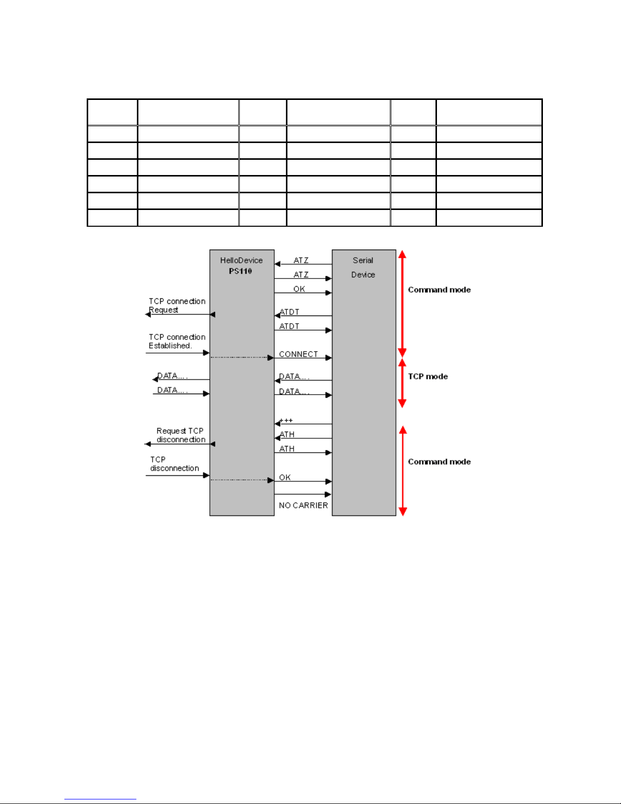
54
Table 4-4 Default value of S-Registers
Index Default Value Index Default Value Index Default Value
0 ~ 1 0 2 43 3 13
4 10 5 8 6 2
7 30 8 2 9 6
10 14 11 100 12 50
13 ~ 24 0 24 5 25 1
26 ~ 37 0 38 20 39 ~ 99 0
Figure 4-7 Typical case of command/data flow of modem emulation mode
In modem emulation mode, user can also set specific phone number to host address/port mapping
table. If user set the phone number to host address/port mapping table as shown on Figure 4-8, Pro
Series will try to connect to port 7001 of 192.168.1.1 host by the ‘atdt5737772’ command in modem
emulation mode.
2) Parameters
DTR/DSR behavior
Purpose of the DTR/DSR pin is to control TCP/UDP connection state by using serial port signal. The
DTR is a write-only output signal, whereas the DSR is a read-only input signal in the Pro Series.
Page 55

55
The DTR option can be set to one of three options:
Always HIGH: The state of the DTR pin is maintained high.
Always LOW: The state of the DTR pin is maintained low.
High when TCP/UDP is opened: The state of the DTR pin will be maintained high if the UDP
connection is established.
The DSR behavior can be set to one of two options:
None: Incoming connection from remote host is always allowed and nothing is done even though
the state of DSR pin changes.
Allow TCP/UDP connection only by HIGH: Pro Series allows incoming TCP connection from
remote host and receives UDP data from the remote host only when the DSR status is high.
However, the connection to the remote host will be disconnected when the DSR status is changed
from high to low regardless of the value of DSR behavior.
Note:
1. DTR/DSR behavior is not effective in RS422 and RS485 mode.
Phone number to host address mapping table
In modem emulation mode, user can set a specific phone number to host address/port mapping table.
If user set the phone number to host address/port mapping table as shown on Figure 4-8, Pro Series
will try to connect to port 6001 of 192.168.0.100 host by the ‘atdt25737772’ command in modem
emulation mode.
CONNECT string in non-verbose mode (ATV0) and CONNECT string in verbose mode
(ATV1)
In modem emulation mode, the Pro Series responds to the AT command according to result code in
Table 4-3 by default. But there are some cases that device requires different form of response code
for remote host connection. For example, when the Pro Series connects the remote host, it replies
“1”(if ATV0 command is set) or “CONNECT” (if ATV1 command is set) result code by default. But if
user needs “12” (if ATV0 command is set) or “CONNECT 9600” (if ATV1 command is set) response
for this case, he can get the required result after setting CONNECT strings as shown on Figure 4-8.
Respond to AT&Cn, AT&Wn and AT&Zn with
For the following three AT commands such as
AT&Cn, AT&Wn and AT&Zn
user can select the response as one of OK or ERROR.
Command echo delay(ms)
AT commands that are entered by user can be echoed with a delay specified in this menu.
This is useful if user uses modem emulation mode in RS485 mode.
Page 56
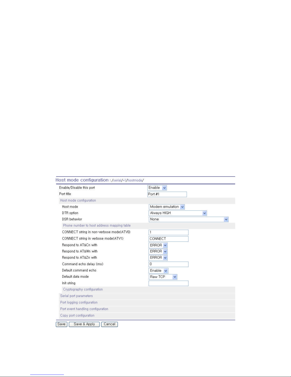
56
Default command echo
User can disable or enable echo of AT command that is entered by user in this menu.
(Same functionality to ATEn command)
Default data mode
User can select the TCP data mode between Raw TCP mode and Telnet binary mode. The Raw TCP
means that there is no application protocol over the TCP protocol. The Telnet binary mode means that
there is Telnet protocol over the TCP protocol. The Telnet binary mode supports the Telnet COM Port
Control Option defined by RFC2217. When selecting this option with a COM Port Redirector
compatible with RFC2217, user is able to control the serial port parameter of the Pro Series through a
serial port application such as Hyperterminal.
Init string
User can specify the first AT command for Pro Series to execute when Pro Series starts in Modem
Emulation mode for the first time as the result of rebooting or applying changes.
Figure 4-8 Host mode configuration (Modem emulation mode)
Page 57
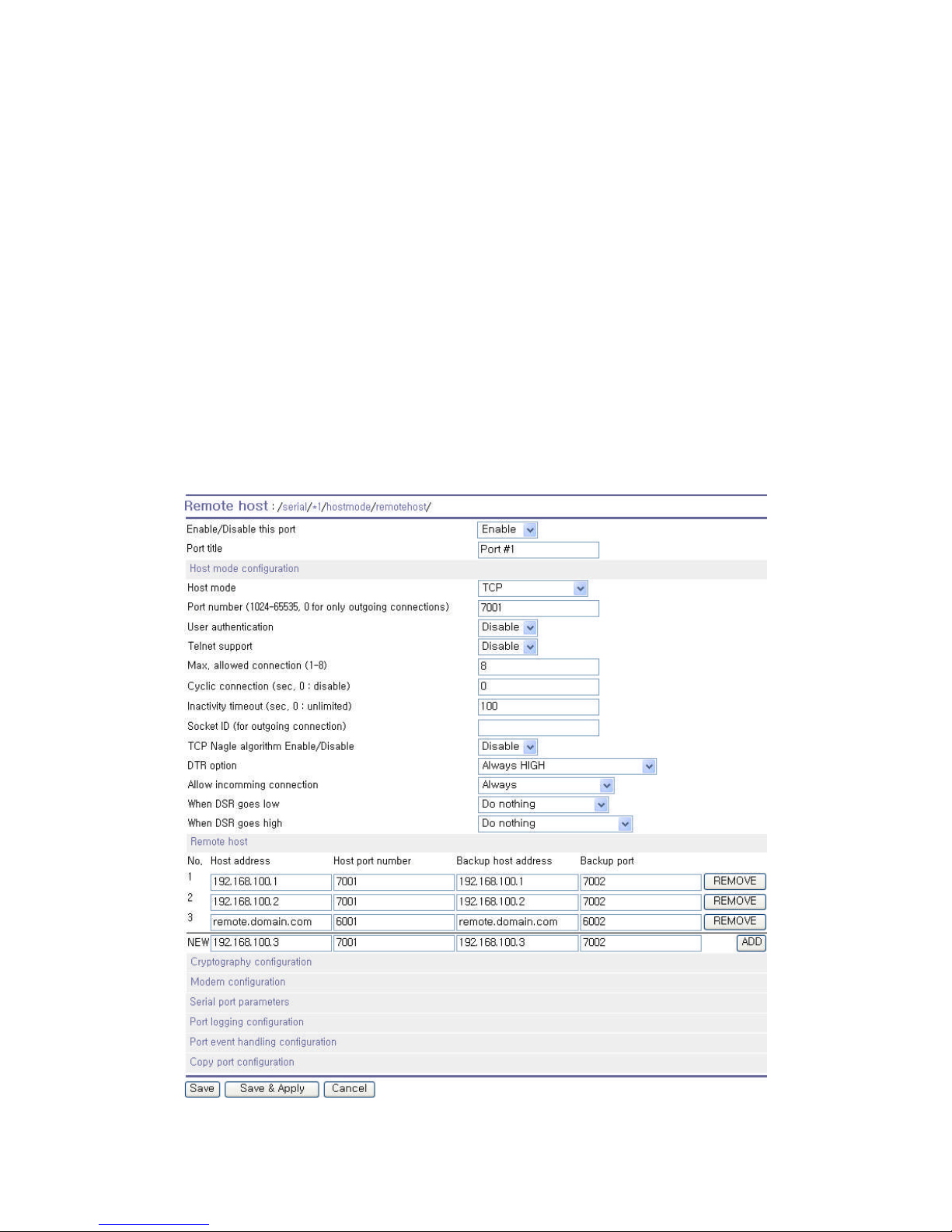
57
4.2.4. Remote Host Configuration
Remote host configuration is the list of hosts that will receive data from serial port of Pro Series when
there is data transmission from the serial port of the Pro Series.
In TCP mode, user can also configure secondary remote host (Backup host) that will receive data from
serial port if Pro Series fails to connect to primary remote host. If a connection to the primary remote
host can be made, Pro Series dose not send data to secondary remote host until connection to
primary remote host failed. And the maximum possible number of primary remote host is limited up to
4 remote connections.
In UDP mode, user can only configure a primary remote host because there is no way for Pro Series
to check status of primary remote host, so secondary remote host is meaningless.
The maximum number of remote host is limited up to 4 in the Pro Series. Figure 4-9 shows Remote
host configuration pages of the Web UI. (TCP mode)
User can also set any effective domain name as Host IP address in the Remote host configuration.
Figure 4-9 Remote host configuration
Page 58
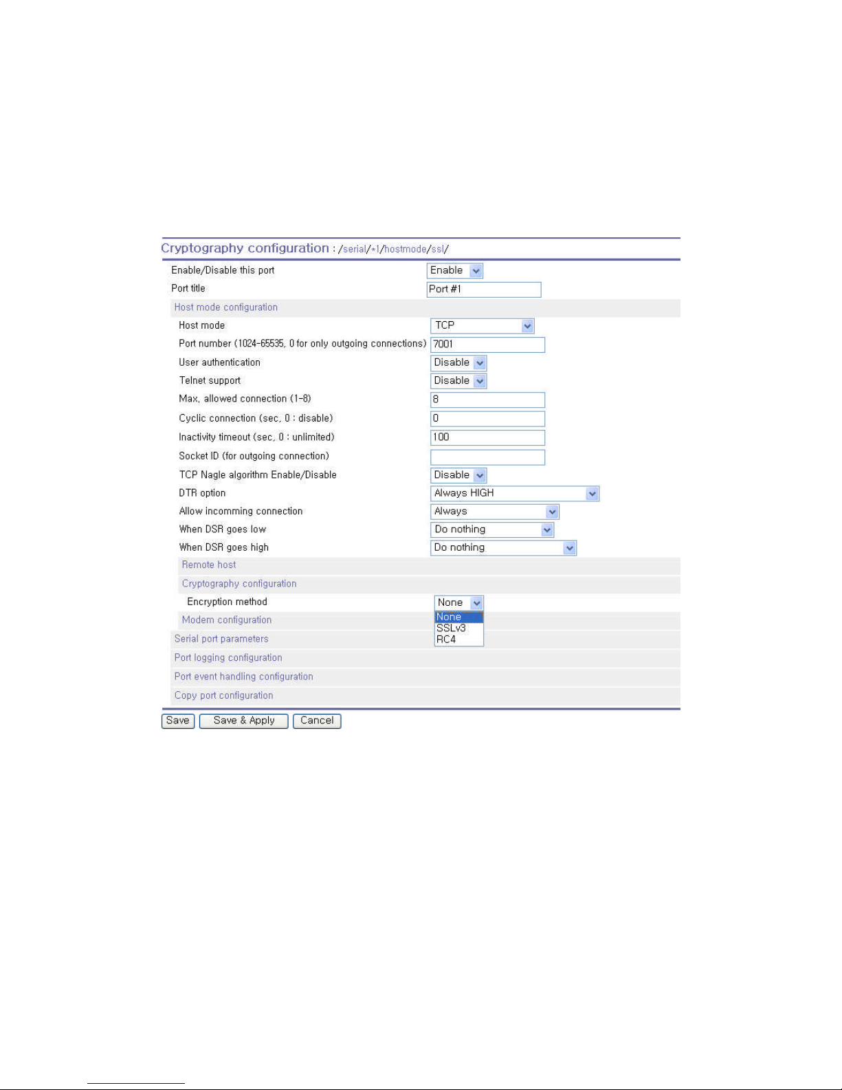
58
4.2.5. Cryptography Configuration
The Pro Series supports encrypted sessions for only the TCP mode including modem emulation mode
(not UDP mode).
Figure 4-10 Cryptography configuration
4.2.5.1. Secure Sockets Layer(SSL) Cryptography Method
By setting the cryptography method as SSL, the Pro Series can communicate with another device
supporting SSLv3 cryptography method during encrypted sessions.
SSL was developed by Netscape for use between clients and servers. SSL layers on top of any
transport protocol and can run under application protocols such as HTTP. SSL aims to be secure, fast,
and adaptable to other Web protocols. SSL provides data security for applications that communicate
across networks. SSL is a transport-layer security protocol layered between application protocols and
TCP/IP.
Page 59

59
To initiate SSL sessions, exchange of messages called the SSL handshake is required between two
devices (Server and Client). The SSL protocol uses a combination of public-key and symmetric key
encryption. Symmetric key encryption is much faster than public-key encryption, but public-key
encryption provides better authentication techniques. The handshake allows the server to authenticate
itself to the client using public-key techniques, and then allows the client and the server to cooperate in
the creation of symmetric keys used for rapid encryption, decryption, and tamper detection during the
session that follows. The details of handshake process step involved can be summarized as follows:
1. The client sends the server the client’s SSL version number, cipher settings, randomly
generated data, and other information the server needs to communicate with the client using
SSL.
2. The server sends the client the server’s SSL version number, cipher settings, randomly
generated data, and other information the client needs to communicate with the server over
SSL. The server also sends its own certificate and, if the client is requesting a server resource
that requires client authentication, requests the client’s certificate.
3. The client uses some of the information sent by the server to authenticate the server. If the
server cannot be authenticated, the user is warned of the problem and informed that an
encrypted and authenticated connection cannot be established. If the server can be
successfully authenticated, the client goes on to next step.
4. Using all data generated in the handshake so far, the client (with the cooperation of the server,
depending on the cipher being used) creates the premaster secret for the session, encrypts it
with the server’s public-key (obtained from the server’s certificate, sent in step 2), and sends
the encrypted premaster secret to the server. SSL differ in the way this “shared” master secret
is created
5. If the server has requested client authentication (an optional step in the handshake), the client
also signs another piece of data that is unique to this handshake and known by both the client
and server. In this case the client sends both the signed data and the client’s own certificate to
the server along with the encrypted premaster secret.
6. If the server has requested client authentication, the server attempts to authenticate the client.
If the client cannot be authenticated, the session is terminated. if the client can be successfully
authenticated, the server uses its private key to decrypt the premaster secret, then performs a
series of steps (which the client also performs, starting from the same premaster secret) to
generate the master secret.
7. Both the client and the server use the master secret to generate the session keys, which are
symmetric keys used to encrypt and decrypt information exchanged during the SSL/TLS
session and to verify its integrity - that is, to detect any changes in the data between the time it
was sent and the time it is received over the SSL connection.
8. The client sends a message to the server informing it that future messages from the client will
Page 60
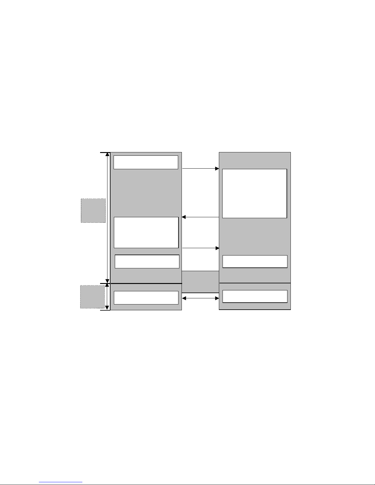
60
be encrypted with the session key. It then sends a separate (encrypted) message indicating
that the client portion of the handshake is finished.
9. The server sends a message to the client informing it that future messages from the server will
be encrypted with the session key. It then sends a separate (encrypted) message indicating
that the server portion of the handshake is finished.
10. The SSL handshake is now complete, and the SSL session has begun. The client and the
server use the session keys to encrypt and decrypt the data they send to each other and to
validate its integrity.
Client
Client Hello
Certificate
ClientKeyExchange
CertificateVerify
Application Data
ChangeCiperSpec
Server Hello
Certificate
ServerKeyExchange
CertificateRequest
ServerHelloDone
ChangeCiperSpec
Application Data
Handshake
Finished
Plain
Text
Cipher
Text
Server
Figure 4-11 Typical SSL Handshake Process
The Pro Series can act as a SSL server or as a SSL client depending on status of TCP mode. If TCP
connection with SSL is initiated from remote host first, Pro Series acts as a SSL server during the SSL
handshake process. On the contrary, if TCP connection with SSL is initiated from serial port of Pro
Series first, Pro Series acts as a SSL client during the SSL handshake process.
Client Authentication by certificate (server mode only)
If user selects Client Authentication by certificate option as “Enable”, Pro Series will request the client’s
certificate while in SSL handshaking process (Step 2). On the contrary, if user selects Client
Authentication by certificate option as “Disable”, Pro Series does not request the client’s certificate
while in SSL handshaking process (Step 2).
Page 61
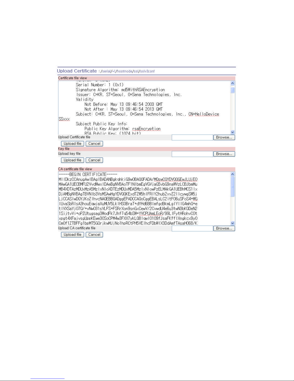
61
4.2.5.1.1 Upload Certificate
Figure 4-12 Upload certificate
User is able to upload Certificate, Certificate Authority certificate, Private key. The Certificate,
Certificate Authority certificate, Private key should be in PEM format.
4.2.5.2. RC4 Cryptography Method
In RC4 cryptography mode, the Pro Series encrypt and decrypt all TCP streams using a Key string.
The Pro Series can communicate with another device or another Pro Series that supports RC4
cryptography mode with same Key string.
For the sample application programs of SSL/RC4 cryptography method, please contact the Sena
Technical support.
Page 62
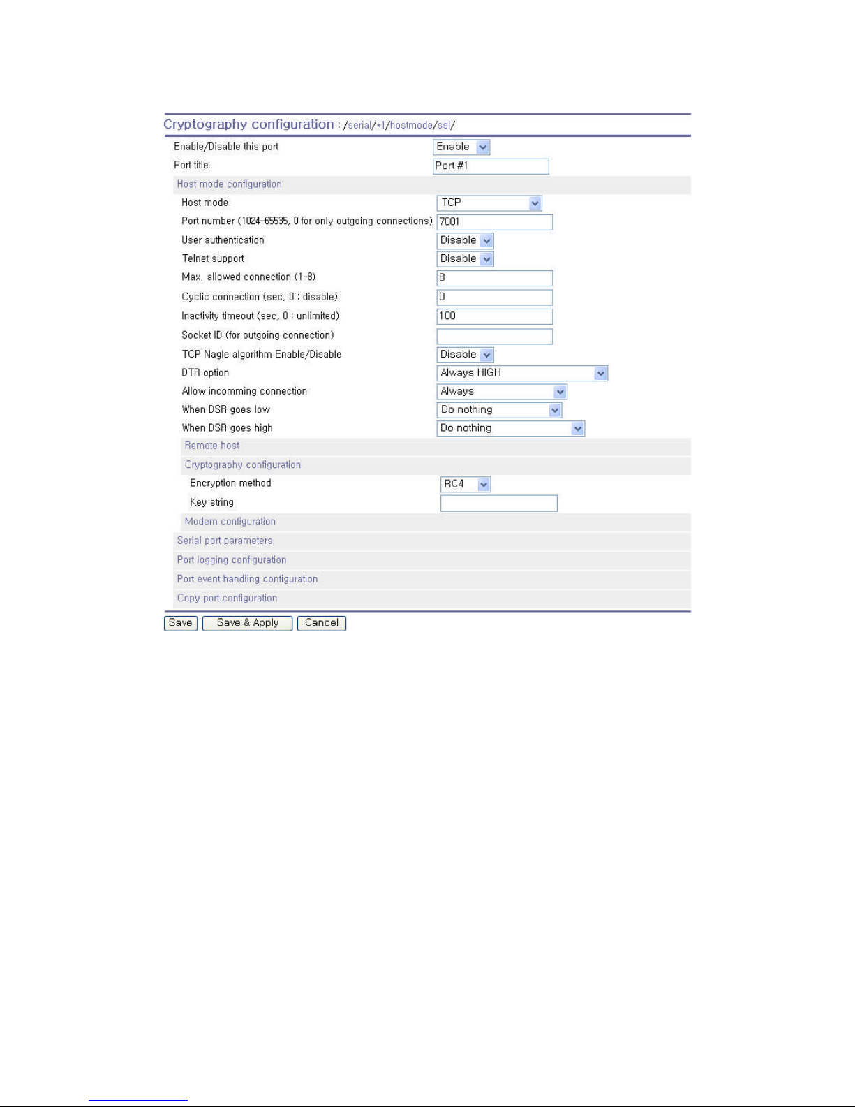
62
Figure 4-13 RC4 Cryptography configuration
4.2.6. Serial Port Parameters
To connect the serial device to the Pro Series serial port, the serial port parameters of the Pro Series
should match exactly to that of the serial device attached. The serial port parameters are required to
match this serial communication. The parameters required for the serial communication are: UART
type, baud rate, data bits, parity, stop bits, flow control and inter-character timeout.
UART type
First of all, the Pro Series and the serial device must agree on the serial communication type, which is
one of RS232 mode, RS422(RS485 full) mode or RS485 half mode. User can set the serial
communication type by using DIP switch near by serial port in case of PS110/410. To change the
serial communication type, change the position of each DIP switch as shown on Figure 4-14. For
PS810, user can change the serial communication type of each serial port using configuration menu
as shown on Figure 4-17.
Page 63
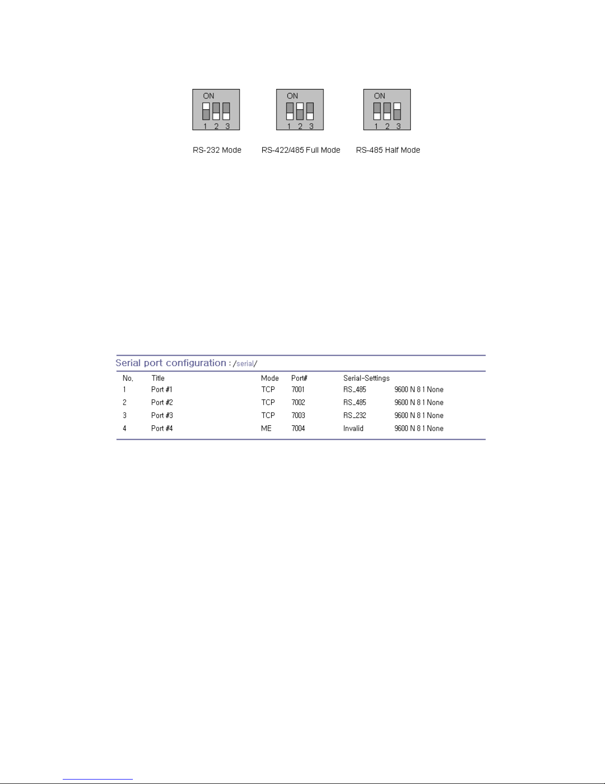
63
Figure 4-14 Serial communication type and DIP switch configuration. (PS110/410)
For more information about pin out of serial port and wiring diagram, please refer to Appendix 1.
Connections section.
Note:
1. Please turn off the power of the Pro Series device before changing the position of DIP switch in
case of PS110/410. Changing the position of DIP switch while the power is on may cause
damage to the device.
(If the DIP switches are set incorrectly, the PS110/410 will display “Invalid” for the UART type on
the UI as shown on Figure 4-15, which will hinder communications to the serial port.)
2. In case of PS810, UART type can be changed by software through configuration only. So
PS810 does not have a DIP switch for changing UART type.
Figure 4-15 Invalid UART type settings displayed on the Serial port configuration main screen
Baud rate
The valid baud rate for the Pro Series is as follows:
75, 150, 200, 300, 600, 1200, 2400, 4800, 9600, 19200, 38400, 57600, 115200, and 230400
The factory default setting is 9600.
Data bits
Data bits can be between 7 bits and 8 bits. The factory default setting is 8 bits.
Parity
Parity can be none, even or odd. The factory default setting is none.
Stop bits
Stop bits can be between 1 bit and 2 bits. The factory default setting is 1 bit.
Page 64
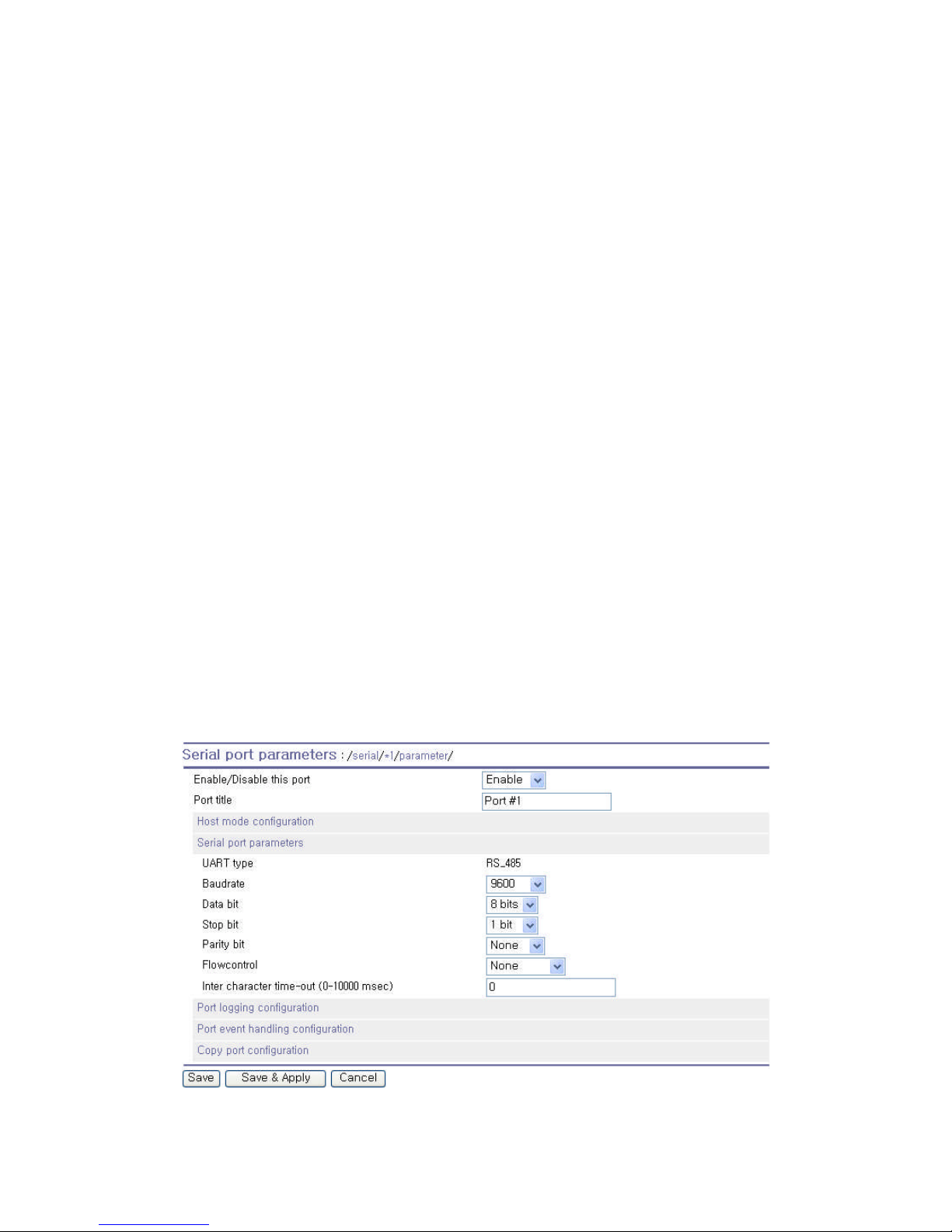
64
Flow control
The factory default setting of the flow control is None. Software Flow Control using XON/XOFF and
hardware flow control using RTS/CTS are supported by the Pro Series.
Software flow control method controls data communication flow by sending special characters
XON/XOFF (0x11/0x13) between two connected devices. And hardware flow control method controls
data communication flow by sending signals back and forth between two connected devices.
Note: Flow control is supported only in RS232 and RS422 mode. RS485 mode does not support any
kind of flow control method.
Inter-character timeout
This parameter defines the interval the Pro Series fetches the overall serial data from its internal buffer.
If there is an incoming data through the serial port, the Pro Series stores data into the internal buffer.
The Pro Series transfers data stored in the buffer via TCP/IP, only if the internal buffer is full or if the
inter-character time interval reaches the time specified in the inter-character timeout setting. If inter-
character timeout is set as 0, then data stored in the internal buffer will be transferred immediately
without any delay.
Optimal inter-character timeout would be different according to your application but at least it must be
larger than one character interval within specified baud rate. For example, assume that the serial port
is set to 1200 bps, 8 Data bits, 1 stop bit, and no parity. In this case, the total number of bits to send a
character is 10 bits and the time required to transfer one character is
10 (bits) / 1200 (bits/s) * 1000 (ms/s) = 8.3 ms.
Therefore, you have to set inter-character timeout to be larger than 8.3 ms. The inter-character
timeout is specified in milliseconds.
Figure 4-16 Serial parameter configuration (PS110/410)
Page 65
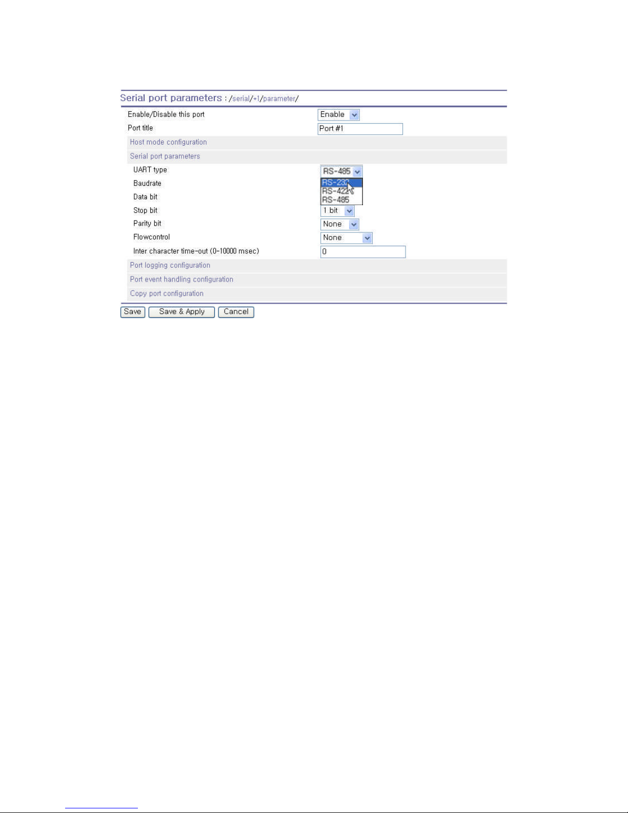
65
Figure 4-17 Serial parameter configuration (PS810)
4.2.7. Modem Configuration
The Pro Series supports direct modem connection to the serial port. When user wants to connect to a
modem on its serial port, he must configure Modem init-string and DCD behavior on the modem
configuration page. The Pro Series supports modem connection only when host mode is set as TCP
mode.
Enable/Disable modem
By enabling this menu, user can attach a modem directly to the serial port of Pro Series. If this
parameter is enabled, Pro Series considers this port will be used for modem use exclusively.
Modem init-string
User can specify modem initialization string for his modem in Modem init-string parameter. When a
serial port is set to modem mode by setting Enable/Disable modem parameter as Enabled, Pro Series
sends modem initialization string to the serial port whenever rising edge of DTR pin is detected or
parameter related with serial port configuration is changed.
DCD behavior
If DCD behavior is set as Allow TCP connection only by HIGH, Pro Series permits a connection from
the remote host only when the DCD status of serial port is high. This feature is useful when user want
to use a serial port only for dial-in modem mode. In this case, if there is no connection through modem
already, Pro Series will not permit a TCP side connection.
Page 66
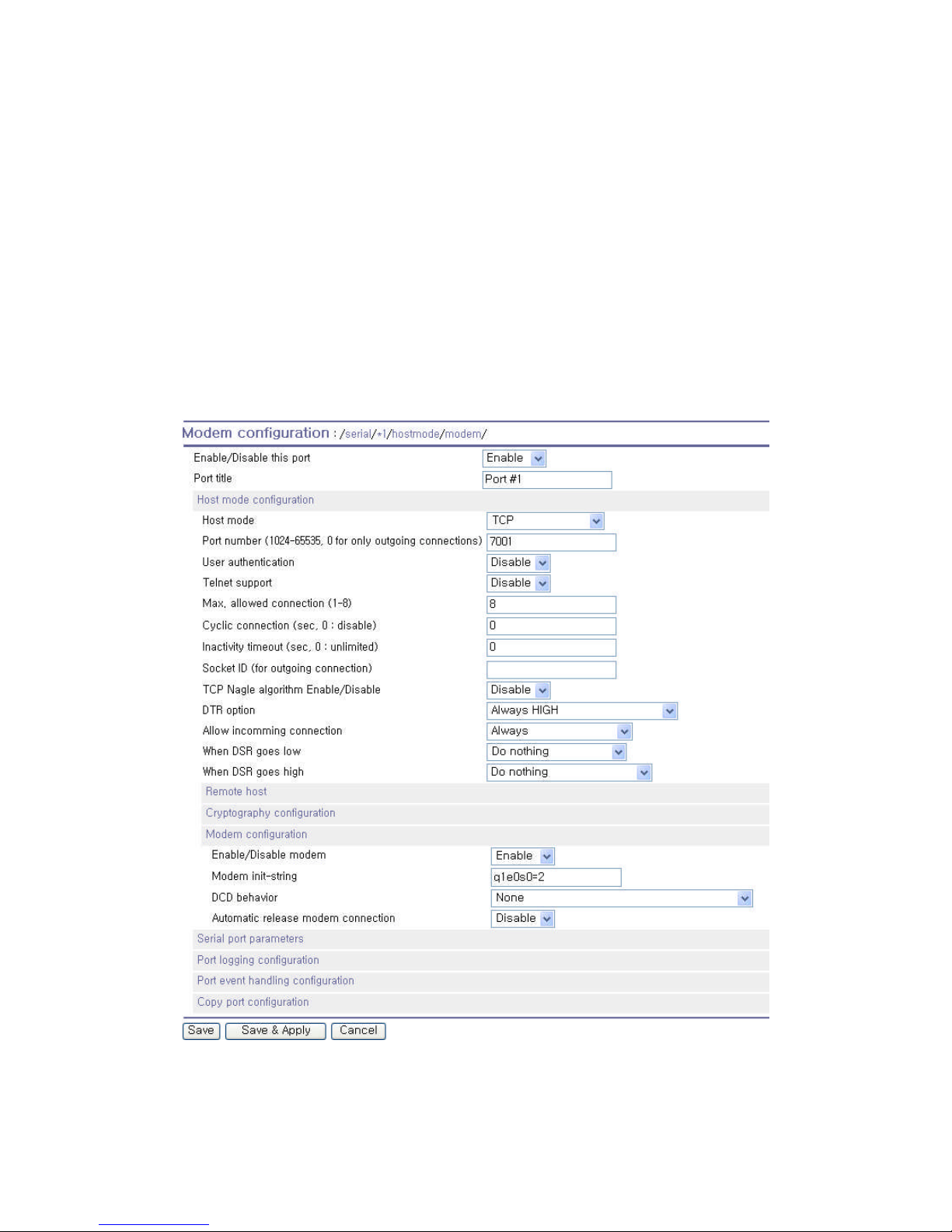
66
Automatic release modem connection
If Automatic release modem connection is set as Enable, modem connection will be closed by Pro
Series if all TCP connections are closed. If this option is set as Disable, modem connection will not be
closed by Pro Series even if all TCP connections are closed. Please note that actual phone line
connection will be closed if one of modems closes connection. That is, this option can be used for Pro
Series to allow disconnection of a modem connection by itself when all TCP connections are closed.
If user wants to use dial-out function, he should set DCD behavior as None because he must be able
to access modem connected to a serial port to send dial out command to the modem first.
Figure 4-18 Modem configuration
Page 67
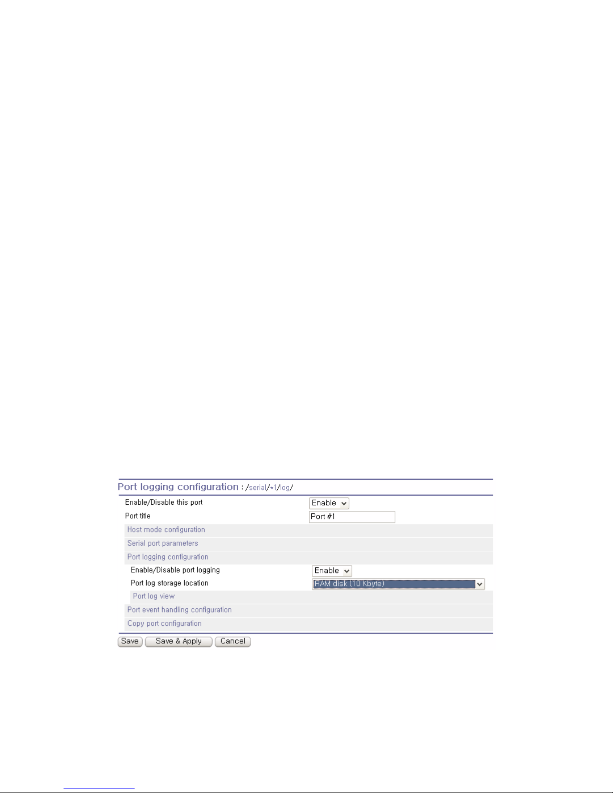
67
4.2.8. Port Logging
With the port logging feature, the data sent through the serial port is stored to MEMORY or a mounting
point on an NFS server.
Enable/disable port logging
This parameter defines whether to enable or disable the port-logging feature. The factory default
setting is [disabled].
Port log storage location
The port log data can be stored to the Pro Series’ internal memory or the mounting point on an NFS
server. If the internal memory is used to store port log data, the port log data will be cleared when the
Pro Series is turned off. To preserve the serial port log data, set the storage location to be the NFS
server. To do this, the user must configure the NFS server in advance. Please refer to the section 3.8.
NFS Server Configuration for details of NFS server configuration.
Port log buffer size
This parameter defines the maximum amount of port log data to be logged. When using internal
memory to store the log data, the total size of the port buffer cannot exceed 10 Kbytes.
When using an NFS server to store log data, the maximum port buffer size is unlimited. The user
should configure the NFS server to ensure that the port logging system works properly.
Figure 4-19 Port logging configuration
Page 68

68
4.2.9. Port Event Handling Configurations
The Pro Series provides a user for a means of monitoring or reacting to data from serial device
attached to a serial port of it through Port event handling configuration. Namely, user can define
keywords for each serial port that will trigger the email/SNMP notification or command sent to the
serial port directly on Port event handling configuration. This will enable the user to monitor the data
from the attached device or to manage/control a device attached serial port directly when pre-defined
keywords are detected. Also, the status of the connection between the Pro Series and the serial
device and the status of the TCP connection between the Pro Series and remote hosts could be
monitored and managed as well.
Each reaction can be configured individually upon each event. Reaction can be an email delivery,
SNMP trap sending, command sending or either combination of all reactions.
Port event handling
If the user wants to enable port event handling feature, set Port event handling as enable. This is a
global parameter so if this feature is disabled, the Pro Series does not take any actions on port events.
Notification interval
To prevent Pro Series from being trapped in handling port event, there is a Notification interval
parameter. Pro Series will send notification email or SNMP trap every Notification interval even it
detects predefined keyword within Notification interval. The smaller value of this parameter will result
in immediate response for predefined keyword and heavy usage of system resources. The largest
value accepted by user is recommended to prevent system resource usage minimization.
Note: The port command in keyword response is not affected by this parameter. Port command will be
sent immediately when the corresponding keyword is detected.
Email notification
This parameter enables or disables Email notification feature of the Pro Series. When Pro Series
sends Email notification, it uses the SMTP server configured in SMTP server configuration. If the
SMTP server is not configured correctly or disabled, Email feature will be disabled. For details of
SMTP server configurations and descriptions, please refer to section 3.4. SMTP Configuration.
Subject of Email
This parameter set the subject of Email that will be sent by Pro Series when pre-defined keyword is
detected.
Recipient’s Email address
This parameter set mail recipient who will receive notification mail when pre-defined keyword is
Page 69

69
detected.
SNMP trap notification
This parameter enables or disables SNMP trap notification feature of Pro Series.
Subject of SNMP trap
This parameter set the subject of SNMP trap that will be sent by Pro Series when pre-defined keyword
is detected.
SNMP trap receiver’s IP address
This parameter sets the IP address of SNMP trap receiver that will receive SNMP trap notification
when pre-defined keyword is detected.
SNMP trap community
This parameter sets a community that will be included in SNMP trap message when pre-defined
keyword is detected.
SNMP trap version
This parameter sets a version of SNMP trap, which will be sent when pre-defined keyword is detected.
Event keywords
The user can assign event keywords so that the Pro Series takes actions such as sending e-mail
notification, sending SNMP trap notification or sending pre-defined command to a serial port if the
keyword is detected at the serial port.
Event keyword
User can specify any words, which he/she wants to set as a keyword.
Email notification
User can select enable or disable for the Email notification action on keyword selected.
SNMP trap notification
User can select enable or disable for the SNMP trap notification action on keyword selected.
Port command
Pro Series supports direct reaction to a device attached to serial port when pre-defined keyword is
detected. User can specify command or string, which will be sent to a serial port on this menu.
Page 70
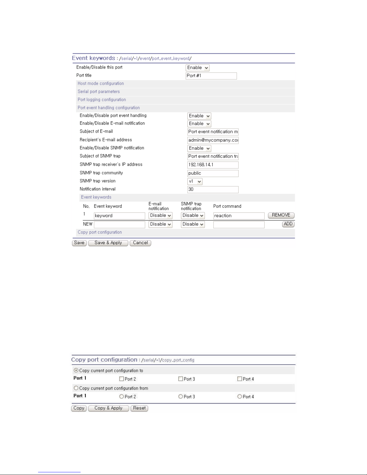
70
Figure 4-20
Port event-handling configurations
4.2.10. Copy Port Configuration
User can copy port configuration of one port to another. There are two methods in copying port
configuration. One is “Copy current port configuration to” specified ports and another is “Copy current
port configuration from” specified port.
Note: Port title, TCP port number and UDP port number are not copied by this function.
Figure 4-21 Copy port configuration
Page 71
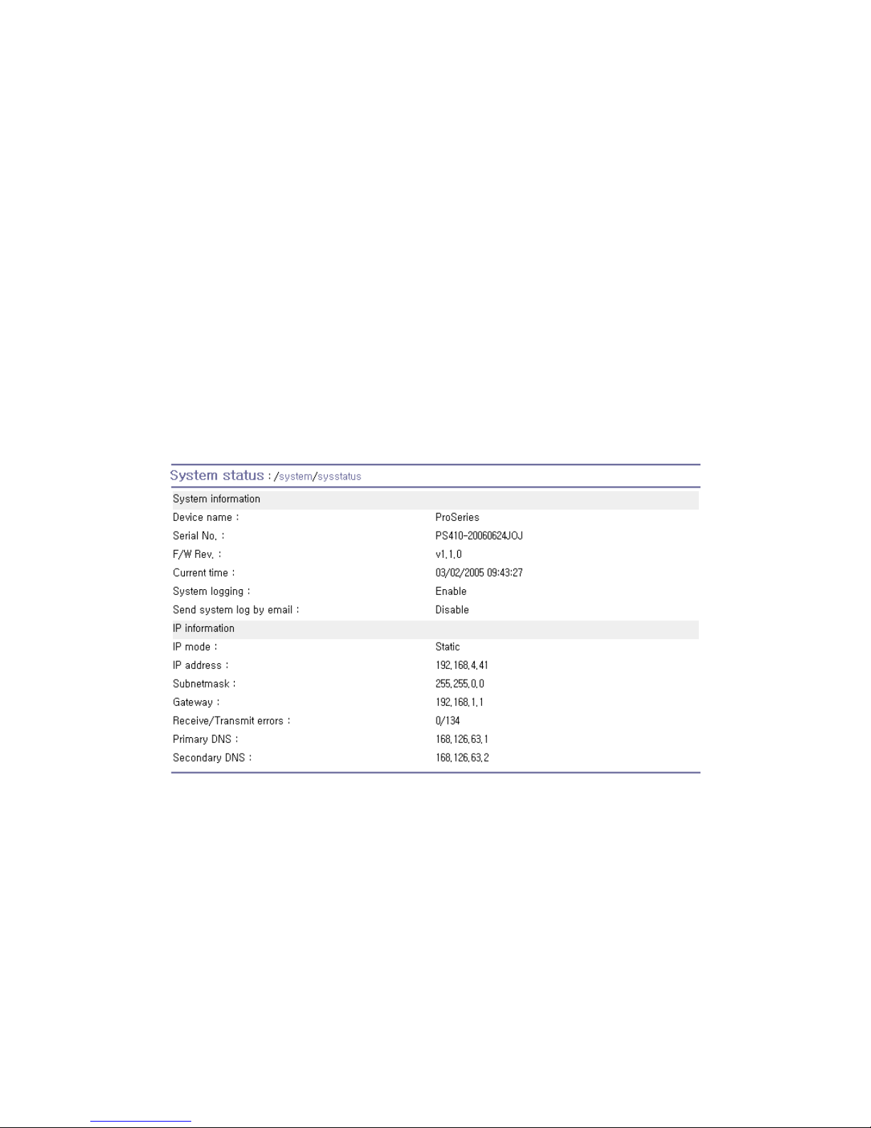
71
5. System Administration
The Pro Series displays the system status and the log data via a Status Display Screen. This screen is
used for management purposes. System status data includes the model name, serial number,
firmware version and the network configuration of the Pro Series. The Pro Series can also be
configured to deliver log data automatically via email to a specified recipient with the system-logging
feature.
The users can configure the Pro Series’ device name, date and time settings, and reload factory
default settings in this menu group. The users can also upgrade the firmware of the Pro Series using
the web interface, remote consoles or serial console.
5.1. System Status
Figure 5-1 System status display
5.2. System Logging
The Pro Series provides both the system logging feature and the system log status display. The user
may configure the Pro Series to enable or disable the system logging process, the system log buffer
size, as well as select the log storage location.
System log storage location
The system log can be stored in the Pro Series internal memory, the mounting point on an NFS
Page 72
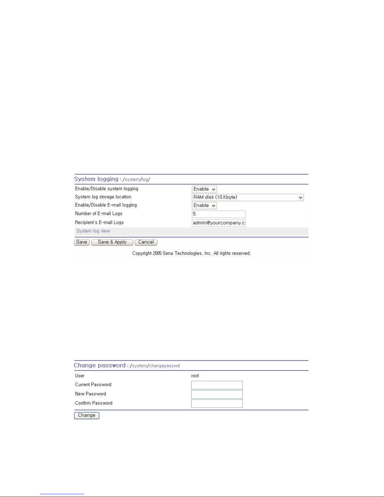
72
server or the SYSLOG server. If the internal memory is used to store system log data, the log data
will be cleared when the Pro Series is turned off. To preserve the system log data, set the storage
location to be SYSLOG server or NFS server. To do this, the user must configure the corresponding
media in advance. Unless the media is properly set up, the log will not be written to a specified storage
location properly.
The Pro Series can also be configured to send log data automatically if the number of logs unsent
reaches a pre-defined number. If enabled, the user must set parameters to initiate the creation of a
email. These parameters would include the number of logs required to trigger an email, the recipient’s
email address, etc. Figure 5-2 shows the configuration and system log view screen.
Figure 5-2 System log configuration and view
5.3. Change Password
The password for the administrative system user (root) of Pro Series can be changed using this menu.
This password is required when user wants to access serial console, telnet/ssh console or Web UI of
Pro Series. (Please refer to the section 5.9. User Administration for details about port user
management)
Figure 5-3 Changing the password
Page 73
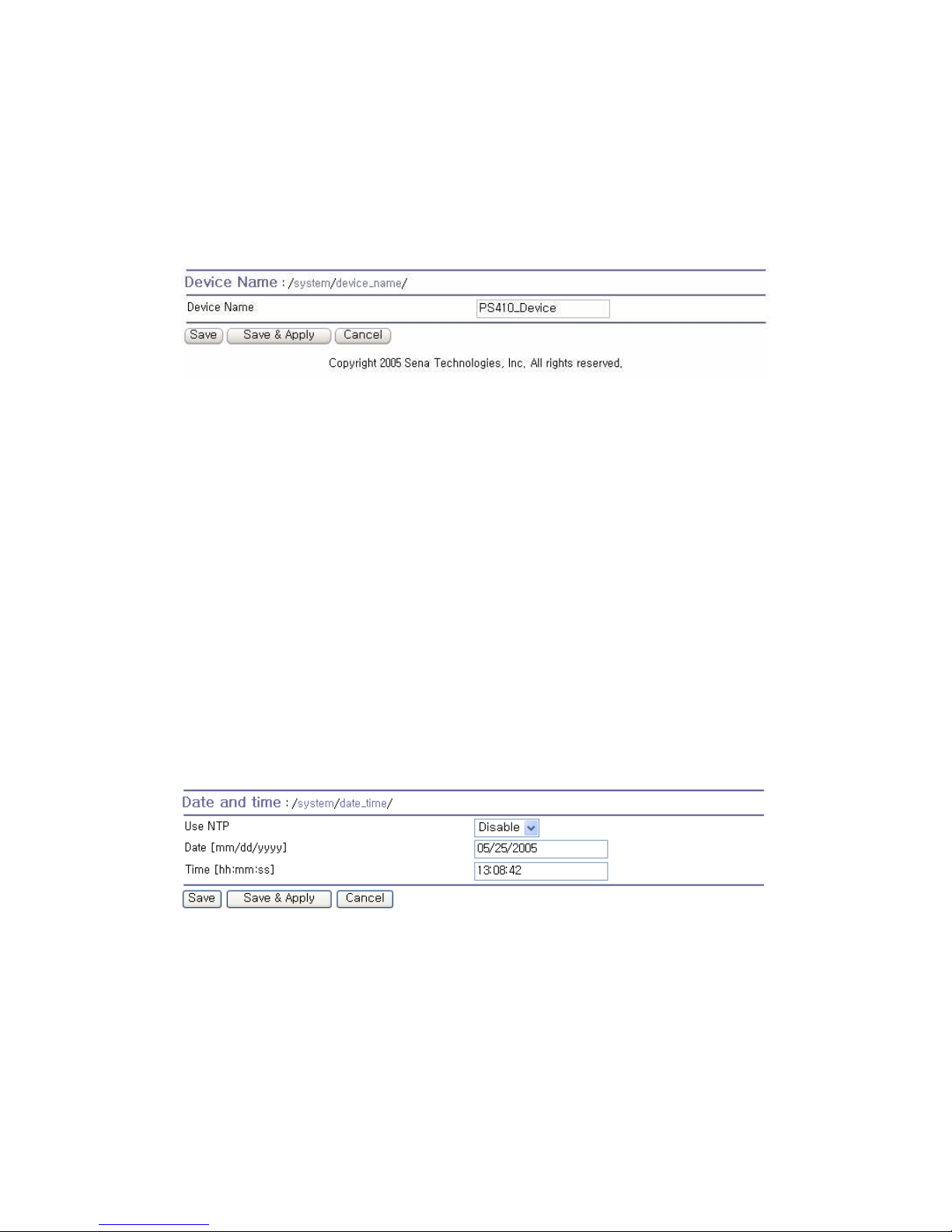
73
5.4. Device Name Configuration
The Pro Series has its own name for administrative purposes. Figure 5-4 shows the device name
configuration screen. When user changes Device name, hostname of Pro Series will be also changed.
Figure 5-4 Device name configuration
Please note that user cannot set space character as a device name. If user sets blank as Device
name then hostname is set as IP address of Pro Series automatically.
The device name is utilized for device identification at the management program, HelloDevice
Manager.
5.5. Date And Time Settings
The Pro Series maintains current date and time information. The PS410/810’s clock and calendar
settings are backed up by internal battery power. (Please note that PS110 does not have a battery for
internal clock. Current date and time setting will not be retained after system rebooting. So it is
recommended to use NTP server to maintain correct date and time in PS110 model)
The user can change the current date and time, as shown in Figure 5-5.
Figure 5-5 Date and time configuration
User also uses the NTP (Network Time Protocol) sever for setting the time of the Pro Series as shown
in Figure 5-6. If the NTP feature is enabled, the Pro Series will obtain the date and time information
from the NTP server at each reboot. If the NTP server is set to 0.0.0.0, the Pro Series will use the
default NTP servers. In this case, the Pro Series should be connected from the network to the Internet.
The user may also need to set the time offset from UTC depending on the users’ location.
Page 74
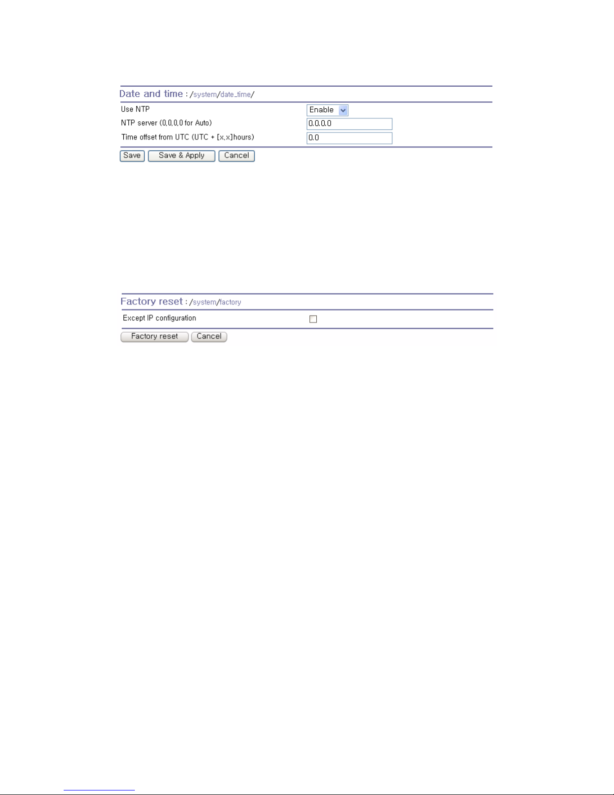
74
Figure 5-6 NTP configuration
5.6. Factory Reset
The user may restore the factory default settings at any time using this menu. (User can also restore
the factory default settings using the reset switch near by serial console port.)
Figure 5-7 Factory Reset
5.7. Configuration Management
The user may export the current configurations to a file at local machine and import the exported
configurations to current configurations.
The users can may restore the factory default settings at any time by selecting “Factory default” at
location property at the import part. Figure 5-8 shows the configuration management screen. The
following parameters should be properly set up in order to export / import configurations as follows:
Configuration export
Encrypt : Yes or No.
File name
Configuration import
Location : Location to import from. By selecting Factory default, the user may restore the factory
settings.
Configuration selection : Determines what kinds of configurations are imported.
Encrypt : If the location is Factory default, it has no effects.
URL : if the location is FTP or HTTP, write down address of configuration file.
Local path : Helps to browse the exported file at local machine if the location is local machine.
Page 75
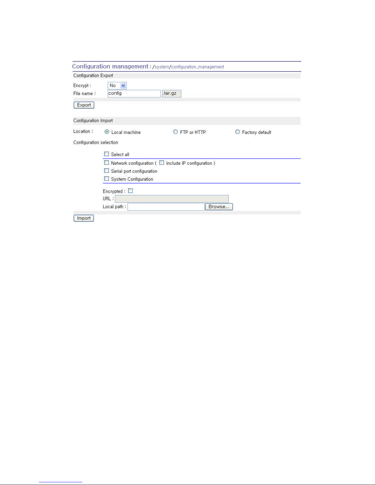
75
Figure 5-8 Configuration Management
To export the current configurations, follow this:
1. Select the encrypting option
2. Type the file name.
3. Click the [Export] button.
To import the exported configurations, follow this:
1. Select the location to import from.
2. Select the configurations to import.
3. Select the encrypting option.
4. Select the file to import from the file selection list box if location is neither local machine nor
factory default.
5. Select the file to import by clicking browse button if location is local machine.
6. Click the [Import] button.
Page 76
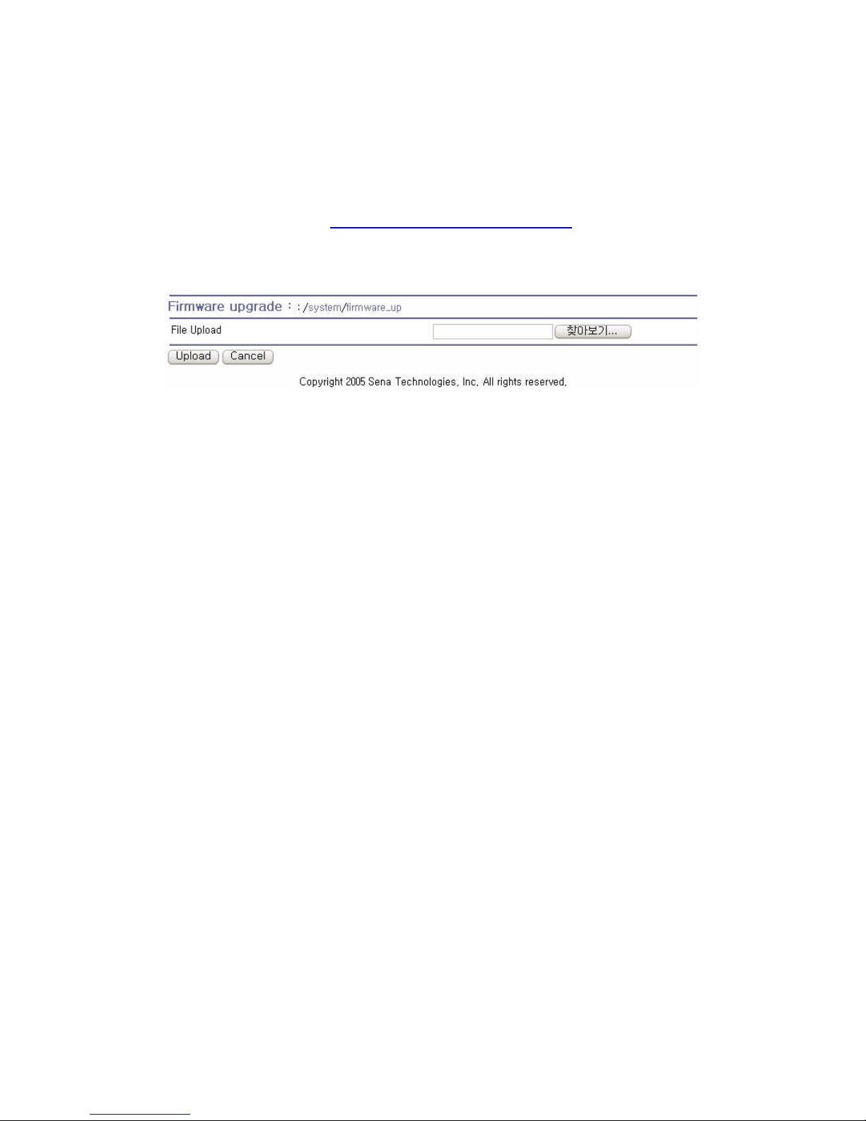
76
5.8. Firmware Upgrade
Firmware upgrades are available via serial, remote console or web interface. The latest upgrades are
available on the Sena web site at http://www.sena.com/support/downloads/.
Figure 5-9 shows the firmware upgrade web interface.
Figure 5-9 Firmware upgrade
To upgrade firmware via the web:
1. Select the latest firmware binary by clicking browse button.
2. Select and upload the selected version.
3. Once the upgrade has been completed, the system will reboot to apply the changes.
To use either a remote or serial console to upgrade your firmware, the TELENT/SSH or terminal
emulation program must support Zmodem transfer protocol. The previous settings will be retained
after the firmware upgrade.
To upgrade firmware via a remote console:
1. Obtain the latest firmware.
2. Connect the terminal emulation program using either TELENT/SSH or a serial console port.
(TELNET or SSH is recommended since the process of firmware upgrade by serial console
requires extremely long time.)
3. Select from the firmware upgrade menu as shown in Figure 5-10.
4. Follow the online directions and transfer the firmware binary file using the Zmodem protocol as
shown in Figure 5-11.
5. Once the upgrade has been completed, the system will reboot to apply the changes.
6. If the firmware upgrade fails, the Pro Series will display error messages as shown in Figure
5-12. It will also maintain the current firmware version.
Page 77
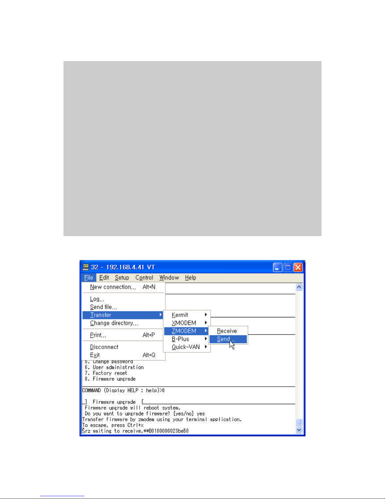
77
login: root
Password:
# editconf
_] / [________________________________________________________________________
1. Network configuration
2. Serial port configuration
3. System administration
________________________________________________________________________________
COMMAND (Display HELP : help)>3
_] System administration [____________________________________________________
1. System status
2. System logging
3. Device Name : PS110
4. Date and time
5. Change password
6. User Administration
7. Factory reset
8. Firmware upgrade
________________________________________________________________________________
COMMAND (Display HELP : help)>8
_] Firmware upgrade [_________________________________________________________
Do you want to upgrade firmware? [yes/no] yes
Transfer firmware by zmodem using your terminal application.
To escape, press Ctrl+X
**B0ff000005b157
Figure 5-10 Firmware upgrade using remote/serial console
Figure 5-11 Transfer binary file by Zmodem (TeraTerm Pro)
Page 78
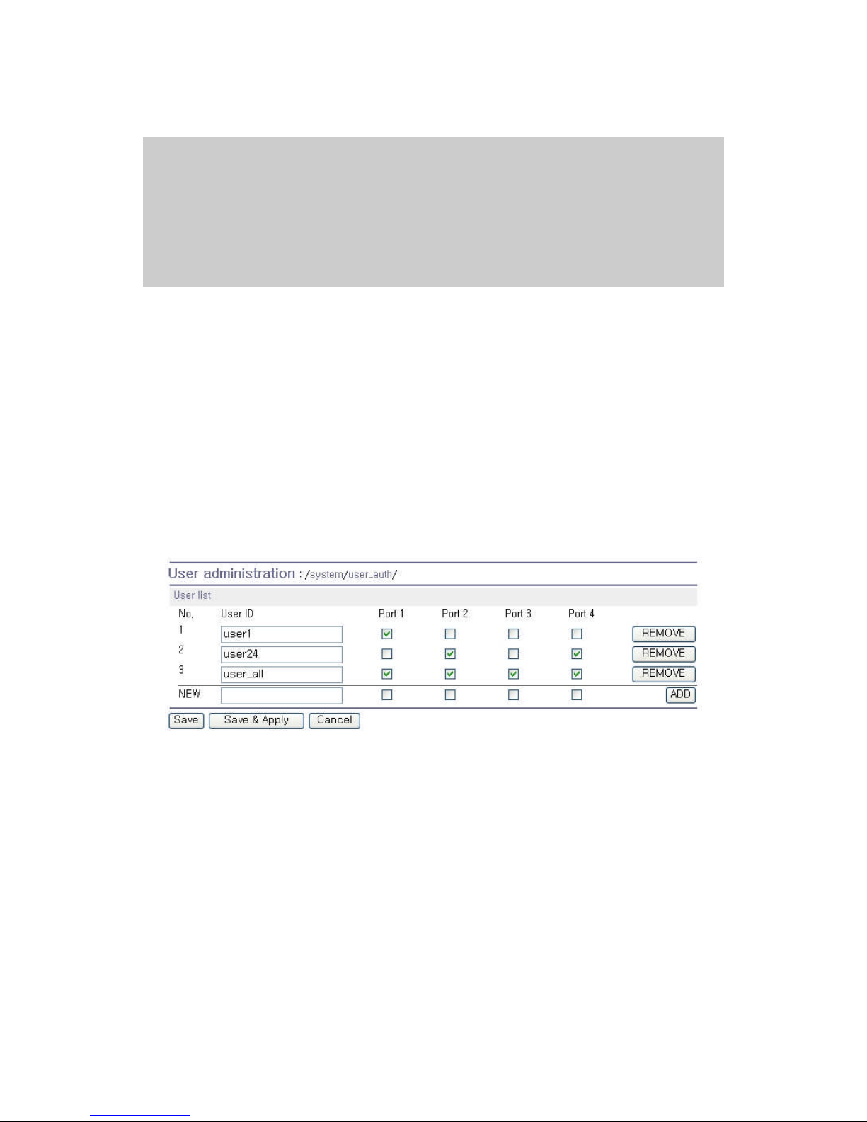
78
_] Firmware upgrade [_________________________________________________________
Do you want to upgrade firmware? [yes/no] yes
Transfer firmware by zmodem using your terminal application.
To escape, press Ctrl+X
**B0ff000005b157
**B0ff000005b157
**B0ff000005b157
**B0ff000005b157
Firmware upgrade failed !
Now reboot ...
Figure 5-12 Firmware upgrade failure message
5.9. User Administration
User can enable port authentication (see section 4.2.3.1. TCP Mode), then user should enter correct
user ID and password of each port when he tries to access the serial port.
The user ID and password for each serial port can be set using this menu. When user adds a new
user for serial port, he can also assign permissible serial ports to the user selectively, as shown on
Figure 5-13 Port user administration.
Figure 5-13 Port user administration
Note: System user (root) cannot access serial ports unless he is also added as a port user in this
menu.
To set the password for the port user or to change the configuration of each port user, click the
corresponding number associated with the port user on port user administration page, then port user
configuration page will be displayed as shown on Figure 5-14 Port user configuration.
Page 79
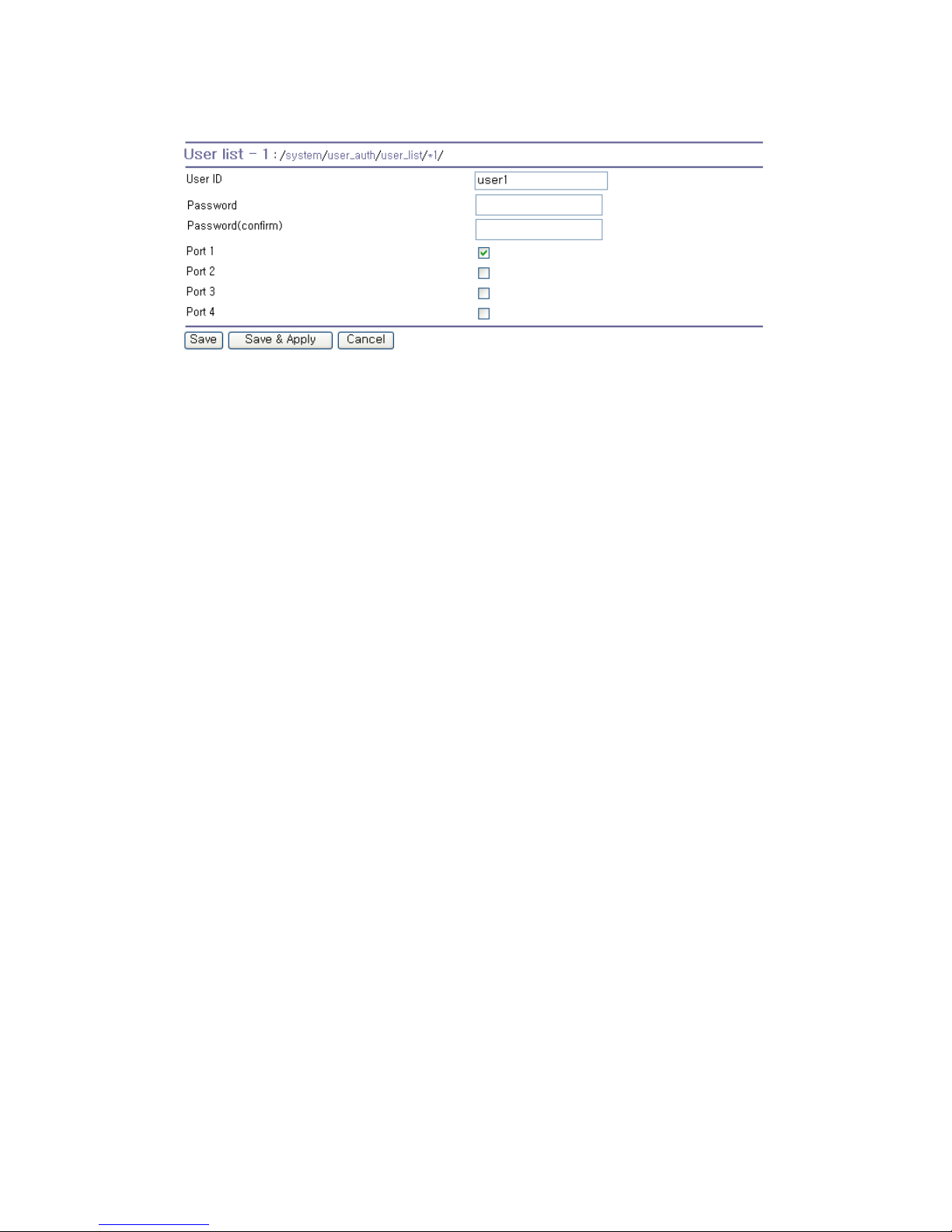
79
Figure 5-14 Port user configuration
Page 80
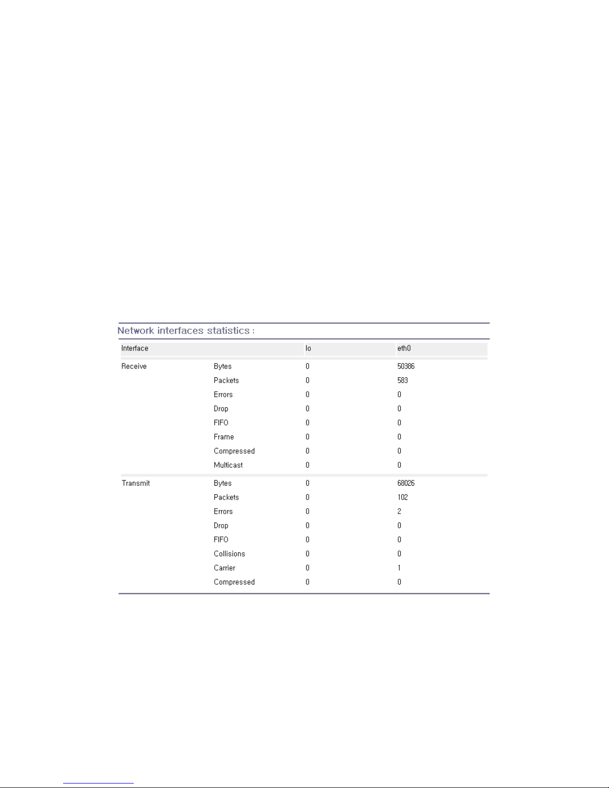
80
6. System Statistics
The Pro Series Web interface provides system statistics menus. The user can use these menus to
access statistical data and tables stored in the Pro Series memory. Network interfaces statistics and
serial ports statistics display statistical usage of the link layer, lo, eth and serial ports. IP, ICMP, TCP
and UDP statistics display usages of four primary components in the TCP/IP protocol suite.
6.1. Network Interfaces Statistics
Network interfaces statistics displays basic network interfaces usage of the Pro Series, lo and eth0. lo
is a local loop back interface and eth0 is a default network interface of Pro Series.
Figure 6-1 Network interfaces statistics
Page 81
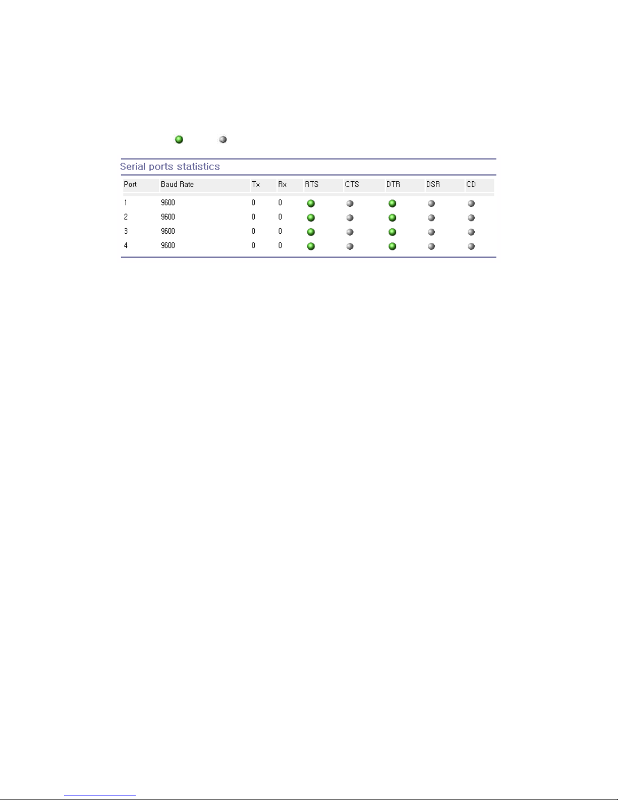
81
6.2. Serial Ports Statistics
Serial ports statistics displays the usage history of 32 serial ports, baud rate configurations and each
port’s pin status. ( : On : Off )
Figure 6-2 Serial ports status
6.3. IP Statistics
The IP Statistics screen provides statistical information about packets/connections using an IP
protocol. Definitions and descriptions of each parameter are described below:
Forwarding :
Specifies whether IP forwarding is enabled or disabled.
DefaultTTL :
Specifies the default initial time to live (TTL) for datagrams originating on a particular computer.
InReceives :
Shows the number of datagrams received.
InHdrErrors :
Shows the number of datagrams received that have header errors. Datagrams Received Header
Errors is the number of input datagrams discarded due to errors in their IP headers, including bad
checksums, version number mismatch, other format errors, time-to-live exceeded, errors discovered in
processing their IP options, etc.
InAddrErrors :
Specifies the number of datagrams received that have address errors. These datagrams are discarded
because the IP address in their IP header’s destination field was not a valid address to be received at
this entity. This count includes invalid addresses (for example, 0.0.0.0) and addresses of unsupported
Classes (for example, Class E).
Page 82

82
ForwDatagrams :
Specifies the number of datagrams forwarded.
InUnknownProtos :
Specifies the number of locally addressed datagrams received successfully but discarded because of
an unknown or unsupported protocol.
InDiscard :
Specifies the number of input IP datagrams for which no problems were encountered to prevent their
continued processing, but which were discarded (for example, for lack of buffer space). This counter
does not include any datagrams discarded while awaiting reassembly.
InDelivers :
Specifies the number of received datagrams delivered.
OutRequests :
Specifies the number of outgoing datagrams that an IP is requested to transmit. This number does not
include forwarded datagrams.
OutDiscards :
Specifies the number of transmitted datagrams discarded. These are datagrams for which no
problems were encountered to prevent their transmission to their destination, but which were
discarded (for example, for lack of buffer space.) This counter would include datagrams counted in
Datagrams Forwarded if any such packets met this (discretionary) discard criterion.
OutNoRoutes :
Specifies the number of datagrams for which no route could be found to transmit them to the
destination IP address. These datagrams were discarded. This counter includes any packets counted
in Datagrams Forwarded that meet this “no route” criterion.
ReasmTimeout :
Specifies the amount of time allowed for all pieces of a fragmented datagram to arrive. If all pieces do
not arrive within this time, the datagram is discarded.
ReasmReqds :
Specifies the number of datagrams that require reassembly.
Page 83
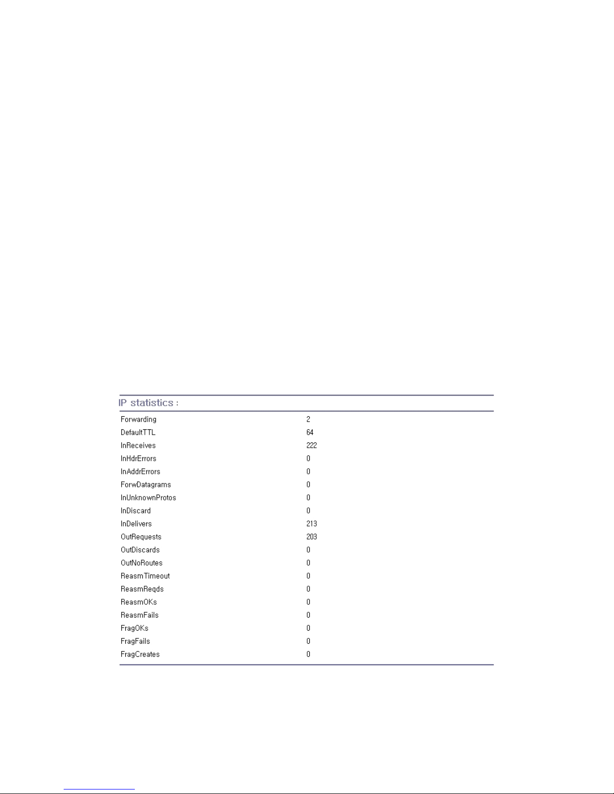
83
ReasmOKs :
Specifies the number of datagrams that were successfully reassembled.
ReasmFails :
Specifies the number of datagrams that cannot be reassembled.
FragOKs :
Specifies the number of datagrams that were fragmented successfully.
FragFails :
Specifies the number of datagrams that needs to be fragmented but couldn’t be because the IP header
specifies no fragmentation. For example, if the datagrams “Don’t Fragment” flag was set, the datagram
would not be fragmented. These datagrams are discarded.
FragCreates :
Specifies the number of fragments created.
Figure 6-3 IP statistics
Page 84

84
6.4. ICMP Statistics
The ICMP Statistics screen provides statistical information about packets/connections using an ICMP
protocol. Definitions and descriptions of each parameter are described below:
Figure 6-4 ICMP statistics
InMsgs, OutMsgs :
Specifies the number of messages received or sent.
InErrors, OutErrors :
Specifies the number of errors received or sent.
InDestUnreachs, OutDestUnreachs :
Specifies the number of destination-unreachable messages received or sent. A destinationunreachable message is sent to the originating computer when a datagram fails to reach its intended
destination.
Page 85

85
InTimeExcds, OutTimeExcds :
Specifies the number of time-to-live (TTL) exceeded messages received or sent. A time-to-live
exceeded message is sent to the originating computer when a datagram is discarded because the
number of routers it has passed through exceeds its time-to-live value.
InParmProbs, OutParmProbs :
Specifies the number of parameter-problem messages received or sent. A parameter-problem
message is sent to the originating computer when a router or host detects an error in a datagram’s IP
header.
InSrcQuenchs, OutSrcQuenchs :
Specifies the number of source quench messages received or sent. A source quench request is sent
to a computer to request that it reduces its rate of packet transmission.
InRedirects, OutRedirects :
Specifies the number of redirect messages received or sent. A redirect message is sent to the
originating computer when a better route is discovered for a datagram sent by that computer.
InEchos, OutEchos :
Specifies the number of echo requests received or sent. An echo request causes the receiving
computer to send an echo reply message back to the originating computer.
NEchoReps, OutEchoReps :
Specifies the number of echo replies received or sent. A computer sends an echo reply in response to
receiving an echo request message.
InTimestamps, OutTimestamps :
Specifies the number of time-stamp requests received or sent. A time-stamp request causes the
receiving computer to send a time-stamp reply back to the originating computer.
InTimestampReps, OutTimestampReps :
Specifies the number of time-stamp replies received or sent. A computer sends a time-stamp reply in
response to receiving a time-stamp request. Routers can use time-stamp requests and replies to
measure the transmission speed of datagrams on a network.
InAddrMasks, OutAddrMasks :
Specifies the number of address mask requests received or sent. A computer sends an address mask
request to determine the number of bits in the subnet mask for its local subnet.
Page 86

86
InAddrMaskReps, OutAddrMaskReps :
Specifies the number of address mask responses received or sent. A computer sends an address
mask response in response to an address mask request.
6.5. TCP Statistics
The TCP Statistics screen provides statistical information about packets/connections using a TCP
protocol. Definitions and descriptions of each parameter are described below:
RtoAlgorithm :
Specifies the retransmission time-out (RTO) algorithm in use. The Retransmission Algorithm can have
one of the following values.
0 : CONSTANT - Constant Time-out
1: RSRE - MIL-STD-1778 Appendix B
2: VANJ - Van Jacobson’s Algorithm
3: OTHER – Other
RtoMin :
Specifies the minimum retransmission time-out value in milliseconds.
RtoMax :
Specifies the maximum retransmission time-out value in milliseconds.
MaxConn :
Specifies the maximum number of connections. If is the maximum number is set to -1, the maximum
number of connections are dynamic.
ActiveOpens :
Specifies the number of active opens. In an active open, the client is initiating a connection with the
server.
PassiveOpens :
Specifies the number of passive opens. In a passive open, the server is listening for a connection
request from a client.
AttemptFails :
Specifies the number of failed connection attempts.
Page 87
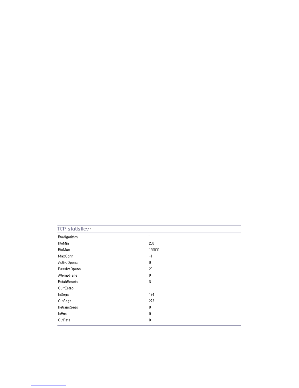
87
EstabResets :
Specifies the number of established connections that have been reset.
CurrEstab :
Specifies the number of currently established connections.
InSegs :
Specifies the number of segments received.
OutSegs :
Specifies the number of segments transmitted. This number does not include retransmitted segments.
RetransSegs :
Specifies the number of segments retransmitted.
RetransSegs :
Specifies the number of errors received.
OutRsts :
Specifies the number of segments transmitted with the reset flag set.
Figure 6-5 TCP statistics
Page 88

88
6.6. UDP Statistics
The UDP Statistics screen provides statistical information about packets/connections using a UDP
protocol. Definitions and descriptions of each parameter are described below:
InDatagrams :
Specifies the number of datagrams received.
NoPorts :
Specifies the number of received datagrams that were discarded because the specified port was
invalid.
InErrors :
Specifies the number of erroneous datagrams that were received. Datagrams Received Errors is the
number of received UDP datagrams that could not be delivered for reasons other than the lack of an
application at the destination port.
OutDatagrams :
Specifies the number of datagrams transmitted.
Figure 6-6 UDP statistics
Page 89

89
7. CLI Guide
7.1. Introduction
The root user can access the Linux console command line interface (CLI) of the Pro Series via the
serial console or TELENT/SSH. In the CLI, the user can perform standard Linux commands to view
the status of the Pro Series, edit the configuration, apply configuration changes.
7.2. Flash Partition
The Pro Series internal flash is partitioned as shown in the table below. The user can access files at
/var directory at his own risk. Simply accessing these files will not affect the Pro Series after
rebooting. However, if the user invokes the command saveconf, the changes in the configuration file
will be committed to the internal flash memory area of the Pro Series. This will result in the changes
being kept after the reboot sequence. Invalid configuration changes can affect the Pro Series behavior.
At worst, it may cause the Pro Series to become inoperable.
Block Type Mount point Size (KB)
Mtdblock0 Bios None 128
Mtdblock1 Kernel & ROM file system / 1024
Mtdblock2 CRAMFS (Read only) /mtd 2880
Mtdblock3 EXT2 (R/W) /cnf (normally
unmounted)
64
Total 4096
7.3. Supported Linux Utilities
7.3.1. Shell & Shell Utilities:
cat, echo, more, pwd
7.3.2. File And Disk Utils:
ls, cp, mv, rm, mkdir, rmdir, touch, gunzip, gzip, tar, df, du, vi, e2fsck,
mount, umount
7.3.3. System Utilities:
date, free, hostname, kill, killall, ps, reboot
7.3.4. Network Utilities:
ifconfig, iptables, route, ping
Page 90

90
7.4. Accessing CLI
Serial console:
1) Connect the console port of the Pro Series with the PC serial port
2) Run a PC terminal emulation program
3) Configure the PC serial port to: 9600-8-N-1 No flow control
4) Press <enter>
5) Login with the Pro Series root account
Telnet console:
1) telnet Pro_Series_ip_address
SSH console:
1) ssh -2 Pro_Series_ip_address
Note: The Pro Series support only SSH v2 protocol.
Page 91
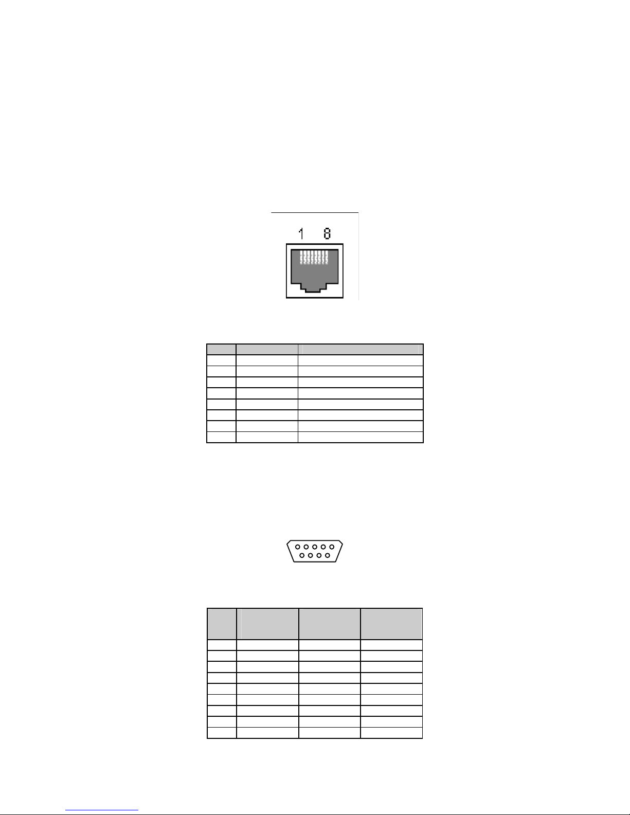
91
Appendix 1. Connections
A 1.1. Ethernet Pinouts
The Pro Series uses a standard Ethernet connector, which is a shielded connector that is compliant
with the AT&T258 specifications. TableA-1 shows the pin assignment and wire color.
Figure A-1 Pin layout of the RJ45 connector
Table A-1 Pin assignment of the RJ45 connector for Ethernet
Pin Description Color
1 Tx+ White with orange
2 Tx- Orange
3 Rx+ White with green
4 NC Blue
5 NC White with blue
6 Rx- Green
7 NC White with brown
8 NC Brown
A 1.2. Console And Serial Port Pinouts
The pin assignment of the PS110/PS410/PS810 DB9 connector is summarized in Table A-2. Each pin
has a function according to the serial communication type configuration.
6 7 8 9
1 2 3 4 5
Figure A-2 Pin layout of the DB-9 connector
Table A-2 Pin assignment of DB-9 connector for console and serial port
Pin RS232
(console and
serial ports)
RS422
(serial ports
only)
RS485
(serial ports
only)
1 DCD Tx+ Tx+
2 Rx RX+ RX+
3 Tx RTS+ 4 DTR CTS+ 5 GND GND GND
6 DSR TX- TX7 RTS RTS- 8 CTS RX- RX9 - CTS- -
Page 92
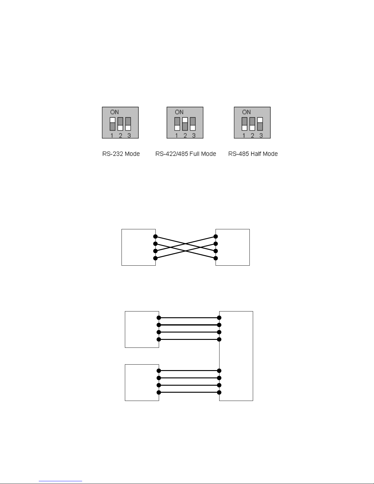
92
The serial communication type can be set by DIP switch near by serial port. (Only for PS110 and
PS410) To change the serial communication type, change the position of each DIP switch as shown
below. But please note that the power of the Pro Series should be turned off before changing the serial
communication type.
Figure A-3 Serial communication type and DIP switch configuration
A 1.3. Ethernet Wiring Diagram
Figure A-4 Ethernet direct connection using crossover Ethernet cable
Figure A-5 Ethernet connection using straight through Ethernet cable
Tx+(1)
Tx-(2)
Rx+(3)
Rx-(6)
HelloDevice
Hub
Tx+(1)
Tx-(2)
Rx+(3)
Rx-(6)
Remote Host
Tx+(1)
Tx-(2)
Rx+(3)
Rx-(6)
Tx+(1)
Tx-(2)
Rx+(3)
Rx-(6)
Tx+(1)
Tx-(2)
Rx+(3)
Rx-(6)
HelloDevice
Remote Host
Tx+(1)
Tx-(2)
Rx+(3)
Rx-(6)
Page 93
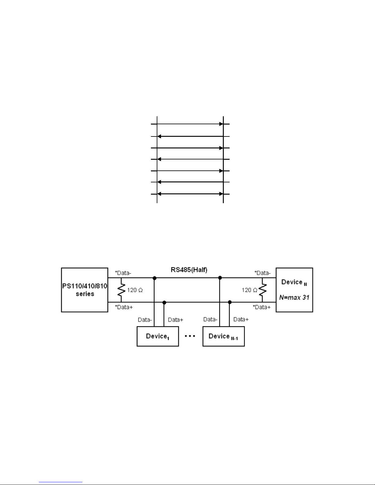
93
A 1.4. Serial Wiring Diagram
A 1.4.1. RS232 Serial Wiring Diagram
Tx(3)
Rx(2)
RTS(7)
CTS(8)
DTR(4)
DSR(6)
GND(5)
Rx
Tx
CTS
RTS
DSR
DTR
GND
HelloDevice
Serial Device
RS232
Figure A-6 RS232 wiring diagram
A 1.4.2. RS422/485 Serial Wiring Diagram
*Data+ means that coupling of Tx+(1) pin and Rx+(2) pin
*Data- means that coupling of Tx-(6) pin and Rx-(8) pin
Figure A-7 RS485 wiring diagram
Page 94
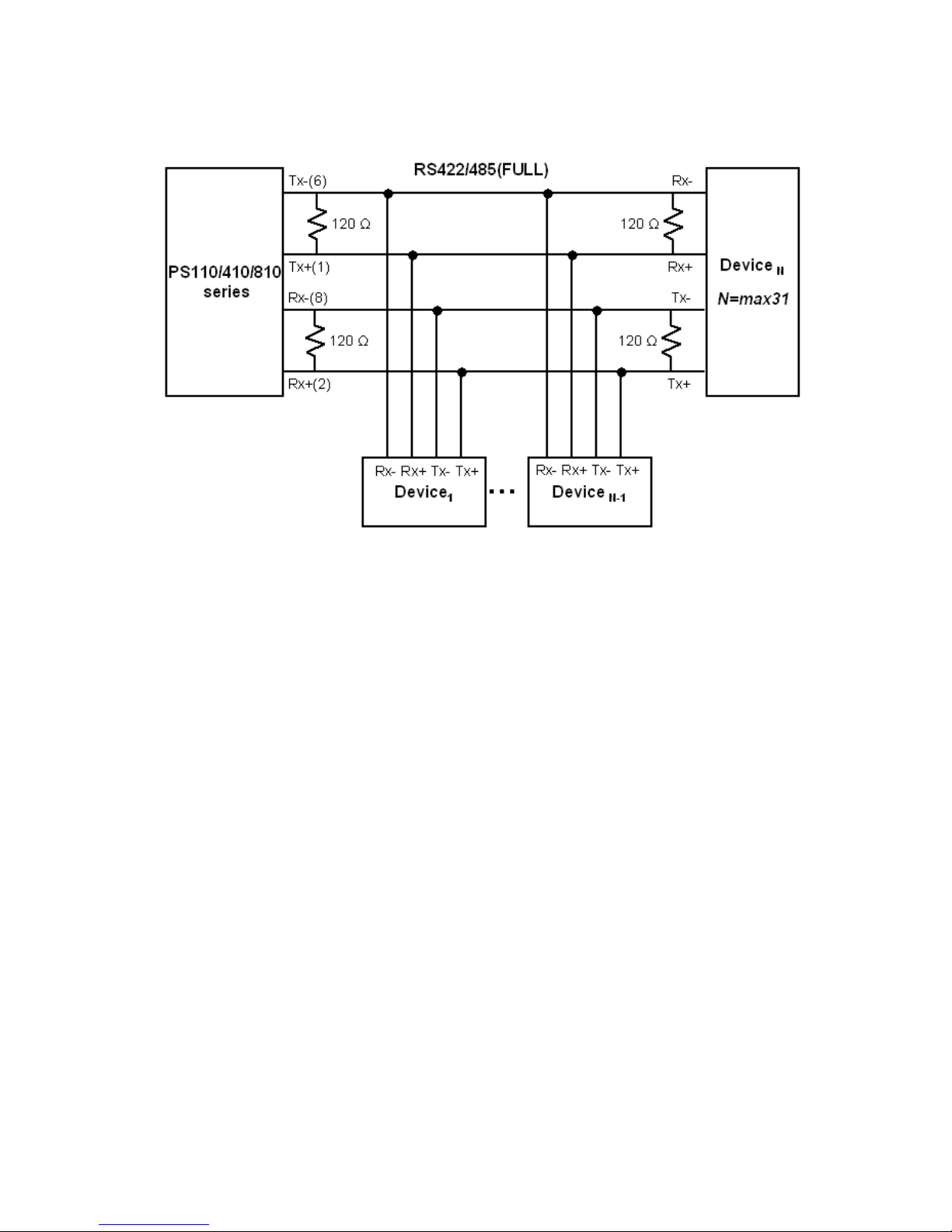
94
* Termination Resistor at Tx side can be omitted if the signal status is good.
Figure A-8 RS422 wiring diagram
Page 95

95
Appendix 2. Pro Series Configuration files
A 2.1. port1.conf
/serial/*1/parameter/baudrate=9600
/serial/*1/parameter/databit=0
/serial/*1/parameter/stopbit=0
/serial/*1/parameter/parity=0
/serial/*1/parameter/flowcontrol=0
/serial/*1/parameter/interchar_to=0
/serial/*1/parameter/dtr_option=0
/serial/*1/parameter/dsr_option=0
/serial/*1/modem/modem_init_string=q1e0s0=2
/serial/*1/modem/modem_dcd_option=0
/serial/*1/modem/modem_auto_disconnection_enable=0
/serial/*1/modem/modem_enable=0
/serial/*1/event/event_email_enable=0
/serial/*1/event/event_snmp_enable=0
/serial/*1/event/event_notification_interval=30
/serial/*1/event/event_enable=0
/serial/*1/hostmode/accept_unlisted=1
/serial/*1/hostmode/send_unlisted=1
/serial/*1/enable=1
/serial/*1/title=Port #1
/serial/*1/hostmode/mode=0
/serial/*1/hostmode/port=7001
/serial/*1/hostmode/userauth=0
/serial/*1/hostmode/telnet=0
/serial/*1/hostmode/max_connection=8
/serial/*1/hostmode/cyclic_time=0
/serial/*1/hostmode/inactive_time=0
A 2.2. filter.conf
/network/filter/specification/telnet=1
/network/filter/specification/ssh=1
/network/filter/specification/http=1
/network/filter/specification/https=1
/network/filter/specification/port1=1
/network/filter/specification/port2=1
/network/filter/specification/port3=1
/network/filter/specification/port4=1
A 2.3. snmp.conf
/network/snmp/syscontact=administrator
/network/snmp/sysname=ProSeries
/network/snmp/syslocation=my location
/network/snmp/sysservice=7
/network/snmp/powerontrapenable=0
/network/snmp/authtrapenable=1
/network/snmp/linkuptrapenable=0
/network/snmp/logintrapenable=0
/network/snmp/nms/*1=0.0.0.0 public 0
/network/snmp/nms/*2=0.0.0.0 public 0
/network/snmp/nms/*3=0.0.0.0 public 0
Page 96

96
/network/snmp/nms/*4=0.0.0.0 public 0
/network/snmp/trap/*1=0.0.0.0 public 0
/network/snmp/trap/*2=0.0.0.0 public 0
/network/snmp/trap/*3=0.0.0.0 public 0
/network/snmp/trap/*4=0.0.0.0 public 0
Page 97

97
Appendix 3. Well-known Port Numbers
Port numbers are divided into three ranges: Well Known Ports, Registered Ports, and Dynamic and/or
Private Ports. Well Known Ports are those from 0 through 1023. Registered Ports are those from 1024
through 49151. Dynamic and/or Private Ports are those from 49152 through 65535.
Well Known Ports are assigned by IANA, and on most systems, can only be used by system
processes or by programs executed by privileged users. Table A-3 shows some of the well-known port
numbers. For more details, please visit the IANA website: http://www.iana.org/assignments/port-
numbers
Table A-3 Well-known port numbers
Port number Protocol TCP/UDP
21 FTP(File Transfer Protocol) TCP
22 SSH (Secure Shell) TCP
23 Telnet TCP
25 SMTP(Simple Mail Transfer Protocol) TCP
37 Time TCP, UDP
39 RLP (Resource Location Protocol) UDP
49 TACACS, TACACS+ UDP
53 DNS UDP
67 BOOTP server UDP
68 BOOTP client UDP
69 TFTP UDP
70 Gopher TCP
79 Finger TCP
80 HTTP TCP
110 POP3 TCP
119 NNTP (Network News Transfer Protocol) TCP
161/162 SNMP UDP
443 HTTPS TCP
Page 98

98
Appendix 4. Guide To The Bios Menu Program
A 4.1. Overview
The bios menu provides a way to recover the Pro Series unit, by using TFTP, as a disaster recovery
option and to diagnose the system hardware. If the user presses the <ESC> key within 3 seconds
after the Pro Series unit is powered up, the user will enter the bios menu program. From this menu
program, the user can set various system parameters, test system hardware, and perform firmware
upgrades.
Note: For PS110, the bios menu will be displayed only when the Data/Console switch is located at the
Console side.
A 4.2. Main Menu
After entering the bios menu program, the user will see following main menu page:
----------------------------------------------------------------------------BIOS v1.0.0 (c) 1998-2005 Sena Technologies, Inc.
-----------------------------------------------------------------------------
----------------------------------------------------------------------------Welcome to Boot Loader Configuration page
----------------------------------------------------------------------------Select menu
1. RTC Configuration
2. Hardware test
3. Firmware upgrade [S/W Version : v1.0.0]
4. Exit and boot from flash
5. Exit and reboot
<ESC> Back, <ENTER> Refresh
----->
Figure A-9 Main Menu Page of Bios Menu
A 4.3. RTC Configuration Menu
Using the RTC configuration menu, the user can set the system time of the Pro Series. (There is no
RTC configuration menu in case of PS110)
-----------------------------------------------------------------------------
RTC Configuration
----------------------------------------------------------------------------Select Menu
1. Data(mm/dd/yy) : 05/19/05
2. Time(hh:mm:ss) : 15:02:28
Page 99

99
<ESC> Back, <ENTER> Refresh
----->1
Enter Current Data(mm/dd/yy) : 05/20/05
Press the ENTER key to continue!!
-----------------------------------------------------------------------------
RTC Configuration
----------------------------------------------------------------------------Select Menu
1. Data(mm/dd/yy) : 05/20/05
2. Time(hh:mm:ss) : 15:02:41
<ESC> Back, <ENTER> Refresh
----->2
Enter Current Data(hh:mm:ss) : 15:03:40
Press the ENTER key to continue!!
-----------------------------------------------------------------------------
RTC Configuration
----------------------------------------------------------------------------Select Menu
1. Data(mm/dd/yy) : 05/20/05
2. Time(hh:mm:ss) : 15:03:41
<ESC> Back, <ENTER> Refresh
----->
Figure A-10 RTC configuration within Bios Menu Program
A 4.4. Hardware Test Menu
Using the Hardware test menu, the user can test hardware components. There are three hardware
test modes:
- One time
- Looping (without External test in Auto test)
- Looping (with External test in Auto test)
If the user selects One time, an auto test or each component test is performed just once. In this mode,
the ping test to the remote host (server IP address) and UART test are also performed once.
If the user selects Looping (without External test in Auto test), the auto test is performed repeatedly
until the user presses the <ctrl-c> keys. In this mode, the ping test to the remote host (server IP
address) and UART test are not performed.
Note: To perform the test on the Ethernet and UART properly, the user must connect an Ethernet
cable to the Ethernet port of the Pro Series and must plug the loopback connector to all the serial ports
of the Pro Series. There must exist a remote host with a valid IP address. The default server IP
address is 192.168.0.128 and it can be changed using the [Firmware Upgrade] menu. Otherwise, the
test may not be performed properly.
----------------------------------------------------------------------------Hardware Test
----------------------------------------------------------------------------Select menu
0. Test Mode - One Time
Page 100

100
1. Auto test
2. DRAM test
3. FLASH test
4. EEPROM test
5. Ethernet test
6. UART Mode test
<ESC> Back, <ENTER> Refresh
-----> 0
----------------------------------------------------------------------------Hardware Test
----------------------------------------------------------------------------Select menu
0. Test Mode - Looping(Without External test in Auto Test)
1. Auto test
2. DRAM test
3. FLASH test
4. EEPROM test
5. Ethernet test
6. UART Mode test
<ESC> Back, <ENTER> Refresh
-----> 0
----------------------------------------------------------------------------Hardware Test
----------------------------------------------------------------------------Select menu
0. Test Mode - Looping(With External test in Auto Test)
1. Auto test
2. DRAM test
3. FLASH test
4. EEPROM test
5. Ethernet test
6. UART Mode test
<ESC> Back, <ENTER> Refresh
-----> 0
----------------------------------------------------------------------------Hardware Test
----------------------------------------------------------------------------Select menu
0. Test Mode - One Time
1. Auto test
2. DRAM test
3. FLASH test
4. EEPROM test
5. Ethernet test
6. UART Mode test
<ESC> Back, <ENTER> Refresh
----->
Figure A-11 Hardware test menu within Bios Menu Program
When the user selects [Auto test], a test of all the hardware components is performed automatically.
******* Hardware auto-detect and auto-test *******
[DRAM]
DRAM Test ---------------------------------------------[ PASSED]
[FLASH]
FLASH Test ---------------------------------------------[ PASSED]
[EEPROM]
EEPROM Test ---------------------------------------------[ PASSED]
[ETHERNET]
ETHERNET Test ---------------------------------------------[ PASSED]
[UART]
<--Internal Loop Test-->
Port # 1 test in progressing(MODE)------------------------[ RS232]
 Loading...