

Page 1

- 1 -
1
Parani100
For Wireless Multi-Serial Communications,
based on Bluetooth Technology
Enabling Wireless Serial
Communications
Users Guide
Version 1.0.0
2005-03-07
Page 2

- 2 -
2
Copyright Information
Copyright 1998-2004, Sena Technologies, Inc. All rights reserved.
Sena Technologies reserves the right to make any changes and improvements to its product
without providing prior notice.
Trademark Information
Parani™. is a trademark of Sena Technologies, Inc.
Windows® is a registered trademark of Microsoft Corporation.
Ethernet® is a registered trademark of XEROX Corporation.
Notice to Users
Proper back-up systems and necessary safety devices should be utilized to protect against
injury, death or property damage due to system failure. Such protection is the responsibility of
the user.
This device is not approved for use as a life-support or medical system.
Any changes or modifications made to this device without the explicit approval or consent of
Sena Technologies will void Sena Technologies of any liability or responsibility of injury or loss
caused by any malfunction.
Technical Support
Sena Technologies, Inc.
210 Yangjae-dong, Seocho-gu
Seoul 137-130, Korea
Tel: (+82-2) 573-5422
Fax: (+82-2) 573-7710
E-Mail: support@sena.com
Website: http://www.sena.com
Page 3

- 3 -
3
Revision History
Revision Date Name Description
V1.0.0 2005-03-04 D.H. Shin Initial Release
Page 4

- 4 -
4
Table of Contents
1.Introduction......................................................................................................................... 6
1.1 Overview.................................................................................................................... 6
1.2 Package Check List...................................................................................................7
1.3 Product Specification ................................................................................................ 7
2. Getting Started ................................................................................................................... 9
2.1 External View............................................................................................................. 9
2.2 LED indicators......................................................................................................... 10
2.3 Connecting Parani100 to host................................................................................. 11
3. Installation........................................................................................................................ 12
3.1 Network Settings..................................................................................................... 12
3.2 LAN Access Profile.................................................................................................. 16
3.3 Firmware Download................................................................................................. 16
3.3.1 Firmware Upgrade via Xmodem.................................................................... 17
3.3.2 Firmware Upgrade via TFTP.......................................................................... 17
3.4 Serial Port................................................................................................................ 20
3.5 Reset/Reboot/Quit................................................................................................... 21
4. Configuration.................................................................................................................... 22
4.1 Configuration via Parani100 software .................................................................... 22
4.1.1 When Parani100 is connected to PC directly............................................... 22
4.1.2 Log in Parani100 software............................................................................. 22
4.1.3 Operation Mode............................................................................................. 24
4.1.4 Bluetooth ....................................................................................................... 32
4.1.5 Connections................................................................................................... 33
4.1.6 Neighborhoods.............................................................................................. 35
4.1.7 Repeater ......................................................................................................... 36
4.1.8 Parani100 information................................................................................... 37
4.2 Configuration via WEB............................................................................................ 38
4.2.1 Parani100 Configuration................................................................................ 38
4.2.2 Operation Mode............................................................................................. 39
4.2.3 Network Setting ............................................................................................. 41
4.2.4 Restore Factory Setting................................................................................. 42
Appendix A. Control Commands......................................................................................... 43
A .1 Basic Commands ................................................................................................... 43
Page 5

- 5 -
5
A .2 Commands for Server Mode.................................................................................. 44
A .3 Commands for Client Mode................................................................................... 46
A .4 Commands for Vertex Mode .................................................................................. 47
A .5 Commands for Serial Hub Mode........................................................................... 47
A .6 Commands for Bluetooth Configuration............................................................... 48
A .7 Commands for Bluetooth Connection Management............................................ 50
A .8 Other Commands ................................................................................................... 52
Appendix B. Discovery Protocol ......................................................................................... 54
Page 6

- 6 -
6
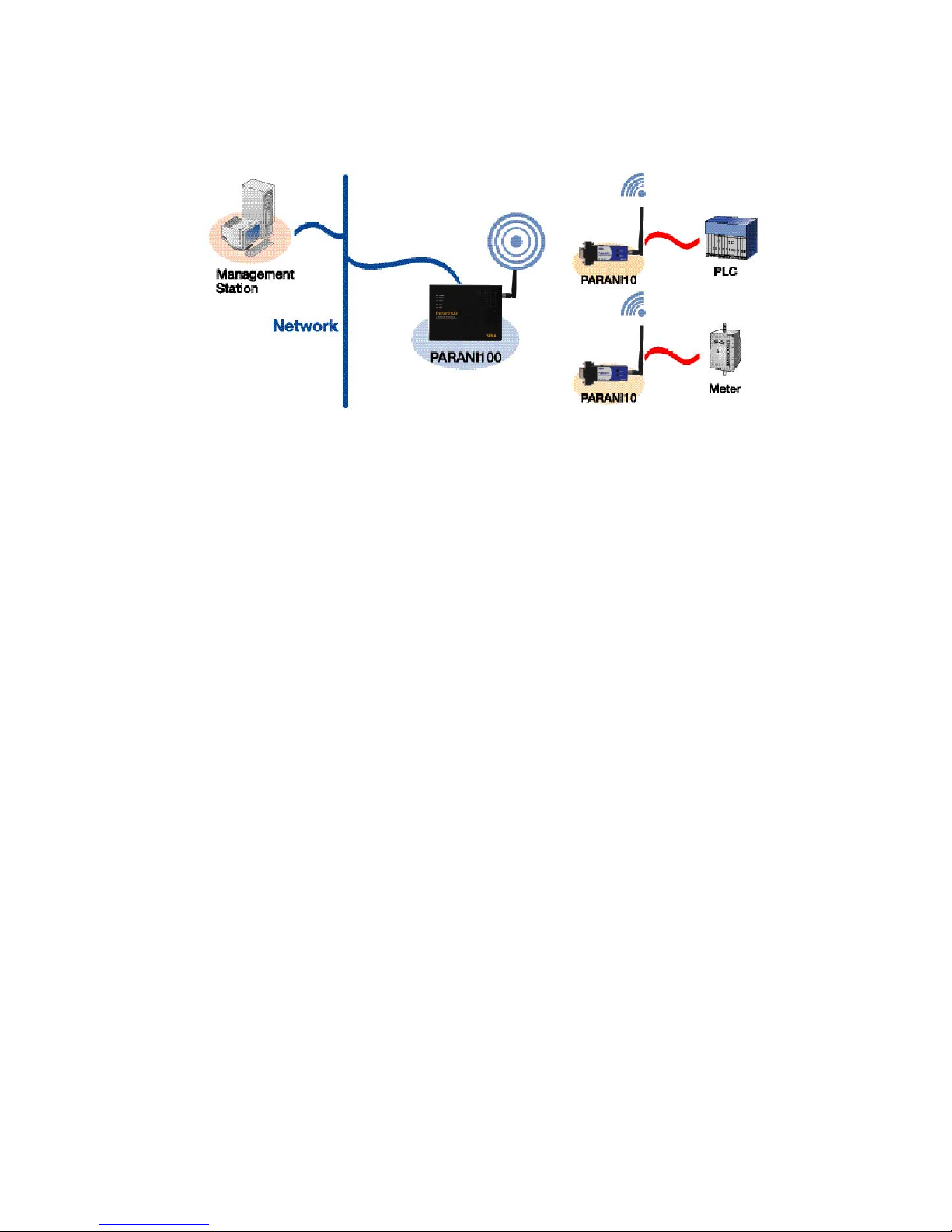
1.Introduction
1.1 Overview
The Parani100 enables multiple Bluetooth devices to connect to the Ethernet network
simultaneously and without delay when they are within range. The Parani100 provides Class 1
Bluetooth wireless connectivity to Ethernet/Fast Ethernet. It supports all Bluetooth devices
compatible with Bluetooth Profiles for the Serial Port, Dial-up Networking, LAN Access and PAN.
Along with the Serial Port Profile support, the Parani100 is the ideal solution for the replacement
of the wired serial port application.
The Parani100 supports versatile host modes for various user applications, i.e. TCP Server
and Client modes for TCP/IP-Bluetooth replay applications, Vertex mode for multicasting,
Repeater mode, Serial Hub mode and RS232 mode.
The Parani100 runs on embedded Linux operating system, with Flash memory for easy
software upgrades, and built-in Web server and Web interface for quick installation, and remote
configuration and management. The Parani100 uses the RADIUS protocol for user
authentication.
Typical application areas of the Parani100 include:
• Truck/Bus monitoring system
• Car Diagnostics
• Wireless POS system
• Wireless Factory monitoringPLC programming
• Wireless machine (healthcare/industrial) monitoring
• Wireless Printing
• Wireless logistics
Page 7
-7 -
1
Fig. 1.1.1 Application Diagram
1.2 Package Check List
- DC Power Adapter
- Serial Data Cable
- Ethernet Cross Cable
- Dipole antenna
- CD-ROM, including the Parani100 Manager Software, COM Port Redirector,
Tips_Serial/IP Com Port Redirector and manual
1.3 Product Specification
Ethernet Interface
. 10/100 Base Ethernet with RJ45 connector
. Supports Static IP and Dynamic IP address
Bluetooth Interface:
. Bluetooth v1.1, Class I
. Level - 18dBm
. Profiles
Serial Port, LAN Access, PAN, Dial up Networking
. Working distance: 10m ~ 400m
Page 8

- 8 -
8
Network Protocols
. HTTP, FTP, Telnet, DHCP client
. SNMP v1/v2/v3
. PPP server and PPP tunneling
. RADIUS
Management
. Windows Utility
. Web, Telnet, Serial Console
. Modem AT command set
Diagnostic LED
. Power, Status, Error, EXT and INT
Power
5VDC, .2A@ 5V
Environmental
. Operating temperature: 5? to 50? , Storage temperature: -40? to 66?
. Humidity: 90% Non-condensing
Physical properties
. Dimension (L x W x H)
147 x 112 x 32 (mm) , 5.8 x 4.4 x 1.3 (in.), 225g
Approvals
. FCC (A), CE
Warranty
1-year limited warranty
Page 9
- 9 -
9
2. Getting Started
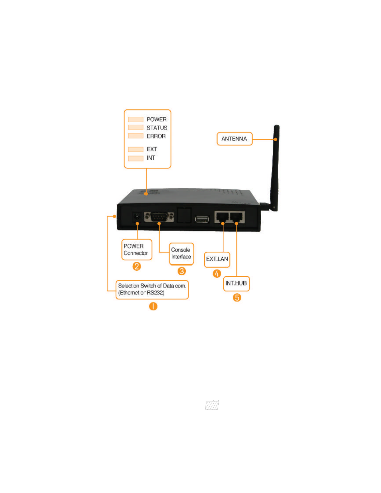
2.1 External View
<Fig. 1.3.1> Parani100 external view
(1) DIP Switch
Users may select several different methods of data communication with the Host.
Default setting is TCP/IP communication using no.4 RJ45 marked EXT , but if users
need, data communication by no.3 RS232 Interface marked “IOIOI” is also
possible.
• If DIP switch is on the side of drawing , Parani100 communicates with Host
via Ethernet line (TCP/IP).
• If users want to use RS232 com. please change the direction of switch in the
Page 10

- 10 -
10
opposite direction.
(2) Power Port: For Power Adapter connection
(3) RS232 Interface marked “IOIOI”:
For Parani100 network configuration via RS232 serial cable - One RS232 serial
cable, both ends female DB-9 interfaces, are provided with the Parani100.
This port can be used for both Configuration of Parani100 and Data communication
with Host.
(4) RJ45 marked EXT.: For connection to Host or HUB devices. For connection to PC,
use a Crossed cable; for connection to HUB, use Straight
Ethernet cable.
(5) RJ45 marked INT.: For HUB port connection to another Parani100. This is for
expansion of connections more than 14.
2.2 LED Indicators
- POWER: POWER ON/OFF Status
- STATUS: Parani100 Status
- ERROR: Error Event Status
- LINE/ACT1, LINE/ACT2: RJ45 connections Status
STATUS LED ERROR LED Description
ON OFF Normal
Blinking OFF Connecting to Station Parani100
(In Repeater Mode)
OFF ON Internal Bluetooth module operation malfunction
ON Blinking LAN connection Error
(Connecting to ADSL or waiting for DHCP
server response)
Flashing Flashing Upgrading Firmware
DO NOT turn off Parani100 during firmware
upgrade; turning off Parani100 during firmware
update may cause malfunction.
Page 11

- 11 -
11
2.3 Connecting Parani100 to host
Step 1: Connect the power jack to the power connector of the Parani100 using DC power
adapter included in the package. If power is properly supplied, the LEDs for ‘Power’ and ‘Status’
will maintain a solid green color.
Step 2: Connect the one end of the Ethernet cable to the ‘EXT’ port of the Parani100 and the
other to the Ethernet network. If the cable is properly hooked up, the Parani100 will have a valid
connection to the Ethernet network by indicating ‘EXT’ LED becomes green and is blinking if
there’s any corresponding packet traffic.
Step 3: Only for 1st time installation, attach the serial console cable to the Parani100. You are
ready to install the Parani100 using serial console.
Page 12
- 12 -
12
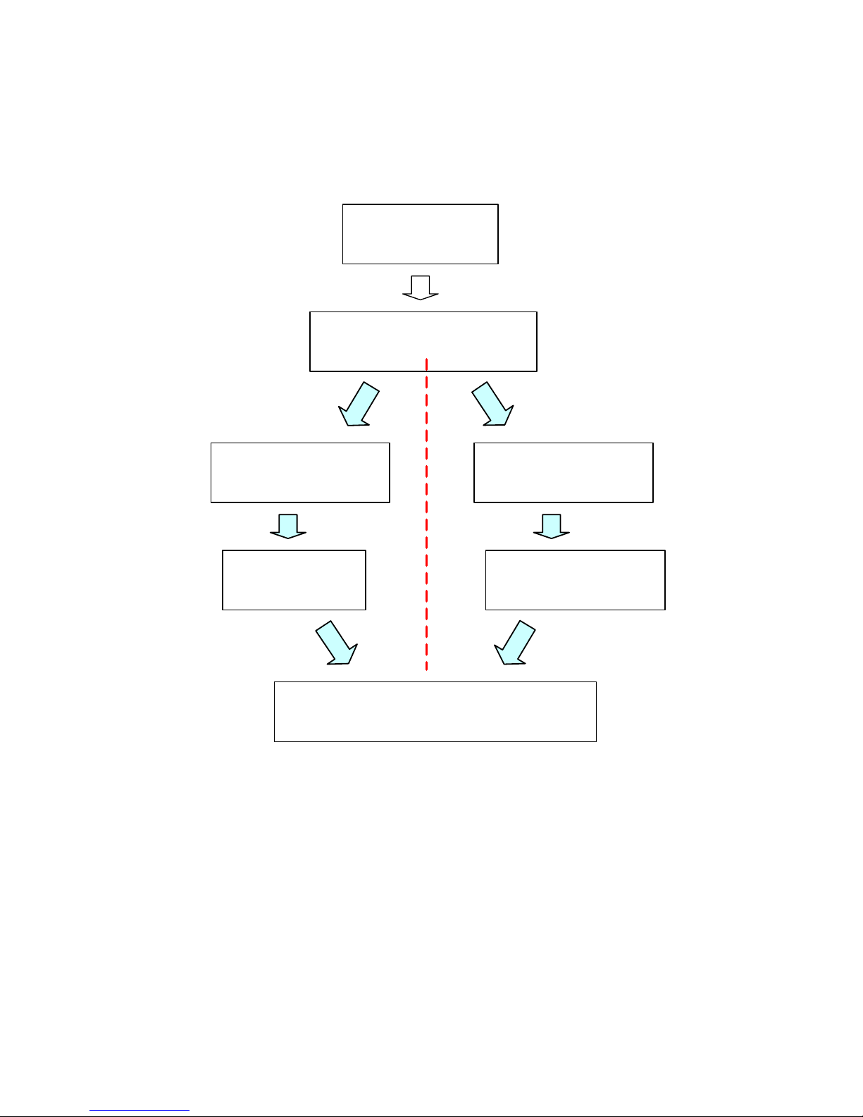
3. Installation
3.1 Network Settings
(1) Parani100 power-up; ‘POWER’ and ‘STATUS’ LEDs display green
(2) Parani100 network configuration: connect Parani100 to PC via RS232 cable
(3) Open HyperTerminal
(4) Set PC COM port;
Baud rate 115200 / 8 Data bit / non-parity / 1 stop bit / no hardware flow control
RS232 Mode
Parani100 Installation
Network Configuration
Serial Port Configuration
Change of DIPswitch
Configuration via serial cable
Mode configuration
Connection from Bluetooth Terminal device
(Parani10)
TCP/IP mode
Page 13
- 13 -
13
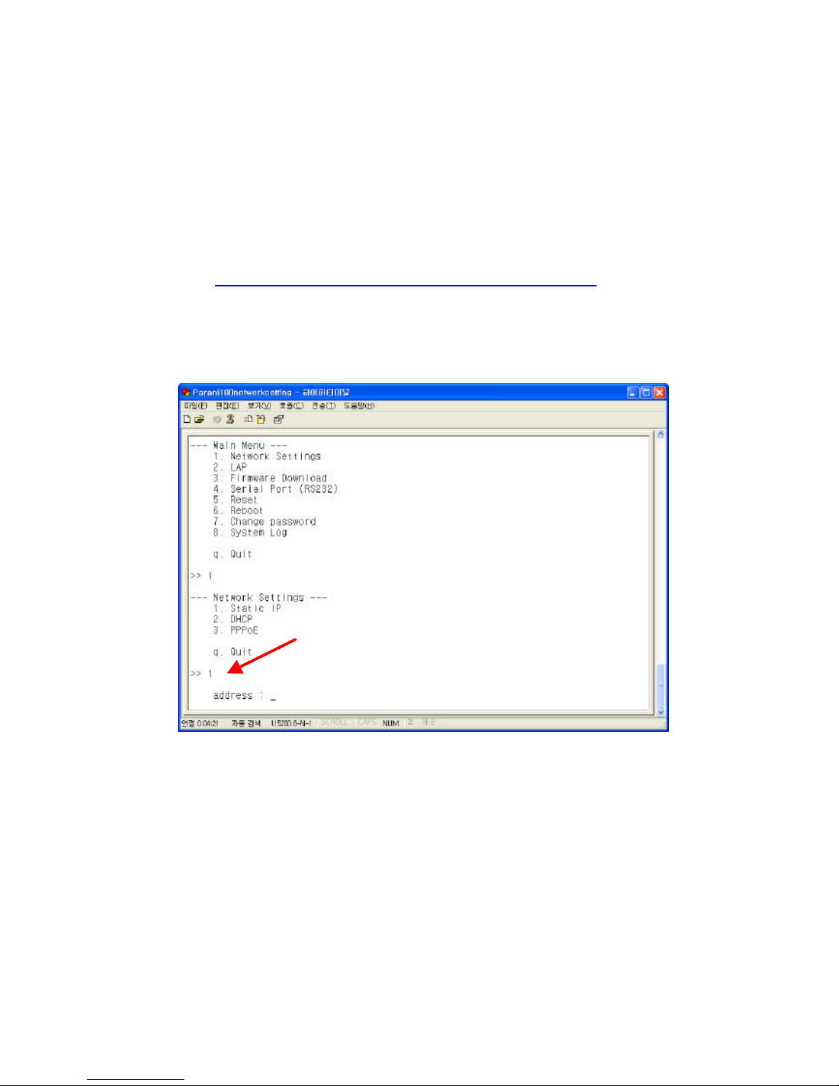
(5) Press Enter key; the following information as is displayed on a HyperTerminal
screen; If Parani100 prompts Login ID / password, default values are:
Login: admin
Password: 11111
(6) Default Parani100 IP address factory setting is 192.168.1.10. Please revise
settings to reflect the user’s appropriate networking environment IP address.
(7) To revise Network Settings, Enter “1” as displayed below.
(8) Network Settings sub menu will be displayed.
(9) If No.1, Static IP, is selected, the following is displayed on screen:
(10) Enter user Static IP address. In the example below, 192.168.0.3 is entered for
the Parani100 IP address. Enter the user appropriate network IP address.
Page 14

- 14 -
14
(11) Please enter your Netmask/Gateway/DNS information, as shown below:
(12) Press Enter: Parani100 will prompt reboot request. Enter ‘Y’ [Yes]; press Enter
to reboot Parani100 to apply the revised Network Settings.
(13) Enter Login ID and Password. Default ID: admin, Password: 11111
Page 15
- 15 -
15
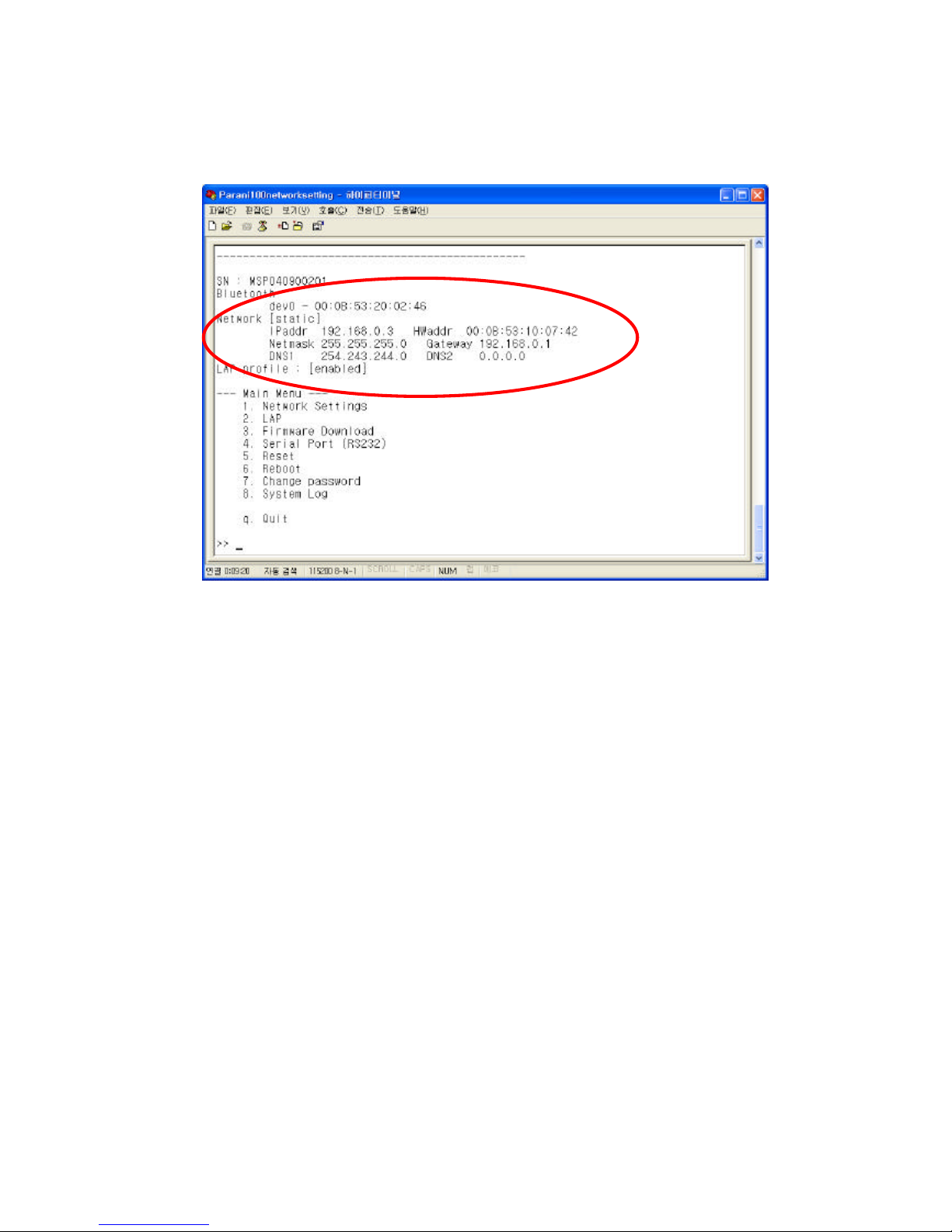
(14) Revised Network settings are displayed
<An example: Revised Network Settings>
(15) Networking configuration is complete. The preceding example shows static IP
assignment to Parani100. The user should select static, DHCP or PPPoE IP as
needed.
Page 16
- 16 -
16
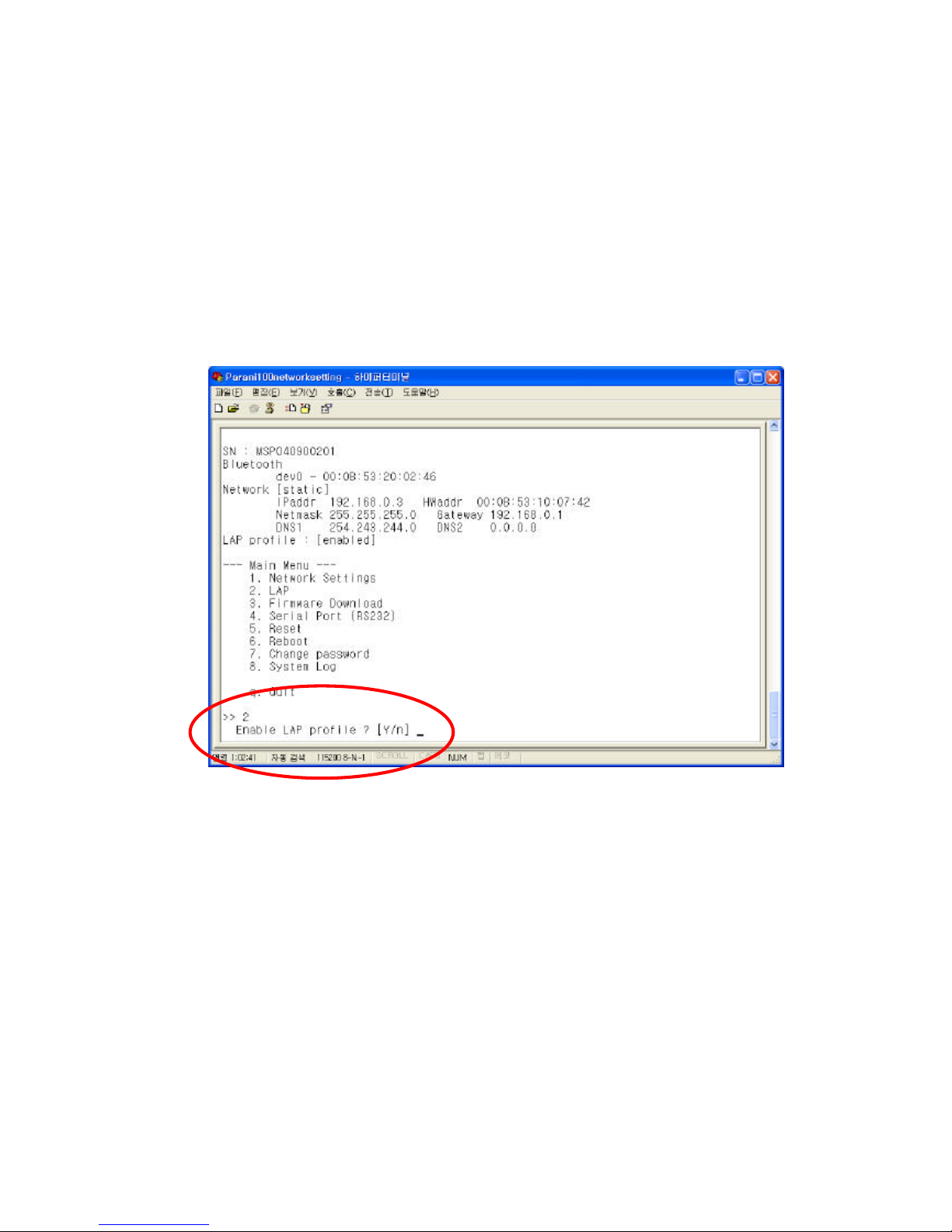
3.2 LAN Access Profile
Parani100 supports LAN Access Profile for Bluetooth networking Access Point. By direct
connection of Parani100 to ADSL, the internet is accessible via Bluetooth.
Select menu 2. LAP by entering ‘2’; Parani100 prompts for LAP profile enable/disable. Select
‘Y’ [Yes] to enable or ‘N’ [No] to disable LAP profile.
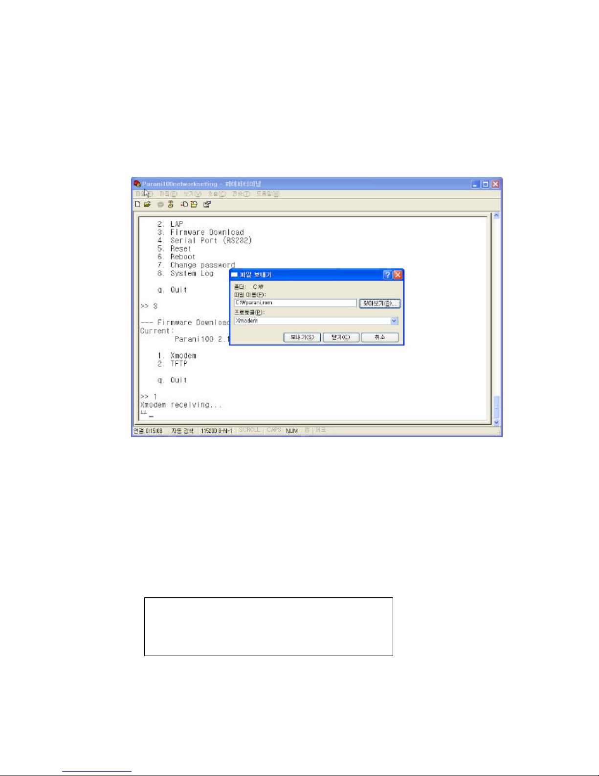
3.3 Firmware Download
Parani100 enables users to upgrade the firmware. The SENA customer support team offers
available firmware upgrades via Xmodem or TFTP user download; menu no. 3. Firmware
Download.
During Firmware download, STATUS and ERROR LEDs flash. DO NOT TURN OFF
Parani100 during firmware download. Turning off Parani100 during firmware download may
result in operation malfunction.
Page 17
- 17 -
17
There are two methods of firmware upgrade: 1. Xmodem 2. TFTP.
3.3.1 Firmware Upgrade via Xmodem
Users may upgrade the firmware using Xmodem protocol via RS232 serial cable.
<Upgrade firmware via Xmodem>
3.3.2 Firmware Upgrade via TFTP
• Users may upgrade the firmware using TFTP via Crossed cable.
3. Firmware Download ? 2.TFTP
• Then you will get following screen:
TFTPd ready. Send firmware using TFTP.
Windows 2000/XP:
tftp –i 192.168.222.7 put <filename>
* Here, a sample IP address, 192.168.222.7 has been assigned to Parani100. User
Page 18

- 18 -
18
must use your own IP address. User must put your own IP address.
• Please keep this serial console connected.
• After you save the Parani100 upgrade ROM file to your PC, please open COMMAND
window as in below.
• Users need to make sure that the upgrade ROM file is in the same location or users
need to specify the exact location to send the ROM file to the connected Parani100 via
Crossed Ethernet cable.
• Below window is showing the procedure of sending ROM file named “parani.rom” to
the connected Parani100 via TFTP.
• Users will be able to check the status of firmware upgrade in Serial console.
Page 19

- 19 -
19
• During upgrade, LEDs will flashing and users should NOT turn off Parani100 this time.
If user cannot send the ROM file, please check the network connection status.
• Once ROM file is delivered to the connected Parani100, the upgrade firmware will be
recorded to memory. During this time both STATUS LED and ERROR LED will flashing
speedily. NEVER turn off Parani100 during this firmware recording.
• Once finished, please resupply power to Parani100 for applying.
Page 20

- 20 -
20
3.4 Serial Port
Serial port of Parani100 can be used for both Configuration and Data communication. For
configuration, users need to change the DIPswitch of Parani100 to the right.
Users may set configuration of serial port communication in this menu.
Below figure is showing that ‘115200 bps 8-N-1 hardware’ which means ‘115200 bps, 8 data bit,
None parity, 1 stop bit, hardware flow control (RTS/CTS).
Configurable ranges:
Baud rate 1200 ~ 115200 bps
Character size 8, 7, 6, 5 bits
Parity Check None / Even / Odd
Stop Bit 1 bit or 2 bits
Flow Control
Hardware (RTS/CTS),
Software (XOn/Off),
None
Page 21

- 21 -
21
For applying changed configuration, please RESUPPLY the power, and then Parani100 will start
to operate as RS232 mode.
Advice: If you need to do data communication via RS232 port, you do not
need to configure Network settings.
3.5 Reset/Reboot/Quit
Entering no. 5, Parani100 RESET, in the main menu, restores all factory Default value settings.
REBOOT restarts Parani100 for new configuration application.
QUIT instantly aborts current processing.
Page 22

- 22 -
22
4. Configuration
Once users are finished configuring network settings using serial console. Users need to select
the operation mode of Parani100. Following three (3) ways can be used for selection of
operation mode:
1. Via Parani100 configuration software
2. Via Telnet (Control port)
3. Via Web browser (Internet Explorer, etc.)
In this chapter, a guide on usage of the Parani100 configuration software will be introduced.
How to configure via Telnet or Web browser will be introduced in the Appendix.
4.1 Configuration via Parani100 software
4.1.1 When Parani100 is connected to PC directly
If users are going to connect Host PC and Parani100 directly using a crossed cable, network
settings as in the chapter 3.1 will not be required.
Parani100 has factory settings: Static IP 192.168.1.10
For communication with Parani100, set the IP of Host PC to have proper address.
If you connected Parani100 to the Network, not to the Host PC, skip this chapter and go to
next chapter 4.1.2.
Open your Network Connections and see Property information of Local Network.
Change your IP address to Static:
IP: 192.168.1.11
Subnet: 255.255.255.0
Gateway: 192.168.1.1
These settings for direct communication only with Parani100 connected.
4.1.2 Log in Parani100 software
For easier configuration and monitoring on a specific Parani100, which has been installed
locally or remotely, users may use Parani100 software.
Page 23

- 23 -
23
Start Parani100 software, and press “Search” button on the left side.
Please select one Parani100 you would like to access and press “Connect” button.”
Page 24

- 24 -
24
You will need to enter UserID/Password: admin/11111
4.1.3 Operation Mode
Parani100 may be set to different type of modes, so users may have to select one for its own
application. There are 6 types of modes: Server, Client, Vertex, Repeater, Serial Hub, and
RS232.
Page 25

- 25 -
25
• Operation Mode
This shows current type of Mode.
• Mode Change
Users may change and select the type of Operation.
• Search
Users may search Parani100 on the network.
A) Server Mode
In Sever Mode, Parani100 will operate as a Server on the network. Host PC will connect
to Parani100 via TCP/IP Ethernet, and Parani100 get the connection. After connection,
full duplexing is possible.
Users need to select the Port number to standby to receive connection from Host PC.
<Configuration of Server Mode>
Note
: While Bluetooth devices are connected to Parani100,
mode change is not possible.
Page 26

- 26 -
26
• Default Data Port
If unregistered device tries to connect to Parani100, Parani100 will assign the port
number consecutively from Default Data port.
• KeepAlive Timeout
When TCP connection is stopped unexpectedly (Ex. Power off of Host PC), Parani100
will request NULL during KeepAlive Timeout (second). If there is no response during
this Timeout, TCP connection will be finished.
• Do not disconnect TCP socket
In Server Mode, each TCP connection and Bluetooth connection will be matched as
point-to-point. When new Bluetooth connection is established, new TCP connection will
be established as well.
So, if Bluetooth connection is stopped, TCP connection can be finished.
To prevent this, users may use this option, so does not need to make TCP connection
whenever Bluetooth connection is stopped.
• Register Bluetooth Device: Shows the Bluetooth devices registered.
• Add: Add Bluetooth device to register.
• Delete: Remove Bluetooth device registered.
• Modify: Modify Port of the selected device.
B) Client Mode
In Client Mode, Parani100 will act as a TCP client. When a Bluetooth device connects to
Parani100, Parani100 will try to connect to the designated Host PC. So, Host PC should
be in standby status.
In Client Mode, please select the IP address and port number of the Host PC to connect.
Page 27

- 27 -
27
<Configuration of IP address of Host>
Select “Advanced Configuration” button.
Here, users may configure which Bluetooth device will connect to which Host, as they
need.
Bluetooth device “00:0B:53:20:00:7E” will connect to Host “192.168.1.118”, port no. 5002.
Bluetooth device “00:0B:53:20:00:74” will connect to Host “192.168.1.200”, port no. 5004.
Bluetooth devices, which are not configured to connect to a specific Host, will connect to Default
Host in Host information.
Page 28

- 28 -
28
<Configuration of Client Mode>
• Host IP Address
For network Host Server IP address entry
• Host Port Number
For Server Host port no. entry
• Re-connect automatically if link is lost.
For Host connect retry, if failed. Retry frequency is set in the preceding function.
• Try to Connect to Server every [] ms
When Parani100 fails to open a data channel connecting to Host, enter the connection
retry frequency. Entering 0 [zero] obtains retry abort.
C) Vertex Mode
Parani100 Vertex Mode avails Wireless RS485 multidrop service when assigned at
this site.
Page 29

- 29 -
29
<Configuration of Vertex Mode>
• Vertex Port
For Parani100 Vertex port no. entry.
• Max Number of Connections
For entering the number of Hosts connectable to Parani100.
D) Repeater Mode
In Repeater Mode, Parani100 will act as a Repeater to expand the coverage of
Bluetooth. Let’s call the Parani100 that will act as Repeater, “Repeater”, and call the
Parani100 of normal operation as “Station”.
In Repeater Mode, configuration required is only the Address of the Station Parani100.
When Repeater is connecting the Station, Status LED of Repeater is blinking.
E) Serial Hub Mode
Users may transmit/receive data via Parani100 in Serial Hub mode (Serial Hub).
Serial Hub will deliver the data from a Bluetooth device to the other connected
Bluetooth device.
Users may configure the Bluetooth devices to use the Serial Hub in Advanced
Configuration of Parani100 software.
• Point-to-Point
Page 30

- 30 -
30
- Press Start Button.
- Then make connection from each Parani10 to this Parani100. You will have two
Parani10s, and this Parani100 will act as a Serial Hub to expand the range.
- Parani10 you connected first will be shown to the FROM column
- Next Parani10 you connected to Parani100 will be shown to the TO column as in
below.
- Then the Two of Parani10s will communicate via Serial Hub Parani100.
• Multi-drop
When one Master Bluetooth device needs to communicate with multiple Slave
Bluetooth devices as Multi-drop method.
First connected Bluetooth device will be a Master.
Page 31

- 31 -
31
F) RS232 Mode
In RS232 Mode, Parani100 may communicate with other Bluetooth device via RS232
serial cable.
As RS232 port has been configured to be used as Configuration as factory setting,
users need to change the Switch on the left side of Parani100 to Data communication.
Page 32

- 32 -
32
4.1.4 Bluetooth
In this page, users can find current status of Parani100.
You can see the process of command at the bottom of each page as in Red circle above.
Page 33

- 33 -
33
4.1.5 Connections
In this page, users may MONITOR the connection status of devices to Parani100.
Now, a Bluetooth device named PSDv2h-0004E1 has been connected for Wireless serial
communications as shown below.
Page 34

- 34 -
34
If you want to disconnect a Bluetooth terminal, you can do so by using the DISCONNECT
button on the left.
Page 35

- 35 -
35
4.1.6 Neighborhoods
This page is used to search nearby Bluetooth devices, configuration of search Interval, and
the Length.
< Neighborhoods>
Bluetooth Friendly Name of devices that were connected previously will be appear in the
Bluetooth Friendly name box.
Page 36

- 36 -
36
4.1.7 Repeater
This page shows tree-structure how Repeater Parani100 and terminal devices are connected to
the Station Parani100. If user’s Parani100 is in Repeater Mode, nothing will be showed.
In the captured window below, Repeater Parani100 is connected to a Station Parani100 and a
Parani10 is connected Repeater (00:0B:53:20:04:3D).
Page 37

- 37 -
37
4.1.8 Parani100 information
Users may see Parani100 information currently in use. LIST command in bottom box.
Page 38

- 38 -
38
4.2 Configuration via WEB
Parani100 configuration access is available via Telnet or a local Web browser.
SENA provides Web user interface to expedite Parani100 configure/manage and current status
check functions. To access Parani100 via Web interface, open a web browser and enter the
Parani100 IP address in the address area.
Here is shown the 192.168.222.7 address assigned to Parani100 in the preceding configuration
example.
Enter the default ID: admin, Password: 11111.
4.2.1 Parani100 Configuration
• Basic Setting
(1)Bluetooth name: For user Parani100 name revision
(2)Maximum Connection: For configuring the maximum number of Bluetooth devices
connectable to Parani100. Default maximum is 7.
(3)Discoverable: When checked, Parani100 is in INQUIRY mode, discovering in-range
Bluetooth devices.
(4)Connectable: When checked, Parani100 is in PAGE mode, connecting to Bluetooth
devices.
Page 39

- 39 -
39
(5)Pairable: For Pairing mode enable/disable. When in need of high security, set
Pairable option to UNCHECKED, enabling High Security. When this
option is NOT checked, other Bluetooth devices, except those previously
connected to Parani100, cannot connect to Parani100, even via PIN code.
(6)Control port: For control port number entry. Default value is 2525.
• Buffering
(1) Buffering: For Buffering function enable/disable
* Firstly set Header and Trailer, secondly turn on Buffering option.
(2) Header: For buffer frame header entry. Enter alphabet or HexaCode.
(3) Trailer: For buffer frame trailer entry. Enter alphabet or HexaCode.
• Security
(1) Pin code: For Bluetooth Pin code entry
(2) Security: For security level entry
4.2.2 Operation Mode
Parani100 accesses 3 types of operation modes. Select according to user requirement and
application.
Page 40

- 40 -
40
• Server Mode
(1) Base port: For Parani100 Server mode default port configuration
(2) List: For assessment of currently connected Bluetooth devices
(3) Bdaddr/btname: Enter address or preferred name of Bluetooth device/s to BIND.
(4) Port no: Enter a specific port no. to assign to the Bluetooth device selected in no. 3.
(5) vBIND buttons: Add/Delete/Clear
To delete more than one device from the bound list, press Shift or Ctrl key while using
the left-click button on your computer mouse.
• Client Mode
In Client Mode, Parani100 operates as client; Host PC becomes a server.
(1) IP: For network Host Server IP address entry
(2) Port: For Server Host port no. entry
(3) [] Try to connect to server every [] ms:
When Parani100 fails to open a data channel connecting to Host, enter the
connection retry frequency. Entering 0 [zero] obtains retry abort.
(4) [] Re-connect automatically if link is lost.
For Host connect retry, if failed. Retry frequency is set in the preceding function.
• Vertex Mode
Parani100 Vertex Mode avails Wireless RS485 multidrop service when assigned at this
site.
(1) Vertex port: For Parani100 Vertex port no. entry.
(2) Allow [] TCP connections to vertex port:
For entering the number of Hosts connectable to Parani100.
Page 41

- 41 -
41
4.2.3 Network Setting
For user Parani100 network setting.
(1) [] use DHCP: When checked, Parani100 receives IP address from DHCP server.
(2) IP address/Network mask/Gateway/DNS: Enter appropriate data to assign static IP
address for Parani100.
(3) MAC: Displays MAC Parani100 address; non-user entry
(4) [] use ADSL: Select this option when ADSL networking
(5) User/Pass: Enter ID/password data for ADSL login.
Page 42

- 42 -
42
4.2.4 Restore Factory Setting
To reset to Parani100 default factory settings, click the ’Restore’ button.
Page 43

- 43 -
43
Appendix A. Control Commands
Parani100 can be configured/controlled by Control commands through control TCP port.
Parani100 software is the GUI version of Control commands for ease of use by customers. As
all of the control commands, in Parani100 software, are listed in the bottom window, users may
see and understand how each of the commands is used.
Using control TCP port, users may develop software to control Parani100 by themselves. This
means users do not need to equip expensive Bluetooth development kit but may develop
Bluetooth solution to meet each needs by simple commands. Parani100 is cost-effective and
timesaving solution for users.
A .1 Basic Commands
USER <username>
: To enter Log in Name
Ex.:
USER admin
+OK Password required
PASS <password> [new password]
: To enter or change the Password for logging in.
Below Example shows how to change Password from ‘11111’ to ‘1234’
Ex:
PASS 11111
+OK User Authenticated
PASS 11111 1234
+OK
QUIT
: To quit the communication with Parani100
Ex.:
QUIT
+OK
Disconnected
MODE [server|client|vertex|hub|repeater|rs232]
: To check or change the current Operation MODE of Parani100.
If any of Bluetooth devices are connected to Parani100, MODE change is
Page 44

- 44 -
44
not possible. Before changing the MODE, please drop all of Bluetooth
connections first.
Ex.:
MODE
+OK Server Mode
MODE CLIENT
+OK Client Mode
A .2 Commands for Server Mode
PORT [port no.]
: To configure default PORT number of Server Mode Parani100.
If a Bluetooth terminal, which is not pre-registered by Parani100 software
(BIND command), port numbers will be assigned automatically by
Parani100. Users may check the PORT numbers used by LIST command.
Ex.:
PORT
+OK PORT 5000
PORT 6000
+OK PORT 6000
BIND <bdaddr|name> <port>
: A static Port no. may be assigned to a designated Bluetooth device via
BIND command. A BD address is optional to a user-friendly named.
Response:
+OK index|name|bdaddr|port
Ex.:
BIND 00:0B:53:00:00:01 8000
+OK
BIND Parani10 8001
+OK
BIND
0||00:0B:53:00:00:01|8000
1|Parani10||8000
+OK
RELE <port no.>
: If users do not need to use a bound port number, RELE command can be
used to release the port number.
Ex.:
RELE 8000
+OK
Page 45

- 45 -
45
PRSV <on|off>
: A TCP data port is created as a Bluetooth connection is made. So, as a
Bluetooth connection is disconnected, the corresponding TCP port is
closed. If users want to open the corresponding TCP port even after
disconnection of Bluetooth, PRSV command can be used.
During PRSV is on, users do not need to make TCP connection each time
even if the Bluetooth connection has stopped temporarely.
Ex.:
PRSV on
+OK
KATO <time> <probe> <interval>
: To configure ‘TCP Keep Alive Time’
When the Host, which is communicating (TCP) Parani100, is stopped
unintentionally, Parani100 is not
aware this unexpected disconnection.
Accordingly, Parani100 sends packets to check the response and
connection status when there is no data communication for certain time.
When there is no data communication for <time>, Parani100 will send data
packet to check the connection <probe> times, by each <interval>, before
to finalize or continue the connection. Below example means when there
is no communication for 10 min., Parani100 will send checking packets 3
times by 10 seconds interval.
Ex.:
KATO 600 3 10
+OK KATO 600 3 10
Page 46

- 46 -
46
A .3 Commands for Client Mode
SERV <IP Address: Port> [bdaddr|name]
: To assign IP address of Host and port number Client Mode MSP may
access. If you enter BD address of Device name of the Bluetooth terminal,
you may configure different Host address for each Bluetooth terminals.
Response: index|name|bdaddr|server_IP: port
Ex.:
SERV 192.168.1.11:9000
+OK
SERV 192.168.1.11:9001 Parani10
+OK
SERV
0|Parani10||192.168.1.11:9001
+OK 192.168.1.11:9000
DELSERV <bdaddr|name>
: To delete Host information stored by SERV command.
Ex.:
DELSERV Parani10
+OK
REPT <interval>
: When connection to Host is fails, users may configure a connection retrial
period. Unit: millisecond, Default value: 5000 ms
If the value is ‘0’, Parani100 will not try to connect after first failure.
Ex.:
REPT 3000
+OK REPEAT every 3000 ms
PSIST <on|off>
: In Client mode, in the event of TCP disconnect, Parani100 automatically
attempts Host PC reconnect when PSIST is set to ON, in the period of
pre-defined ms by REPT command.
Ex.:
PSIST ON
+OK PERSIST on
Page 47

- 47 -
47
A .4 Commands for Vertex Mode
VERTEX <port no.> [number of clients]
: Default VERTEX mode displays current status.
Parani100Vertex Mode avails Wireless RS485 multidrop service when
assigned at this site.
Port for use and maximum number of wireless multidrop Host Servers are
assigned at this site
Ex.:
VERTEX 4000 1
+OK PORT 4000 MAX 1
A .5 Commands for Serial Hub Mode
ROUTE <add> <src> <dst>
<del> <src> <dst>
<ptp|multi|manual>
: To configure Routing table for Repeater Mode.
Src: BD address of Sender device
Dst: BD address of Receiver device
Response: src > dst
Ex.:
ROUTE
00:0B:53:12:03:A8 > 00:00:00:00:00:00
00:00:00:00:00:00 > 00:0B:53:12:03:A8
+OK
Page 48

- 48 -
48
A .6 Commands for Bluetooth Configuration
BTNAME <name>
: BTNAME command audits or revises Parani100Device Names detectable
by other Bluetooth devices.
Default BTNAME displays current value.
Ex.:
BTNAME My Parani100
+OK
BTNAME
+OK My Parani100
PIN <pin-code>
: PIN command revises the Bluetooth PIN code. Max.: 16 bytes, ASCII
code only.
Ex.:
PIN 1234
+OK
SECU <low|high>
: SECU command revises the security level. Low obtains no security; High
obtains Enabling Security. Default SECU displays current security level.
Ex.:
SECU high
+OK
SECU
+OK high
PAIR <on|off>
: For Pairing mode enable/disable. In High security levels, when Paring
mode is set to off, only Bluetooth devices sharing Link Key (see LKEY
command) connect with Parani100 (non-pairable mode)
Ex.:
PAIR off
+OK
PAIR
+OK off
LKEY
: For auditing currently paired Bluetooth devices sharing Parani100.
LinkKey.
Page 49

- 49 -
49
Response: local bdaddr|remote bdaddr
Ex.:
LKEY
00:0B:53:20:00:63|00:08:1B:00:52:72
+OK
SCAN [inquiry] [page] [noscan]
: For Parani100SCAN mode assignment. INQUIRY set to ON activates
search mode. PAGE set to ON activate connect mode. Default SCAN
displays current status.
Ex.:
SCAN page
+OK
SCAN
+OK page
STAT
: Displays current Bluetooth device status
If being used, it will show [PENDING].
Response: idx|bdaddr|tx_byte|rx_byte|err_tx|err_rx
Ex.:
STAT
0|00:0B:53:20:00:63|1710|3513|0|0
+OK
Page 50

- 50 -
50
A .7 Commands for Bluetooth Connection Management
LIST
: To see connected Bluetooth device list
Response: idx|dev_id|port|bdaddr|name|tx_byte|rx_byte
Ex.:
LIST
0|0|5000|00:0B:53:00:00:8A|SDv3b-00008A|0|0
+OK
CONN <bdaddr> [channel]
: Parani100 may try to CONNECT to Bluetooth terminals. If you specify a
channel, Parani100 will try connection directly without SDP (Service
Discovery Protocol) process.
Each terminal should be in discoverable/ connectable mode.
Ex.:
CONN 00:0B:53:00:00:8A
+OK
DISC <idx>
: Parani100 may DISCONNECT forcibly by DISC command, giving INDEX
value in LIST command.
Ex.:
LIST
0|0|5000|00:0B:53:00:00:8A|SDv3b-00008A|0|0
+OK
DISC 0
+OK
LIST
+OK
LINKTO <timeout>
: When a Bluetooth terminal is disconnected by turning off its power,
Parani100 has default time out of 20 seconds in finally disconnecting the
connection. You may assign the time out from 1 second up to 30 seconds.
Ex.:
LINKTO 20
+OK
MAXDT <number of max. connections>
Page 51

- 51 -
51
: Assigns maximum Bluetooth devices connectable to Parani100. Default
value is 7. Each additional USB extension module equals 7
Parani100connectable Bluetooth devices.
Ex.:
MAXDT 7
+OK
PINQ <on|off> <interval> <length> <IAC>
: If PINQ (periodic inquiry) is ON, Parani100 will periodically make an
inquiry to nearby Bluetooth devices, by each <interval> seconds, for
<length> time.
Inquires results can be checked by NGBRH command.
<IAC>: Inquiry Access Code. Users may inquire the device with same IAC
code. In Bluetooth specification, there are General IAC (0x9E8B33) and
Limited IAC (0x9E8B00).
Ex.:
PINQ on 20 5 0x9E8B33
+OK
NGBRH
: To see the inquired device list by PINQ command.
Response: bdaddr CoD name
Ex.:
NGBRH
00:0B:53:00:00:E5 0x001f00 PSDv3b-0000E5
00:0B:53:20:00:79 0x020300 Parani100
+OK
Page 52

- 52 -
52
A .8 Other Commands
DUMP [idx] [bin]
: This command can be used for monitoring with a Bluetooth terminal.
[idx]: To select a specific device to monitor. (255 means all of devices)
[bin]: To send the monitored data in binary format.
Format: <dir:1><idx:1><length:2><timestamp:4><data… :length>
Timestamp: in milliseconds
Ex.:
DUMP
> line 0 len 4 timestamp 1413986
61 62 63 64 abcd
< line 0 len 4 timestamp 1414056
4F 4B 0D 0A OK..
+OK
HELP
: HELP command displays all control commands available.
Ex.:
HELP
+OK
VER
: To see software version no. of Parani100
Ex.:
VER
+OK Ver 1.7
CTRL <port no.>
: Control port default value is ‘2525’. CTRL command assigns new control
port number. Revised control port no. is applied after Parani100restart.
Default CTRL displays current control port number value.
Ex.:
CTRL 3500
+OK
CANCEL
: To cancel current operation
Ex.:
CANCEL
+OK
Page 53

- 53 -
53
RSET
: To restore to factory settings.
Ex.:
RSET
+OK
REBOOT
: To reboot Parani100
Ex.:
REBOOT
+OK Rebooting…
Page 54

- 54 -
54
Appendix B. Discovery Protocol
UDP Broadcast on 9097 port
Magic Number (4 bytes)
Searching
FA 05 21 EA
Response
FA 05 21 EF
Format
Magic Number (4bytes) Item1 Item2 … Item8
Item # Len Parameter
Item list
Item # Length Parameter Example
0x01 Var. Product Name PARANI100
0x02 Var. Model Code 101
0x03 Var. Product Serial Number MSP030403287
0x04 4 IP Address C0 A8 01 0A
0x05 2 Control port (big endian) 09 DD
0x06 6 MAC address 00 0B 52 10 00 36
0x07 Var. Bluetooth Friendly Name Parani100
0x08 6 Bluetooth Address 21 04 00 52 0B 00
Page 55

- 55 -
55
<An Example>
0 8 16 24 32
Magic1 (=FAh) Magic2 (=05h) Magic3 (=21h) Magic4 (=EFh)
Item1 (=01h) Len1 (=09h) P R
O M I M S P Item2 (=02h)
Len2 (=03h) 1 0 1
Item3 (=03h) Len3 (=0Ch) M S
P 0 3 0
4 0 3 2
8 7 Item4 (=04h) Len4 (=04h)
C0h A8h 01h 0Ah
…
 Loading...