


GreenCoderTMUR5HCFJL
Zero-PowerTMKeyboard
Encoder for Portable Systems
GreenCoder is a trademark of Semtech Corp. All
other trademarks belong to their respective
companies.
Copyright Semtech, 1997-2001
DOC5-FJL-DS-106
www.semtech.com
1
HID & SYSTEM MANAGEMENT PRODUCTS, KEYCODERTMFAMILY
DESCRIPTION FEATURES
The GreenCoder
TM
(UR5HCFJL) is
a unique, Zero-PowerTMkeyboard
encoder that provides an optimum
performance level for both batteryoperated and desktop systems.
The GreenCoderTMscans,
debounces and encodes an 8 X 16
keyboard matrix, and will provide
direct drive for 3 LEDs and two
bi-directional channels for
communication with a BIOScompatible system as well as an
additional keyboard-compatible
device. It fully supports all three
PS/2 scan code sets and will
implement up to three alternate
keyboard layers for full 101/102
functionality.
The GreenCoderTMemploys a
unique Self-Power Management
TM
method that reduces the power
consumption of the keyboard
sub-system to an unprecedented
minimum, transparently and without
user intervention. In “Active” mode,
the encoder consumes less than 2
mA (Typ @5V). In “Sleep” mode the
encoder consumes less than 2 µA
(Typ @5V) The encoder can even
nap between keystrokes and
therefore it is rarely active and
rarely consumes significant levels of
power.
A "stand-by" mode (600 µA Typ
@5V) is entered for as long as
a periodic task is active. After a
programmed period of user
inactivity the GreenCoder
TM
gradually dims the LEDs for
further power savings.
The GreenCoderTMis ideal for use in
battery laptop/notebook designs
and Energy Star compliant
keyboards.
R6NLVXNCDRV
_RESET
VCC
OSCI
OSCO
EKC1
NC
OPT
KD
KC
EKC
EKD
CL
C0
C1
C2
C3
C4
R7
SL
R5
R4
R3
R2
R1
R0
C8
C9
C10
NC
C5C6C7
GND
NC
C15
C14
C13
C12
C11
40
1
6
7
12
17
18
23
28
29
34
39
PLCC
1
2
3
4
5
6
7
8
9
10
11
12
13
14
15
16
17
18
19
20
40
39
38
37
36
35
34
33
32
31
30
29
28
27
26
25
24
23
22
21
_RESET
DRV
VX
NL
R6
OPT
KD
KC
EKC
EKD
CL
C0
C1
C2
C3
C4
C5
C6
C7
GND
VCC
OSCI
OSCO
EKC1
R7
SL
R5
R4
R3
R2
R1
R0
C8
C9
C10
C11
C12
C13
C14
C15
DIP
R6
OPT
KD
KC
EKC
EKD
CL
C0
C1
C2
C3
NLVXDRV
_RESETNCNC
VCC
OSCI
OSCO
EKC1
R7
SL
R5
R4
R3
R2
R1
R0
C8
C9
C10
C11
C4C5C6
C7
NC
GND
C15
C14
C13
C12
NC
QFP
• Laptop/Notebook
• Portable Equipment
• Energy Star Compliant
• Medical Instruments
• Palmtops/ PDAs
• Wakes-up only to respond to an
external event and for a minimum
period of time (2 mA current
consumption)
• Provides interface for external
keyboard/keypad or other 8042compatible device
• Custom versions available in small
or large quantities
• Optimized power-saving operation
with idle consumption of less
than 2 µA
• Programmable LED dimming for
further power savings
• Ready to interface to Fujitsu's
7316, 7654,7656, and
1406 keyboards
• 3, 3.3 and 5 Volt operation
APPLICATIONS
PIN ASSIGNMENTS

FUNCTIONAL DIAGRAM
ORDERING CODE
Copyright Semtech, 1997-2001
DOC5-FJL-DS-106
www.semtech.com
2
XX = 16 for FKB7136,06 for FKB1406 matrix compatibility
Data Buffer
Interrupt Control
PC
Communication
Channel
8042 Emulation
(External Keyboard)
Communication
Channel
EKC1
KC
KD
EKC
EKD
Keyboard Encoder
Mode Control
Status LEDs
Row Data Inputs
Column Select
Ouputs
NL/CL/SL
3
8
16
DRV
16-Bit Timer
C0-C15
R0-R7
Package options
40-pin Plastic DIP
44-pin, Plastic PLCC
44-pin, Plastic QFP
Pitch In mm’s
2 54 mm
1.27 mm
0.8 mm
TA = -40°C to +85°C
UR5HCFJL-XX-P
UR5HCFJL-XX-FN
UR5HCFJL-XX-FB

FUNCTIONAL DESCRIPTION PIN DEFINITIONS
Copyright Semtech, 1997-2001
DOC5-FJL-DS-106
www.semtech.com
3
The GreenCoderTMconsists
functionally of seven major sections
(see Functional Diagram, previous
page). These are the Keyboard
Encoder, a 16-Bit Timer, the Mode
Control Unit, the Data Buffer, the
Interrupt Control, the PC Communication Channel and the 8042
Emulation Channel. All sections
communicate with each other and
operate concurrently.
Mnemonic DIP PLCC QFP Type Name and Function
VCC 40 44 38 I Power Supply: +5V
VSS 20 22 17 I Ground
OSCI 39 43 37 I Oscillator input
OSCO 38 42 36 O Oscillator output
_RESET 1 1 41 I Reset: apply 0V to provide orderly start-up
EKC1 37 41 35 I External Keyboard Clock 1:connects
to external keyboard clock line and is used
to generate an interrupt for every clock line
transmission
VX 3 4 43 I Tie to Vcc
OPT 6 7 2 I Used for options selection
KC 8 9 4 I/O Keyboard Clock: connects to PC
keyboard port data line
KD 7 8 3 I/O Keyboard Data: connects to
PC port data line
EKD 10 11 6 I/O External Keyboard Data: connect to
external keyboard clock line
EXC 9 10 5 I/O External Keyboard Clock 1: connects
to external keyboard data line
DRV 2 2 42 I Wake-up line: used for sleep mode
R0-R5 29-34 32-37 27-32 I Row Data Inputs
R6 5 6 1 I
R7 36 39 34 I
C0-C4 12-16 13-17 8-12 I/O Column Select Outputs: select 1 of 16
C5-C7 17-19 19-21 13-15 O columns
C8-C15 28-21 31-24 26-18 O
CL 11 12 7 O Caps Lock LED
NL 4 5 44 O Num Lock LED
SL 35 38 33 O Scroll Lock LED
NC 3,18 39-40 No Connects: these pins are unused
23,40 16,22
Note: An underscore before a pin mnemonic denotes an active low signal.
KEYBOARD ENCODER
The encoder scans a keyboard
organized as an 8 row by 16 column
matrix for a maximum of 128 keys.
Smaller-size keyboards are supported provided that all unused row
lines are pulled to Vcc. When
active, the encoder selects 1 of the
16 column lines (C0-C15) every 512
µS and then reads the row data
lines (R0-R7). A key closure is
detected as a 0 in the
corresponding position of the matrix.
A complete scan cycle for the entire
keyboard takes approximately 9.2
mS. Each key found pressed is
debounced for a period of 20 mS.
Once the key is verified, the
corresponding key code(s) are
loaded into the transmit buffer of the
PC keyboard communication
channel.
Scan Code Table Sets
The UR5HCFJL supports all three
scan code table sets. Scan Code
Table Set 3 allows the user to
program individual key attributes
such as Make/Break and Typematic
or Single-Touch Action. For more
information, refer to the IBM Technical Reference Manuals. Custom
scan code tables, including macros,
are also available.

KEYBOARD ENCODER, (CON’T) MODE CONTROL
Copyright Semtech, 1997-2001
DOC5-FJL-DS-106
www.semtech.com
4
Embedded Numeric Keypad
The GreenCoderTMimplements an
embedded numeric keypad. The
Numeric Keypad Function is
invoked by pressing the Num Lock
Key.
FN Key
A special FN Key has been
implemented to perform the
following functions while it is held
pressed:
• Function Key F1 becomes F11
• Function Key F2 becomes F12
• Control Left Key becomes Ctrl
Right
• Embedded numeric keypad keys
become regular keys
If Num Lock is not set:
• Embedded numeric keypad keys
provide the same codes as a
numeric keypad when the Num
Lock is not set (Arrow keys, PgUp,
PgDn, etc.)
Status LED indicators
The controller provides an interface
for three LED shift status indicators.
All three pins are active low to
indicate the status of the host
system (Num Lock, Caps Lock and
Scroll Lock) and are set by the
system. After approximately a oneminute period of keyboard inactivity,
LEDs are dimmed to conserve
power. They are set to full
brightness again upon a new
keystroke.
N-Key Rollover
In this mode, the code(s) corresponding to each key press are transmitted
to the host system as soon as that key is debounced, independently of the
release of other keys.
If a key is defined to be Typematic, the corresponding make code(s) will be
transmitted while the key is held pressed. When a key is released, the
corresponding break code(s) are then transmitted to the host system. If the
released key happens to be the most recently pressed, then Typematic
action is terminated. There is no limitation in the number of keys that can
be held pressed at the same time. However, two or more key closures,
occurring within a time interval less than 5 mS, will set an error flag and will
not be processed. This procedure protects against effects of accidental key
presses.
“Ghost” Keys
In any scanned contact switch matrix, whenever three keys defining a
rectangle on the switch matrix are held pressed at the same time, a fourth
key positioned on the fourth corner of the rectangle is sensed as being
pressed. This is known as the “ghost” or “phantom” key problem. Although
the problem cannot be totally eliminated without using external hardware,
there are methods to neutralize its negative effects for most practical
applications. Keys that are intended to
be used in combinations or are likely to
be pressed at the same time by a fast
typist (i.e., keys located in adjacent
positions on the keyboard) should be
placed in the same row or column of the
matrix whenever possible. Shift Keys
(Shift, Alt, Ctrl) should not reside in the
same row (or column) with any other
keys. The GreenCoderTMhas built-in
mechanisms to detect the presence of a
“ghost” key, thus eliminating the
necessity of external hardware.
Actual key presses
“Ghost”
Key
Figure 1: “Ghost” or “Phantom” Key
Problem

8042 EMULATION CHANNEL SPECIAL HANDLING
Copyright Semtech, 1997-2001
DOC5-FJL-DS-106
www.semtech.com
5
The GreenCoderTMfully emulates a
system’s keyboard port, available to
a standard 84/85/101/102 external
keyboard or other 8042-compatible
device. Communication with a
keyboard-compatible device is
accomplished by clock and data
lines via EKC and EKD pins,
respectively. A third pin, EKC1 that
connects to the Clock Line,
interrupts the controller whenever
the external device initiates a
communication session.
When power is first applied, the
controller proceeds with the
standard reset sequence with the
external device. Data and
commands initiated from the
external device are buffered in the
controller’s FIFO along with data
from the scanned matrix, and then
are presented to the system as if
they were coming from a single
source. Once they are
acknowledged, commands and
data from the system are then
transmitted to the external device.
Connection of External Device
The UR5HCFJL will detect the presence of an external device. If an
external keyboard or other device was not connected during power-on and
is connected at a later time, the encoder will proceed with the normal reset
routine in order to properly initialize the external device. After
communication has been established, the encoder will continue to check for
the presence of the external device. While the external device is
connected, the encoder will not enter the sleep mode. If the device is
disconnected at a later time, the encoder will become aware of it. If a
subsequent connection takes place, the controller will re-initiate a reset
sequence. This unique feature allows the user to connect or disconnect an
external device at any time without having to reset the system.
Shift Status LEDs
Shift Status LEDs (Num Lock, Caps Lock and Scroll Lock) indicate the
status of the system and are controlled by commands sent from the system.
Set/Reset Status Indicator Commands from the system will be executed
both by the external keyboard and the scanned matrix.
For example, if the user presses the Caps Lock Key on either keyboard, the
Caps Lock LED will be affected on both keyboards. The LED status
indicators are properly set after each new connection of an external
keyboard.

PC COMMUNICATION
Copyright Semtech, 1997-2001
DOC5-FJL-DS-106
www.semtech.com
6
The UR5HCFJL implements all the
standard functions of
communication with a BIOScompatible PC/XT or AT/PS/2 host
system. Two lines, KC and KD,
provide bi-directional clock and
data signals. In addition, the
UR5HCFJL supports all commands
from and to the system, as
described in the IBM Technical
Reference Manuals.
The following table shows the
commands that the system may
send and their values in hex.
Command Hex Value
Set/Reset Status ED
Indicators
Echo EE
Invalid Command EF
Select Alternate F0
Scan Codes
Invalid Command F1
Read ID F2
Set Typematic F3
Rate/Delay
Enable F4
Default Disable F5
Set Default F6
Set All Keys
Typematic F7
Make/Break F8
Make F9
Typematic/Make/Break FA
Set Key Type
Typematic FB
Make/Break FC
Make FD
Resend FE
Reset FF
Table 2: Keyboard Commands from the
System (AT/PS/2 protocol)
These commands are supported in
the AT/PS/2 protocol and can be
sent to the keyboard at any time.
The following table shows the
commands that the keyboard may
send to the system.
Command Hex Value
Key Detection 00*
Error/Overrun
Keyboard ID 83AB
BAT Completion Code AA
BAT Failure Code FC
Echo EE
Acknowledge (Ack) FA
Resend FE
Key Detection
Error/Overrun FF**
*Code Sets 2 and 3
**Code Set 1
Table 3: Keyboard Commands to the
System (AT/PS/2 protocol)
When an external keyboard is
connected, commands from the
system will also be directed to the
external keyboard. Presence or
absence of an external device will
not effect the normal operation of
the GreenCoderTM.

STATES OF OPERATION USING THE GREENCODERTMFOR SYSTEM MANAGEMENT TASKS
Copyright Semtech, 1997-2001
DOC5-FJL-DS-106
www.semtech.com
7
The GreenCoder
TM
provides an ideal complement to low-power chip sets
targeted to the portable and mobile computing market. The GreenCoder
TM
can be used to handle several system management tasks for small, portable
system designs, thus saving space and additional components for the
System Designer. Such system management tasks include those listed
below.
However, since most of the system management tasks are application and
hardware-dependent, detailed implementation information is outside the
scope of this document. For application examples and sample schematics,
contact Semtech Technical Support.
System shut-down/wake-up signal
The GreenCoderTMcan provide the system power management unit with a
shut-down/wake-up signal which can be invoked either by a special
keyboard combination or after a programmed period of user inactivity.
Note: Self-Power ManagementTMis a feature protected under Semtech Corp. patent and copyright rights.
Purchase of any version of the UR5HCFJL encoder conveys a license to utilize the Self-Power Management
feature only through use of the UR5HCFJL in a PS/2-compatible keyboard subsystem.
The GreenCoderTMhas three states
of operation, implemented to
minimize the power consumption of
the keyboard subsystem. The
following diagram illustrates the
three states of operation of the
GreenCoderTM.
Most of the time, the GreenCoder
TM
is in the Sleep State. Power
consumption in this state is
approximately 2 µA at 5 Volts of
operation. The GreenCoderTMenters
the Active State only when there is
an event to process, such as a
keystroke, a command from the
system, or data from the external
PS/2-compatible device.
The GreenCoderTMenters and stays
in the Stand-By State if an external
device is connected to the auxiliary
port or if one or more LEDs are
turned on.
In the Stand-By State, the IC
consumes approximately 600 µA at
5 Volts. Transition from one state to
the other does not require any input
from the system.
SLEEP
STATE
STAND BY
STATE
ACTIVE
STATE
Figure 2: States of Operation of
UR5HCFJL

Copyright Semtech, 1997-2001
DOC5-FJL-DS-106
www.semtech.com
8
KEY MAP FOR FKB7211 (UR5HCFJL-11)
Columns (C0–C13)
012345678910111213
LCtrl* Esc Tab Fn LAlt* Space ` (BkQt) Insert Delete ArrLft ArrDn LShift ArrRt
F1* Z X C . (per) / ArrUp RShift End
Pad . Pad /
1 CapLk V B N M , (com) , (appos) Enter PgDn
Pad 0
F2 A S D F J K L ; PgUp
Pad 1 Pad 2 Pad 3 Pad +
2 3 4 T Y U I O P BkSpc
Pad 4 Pad 5 Pad 6 Pad -
F4 F5 F6 F7 F8 F9 F10 NumLk ScrLk PrtScr
F3% 67890- (dash) = Pause
5 Pad 7 Pad 8 Pad 9 Pad *
Q W E R G H [ ] \ Home
Rows (R0–R7)

Copyright Semtech, 1997-2001
DOC5-FJL-DS-106
www.semtech.com
9
KEYBOARD LAYOUTS (US ENGLISH)
Depending on the status of the Num Lock and the FN Key, the UR5HCFJL implements one of four keyboard
layouts.(Key numbering of a standard 101/102 keyboard is shown.)
Layout A (Default layout)
110
Esc
112
F1
113F2114F3115F4116
F5
118F7119F8120F9121
F10
90
125
ScLk
124
PrSc
126
Brk
1
2
2
3
3
4
4
5
5
6
6
7
7
8
9
9
10
0
11
-
12
=
13
Home
80
Tab16Q
17
W
18
E
19
R
20
T
21
Y
22
23
I
24
0
25
P
26
27
[
28
\]
29
PgUp
85
A
31
S
32
D
33
F
34
G
35
H
36
J
37
38
L
39
;
40
,
41
PgDn
86
Z
46
X
47
C
48
V
49
B
50
N
51
M
52
,
53
.
54
/
55
83
End
81
FN
Alt
60
,
1
Ins
75
Del
76
79
84
89
61
43
Enter
BkSp
15
Shift
57
CpsLck
30
Shift
44
58
Ctrl
SPACE
117
F6
NmLk
8
U
K
Layout B (Num Lock is set)
110
Esc
112
F1
113F2114F3115F4116
F5
118F7119F8120F9121
F10
90
125
ScLk
124
PrSc
126
Brk
1
2
2
3
3
4
4
5
5
6
6
7
7
91
96
9
101
*
100
-
12
=
13
Home
80
Tab16Q
17
W
18
E
19
R
20
T
21
Y
22
92
5
97
102
-
105
27
[
28
\]
29
PgUp
85
A
31
S
32
D
33
F
34
G
35
H
36
1
93
98
3
103
+
106
,
41
PgDn
86
Z
46
X
47
C
48
V
49
B
50
N
51
0
99
,
53
.
104
/
95
83
End
81
FN
Alt
60
,
1
Ins
75
Del
76
79
84
89
61
43
Enter
BkSp
15
Shift
57
CpsLck
30
Shift
44
58
Ctrl
SPACE
117
F6
NmLk
8
4
6
2
Copyright Semtech, 1997-2001
DOC5-FJL-DS-106
www.semtech.com
10
KEY MAP FOR FUJITSU FKB7316-001 (UR5HCFJL-16)
Esc
F00F1F01F2F02F3F03F4F04F5F05F6F06F7F07F8F08F9F09
F10
F10
F11
F11
F12
F12 F13 F14 F15
Pause
F16
Break
2
@
E02
3
#
E03
4
$
E04
5
%
E05
6
^
E06
7
&
7
E07
8
*
8
E08
9
(
9
E09
0
)
*
E10
2
@
E11
2
@
E12
Q
D01
W
D02
E
D03
R
D04
T
D05
Y
D06
U
4
D07
I
5
D08
O
6
D09
P
-
D10
[
{
D11
]
}
D12
Caps
Lock
C00
A
C01
S
C02
D
C03
F
C04
G
C05
H
C06
J
1
C07
K
2
C08
L
3
C09
;
:
+
C10
?
"
C11
Z
B01
X
B02
C
B03
V
B04
B
B05
N
B06
M
0
B07
,
<
B08
.
>
.
B09
A00
Ctrl
A01
Alt
A02
~
A03
/
?
/
B10
Alt
A09
Ins
A10
Del
A11
Scroll
Lock
Pause
Sys Rq
Num
Lock
Shift
0
End
PgDn
PgUp
Home
Tab
FN
Shift
1
!
E01
B00
D00
Space
A06
Enter
BS
E13 E14
D14
C14
B14
A14A13
A12
B12 B13
C13
D13
/
:
Columns C0-C15
0123456789101112131415
Space B N / RAlt ArrDn ArrRt ArrLft
Esc F4 F5 G F6 H RQ LAlt ArrUp
Tab F3 BkSpc T CapLk RSB Y LShift LBS F7
PgUp LQ F2 F9 K5 F1 = FN K6 Dash F8 Del Ins Home
LCtrl A D \ F S K J SCol L
Z C Enter V X Comma M RShift Period NumLk Pause
PgDn K1 K3 F10 K4 K2 K8 K7 K0 PK PrtScr F11 F12 End
Q E R W I U P O ScrLk
Rows (R0–R7)
0
1
2
3
4
5
6
7
KEYBOARD LAYOUT FOR FUJITSU FKB7316-001 (URHCFJL-16)

Copyright Semtech, 1997-2001
DOC5-FJL-DS-106
www.semtech.com
11
KEY MAP FOR FUJITSU FKB1406 (UR5HFJL-06)
Columns (C0–C13)
012345678910111213
LAlt* ` (BkQt) LCtrl* FN Esc 1 2 9/Pad 9 0/ Pad * - (dash) = BkSpc
F1 F2 F9 F10 NmLk Bk
\ LShift Del T Y U/Pad 4 I/Pad5 Enter RShift PgDn
TAB Q W E R O/Pad 6 P/Pad - [ ]
Ins Pause ScrLk
Z CapLk K/Pad 2 L/Pad 3 ;/Pad + , (appos)
PrtScr SysReq PgUp
A S D F G H J/Pad 1 //Pad /
Home
X C V B N M/Pad 0 , (com) . (per) Space
34567/Pad 7 8/Pad 8
F3 F4 F5 F6 F7 F8 Prog End
* In FN Case:
LCtrl = RCtrl
LAlt = RAlt
Refer to Page 4 for a description of FN key specifics.
Rows (R0–R7)
Esc
F21
!
F22
@
F33
#
F44
$
F55
%
F66
^
F77
&
F88
*
F99
(
F100
)
Num
Lk
-
_
Bk=
+
QWERTYU I OP
ASDFGHJ KL
ZXCVBNM
~
<
,
.
>?
/
:
;
Prt
Scr
"
'
Sys
Req
{
Pause
Scr
Lk
Ins
EndPgDnPgUpHome
Enter
:
;
Ctrl Alt
Fn Shift
Del
Cap
Lock
[
]
}
0
1
23
456
*
9
8
7
_
. /
+
Prog
`
Shift
0
1
2
3
4
5
6
7
KEY LAYOUT FOR FUJITSU FKB1406 (UR5HFJL-06)

KEY MAP FOR THE GREENCODERTMUR5HCFJL-7654
Copyright Semtech, 1997-2001
DOC5-FJL-DS-106
www.semtech.com
12
Rows (R0-R7)
0 1234567
FN
LWin
Tab CapsLk 1 S Z A Q Esc
RAlt LAlt
F1 F2 F3 E D W 2 X
8/
N89/N9I/N5
, Space K/
N2U/N4M/N0
F6 3 4 F C R 5 F4
F9 F5 6 V B G T F7
F10 F11 F8 N H Y 7/
N7J/N1
F12 0/
N*
O/
N6./N.
L/N3NumLk/
FScrlLk
Pause = ] \ [ `
BkSp DnArr/ UpArr/ ‘ WinApp Enter Ins/
FPgDn FPgUp FPrtScr
RWin
RArr/ LArr/ Del/ / /
N/
;/
N+
P/
N-
-
FEnd FHome FSysReq
LCtrl RCtrl
LShft RShft
Note1: The letter N in italics, followed by a number or symbol, indicates that key in Num
Case.
Note2: The letter F in italics, followed by a key function, indicates that key in Function
Case.
0
1
2
3
4
5
6
7
8
9
10
11
12
13
14
15
Columns (C0-C15)

Copyright Semtech
DOC5-FJL-DS-106
www.semtech.com
13
KEYBOARD LAYOUT FOR THE FUJITSU FKB7654
tab
Q W E
ctrl altfn Zspace alt ctrl
R T Y U I O P
Z X C V B N M
, .
/
<>?
cap
lock
A S D F G H J K L
;
!
1
@
2
#
3
$
4
%
5
^
6
&
7
*
879
546
21
0
.
/
3
+
8
(
9
)
0
_
-
+
=
bk
sp
[
:
'
"
\
|
]
{}
shiftshift
Esc F1 F2 F3 F4 F5 F6 F7 F8 F9 F10 F11 F12
SL
NL
Pau
Brk
Ins
Prt
Del
Srq
pgup
pguppgup pgup
~
`
enter

IMPLEMENTATION NOTES FOR THE UR5HCFJL
Copyright Semtech, 1997-2001
DOC5-FJL-DS-106
www.semtech.com
14
The following notes pertain to the suggested schematics found on the next
pages.
The Built-in Oscillator on the UR5HCFJL requires the attachment of the 4.00
MHz Ceramic Resonators with built-in Load Capacitors.. You can use either
an AVX, part number PBRC-1.00 BR; or a Murata part number
CSTCC2.00MG ceramic resonator.
It may also be possible to operate with the 2.00 MHz Crystal, albeit with
reduced performance. Due to their high Q, the Crystal oscillator circuits
start-up slowly. Since the GreenCoderTMconstantly switches the clock on
and off, it is important that the Ceramic Resonator is used (it starts up much
quicker than the Crystal). Resonators are also less expensive than Crystals.
Also, if Crystal is attached, two Load Capacitors (33pF to 47pF) should be
added, a Capacitor between each side of the Crystal and ground.
In both cases, using Ceramic Resonator with built-in Load Capacitors, or
Crystal with external Load Capacitors, a feedback Resistor of 1 Meg should
be connected between OSCin and OSCout.
Troubleshoot the circuit by looking at the Output pin of the Oscillator. If the
voltage it half-way between Supply and Ground (while the Oscillator should
be running) --- the problem is with the Load Caps / Crystal. If the voltage it
all the way at Supply or Ground (while the Oscillator should be running) --there are shorts on the PCB.
NOTE: when the Oscillator is intentionally turned OFF, the voltage on the
Output pin of the Oscillator is High (at the Supply rail).

Copyright Semtech, 1997-2001
DOC5-FJL-DS-106
www.semtech.com
15
SUGGESTED INTERFACING FOR THE GREENCODERTMUR5HCFJL-FB
Shield
VCC
VCC
VCC
VCC
VCC
VCC
J1
CON16
123456789
10111213141516
J2
CON8
1234567
8
Y1
2.00MHz
R1
1M
D1
D2
D3
R2
150K
J4
CON6
12345
6
J3
CON5
12345
C1
10uF
C2
.1uF
R3
1.5K
R4
1.5K
R5
1.5K
C3
47pF
C4
47pF
C5
47pF
C6
47pF
R6
10K
R7
10K
R8
10K
R9
10K
D4A
BAV54A
1
2
D4B
BAV54A
1
3
RN1
15K
9
8
7
6
5
4
3
2
1
10
U2
Voltage Detector
VSS
1
VIN
2
VOUT
3
U1
UR5HCFJL-FB
RESET
41
EKC1
35
EKD
6
EKC
5
DRV
42
KC4KD
3
OSCI
37
OSCO
36
NL
44
CL
7
C1518C1419C1320C1221C1123C10
24
C925C826C715C614C513C412C311C210C19C08R734R61R532R431R330R229R128R0
27
VCC
38
VSS
17
VX
43
SL
33
OPT
2

Copyright Semtech, 1997-2001
DOC5-FJL-DS-106
www.semtech.com
16
MECHANICALS FOR THE UR5HCFJL-P
40 21
1 20
B
A
Seating
Plane
N
K
D
F
G
H
C
L
J
M
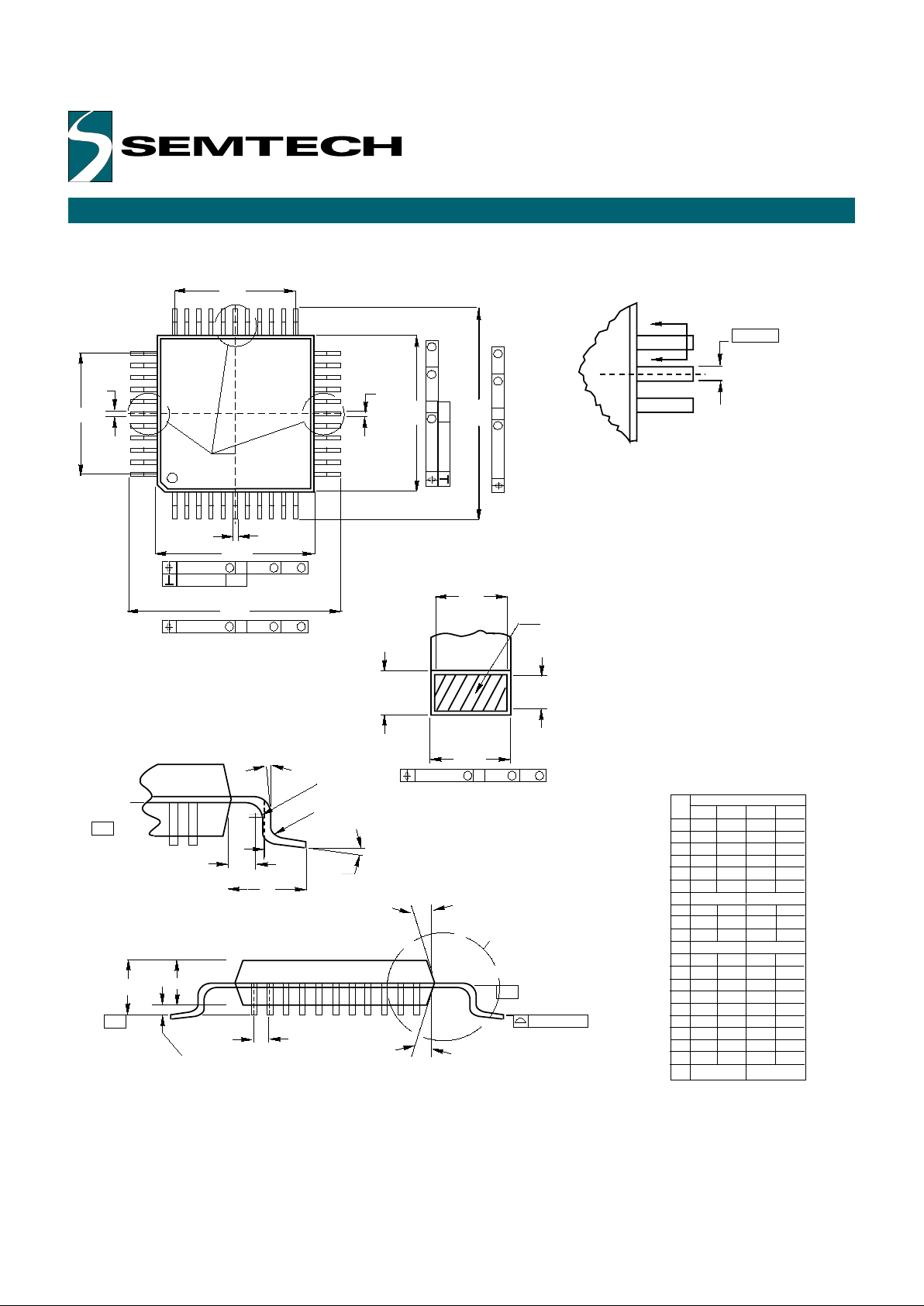
Notes:
1. Positional tolerance of leads (D) shall be
within 0.25 mm (0.010) at maximum material
condition, in relation to the seating plane and
each other.
2. Diminsion L is to the center of the leads when
the leads are formed parallel.
3. Dimension B does not include mold flash.
B
C
D
F
G
H
J
K
L
M
N
13.72
14.22
0.540
0.560
3.94
5.08 0.155 0.200
0.36
0.56 0.014
0.022
1.02
1.52 0.040 0.060
2.54 BSC 0.100 BSC
2.16 0.085
0.20 0.008
2.92 0.015
15 0 15
0.51
1.02 0.020 0.040
MIN MAX
MIN MAX
MILLIMETERS INCHES
DIM
0
0
0
A 51.69 52.45
2.035
2.065
0.38
0.015
0.1353.43
15.24 BSC 0.600 BSC
0
1.65
0.065
0

Copyright Semtech, 1997-2001
DOC5-FJL-DS-106
www.semtech.com
17
MECHANICALS FOR THE UR5HCFJL-FN
W
Y BRK
D
D
V
N
M
L
1
(Note 1) 44
44
Leads
PLCC
P
+
+
Z
G
G1
C
A
R
E
J
44
(Note 1)
Detail S
G1
X
Note 1
U
Z1
B
A
B
C
E
F
G
H
J
K
R
U
V
W
X
Y
Z
G1
K1
Z1
17.40 17.65
0.685
0.695
17.40
17.65 0.685 0.695
4.20 4.57 0.165 0.180
2.29 2.79 0.090 0.110
0.33 0.48 0.013 0.019
1.27 BSC 0.050 BSC
0.66 0.81 0.026 0.032
0.51 - 0.020 -
0.64 - 0.025 -
16.51 16.66 0.650 0.656
16.51 16.66 0.650 0.656
1.07
1.21 0.042 0.048
- 0.50 - 0.020
2 10 2 10
15.50 16.00 0.610 0.630
1.02 - 0.040 -
2 10 2 10
MIN
MAX MIN MAX
MILLIMETERS INCHES
1.07 1.21 0.042 0.048
1.07 1.42 0.042 0.056
DIM
00
0
0
0
00
K1
K
F
H
0.18 (0.007)
0.18 (0.007)TT
-
LSMSNSP
S
LSM
S
NSP
S
0.18 (0.007)
0.18 (0.007)TT
-
LSMSNSP
S
LSM
S
NSP
S
0.18 (0.007) T L
SMS
NSP
S
0.18 (0.007) T LSM
S
NSP
S
0.18 (0.007) T-LSMSNSP
S
0.25 (0.010) T-LSMSNSP
S
Seating Plane
T
0.010 (0.004)
0.18 (0.007) T-LSMSNSP
S
Notes:
1. Due to space limitation, the chip
is represented by a general (smaller)
case outline drawing rather than
showing all 44 leads.
2. Datums L, M, N, and P determine where
the top of the lead shoulder exits plastic
body at mold parting line
3. DIM G1, true position to be measured
at Datum T, Seating Plane
4. DIM R and U do not include mold
protusion. Allowable mold protusion is
0.25 (0.010) per side.
5. Dimensioning and tolerancing per Ansi
Y14.5M, 1982
6. Controlling dimension: Inch
Detail S
M
M
M
M
0.25 (0.010) T
-
LSM
S
NSP
S
--
-
-
M
-
-
-
M
-
M
--
M
-
-
-
View D-D
M
-
M
Copyright Semtech, 1997-2001
DOC5-FJL-DS-106
www.semtech.com
18
MECHANICALS FOR THE UR5HCFJL-FB
Detail A
M
Q
W
K
X
T
R
C
Datum
Plane
Detail C
L
B
A
L
B
V
D
A
S
C
E
G
M
M
H
Seating
Plane
H
Datum
Plane
A,B,D
0.20 (0.008) C
A-B
S
D
S
M
0.05 (0.002) A-B
0.20 (0.008) H
A-B
S
D
S
M
0.20 (0.008) H
A-B
S
D
S
M
0.20 (0.008) C
A-B
S
D
S
M
0.05 (0.002) A-B
0.01 (0.004)
B
C
D
E
F
G
H
J
K
L
M
N
Q
R
S
T
U
V
X
9.90 10.10
0.390
0.398
2.10
2.45 0.083 0.096
0.30 0.45 0.012 0.018
2.00 2.10 0.079 0.083
0.30 0.40 0.012 0.016
0.80 BSC 0.031 BSC
0.25 0.010
0.13
-
0.005
0.65
-
0.026
-
5 10 5 10
0.13
0.17 0.005 0.007
13.45 0.530
0.13 0.005
0
0
0.510
0.40 0.016
MIN MAX MIN MAX
MILLIMETERS INCHES
0 7 0 7
0.13 .30 0.005 0.012
DIM
0
0
0
0
0
0
0
JN
F
Base Metal
D
0.20 (0.008) C
A-B
S
D
S
M
Section B-B
A 9.90 10.10
0.390
0.398
0.23
0.009
0.0370.95
8.00 REF 0.315 REF
12.95 0.510
0
0
0
W
12.95
1.6 REF
13.45
0.530
0.063 REF
Notes
1. Dimensioning and tolerancing per Ansi
Y14.5-M, 1982
2. Controlling dimension: Millimeter
3. Datum Plane "H" is located at the
bottom of the lead and is coincident
with the lead where the lead exits
the plastic body at the bottom of the
parting line.
4. Datums -A-, -B-, and -D- to be determined
at Datum Plane -H-.
5. Dimensions S and V to be determined
at seating plane -C-.
6. Dimensions A and B do not include
Mold protusion. Allowable protusion
is 0.25 (0.010) per side. Dimensions
A and B do include mold mismatch
and are determined at Datum Plane -H-.
7. Dimension D does not include Danbar
protrusion. Allowable Danbar
protrusion is 0.08 (0.003) total in
excess of the D dimension
at Maximum Material Condition.
Danbar cannot be located on the
lower radius or the foot.
--
-
--
B
Detail A
Detail C
1
12
22
11
34
44
33 23
H

Copyright Semtech, 1997-2001
DOC5-FJL-DS-106
www.semtech.com
19
ELECTRICAL SPECIFICATIONS
Absolute Maximum Ratings
Ratings Symbol Value Unit
Supply Voltage Vdd -0.3 to +7.0 V
Input Voltage Vin Vss -0.3 to Vdd +0.3 V
Current Drain per Pin I 25 mA
(not including Vss or Vdd)
Operating Temperature TA T low to T high °C
UR5HCFJL-XX -40 to +85
Storage Temperature Range Tstg -65 to +150 °C
Thermal Characteristics
Characteristic Symbol Value Unit
Thermal Resistance Tja °C per W
Plastic DIP 60
Plastic PLCC 70
DC Electrical Characteristics (Vdd=5.0 Vdc +/-10%, Vss=0 Vdc, Temperature range=T low to T high unless otherwise noted)
Characteristic Symbol Min Typ Max Unit
Output Voltage (I load<10µA) Vol 0.1 V
Voh Vdd–0.1
Output High Voltage (I load=0.8mA) Voh Vdd–0.8 V
Output Low Voltage (I load=1.6mA) Vol 0.4 V
Input High Voltage Vih 0.7xVdd Vdd V
Input Low Voltage Vil Vss 0.2xVdd V
User Mode Current Ipp 5 3.5
mA
Data Retention Mode (0 to 70
°C) Vrm 2.0 V
Supply Current* Idd
Run 2.5 3.5 mA
Wait 0.8 1.5 mA
Start 2.0 50 µA
I/O Ports Hi-Z Leakage Current Iil +/-10 µA
Input Current Iin +/- 1 µA
I/O Port Capacitance Cio 8 12 pF
*In a typical application circuit, including external A/D.
Control Timing (Vdd=5.0 Vdc +/-10%, Vss=0 Vdc, Temperature range=T low to T high unless otherwise noted)
Characteristic Symbol Min Max Unit
Frequency of Operation fosc MHz
Crystal Option 2.0
External Clock Option dc 2.0
Crystal Oscillator Startup Time fop MHz
Crystal (fosc/2) 2.0
External Clock Option dc 2.0
Cycle Time tcyc 1000 ns
Crystal Oscillator Startup Time toxov 100 ms
Stop Recovery Startup Time tiLCH 100 ms
Reset Pulse Width tRL 8 tcyc
Interrupt Pulse Width Low tLIH 125 ns
Interrupt Pulse Period tiLIL
*tcyc
OSC1Pulse Width tOH,
TOL
90 ns
*The minimum period tiLIL should not be less than the number of cycle times it takes to execute the interrupt service routine plus 21 tcyc.

Copyright Semtech, 1997-2001
DOC5-FJL-DS-106
www.semtech.com
20
For sales information
and product literature,
contact:
HID & System Mgmt Division
Semtech Corporation
568 Broadway
New York, NY 10012
hidinfo@semtech.com
http://www.semtech.com
212 226 2042 Telephone
212 226 3215 Telefax
Semtech Western Regional Sales
805-498-2111 Telephone
805-498-3804 Telefax
Semtech Central Regional Sales
972-437-0380 Telephone
972-437-0381 Telefax
Semtech Eastern Regional Sales
203-964-1766 Telephone
203-964-1755 Telefax
Semtech Asia-Pacific Sales Office
+886-2-2748-3380 Telephone
+886-2-2748-3390 Telefax
Semtech Japan Sales Office
+81-45-948-5925 Telephone
+81-45-948-5930 Telefax
Semtech Korea Sales Sales
+82-2-527-4377 Telephone
+82-2-527-4376 Telefax
Northern European Sales Office
+44 (0)2380-769008 Telephone
+44 (0)2380-768612 Telefax
Southern European Sales Office
+33 (0)1 69-28-22-00 Telephone
+33 (0)1 69-28-12-98 Telefax
Central European Sales Office
+49 (0)8161 140 123 Telephone
+49 (0)8161 140 124 Telefax
Copyright 2000-2001 Semtech Corporation. All rights reserved.
KeyCoder, GreenCoder, Zero-Power and Self-Power Management
are trademarks of Semtech Corporation. Semtech is a registered
trademark of Semtech Company. All other trademarks belong to
their respective companies.
INTELLECTUAL PROPERTY DISCLAIMER
This specification is provided "as is" with no warranties whatsoever
including any warranty of merchantability, fitness for any particular
purpose, or any warranty otherwise arising out of any proposal,
specification or sample. A license is hereby granted to reproduce
and distribute this specification for internal use only. No other
license, expressed or implied to any other intellectual property
rights is granted or intended hereby. Authors of this specification
disclaim any liability, including liability for infringement of proprietary
rights, relating to the implementation of information in this
specification. Authors of this specification also do not warrant or
represent that such implementation(s) will not infringe such rights.
 Loading...