

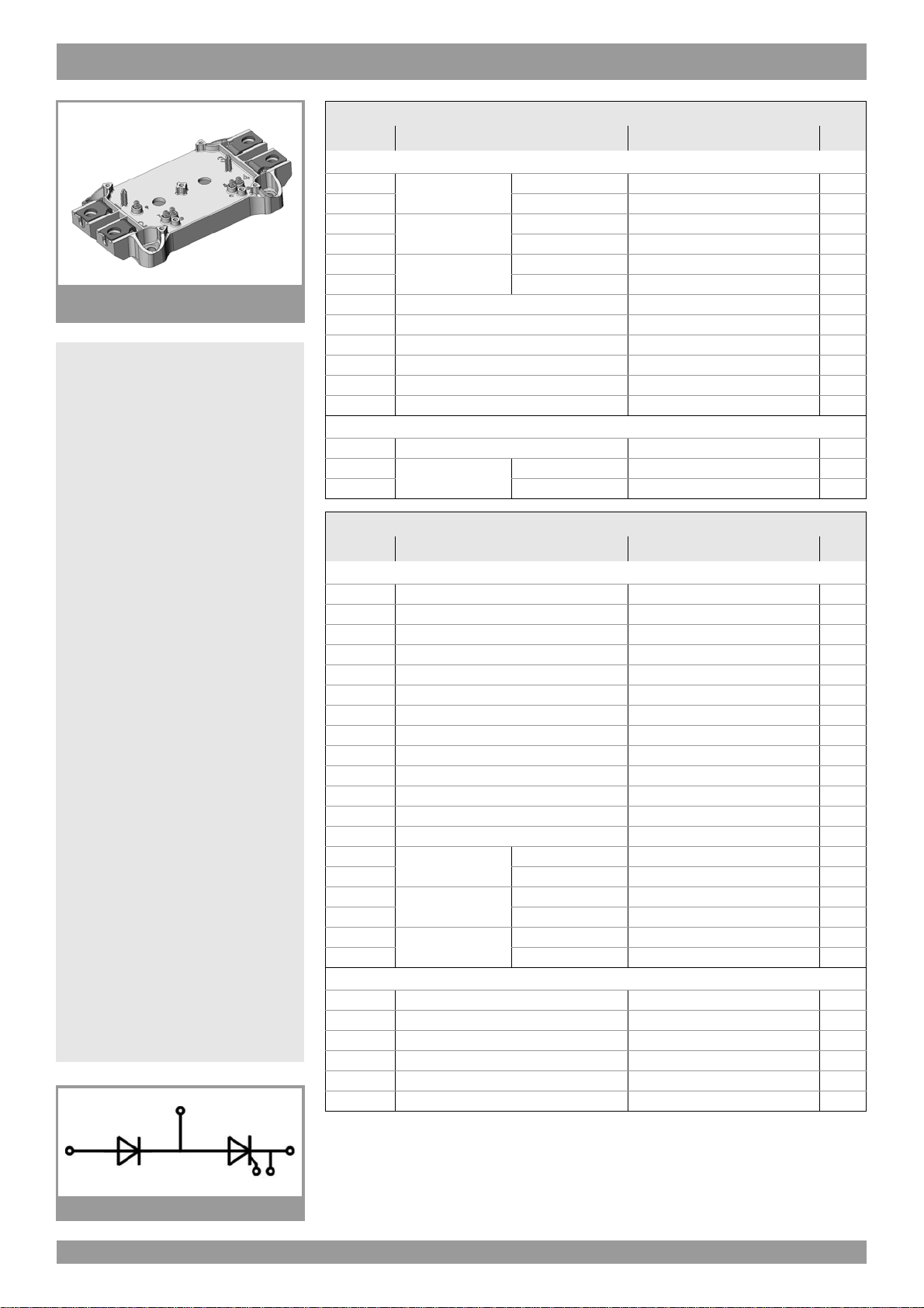
SEMiX302KH16s
SEMiX® 2s
Rectifier Thyr./Diode Module
SEMiX302KH16s
Features
• Terminal height 17 mm
• Chips soldered directly to isolated
substrate
Typical Applications*
• Input Bridge Rectifier for AC/DC motor
control
• Power supply
Absolute Maximum Ratings
Symbol Conditions Values Unit
Chip
=85°C
I
T(AV)
I
TSM
2
t
i
V
RSM
V
RRM
V
DRM
(di/dt)
(dv/dt)
T
j
cr
cr
sinus 180°
10 ms
10 ms
Tj= 130 °C
Tj= 130 °C
T
c
T
= 100 °C
c
T
=25°C
j
T
= 130 °C
j
T
=25°C
j
T
= 130 °C
j
300 A
230 A
9300 A
8000 A
432000 A
320000 A
1700 V
1600 V
1600 V
130 A/µs
1000 V/µs
-40 ... 130 °C
2
s
2
s
Module
T
stg
V
isol
AC sinus 50Hz
1min
1s
-40 ... 125 °C
4000 V
4800 V
Characteristics
Symbol Conditions min. typ. max. Unit
Chip
V
T
V
T(TO)
r
T
I
DD;IRD
t
gd
t
gr
t
q
I
H
I
L
V
GT
I
GT
V
GD
I
GD
R
th(j-c)
R
th(j-c)
R
th(j-c)
Tj=25°C, IT= 900 A
Tj= 130 °C
Tj= 130 °C
Tj= 130 °C, VDD = V
DRM
; VRD = V
Tj=25°C, IG=1A, diG/dt = 1 A/µs
VD = 0.67 * V
DRM
Tj= 130 °C
Tj=25°C
Tj=25°C, RG=33Ω
Tj=25°C, d.c.
Tj=25°C, d.c.
Tj= 130 °C, d.c.
Tj= 130 °C, d.c.
per thyristor
per module
sin. 180°
per thyristor
per module
per thyristor
per module
RRM
1.7 V
0.85 V
1.1 mΩ
75 mA
1µs
2µs
150 µs
150 500 mA
300 1000 mA
3V
200 mA
0.25 V
10 mA
K/W
K/W
0.091 K/W
0.091 K/W
K/W
K/W
Module
R
th(c-s)
per chip K/W
per module 0.045 K/W
M
s
M
t
a 5 * 9,81 m/s
to heat sink (M5) 3 5 Nm
to terminals (M6) 2.5 5 Nm
2
w250g
KH
© by SEMIKRON Rev. 34 – 25.03.2010 1
SEMiX302KH16s
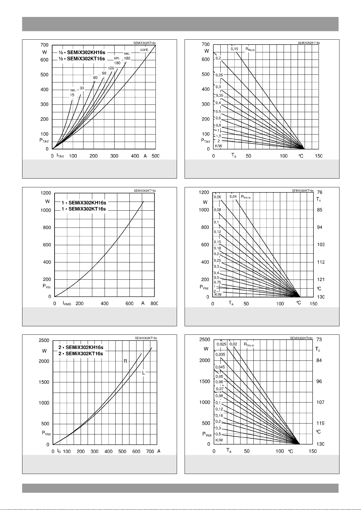
Fig. 1L: Power dissipation per thyristor/diode vs.
on-state current
Fig. 2L: Power dissipation of one module vs. rms current
Fig. 1R: Power dissipation per thyristor/diode vs.
ambient temperature
Fig. 2R: Power dissipation of one module vs. case
temperature
Fig. 3L: Power dissipation of two modules vs. direct
current
2 Rev. 34 – 25.03.2010 © by SEMIKRON
Fig. 3R: Power dissipation of two modules vs. case
temperature

SEMiX302KH16s
Fig. 4L: Power dissipation of three modules vs. direct
current
Fig. 5: Recovered charge vs. current decrease Fig. 6: Transient thermal impedance vs. time
Fig. 4R: Power dissipation of three modules vs. case
temperature
Fig. 7: On-state characteristics Fig. 8: Surge overload current vs. time
© by SEMIKRON Rev. 34 – 25.03.2010 3

SEMiX302KH16s
Fig. 9: Gate trigger characteristics
spring configuration
SEMiX 2s
This is an electrostatic discharge sensitive device (ESDS), international standard IEC 60747-1, Chapter IX
* The specifications of our components may not be considered as an assurance of component characteristics. Components have to be tested
for the respective application. Adjustments may be necessary. The use of SEMIKRON products in life support appliances and systems is
subject to prior specification and written approval by SEMIKRON. We therefore strongly recommend prior consultation of our personal.
4 Rev. 34 – 25.03.2010 © by SEMIKRON
 Loading...