

Semelab Plc IP3843N, IP3843J, IP3843D-8, IP3843D-14, IP3843D Datasheet
...
IP1842 SERIES
IP1843 SERIES
Prelim.3/00
Semelab plc. Telephone +44(0)1455 556565. Fax +44(0)1455 552612.
E-mail: sales@semelab.co.uk
Website: http://www.semelab.co.uk
CURRENT MODE
REGULATING
PULSE WIDTH
MODULATORS
FEATURES
• Guaranteed ±1% reference voltage tolerance
• Guaranteed ±10% frequency tolerance
• Low start–up current (<500
mmmmA)
• Under voltage lockout with hysteresis
• Output state completely defined for all supply
and input conditions
• Interchangeable with UC1842 and UC1843
series for improved operation
• 500kHz operation
V
CC
Supply Voltage (low impedance source)
(ICC< 30mA)
I
O
Output Current
Output Energy (capacitive load)
Analog Inputs (pins 2 and 3)
Error Amp Output Sink Current
P
D
Power Dissipation T
amb
= 25°C
Derate @ T
amb
> 50°C
P
D
Power Dissipation T
case
= 25°C
Derate @ T
case
> 25°C
T
STG
Storage Temperature Range
T
L
Lead Temperature (soldering, 10 seconds)
+30V
Self limiting
±1A
5mJ
–0.3V to +V
CC
10mA
1W
10mW/°C
2W
24mW/°C
–65 to 150°C
+300°C
ABSOLUTE MAXIMUM RATINGS (T
case
= 25°C unless otherwise stated)
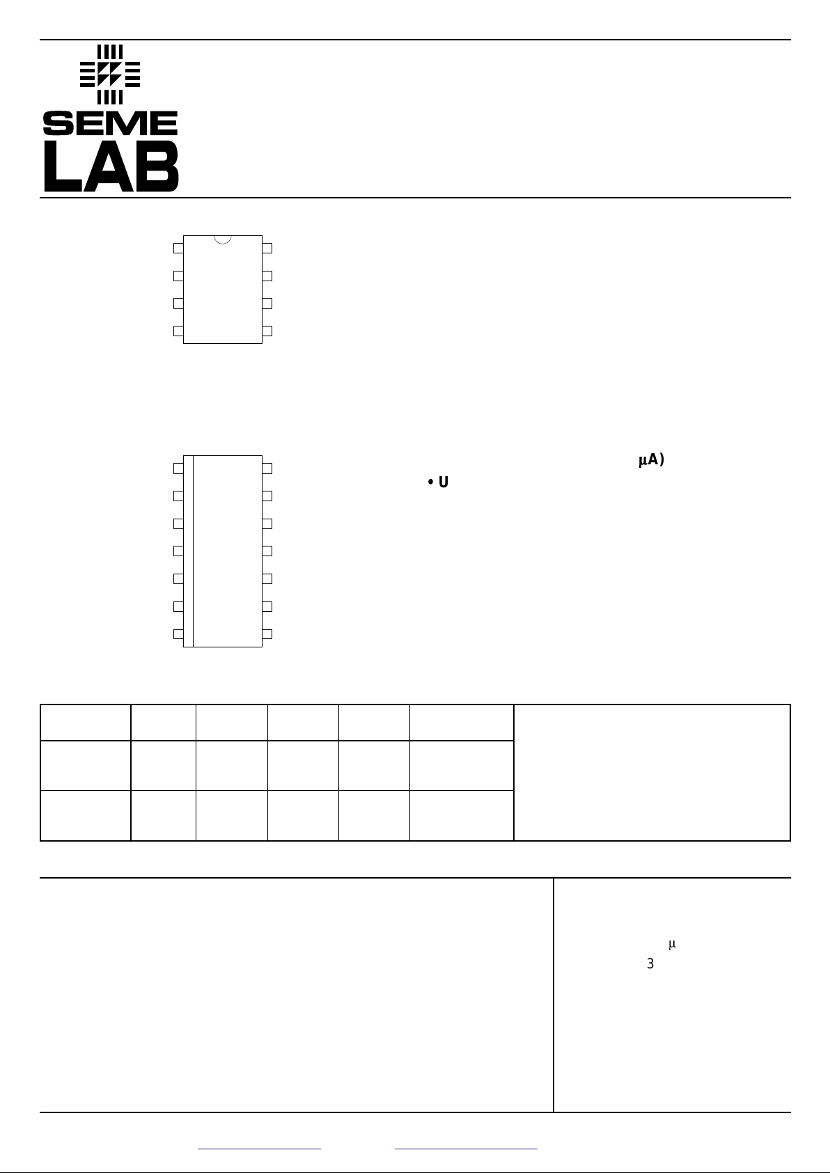
TOP VIEW
J Package – 8 Pin Ceramic DIP
N Package – 8 Pin Plastic DIP
D-8 Package – 8 Pin Plastic (150) SOIC
1
2
3
4
8
7
6
5
COMP
V
REF
GROUND
OUTPUT
RT/C
T
V
CC
I
SENSE
V
FB
TOP VIEW
D-14 Package – 14 Pin Plastic (150) SOIC
COMP
V
REF
GROUND
OUTPUT
1
2
3
4
POWER
GROUND
5
6
7
14
13
12
11
10
9
8
N/C
R
T/CT
I
SENSE
N/C
N/C N/C
V
CC
V
FB
V
C
Part J–Pack N–Pack D–8D–14 Temp.
Number 8 Pin 8 Pin 8 Pin 14 Pin Range
IP1842 ✔ -55 to +125°C
IP2842 ✔✔✔✔-25 to +85°C
IP3842 ✔✔✔✔0 to +70°C
IP1843 ✔ -55 to +125°C
IP2843 ✔✔✔✔-25 to +85°C
IP3843 ✔✔✔✔0 to +70°C
Order Information
Note:
To order, add the package identifier to the
part number.
eg. IP1842J
IP3843D-14
IP1842 SERIES
IP1843 SERIES
Prelim.3/00
Semelab plc. Telephone +44(0)1455 556565. Fax +44(0)1455 552612.
E-mail: sales@semelab.co.uk
Website: http://www.semelab.co.uk
DESCRIPTION
The IP1842 and IP1843 series of switching regulator control circuits contain all the functions necessary to
implement off–line, current mode switching regulators, using a minimum number of exter nal parts. Functions
included are voltage reference, error amplifier, current sense comparator, oscillator, totem pole output driver and
under-voltage lockout circuitry.
Although pin compatible with the UC1842 and 1843 series, SEMELAB has incorporated several improvements in
the IP1842 and IP1843 series allowing tighter and more complete specification of electrical performance.
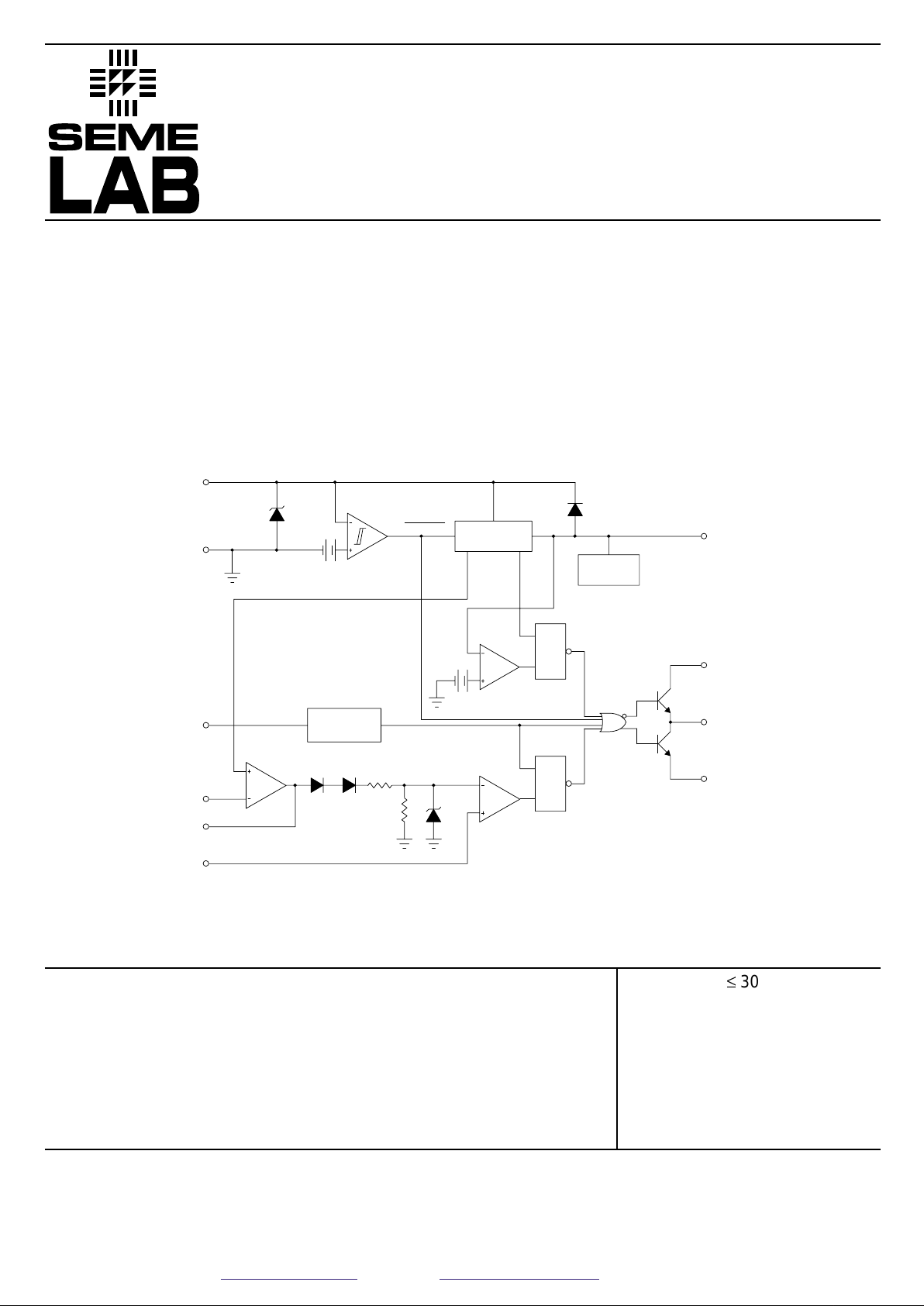
BLOCK DIAGRAM
Values in brackets are for IP1843 series.
3.6V
ERROR
AMP
OSCILLATOR
2R
R
1V
R
S
PWM
LATCH
CURRENT
SENSE
COMPARATOR
16V
(8.4V)
6V
(0.5 V) 2.5 V
UNDER–VOLTAGE
LOCKOUT
ENABLE
REFERENCE
REGULATOR
5V
INTERNAL
BIAS
34V
REG
R
S
V STATUS
LATCH
REF
OUTPUT
V
REF
C
OMP
G
ND
V
CC
I
SENSE
V
FB
/CR
TT
POWER
GROUND
V
C
PIN NUMBERS
1st Number
2nd Number
– N, J and 8 Pin D Packages
– 14 Pin D Package.
3/5
5/9
7/12
2/3
1/1
4/7
6/10
7/11
5/8
8/14
V
CC
Supply Voltage
1
I
O
Output Current
Analog Inputs (pins 2 and 3)
Error Amp Output Sink Current
IP1842 , IP1843
Operating Ambient Temperature Range IP2842 , IP2843
IP3842 , IP3843
£
30V
0 to ±200mA
–0.3V to 3V
0 to 2mA
–55 to 125°C
–25 to 85°C
0 to 70°C
Notes:
1. Lower limit set by under voltage lockout specification.
RECOMMENDED OPERATING CONDITIONS
 Loading...