

Semelab Plc IP3524J, IP3524D, IP2524D, IP2524N, IP2524J Datasheet
...
LAB
SEME
IP1524 SERIES
Semelab plc. Telephone (01455) 556565. Telex: 341927. Fax (01455) 552612.
Prelim. 3/95
REGULATING
PULSE WIDTH
MODULATORS
FEATURES
• Guaranteed ±2% reference voltage tolerance
• Guaranteed ±6% oscillator tolerance
• Fully specified temperature performance
• Guaranteed 10mV/1000 hours long term stability
• Interchangeable with SG1524 series
+V
IN
Input Voltage
Collector Voltage
Output Current (each transistor)
Reference Load Current
Oscillator Charging Current
Shut Down Pin Voltage
Current Limit Sense Common Mode Range
P
D
Power Dissipation TA= 25°C
Derate @ TA> 50°C
P
D
Power Dissipation TC= 25°C
Derate @ TC> 25°C
T
J
Operating Junction Temperature
T
STG
Storage Temperature Range
T
L
Lead Temperature (soldering, 10 seconds)
+40V
+40V
100mA
Internally Limited
5mA
+5.5V
–1.0 to +1.0V
1W
10mW/°C
2W
16mW/°C
See Ordering Information
–65 to +150°C
+300°C
ABSOLUTE MAXIMUM RATINGS (T
case
= 25°C unless otherwise stated)
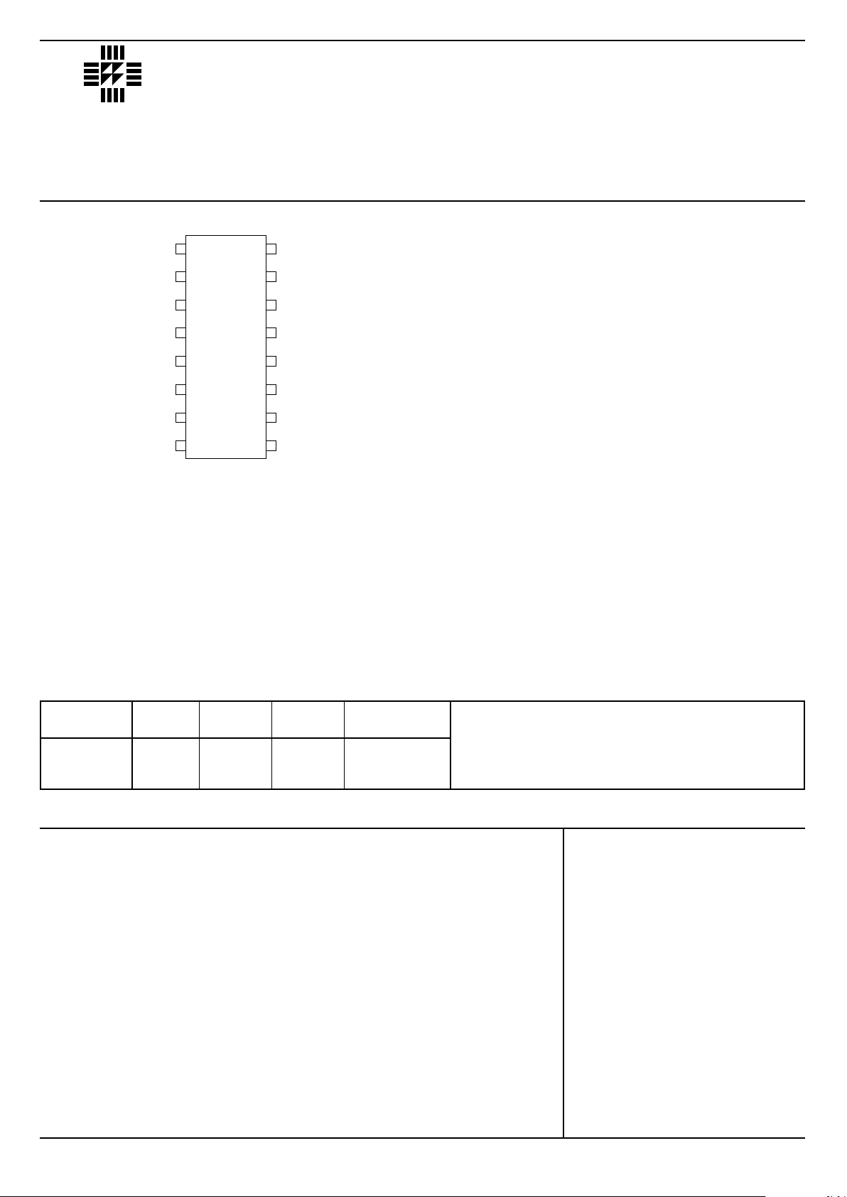
TOP VIEW
J Package – 16 Pin Ceramic DIP
N Package – 16 Pin Plastic DIP
D Package – 16 Pin Plastic (150) SOIC
8
1
2
3
4
5
6
7
14
13
12
11
10
9
15
16
INV. IN P UT
N. I. INPUT
OSC. OUTPUT
+C.L. SENSE
–C.L. SE NSE
R
T
C
T
GROUND
V
REF
V
IN
E
B
C
B
C
A
E
A
SHUTDOWN
COMPENSATION
Part J–Pack N–Pack D–16 Temp.
Number 16 Pin 16 Pin 16 Pin Range
IP1524 ✔ -55 to +125°C
IP2524 ✔✔✔-25 to +85°C
IP3524 ✔✔✔0 to +70°C
Order Information
Note:
To order, add the package identifier to the part number.
eg. IP1524J
IP3524D–16
LAB
SEME
IP1524 SERIES
Semelab plc. Telephone (01455) 556565. Telex: 341927. Fax (01455) 552612.
Prelim. 3/95
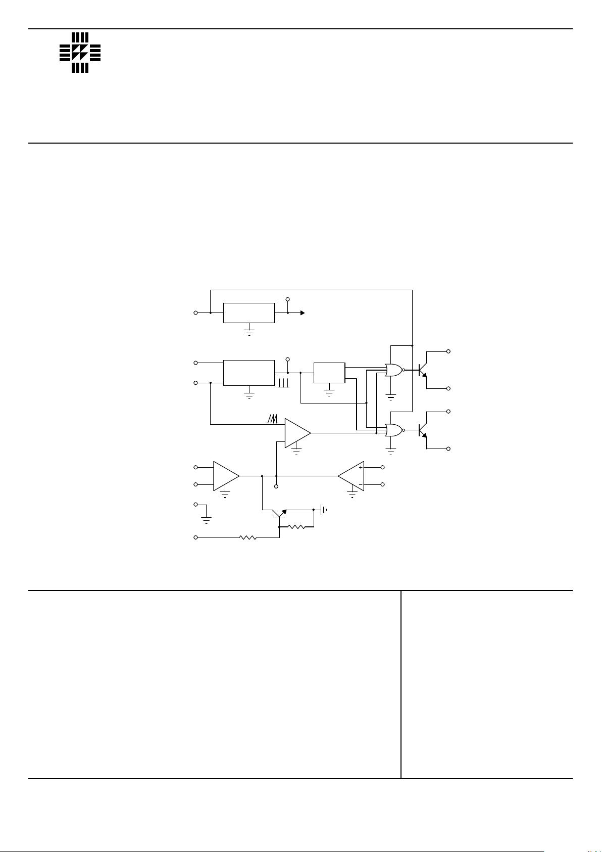
V
R
C
+5V TO ALL
INTERNAL CIRCUITRY
INV.
INPUT
ERROR
AMP
REFERENCE
REGULATOR
OSCILLATOR
OSCILLATOR
OUTPUT
FLIP
FLOP
COMPARATOR
+5V
NOR
NOR
SHUTDOWN
C
E
C
E
+5V
C.L.
N.I.
INPUT
GND
(SUBSTRATE)
COMPENSATION
+SENSE
–SENSE
+5V
4
9
5
1
2
8
10
IN
T
T
15
6
7
A
A
B
B
12
11
13
14
16
3
1k
Ω
10k
Ω
+8 to +40V
0 to +40V
+1.8 to +3.4V
0 to 100mA
0 to 20mA
30µA to 2mA
50Hz to 500kHz
1.8kΩ to 100kΩ
1nF to 0.1µF
–55 to +125°C
-25 to +85°C
0 to +70°C
RECOMMENDED OPERATING CONDITIONS
DESCRIPTION
The IP1524 series of PWM switching regulator control circuits contains all the functions required to implement singleended or push-pull switching regulators. Included are voltage reference, error amplifer, oscillator, PWM comparator,
output drivers, current limiting and shutdown circuitry.
Although functionally indentical to the SG1524 series, SEMELAB has incorporated several improvements to the IP1524
allowing tighter and more complete specification of electrical performance.
BLOCK DIAGRAM
V
IN
Input Voltage
Collector Voltage
Error Amp Common Mode Range
Output Current (each transistor)
Reference Load Current
Oscillator Charging Current
Oscillator Frequency Range
R
T
Oscillator Timing Resistor
C
T
Oscillator Timing Capacitor
T
AMB
Operating Ambient Temperature Range IP1524
IP2524
IP3524
 Loading...