

Seme BUL53BSMD Datasheet

BUL53BSMD
Semelab plc. Telephone +44(0)1455 556565. Fax +44(0)1455 552612.
E-mail: sales@semelab.co.uk
Website: http://www.semelab.co.uk
Prelim. 7/00
V
CBO
Collector – Base Voltage
V
CEO
Collector – Emitter Voltage (IB= 0)
V
EBO
Emitter – Base Voltage (IC= 0)
I
C
Collector Current
I
C(PK)
Peak Collector Current
I
B
Base Current
P
D
Power Dissipation
R
?
Thermal Impedance (when mounted on thermally conducting PCB)
T
j
Maximum Junction Temperature
T
stg
Storage Temperature Range
500V
250V
10V
12A
20A
3A
60W
3.0°C/W
200°C
–55 to +200°C
MECHANICAL DATA
Dimensions in mm
)
)
ADVANCED DISTRIBUTED
BASE DESIGN
HIGH VOLTAGE, HIGH SPEED NPN
SILICON POWER TRANSISTOR
SMD1
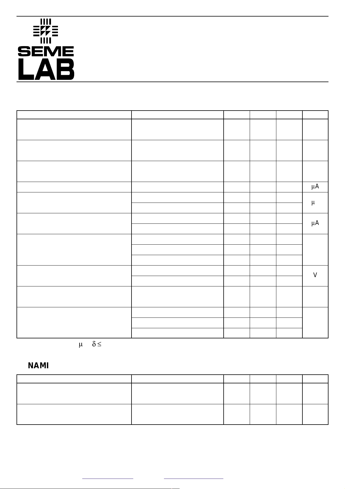
ABSOLUTE MAXIMUM RATINGS (T
case
= 25°C unless otherwise stated)
FEATURES
• Multi-Base design for efficient energy
distribution across the chip.
• SIgnificantly improved switching and energy
ratings across full temperature range.
• Ion implant and high accuracy masking for
tight control of characteristics from batch to
batch.
• Triple guard rings for improved control of
high voltages.
• CERAMIC SURFACE MOUNT PACKAGE
• FULL MIL/AEROSPACE TEMPERATURE
RANGE
• SCREENING OPTIONS FOR MILITARY AND
SPACE APPLICATIONS
• SEMEFAB DESIGNED AND DIFFUSED DIE
• HIGH VOLTAGE (V
CBO
= 800V)
• FAST SWITCHING (t
f
= 100ns)
• HIGH ENERGY RATING
Pad 1 – Base Pad 2 – Collector Pad 3 – Emitter
0.89
(0.035)
min.
3.70 (0.146)
3.41 (0.134)
4.14 (0.163)
3.84 (0.151)
min.
0.76
(0.030)
3.70 (0.146)
3.41 (0.134)
13
3.60 (0.142)
Max.
10.69 (0.421)
10.39 (0.409)
2
9.67 (0.381)
9.38 (0.369)
11.58 (0.456)
11.28 (0.444)
16.02 (0.631)
15.73 (0.619)
0.50 (0.020
0.26 (0.010
BUL53BSMD
Semelab plc. Telephone +44(0)1455 556565. Fax +44(0)1455 552612.
E-mail: sales@semelab.co.uk
Website: http://www.semelab.co.uk
Prelim. 7/00
Parameter Test Conditions Min. Typ. Max. Unit
Parameter Test Conditions Min. Typ. Max. Unit
IC= 100mA
I
C
= 1mA
I
B
= 1mA IC= 0
I
B
= 0 VCE= 250V
I
E
= 0 VCB= 500V
T
C
= 125°C
I
C
= 0 VEB= 5V
T
C
= 125°C
I
C
= 100mA IB= 10mA
I
C
= 2A IB= 200mA
I
C
= 5A IB= 500mA
I
C
= 2A IB= 200mA
I
C
= 5A IB= 500mA
I
C
= 1A VCE= 4V
I
C
= 100mA VCE= 4V
I
C
= 2A VCE= 4V
I
C
= 5A VCE= 4V
ELECTRICAL CHARACTERISTICS (T
case
= 25°C unless otherwise stated)
Collector - Emitter
sustaining voltage
Collector - Base
breakdown voltage
Emitter - Base
breakdown voltage
Collector cut-off current
Collector - Base cut-off
current
Emitter cut-off current
Collector - Emitter
saturation voltage
Base - Emitter
saturation voltage
Base - Emitter
saturation voltage
DC Current gain
250
500
10
100
10
100
10
100
0.05 0.1
0.15 0.3
0.3 0.6
0.8 1.1
0.9 1.2
0.8 1.0
20 45
20 40
20
V
V
V
m
A
m
A
m
A
V
V
V
—
Transition frequency
Output capacitance
I
C
= 100mA VCE= 4V
f = 10MHz
V
CB
= 20V IE = 0
f = 1.0MHz
20
200
MHz
pF
* Pulse test tp= 300ms ,
d £
2%
DYNAMIC CHARACTERISTICS (T
case
= 25°C unless otherwise stated)
V
CEO(sus)*
V
(BR)CBO*
V
(BR)EBO*
I
CEO*
I
CBO*
I
EBO*
V
CE(sat)*
V
BE(sat)*
V
BE(on)*
h
FE*
f
T
C
ob
 Loading...