

Page 1

SERVICE
MANUAL
HD/HR RANGE
OF SERVOMOTORS
ISSUE 2
WARNING
Servomotors contain magnetic
material which will attract metal
particles. Care should be taken
when dismantling motors to
avoid this.
All D.C. servomotors
manufactured by SEM contain
magnets which are air stable
and can be dismantled without
demagnetisation
Page 2

HD/HR55
servicing instructions
1 GENERAL
1.1 Before starting work on the motor, these servicing instructions should
be read and fully understood.
1.2 Servicing of SEM motors must be done only by suitably trained and
qualified personnel, and only after such motors have been electrically
isolated and removed from their mechanical drives.
1.3 The jaws of any vice or clamp must be suitably protected when used to
grip any part of the motor.
1.4 When separating the motor end covers from the motor body, care must
be taken to avoid damage to their mating surfaces.
1.5 NOTE. There are strong magnetic forces between the stator and
the rotor of all SEM servomotors. Fingers should be kept clear of
the gaps between the stator and end covers during assembly and
disassembly of the rotor.
1.6 Dismantled components awaiting reassembly should be kept in a safe,
clean and dry location.
Various types of encoder are used, involving different procedures
for dismantling, reassembly, connection, setting up and testing.
Contact SEM with regard to relevant servicing procedures for the
particular type of encoder involved.
2 MARKING
2.1 The following relationships must be marked with a marker pen or other
suitable method before dismantling.
2.2 Drive end (DE) cover (A) to motor body (B).
2.3 Non-drive end cover (D) to motor body (C).
2.4 Enclosing Cover (18) to non-drive end (NDE) cover (17).
2.5 Prior to resolver dismantling, mark outside end faces of resolver stator
(4) and resolver rotor (3)
3 DISMANTLING THE MOTOR
3.1 Remove 4 M4 socket screws from N.D.E. enclosing cover (18), remove
the end cover and the gasket.
3.2 Remove 8 screws (21) from D.E. cover (12).
3.3 For Sagem resolver this must be removed prior to dismantling of the
motor, proceed as per instructions for tacho removal, for any other
manufacturer check with SEM for instructions.
3.4 Withdraw D.E. cover with complete attached assembly of rotor (1),
bearings (10 & 8), resolver rotor (3) and spacer (5). Remove circlip
(11) and press out rotor shaft to separate from D.E. housing. Remove
circlip (9) and remove bearing from D.E. housing. To remove resolver
rotor (3) use bearing extractor tool behind the shoulder on spacer (5);
the bearing can then be withdrawn. Handle the resolver assembly with
great care at all times.
3.5 Before removing N.D.E., go through the disconnection sequence:
3.6 Disconnection sequence. PIN REMOVAL TOOL REQUIRED –
available from SEM Ltd. Both connectors (23 & 27) must be removed
before N.D.E. cover can be removed. Take out 4 screws, pull the
socket forward to allow access to connector pins. Withdraw the
connector pins using the pin removal tool. Pull wires through from
feedback connector (23) to clear screw access; remove 4 screws (20)
from N.D.E. cover. Withdraw the cover carefully to avoid damage to
wiring.
3.7 Removal of resolver. Important: At all stages of removal and
reassembly, the resolver unit must be handled with care. Unscrew (36)
and release resolver body (4) complete. At this point the resolver rotor
(3) is free and will drop out of the resolver body unless held in place by
hand. Remove the resolver and store in a safe place until re-assembly.
3.8 Removal of D.E. cover – Brake Models. Remove 8 cover screws (21)
then 3 screws (19) holding brake assembly. This allows cover to be
removed, leaving the brake and bearing on the shaft and exposing the
leads to the brake. Disconnect these leads and remove complete rotor
assembly as Section 3.4. Pull the bearing off the shaft, leaving brake
free to be removed. When this sequence is complete, continue as
Section 3.4 above.
screws.
4.2 Fit the resolver to the N.D.E. cover with 3 screws and clamping
washers (metal shield outwards), feed both resolver and thermal
overload leads through the hole on the left of the N.D.E. cover.
4.3 Fit 2 connector elbows with cap screws and gaskets, bringing out the
leads at the same time. Press the pins firmly into the back of the
connectors until they click into place. Position the connectors and
gaskets and tighten down with screws and washers.
4.4 Fit O-ring, bearing and circlip to D.E. cover, slide rotor into
cover/bearing assembly. Slide bearing onto N.D.E. of shaft.
4.5 Supporting the inner race of the bearing, press both bearings into
place. Fit spacer and tolerance ring to N.D.E. Fit circlip at D.E.
4.6 Carefully stand motor upright (with N.D.E. down). Locate the wave
washer in the N.D.E. housing, lower the rotor/cover assembly very
carefully into the body and screw the D.E. cover to the body.
4.7 Support and press into position (resolver rotor). Fit a new tolerance
ring (2).
4.8 Fit brake, carefully press rotor into brake (ensuring that teeth line up
correctly). Fit rotor to body as above, but connect and isolate 2 brake
leads before pushing into place.
5 RESETTING THE RESOLVER.
5.1 This only applies to a standard resolver supplied by SEM with the
standard setting. For any other resolver, refer to the drive
manufacturer.
5.2 For these procedures it is necessary to make connections and links to
feedback connector pins. To avoid damage to these pins, it is
advisable to make such connections and links via a suitable separate
test socket which mates with the feedback connector multi-pin plug
(27) and which has short leads connected to its sockets. Alternatively
appropriate pins can be made available for connections and links by
withdrawing them from plug (27) as in Section 3.6 “Disconnection”.
5.3 If a brake is used, it must be temporarily held off during this operation
by applying a 24V dc supply across the brake terminals.
5.4 Undo 4 screws (20) and pull back the enclosing cover (18) to give
access to the resolver. With the above test plug connected to the
feedback connector, link pins R1 to S3 & pins R2 to S2. Connect a
signal generator (approx 5V 6kHz) between pins R1 and R2. Connect
an AC voltmeter between pins S1 and R2.
5.5 At the power connector, link motor phase pins V and W and then
connect a low voltage dc supply to motor phases at power connector
pins U (+ve) and V+W (-ve). Adjust this voltage to give between 25%
and 100% of motor rated current thereby causing the motor to turn to a
preferred position.
5.6 Slacken the 3 screws holding the resolver stator and then rotate it until
the voltmeter gives a maximum reading. Reconnect the AC voltmeter
to pins S4 and R2. Make a small final adjustment of the resolver stator
to get a minimum reading. Retighten the screws, disconnect the test
socket, the supplies, the voltmeter and links, let the brake (if used) be
re-applied.
5.7 Attach the protective shield (if fitted) to the resolver and fix the
enclosing cover (18) to the NDE cover in accordance with marks made
in operation 2.3.
6 ELECTRICAL TESTS NECESSARY BEFORE
CONNECTING MOTOR TO AMPLIFIER.
6.1 Measure motor stator winding resistances U-V, V-W, W-U. These
must be equal to within 3%.
6.2 Check dielectric strength by flash test at 1000 Vac from:
a Phase U (power connector pin) U to motor body.
b Phase U to thermal sensor (feedback connector pins Thermal
Sensor + and Thermal Sensor -).
c Phase U to brake connections (power connector pins B+ & B-).
If flash test is not possible then check that insulation resistance is
greater than 1megaohm.
6.3 Check dielectric strength by flash test at 500Vac or with a 500Vdc
supply from motor body to:
d Brake connections (power connector pins B+ and B-)
e Thermal sensor (feedback connector pins Thermal Sensor + and
Thermal Sensor -)
f Resolver (feedback connector pins R2 and S1.
If flash test is not possible then check that insulation resistance is
greater than 1megaohm.
4 RE-ASSEMBLY OF THE MOTOR
To fit N.D.E. cover to body. Note: new circlips, oil seals and
bearings must be fitted on the re-assembly as standard
procedure.
4.1 Feed the thermal overload leads through the hole in the N.D.E. cover,
feed the earth lead through the hole in the body and fit 4 cap head
SEM Limited, Faraday Way, Orpington, Kent BR5 3QT England
Telephone: +44 (0)1689 884700 ● Fax: +44 (0) 1689 884884
E-mail: info@sem.co.uk ● Internet http://www.sem.co.uk
Page 3
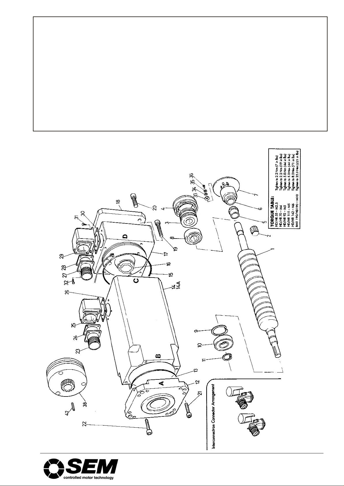
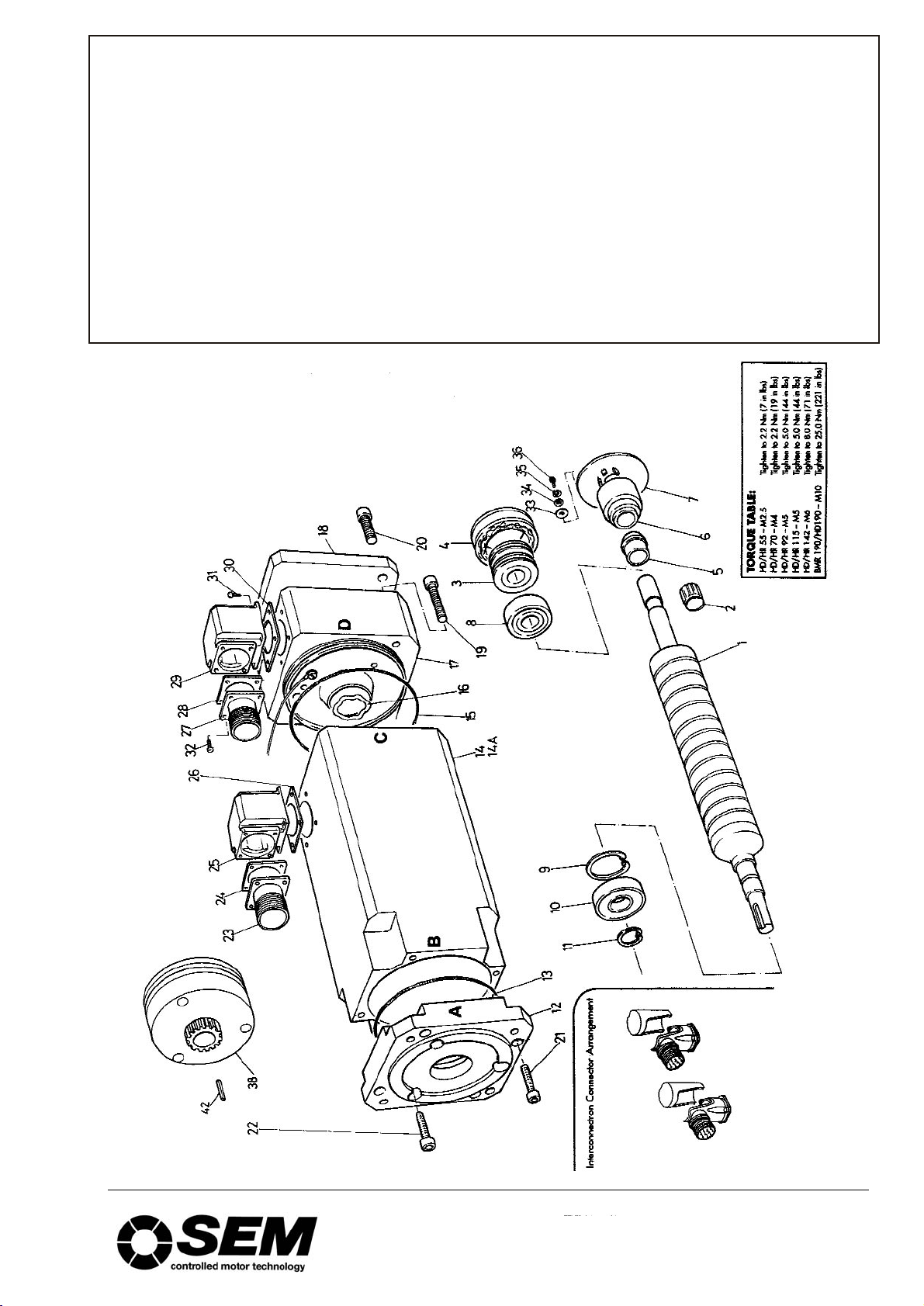
HD/HR55 parts list
ITEM NO. DESCRIPTION
1 Rotor Assembly
2 Tolerance Ring
3 Resolver Rotor
4 Resolver Body
5 Spacer (Non tacho motors only)
6 Tachogenerator Rotor Assembly
7 P.C.B. Assembly
8 N.D.E. Bearing
9 Bearing Retaining Circlip
10 D.E. Bearing
11 Bearing Retaining Circlip
12 D.E. Cover
13 D.E. ‘O’ Ring
14 Motor Body
14a Long Motor Body for Brake Motor
15 N.D.E. ‘O’ Ring
16 Wave Washer
17 Non Drive Encl Housing
18 N.D.E. Enclosing Cover
19 N.D.E. Housing Fixing Screw
20 N.D.E. Cover Fixing Screw
21 D.E. Cover Fixing Screw
22 Fixing Screw: Brake
23 M.S. Connector: Power
24 Gasket
25 Connector Housing
26 Gasket
27 MS Connector: Feedback
28 Gasket
29 Connector Housing
30 Gasket
31 Fixing Screw: Cap-head
32 Fixing Screw: Cheese-head
33 Plain Washer M4
34 Plain Washer M3
35 Single-turn Coil Spring Washer
36 Fixing Screw
37 Brake Key (Optional)
38 Brake (Optional)
SEM Limited, Faraday Way, Orpington, Kent BR5 3QT England
Telephone: +44 (0)1689 884700 ● Fax: +44 (0) 1689 884884
E-mail: info@sem.co.uk ● Internet http://www.sem.co.uk
Page 4

HD/HR70
servicing instructions
1 GENERAL
1.1 Before starting work on the motor, these servicing instructions should
be read and fully understood.
1.2 Servicing of SEM motors must be done only by suitably trained and
qualified personnel, and only after such motors have been electrically
isolated and removed from their mechanical drives.
1.3 The jaws of any vice or clamp must be suitably protected when used to
grip any part of the motor.
1.4 When separating the motor end covers from the motor body, care must
be taken to avoid damage to their mating surfaces.
1.5 NOTE. There are strong magnetic forces between the stator and
the rotor of all SEM servomotors. Fingers should be kept clear of
the gaps between the stator and end covers during assembly and
disassembly of the rotor.
1.6 Dismantled components awaiting reassembly, should be kept in a safe,
clean and dry location.
Various types of encoder are used, involving different procedures
for dismantling, reassembly, connection, setting up and testing.
Contact SEM with regard to relevant servicing procedures for the
particular type of encoder involved.
2 MARKING
2.1 The following relationships must be marked with a marker pen or other
suitable method before dismantling.
2.2 Drive end (DE) cover (A) to motor body (B).
2.3 Non-drive end cover (D) to motor body (C).
2.4 Enclosing Cover (18) to non-drive end (NDE) cover (17).
2.5 Prior to resolver dismantling, mark outside end faces of resolver stator
(4) and resolver rotor (3)
3 DISMANTLING THE MOTOR
3.1 Remove 4 M4 socket screws from N.D.E. enclosing cover (18), remove
the end cover and the gasket.
3.2 Remove 8 screws (21) from D.E. cover (12).
3.3 For Sagem resolver this must be removed prior to dismantling of the
motor, proceed as per instructions for tacho removal, for any other
manufacturer check with SEM for instructions.
3.4 Withdraw D.E. cover with complete attached assembly of rotor (1),
bearings (10 & 8), resolver rotor (3) and spacer (5). Remove circlip
(11) and press out rotor shaft to separate from D.E. housing. Remove
circlip (9) and remove bearing from D.E. housing. To remove resolver
rotor (3) use bearing extractor tool behind the shoulder on spacer (5);
the bearing can then be withdrawn. Handle the resolver assembly with
great care at all times.
3.5 Before removing N.D.E., go through the disconnection sequence:
3.6 Disconnection sequence. PIN REMOVAL TOOL REQUIRED –
available from SEM Ltd. Both connectors (23 & 27) must be removed
before N.D.E. cover can be removed. Take out 4 screws, pull the
socket forward to allow access to connector pins. Withdraw the
connector pins using the pin removal tool. Pull wires through from
feedback connector (23) to clear screw access, remove 4 screws (20)
from N.D.E. cover. Withdraw the cover carefully to avoid damage to
wiring.
3.7 Removal of resolver. Important: At all stages of removal and
reassembly, the resolver unit must be handled with care. Unscrew (36)
and release resolver body (4) complete. At this point the resolver rotor
(3) is free and will drop out of the resolver body unless held in place by
hand. Remove the resolver and store in a safe place until re-assembly.
3.8 Removal of D.E. cover – Brake Models. Remove 8 cover screws (21)
then 3 screws (19) holding brake assembly. This allows cover to be
removed, leaving the brake and bearing on the shaft and exposing the
leads to the brake. Disconnect these leads and remove complete rotor
assembly as Section 3.4. Pull the bearing off the shaft, leaving brake
free to be removed. When this sequence is complete, continue as
Section 3.4 above.
feed the earth lead through the hole in the body and fit 4 cap head
screws.
4.2 Fit the resolver to the N.D.E. cover with 3 screws and clamping
washers (metal shield outwards), feed both resolver and thermal
overload leads through the hole on the left of the N.D.E. cover.
4.3 Fit 2 connector elbows with cap screws and gaskets, bringing out The
leads at the same time. Press the pins firmly into the back of the
connectors until they click into place. Position the connectors and
gaskets and tighten down with screws and washers.
4.4 Fit O-ring, bearing and circlip to D.E. cover, slide rotor into
cover/bearing assembly. Slide bearing onto N.D.E. of shaft.
4.5 Supporting the inner race of the bearing, press both bearings into
place. Fit spacer and tolerance ring to N.D.E. Fit circlip at D.E.
4.6 Carefully stand motor upright (with N.D.E. down). Locate the wave
washer in the N.D.E. housing, lower the rotor/cover assembly very
carefully into the body and screw the D.E. cover to the body.
4.7 Support and press into position (resolver rotor). Fit a new tolerance
ring (2). Fit brake, carefully press rotor into brake (ensuring that teeth
line up correctly). Fit rotor to body as above, but connect and isolate 2
brake leads before pushing into place.
5 RESETTING THE RESOLVER.
5.1 This only applies to a standard resolver supplied by SEM with the
standard setting. For any other resolver, refer to the drive
manufacturer.
5.2 For these procedures it is necessary to make connections and links to
feedback connector pins. To avoid damage to these pins, it is
advisable to make such connections and links via a suitable separate
test socket which mates with the feedback connector multi-pin plug
(27) and which has short leads connected to its sockets. Alternatively
appropriate pins can be made available for connections and links by
withdrawing them from plug (27) as in Section 3.6 “Disconnection”.
5.3 If a brake is used, it must be temporarily held off during this operation
by applying a 24V dc supply across the brake terminals.
5.4 Undo 4 screws (20) and pull back the enclosing cover (18) to give
access to the resolver. With the above test plug connected to the
feedback connector, link pins R1 to S3 & pins R2 to S2. Connect a
signal generator (approx 5V 6kHz) between pins R1 and R2. Connect
an AC voltmeter between pins S1 and R2.
5.5 At the power connector, link motor phase pins V and W and then
connect a low voltage dc supply to motor phases at power connector
pins U (+ve) and V+W (-ve). Adjust this voltage to give between 25%
and 100% of motor rated current thereby causing the motor to turn to a
preferred position.
5.6 Slacken the 3 screws holding the resolver stator and then rotate it until
the voltmeter gives a maximum reading. Reconnect the AC voltmeter
to pins S4 and R2. Make a small final adjustment of the resolver stator
to get a minimum reading. Retighten the screws, disconnect the test
socket, the supplies, the voltmeter and links, let the brake (if used) be
re-applied.
5.7 Attach the protective shield (if fitted) to the resolver and fix the
enclosing cover (18) to the NDE cover in accordance with marks made
in operation 2.2.
6 ELECTRICAL TESTS NECESSARY
BEFORE CONNECTING MOTOR TO
AMPLIFIER.
6.1 Measure motor stator winding resistances U-V, V-W, W-U. These
must be equal to within 3%.
6.2 Check dielectric strength by flash test at 1000 Vac from:
a Phase U (power connector pin) U to motor body.
b Phase U to thermal sensor (feedback connector pins Thermal
Sensor + and Thermal Sensor -).
c Phase U to brake connections (power connector pins B+ & B-).
If flash test is not possible then check that insulation resistance is
greater than 1megaohm.
6.3 Check dielectric strength by flash test at 500Vac or with a 500Vdc
supply from motor body to:
d Brake connections (power connector pins B+ and B-)
e Thermal sensor (feedback connector pins Thermal Sensor + and
Thermal Sensor -)
f Resolver (feedback connector pins R2 and S1.
6.4 If flash test is not possible then check that insulation resistance is
greater than 1megaohm.
4 RE-ASSEMBLY OF THE MOTOR
To fit N.D.E. cover to body. Note: new circlips, oil seals and
bearings must be fitted on the re-assembly as standard
procedure.
4.1 Feed the thermal overload leads through the hole in the N.D.E. cover,
SEM Limited, Faraday Way, Orpington, Kent BR5 3QT England
Telephone: +44 (0)1689 884700 ● Fax: +44 (0) 1689 884884
E-mail: info@sem.co.uk ● Internet http://www.sem.co.uk
Page 5
HD/HR70 parts list
ITEM NO. DESCRIPTION
1 Rotor Assembly
2 Tolerance Ring
3 Resolver Rotor
4 Resolver Body
5 Spacer (Non tacho motors only)
6 Tachogenerator Rotor Assembly
7 P.C. B. Assembly
8 N.D.E. Bearing
9 Bearing Retaining Circlip
10 D.E. Bearing
11 Bearing Retaining Circlip
12 D.E. Cover
13 D.E. ‘O’ Ring
14 Motor Body
14a Long Motor Body for Brake Motor
15 N.D.E. ‘O’ Ring
16 Wave Washer
17 Non Drive End Housing
18 N.D.E. Enclosing Cover
19 N.D.E. Housing Fixing Screw
20 N.D.E. Cover Fixing Screw
21 D.E. Cover Fixing Screw
22 Fixing Screw: Brake
23 M.S. Connector: Power
24 Gasket
25 Connector Housing
26 Gasket
27 MS Connector: Feedback
28 Gasket
29 Connector Housing
30 Gasket
31 Fixing Screw: Cap-head
32 Fixing Screw: Cheese-head
33 Plain Washer M4
34 Plain Washer M3
35 Single-turn Coil Spring Washer
36 Fixing Screw
37 Brake Key (Optional)
38 Brake (Optional)
SEM Limited, Faraday Way, Orpington, Kent BR5 3QT England
Telephone: +44 (0)1689 884700 ● Fax: +44 (0) 1689 884884
E-mail: info@sem.co.uk ● Internet http://www.sem.co.uk
Page 6

HD/HR92
servicing instructions
1 GENERAL
1.1 Before starting work on the motor, these servicing instructions should
be read and fully understood.
1.2 Servicing of SEM motors must be done only by suitably trained and
qualified personnel, and only after such motors have been electrically
isolated and removed from their mechanical drives.
1.3 The jaws of any vice or clamp must be suitably protected when used to
grip any part of the motor.
1.4 When separating the motor end covers from the motor body, care must
be taken to avoid damage to their mating surfaces.
1.5 NOTE. There are strong magnetic forces between the stator and
the rotor of all SEM servomotors. Fingers should be kept clear of
the gaps between the stator and end covers during assembly and
disassembly of the rotor.
1.6 Dismantled components awaiting reassembly, should be kept in a safe,
clean and dry location.
Various types of encoder are used, involving different procedures
for dismantling, reassembly, connection, setting up and testing.
Contact SEM with regard to relevant servicing procedures for the
particular type of encoder involved.
2 MARKING
2.1 The following relationships must be marked with a marker pen or other
suitable method before dismantling.
2.2 Drive end (DE) cover (A) to motor body (B).
2.3 Non-drive end cover (D) to motor body (C).
2.4 Enclosing Cover (17) to non-drive end (NDE) cover (11).
2.5 Prior to resolver dismantling, mark outside end faces of resolver stator
(4) and resolver rotor (3)
3 DISMANTLING THE MOTOR
3.1 Remove 4 M4 socket screws from NDE enclosing cover (17), remove
the end cover and the O Ring.
3.2 Grip the drive end of the rotor shaft (1) in a suitably protected vice and
loosen the nut (2). Leave this nut finger tight until the resolver is
required to be removed. (Note that a special tool is required, contact
SEM for details). Remove the unit from the vice at this point.
3.3 Disconnection sequence, (MS Connectors option). Remove 8 fixing
screws and pull M.S. plugs (29 & 30) clear of non drive end housing
sufficiently to allow access to wires for unsoldering of existing
connectors. When the wires are unsoldered the M.S. connectors can
be removed. (It is important to note all connections prior to
unsoldering).
3.4 Disconnection sequence, (Terminal Box assembly option).
Remove terminal box screws (27) lid, (21) and gasket (28). Unsolder
all connections from M.S. Connector (30) and release 3 motor leads
and 2 brake leads from terminal block (23). To remove the terminal box
(20) from the non drive end housing, remove screw and nut (25 & 26).
3.5 Removal of Resolver. Important. At all stages of removal and
reassembly, the resolver unit must be handled with care. (See Para
14). Unscrew (7 & 8) and release resolver body (4) complete. Remove
nut (2), noting that at this point the resolver rotor (3) is free, and will
drop out of the resolver body unless held in place by hand. Remove
the resolver and store in a safe place until re-assembly.
3.6 Removal of Drive End Cover, (Non Brake models). (do not lever
between body and end covers under any circumstance) Remove 4, M5
screws (36). Do not attempt to separate the N.D.E. housing from the
motor body at this stage. Remove 4 screws (35) and separate the drive
end cover from the motor body (10) and rotor shaft (1). Remove and
discard the oil seal (19) and the O-ring (13) (note that the oil seal must
be pressed out using a suitable tool. The rotor assembly is now free to
be removed, via the non-drive end, but it is still attached to the N.D.E.
cover by N.D.E. bearing (6).
3.7 Removal of N.D.E. Housing. TAKE CARE! The rotor itself is covered
by a protective tape, and before any attempt is made at further
withdrawal, the rotor must be properly supported and eased through
the motor body so that the tape is not damaged in any way. This is
most important. To remove rotor from N.D.E. cover, remove circlips
(14) from N.D.E. cover to release N.D.E. bearing (6). Support the
N.D.E. cover and rotor assembly in such a way as to allow the rotor to
be gently tapped or pushed out of the housing. (Only use a hide mallet
it tapping out is necessary).
3.8 Removal of D.E. Cover (Brake Models). Remove 3 screws which
hold brake assembly to D.E. housing, then follow instructions as for
non-brake model, (section 3.8). When drive end cover is removed, the
brake assembly (38) and bearing (15) are left on the rotor shaft (1).
After removing circlip (41) the bearing itself can only be removed by
use of a suitable tool. This will leave the brake assembly free to be
removed from the rotor shaft after disconnection of the relevant ‘spade’
connectors. Then follow instructions as applicable to nonbrake motor
(section 3.9).
4 RE-ASSEMBLY OF MOTOR
4.1 Note: New circlips, bearings oil seals and O-ring must be fitted on
reassembly as standard procedure. Also ensure that all marks made in
section 2 are in alignment as applicable. Fit bearing (6) into N.D.E.
housing. Fit D.E. Bearing (15) onto rotor (1). Supporting inner race of
N.D.E. bearing, press rotor assembly back into N.D.E. housing, fit
circlip (40). Fit new O-ring (13).
4.2 Carefully re-insert assembled rotor and N.D.E. housing through the
motor body at the same time feeding connection wires through the
crescent shape hole in the N.D.E. housing, taking care not to trap
wires or to damage the protective tape on the rotor when completing
this assembly. Tighten screws, using correct torque (see torque table).
Refit brake when fitted and fit bearing (15) (reconnect ‘spade’
connectors). Refit drive end housing (12) with wave washer 2, (16) and
O-ring (13) in position. Refit screws and tighten to correct torque (see
torque table). Fit oil seal (19).
4.3 Refit Resolver. Slide Resolver body into non drive end of rotor shaft
and screw into N.D. E. housing using screw (7) and clamps (8). Refit
resolver rotor (3), fit new nut (2) and tighten to correct torque (see
torque table), gripping drive end of rotor shah in a suitably protected
vice (as para 3). Re-assemble M.S. connectors or terminal box
assembly as applicable, in reverse sequence to paras 3.3 & 3.4.
5 RESETTING THE RESOLVER.
5.1 This only applies to a standard resolver supplied by SEM with the
standard setting. For any other resolver, refer to the drive
manufacturer.
5.2 For these procedures it is necessary to make connections and links to
feedback connector pins. To avoid damage to these pins, it is
advisable to make such connections and links via a suitable separate
test socket which mates with the feedback connector multi-pin plug
(30) and which has short leads connected to its sockets. Alternatively
appropriate pins can be made available for connections and links by
withdrawing them from plug (30) as in Section 3.3 and 3.4
“Disconnection”.
5.3 If a brake is used, it must be temporarily held off during this operation
by applying a 24V dc supply across the brake terminals.
5.4 Undo 4 screws (37) and pull back the enclosing cover (17) to give
access to the resolver. With the above test plug connected to the
feedback connector, link pins R1 to S3 & pins R2 to S2. Connect a
signal generator (approx 5V 6kHz) between pins R1 and R2. Connect
an AC voltmeter between pins S1 and R2.
5.5 At the power connector, link motor phase pins V and W and then
connect a low voltage dc supply to motor phases at power connector
pins U (+ve) and V+W (-ve). Adjust this voltage to give between 25%
and 100% of motor rated current thereby causing the motor to turn to a
preferred position.
5.6 Slacken the 3 screws (7) holding the resolver stator and then rotate it
until the voltmeter gives a maximum reading. Reconnect the AC
voltmeter to pins S4 and R2. Make a small final adjustment of the
resolver stator to get a minimum reading. Retighten the screws,
disconnect the test socket, the supplies, the voltmeter and links, let the
brake (if used) be re-applied.
5.7 Attach the protective shield (if fitted) to the resolver and fix the
enclosing cover (17) to the NDE cover in accordance with marks made
in operation 2.4.
6 ELECTRICAL TESTS NECESSARY
BEFORE CONNECTING MOTOR TO
AMPLIFIER.
6.1 Measure motor stator winding resistances U-V, V-W, W-U. These
must be equal to within 3%.
6.2 Check dielectric strength by flash test at 1000 Vac from:
a Phase U (power connector pin) U to motor body.
b Phase U to thermal sensor (feedback connector pins Thermal
Sensor + and Thermal Sensor -).
c Phase U to brake connections (power connector pins B+ & B-).
If flash test is not possible then check that insulation resistance is
greater than 1megaohm.
6.3 Check dielectric strength by flash test at 500Vac or with a 500Vdc
supply from motor body to:
d Brake connections (power connector pins B+ and B-)
e Thermal sensor (feedback connector pins Thermal Sensor + and
Thermal Sensor -)
f Resolver (feedback connector pins R2 and S1.
6.4 If flash test is not possible then check that insulation resistance is
greater than 1megaohm.
SEM Limited, Faraday Way, Orpington, Kent BR5 3QT England
Telephone: +44 (0)1689 884700 ● Fax: +44 (0) 1689 884884
E-mail: info@sem.co.uk ● Internet http://www.sem.co.uk
Page 7

HD/HR92 parts list
ITEM NO. DESCRIPTION
1 Rotor Assembly
2 Clamp Nut
3 Resolver Rotor
4 Resolver Body
5 Spacer (Resolver only)
6 Bearing Non Drive End
7 Resolver Body Fixing Screws
8 Resolver Body Synchro Clamp
10 Motor Body
11 Non Drive End Housing
12 Drive End Cover
13 ‘O’ Ring
14 Bearing Retaining Circlip
15 Bearing Drive End
16 Wave Washer
17 Non Drive End Enclosing Cover
18 ‘O’ Ring
19 Oilseal
20 Terminal Box
21 Terminal Box Lid
22 Key
23 Terminal Block Assembly
24 Blanking Plug
25 Conduit Nipple and ‘O’ Ring
26 Earth Lead Screw and Clamp
27 Terminal Box Lid Fixing Screws
28 Terminal Box Lid Gasket
29 Motor M.S. Connector 7 Pin (Optional)
30 M.S. Connector Feedback 17 Pin
31 ‘O’ Ring
32 ‘O’ Ring
34 Spacer Plate Gasket (Optional)
35 Fixing Screw Drive End Cover
36 Fixing Screw Non Drive End Housing
37 Fixing Screw Non D.E. Enclosing Cover
38 Brake (Optional)
39 Circlip (Brake) (Optional)
40 Circlip (Non Drive End)
41 Circlip (Drive End) (Optional)
42 Brake Key (Optional)
43 Tacho Stator and P.C.B. Assy (Optional)
44 Tacho Rotor Assy (Optional)
SEM Limited, Faraday Way, Orpington, Kent BR5 3QT England
Telephone: +44 (0)1689 884700 ● Fax: +44 (0) 1689 884884
E-mail: info@sem.co.uk ● Internet http://www.sem.co.uk
Page 8

HD/HR115
brake assembly (38) and bearing (15) are left on the rotor shaft (1).
3.9 After removing circlip (41) the bearing itself can only be removed by
use of a suitable tool. This will leave the brake assembly free to be
removed from the rotor shaft after disconnection of the relevant ‘spade’
connectors. Then follow instructions as applicable to nonbrake motor
(section 3.7).
servicing instructions
1 GENERAL
1.1 Before starting work on the motor, these servicing instructions should
be read and fully understood.
1.2 Servicing of SEM motors must be done only by suitably trained and
qualified personnel, and only after such motors have been electrically
isolated and removed from their mechanical drives.
1.3 The jaws of any vice or clamp must be suitably protected when used to
grip any part of the motor.
1.4 When separating the motor end covers from the motor body, care must
be taken to avoid damage to their mating surfaces.
1.5 NOTE. There are strong magnetic forces between the stator and
the rotor of all SEM servomotors. Fingers should be kept clear of
the gaps between the stator and end covers during assembly and
disassembly of the rotor.
1.6 Dismantled components awaiting reassembly, should be kept in a safe,
clean and dry location.
Various types of encoder are used, involving different procedures
for dismantling, reassembly, connection, setting up and testing.
Contact SEM with regard to relevant servicing procedures for the
particular type of encoder involved.
2 MARKING
2.1 The following relationships must be marked with a marker pen or other
suitable method before dismantling.
2.2 Drive end (DE) cover (A) to motor body (B).
2.3 Non-drive end cover (D) to motor body (C).
2.4 Enclosing Cover (17) to non-drive end (NDE) cover (11).
2.5 Prior to resolver dismantling, mark outside end faces of resolver stator
(4) and resolver rotor (3)
3 DISMANTLING THE MOTOR
3.1 Remove M5 socket screws from NDE enclosing cover (17), remove the
end cover and the O Ring.
3.2 Grip the drive end of the rotor shaft (11) in a suitably protected vice
and loosen the nut (12). Leave this nut finger tight until the resolver is
required to be removed. (Note that a special tool is required, available
from SEM). Remove the unit from the vice at this point.
3.3 Disconnection sequence, (MS Connectors option). Remove 8 fixing
screws and pull M.S. plugs (29 & 30) clear of non drive end housing
sufficiently to allow access to wires for unsoldering of existing
connectors. When the wires are unsoldered the M.S. connectors can
be removed. (It is important to note all connections prior to
unsoldering).
3.4 Disconnection sequence, (Terminal Box assembly option).
Remove terminal box screws (27) lid, (21) and gasket (28). Unsolder
all connections from M.S. Connector (30) and release 3 motor leads
and 2 brake leads from terminal block (23). To remove the terminal box
(20) from the non drive end housing, remove screw and nut (25 & 26).
3.5 Removal of Resolver. Important. At all stages of removal and reassembly, the resolver unit must be handled with care. (See Para 14).
Unscrew (7 & 8) and release resolver body (4) complete. Remove nut
(2), noting that at this point the resolver rotor (3) is free, and will drop
out of the resolver body unless held in place by hand. Remove the
resolver and store in a safe place until re-assembly.
3.6 Removal of Drive End Cover, (Non Brake models). (Do not lever
between body and end covers under any circumstance). Remove 4,
M5 socket screws (36). Do not attempt to separate the N.D.E. housing
from the motor body at this stage. Remove 4 screws (35) and separate
the drive end cover from the motor body (10) and rotor shaft (1).
Remove and discard the oil seal (19) and the O-ring (13) (note that the
oil seal must be pressed out using a suitable tool. The rotor assembly
is now free to be removed, via the non-drive end, but it is still attached
to the N.D.E. cover by N.D.E. bearing (6).
3.7 Removal of N.D.E. Housing. TAKE CARE! The rotor itself is covered
by a protective tape, and before any attempt is made at further
withdrawal, the rotor must be properly supported and eased through
the motor body so that the tape is not damaged in any way. This is
most important. To remove rotor from N.D.E. cover, remove circlips
(14) from N.D.E. cover to release N.D.E. bearing (6). Support the
N.D.E. cover and rotor assembly in such a way as to allow the rotor to
be gently tapped or pushed out of the housing. (Only use a hide mallet
if tapping out is necessary).
3.8 Removal of D.E. Cover (Brake Models). Remove 6 screws which
hold brake assembly to D.E. housing, then follow instructions as for
non-brake model, (section 3.7). When drive end cover is removed, the
4 RE-ASSEMBLY OF MOTOR
4.1 Note: New circlips, bearings, oil seals and O-ring must be fitted on
reassembly as standard procedure. Also ensure that all marks made in
section 2 are in alignment as applicable. Fit bearing (6) into N.D.E.
housing. Fit D.E. Bearing (15) onto rotor (1). Supporting inner race of
N.D.E. bearing, press rotor assembly back into N.D.E. housing, fit
circlip (40). Fit new O-ring (13).
4.2 Carefully re-insert assembled rotor and N.D.E. housing through the
motor body at the same time feeding connection wires through the
crescent shape hole in the N.D.E. housing, taking care not to trap
wires or to damage the protective tape on the rotor when completing
this assembly. Tighten screws, using correct torque (see torque table).
Refit brake when fitted and fit bearing (15) (reconnect ‘spade’
connectors). Refit drive end housing (12) with wave washer (16) and
O-ring (13) in position. Refit screws and tighten to correct torque (see
torque table). Fit oil seal (19).
4.3 Refit Resolver. Slide Resolver body into non drive end of rotor shah
and screw into N.D. E. housing using screw (7) and clamps (8).
4.4 Refit resolver rotor (3), refit nut (2) and tighten to correct torque (see
torque table), gripping drive end of rotor shaft in a suitably protected
vice (as section 3.2). Re-assemble M.S. connectors or terminal box
assembly as applicable, in reverse sequence to sections 3.3 & 3.4.
5 RESETTING THE RESOLVER.
5.1 This only applies to a standard resolver supplied by SEM with the
standard setting. For any other resolver, refer to the drive
manufacturer.
5.2 For these procedures it is necessary to make connections and links to
feedback connector pins. To avoid damage to these pins, it is
advisable to make such connections and links via a suitable separate
test socket which mates with the feedback connector multi-pin plug
(30) and which has short leads connected to its sockets. Alternatively
appropriate pins can be made available for connections and links by
withdrawing them from plug (30) as in Section 3.3 & 3.4
“Disconnection”.
5.3 If a brake is used, it must be temporarily held off during this operation
by applying a 24V dc supply across the brake terminals.
5.4 Undo 4 screws (37) and pull back the enclosing cover (17) to give
access to the resolver. With the above test plug connected to the
feedback connector, link pins R1 to S3 & pins R2 to S2. Connect a
signal generator (approx 5V 6kHz) between pins R1 and R2. Connect
an AC voltmeter between pins S1 and R2.
5.5 At the power connector, link motor phase pins V and W and then
connect a low voltage dc supply to motor phases at power connector
pins U (+ve) and V+W (-ve). Adjust this voltage to give between 25%
and 100% of motor rated current thereby causing the motor to turn to a
preferred position.
5.6 Slacken the 3 screws holding the resolver stator and then rotate it until
the voltmeter gives a maximum reading. Reconnect the AC voltmeter
to pins S4 and R2. Make a small final adjustment of the resolver stator
to get a minimum reading. Retighten the screws, disconnect the test
socket, the supplies, the voltmeter and links, let the brake (if used) be
re-applied.
5.7 Attach the protective shield (if fitted) to the resolver and fix the
enclosing cover (17) to the NDE cover in accordance with marks made
in operation 2.4.
6 ELECTRICAL TESTS NECESSARY
BEFORE CONNECTING MOTOR TO
AMPLIFIER.
6.1 Measure motor stator winding resistances U-V, V-W, W-U. These
must be equal to within 3%.
6.2 Check dielectric strength by flash test at 1000 Vac from:
a Phase U (power connector pin) U to motor body.
b Phase U to thermal sensor (feedback connector pins Thermal
Sensor + and Thermal Sensor -).
c Phase U to brake connections (power connector pins B+ & B-).
If flash test is not possible then check that insulation resistance is
greater than 1megaohm.
6.3 Check dielectric strength by flash test at 500Vac or with a 500Vdc
supply from motor body to:
d Brake connections (power connector pins B+ and B-)
e Thermal sensor (feedback connector pins Thermal Sensor + and
Thermal Sensor -)
f Resolver (feedback connector pins R2 and S1.
g If flash test is not possible then check that insulation resistance is
greater than 1megaohm.
SEM Limited, Faraday Way, Orpington, Kent BR5 3QT England
Telephone: +44 (0)1689 884700 ● Fax: +44 (0) 1689 884884
E-mail: info@sem.co.uk ● Internet http://www.sem.co.uk
Page 9

HD/HR115 parts list
ITEM NO. DESCRIPTION
1 Rotor Assembly
2 Clamp Nut
3 Resolver Rotor
4 Resolver Body
5 Spacer {Resolver only)
6 Bearing Non Drive End
7 Resolver Body Fixing Screws
8 Resolver Body Synchro Clamp
9 Spacer (Optional)
10 Motor Body
11 Non Drive End Housing
12 Drive End Cover
13 ‘O’ Ring
14 Circlip
15 Bearing Drive End
16 Wave Washer
17 Non Drive End Enclosing Cover
18 ‘O’ Ring
19 Oilseal
20 Terminal Box
21 Terminal Box Lid
22 Key
23 Terminal Block Assembly
24 Blanking Plug
25 Conduit Nipple and ‘O’ Ring
26 Earth Lead Screw and Clamp
27 Terminal Box Lid Fixing Screw
28 Terminal Box Lid Gasket
29 Motor M.S. Connector 7 Pin (Optional)
30 Feedback M.S. Connector 17 Pin
31 ‘O’Ring
32 ‘O’Ring
34 Spacer Plate Gasket (Optional)
35 Fixing Screw (Drive End)
36 Fixing Screw (Non Drive End Housing)
37 Fixing Screw (Non Drive End Enclosing
Cover)
38 Brake (Optional)
40 Circlip (Non Drive End)
41 Circlip (Drive End)
42 Brake Key (Optional)
43 Tacho Stator and P.C.B. Assembly
(Optional)
44 Tacho Rotor Assy (Optional)
45 Brake Circlip (Optional)
SEM Limited, Faraday Way, Orpington, Kent BR5 3QT England
Telephone: +44 (0)1689 884700 ● Fax: +44 (0) 1689 884884
E-mail: info@sem.co.uk ● Internet http://www.sem.co.uk
Page 10

HD/HR142
brake model, (section 3.6). When drive end cover is removed, the
brake assembly (38) and bearing (15) are left on the rotor shaft (l).
After removing circlip (41) the bearing itself can only be removed by
use of a suitable tool. This will leave the brake assembly free to be
removed from the rotor shaft after disconnection of the relevant ‘spade’
connectors. Then follow instructions as applicable to nonbrake motor
(section 3.7).
servicing instructions
1 GENERAL
1.1 Before starting work on the motor, these servicing instructions should
be read and fully understood.
1.2 Servicing of SEM motors must be done only by suitably trained and
qualified personnel, and only after such motors have been electrically
isolated and removed from their mechanical drives.
1.3 The jaws of any vice or clamp must be suitably protected when used to
grip any part of the motor.
1.4 When separating the motor end covers from the motor body, care must
be taken to avoid damage to their mating surfaces.
1.5 NOTE. There are strong magnetic forces between the stator and
the rotor of all SEM servomotors. Fingers should be kept clear of
the gaps between the stator and end covers during assembly and
disassembly of the rotor.
1.6 Dismantled components awaiting reassembly, should be kept in a safe,
clean and dry location.
Various types of encoder are used, involving different procedures
for dismantling, reassembly, connection, setting up and testing.
Contact SEM with regard to relevant servicing procedures for the
particular type of encoder involved.
2 MARKING
2.1 The following relationships must be marked with a marker pen or other
suitable method before dismantling.
2.2 Drive end (DE) cover (A) to motor body (B).
2.3 Non-drive end cover (D) to motor body (C).
2.4 Enclosing Cover to non-drive end (NDE) cover.
2.5 Prior to resolver dismantling, mark outside end faces of resolver stator
(4) and resolver rotor (3)
3 DISMANTLING THE MOTOR
3.1 Remove M5 socket screws from NDE enclosing cover (17), remove the
end cover and the O-ring.
3.2 Grip the drive end of the rotor shaft (1) in a suitably protected vice and
loosen the nut (2). Leave this nut finger tight until the resolver is
required to be removed. (Note that a special tool is required, available
from SEM). Remove the unit from the vice at this point.
3.3 Disconnection sequence, (MS Connectors option). Remove 8 fixing
screws and pull M.S. plugs (29 & 30) clear of non drive end housing
sufficiently to allow access to wires for unsoldering of existing
connectors. When the wires are unsoldered, the M.S. connectors can
be removed. (It is important to note all connections prior to
unsoldering).
3.4 Disconnection sequence, (Terminal Box assembly option).
Remove terminal box screws (27) lid, (21) and gasket (28). Unsolder
all connections from M.S. Connector (30) and release 3 motor leads
and 2 brake leads from terminal block (23). To remove the terminal box
(20) from the non drive end housing, remove screw and nut (25 & 26).
3.5 Removal of Resolver. Important. At all stages of removal and
reassembly, the resolver unit must be handled with care. (See Para
14). Unscrew (7 & 8) and release resolver body (4) complete. Remove
nut (2), noting that at this point the resolver rotor (3) is free, and will
drop out of the resolver body unless held in place by hand. Remove
the resolver and store in a safe place until re-assembly.
3.6 Removal of Drive End Cover, (Non Brake models). (do not lever
between body and end covers under any circumstance). Remove 4,
M8 socket screws (36). Do not attempt to separate the N.D.E. housing
from the motor body at this stage. Remove 4 screws (35) and separate
the drive end cover from the motor body (10) and rotor shaft (1).
Remove and discard the oil seal (19) and the O-ring (13) (note that the
oil seal must be pressed out using a suitable tool. The rotor assembly
is now free to be removed, via the non-drive end, but it is still attached
to the N.D.E. cover by N.D.E. bearing (6).
3.7 Removal of N.D.E. Housing. TAKE CARE! The rotor itself is covered
by a protective tape, and before any attempt is made at further
withdrawal, the rotor must be properly supported and eased through
the motor body so that the tape is not damaged in any way. This is
most important. To remove rotor from N.D.E. cover, remove circlips
(14) from N.D.E. cover to release N.D.E. bearing (6). Support the
N.D.E. cover and rotor assembly in such a way as to allow the rotor to
be gently tapped or pushed out of the housing. (Only use a hide mallet
if tapping out is necessary).
3.8 Removal of D.E. Cover (Brake Models). Remove 6 screws which
hold brake assembly to D.E. housing, then follow instructions as for nn-
4 RE-ASSEMBLY OF MOTOR
4.1 Note: New circlips, bearings, oil seals and O-ring must be fitted on
reassembly as standard procedure. Also ensure that all marks made
under Para. 1 (a,b,c,) are in alignment as applicable. Fit bearing 16)
into N.D.E. housing. Fit D.E. Bearing 115) onto rotor (1). Supporting
inner race of N.D.E. bearing, press rotor assembly back into N.D.E.
housing, fit circlip (40). Fit new O-ring l13). 11. Carefully re-insert
assembled rotor and N.D.E. housing through the motor body at the
same time feeding connection wires through the crescent shape hole
in the N.D.E. housing, taking care not to trap wires or to damage the
protective tape on the rotor when completing this assembly. Tighten
screws, using correct torque (see torque table). Refit brake when fitted
and fit bearing (15) (reconnect ‘spade’ connectors). Refit drive end
housing (12) with wave washer (16) and O-ring (13) in position. Refit
screws and tighten to correct torque (see torque table). Fit oil seal (19).
4.2 Refit Resolver. Slide Resolver body into non drive end of rotor shaft
and screw into N.D. E. housing using screw (7) and clamps (8). Refit
resolver rotor (3), refit nut (2) and tighten to correct torque (see torque
table), gripping drive end of rotor shaft in a suitably protected vice (as
para 3). Re-assemble M.S. connectors or terminal box assembly as
applicable, in reverse sequence to paras 4 & 5.
5 RESETTING THE RESOLVER.
5.1 This only applies to a standard resolver supplied by SEM with the
standard setting. For any other resolver, refer to the drive
manufacturer.
5.2 For these procedures it is necessary to make connections and links to
feedback connector pins. To avoid damage to these pins, it is
advisable to make such connections and links via a suitable separate
test socket which mates with the feedback connector multi-pin plug
(30) and which has short leads connected to its sockets. Alternatively
appropriate pins can be made available for connections and links by
withdrawing them from plug (30) as in Section 3.2 & 3.3
“Disconnection”.
5.3 If a brake is used, it must be temporarily held off during this operation
by applying a 24V dc supply across the brake terminals.
5.4 Undo 4 screws (37) and pull back the enclosing cover (17) to give
access to the resolver. With the above test plug connected to the
feedback connector, link pins R1 to S3 & pins R2 to S2. Connect a
signal generator (approx 5V 6kHz) between pins R1 and R2. Connect
an AC voltmeter between pins S1 and R2.
5.5 At the power connector, link motor phase pins V and W and then
connect a low voltage dc supply to motor phases at power connector
pins U (+ve) and V+W (-ve). Adjust this voltage to give between 25%
and 100% of motor rated current thereby causing the motor to turn to a
preferred position.
5.6 Slacken the 3 screws (7) holding the resolver stator and then rotate it
until the voltmeter gives a maximum reading. Reconnect the AC
voltmeter to pins S4 and R2. Make a small final adjustment of the
resolver stator to get a minimum reading. Retighten the screws,
disconnect the test socket, the supplies, the voltmeter and links, let the
brake (if used) be re-applied.
5.7 Attach the protective shield (if itted) to the resolver and fix the
enclosing cover (17) to the NDE cover in accordance with marks made
in operation 2.4.
6 ELECTRICAL TESTS NECESSARY
BEFORE CONNECTING MOTOR TO
AMPLIFIER.
6.1 Measure motor stator winding resistances U-V, V-W, W-U. These
must be equal to within 3%.
6.2 Check dielectric strength by flash test at 1000 Vac from:
a Phase U (power connector pin) U to motor body.
b Phase U to thermal sensor (feedback connector pins Thermal
Sensor + and Thermal Sensor -).
c Phase U to brake connections (power connector pins B+ & B-).
If flash test is not possible then check that insulation resistance is
greater than 1megaohm.
6.3 Check dielectric strength by flash test at 500Vac or with a 500Vdc
supply from motor body to:
d Brake connections (power connector pins B+ and B-)
e Thermal sensor (feedback connector pins Thermal Sensor + and
Thermal Sensor -)
f Resolver (feedback connector pins R2 and S1.
6.4 If flash test is not possible then check that insulation resistance is
greater than 1megaohm.
SEM Limited, Faraday Way, Orpington, Kent BR5 3QT England
Telephone: +44 (0)1689 884700 ● Fax: +44 (0) 1689 884884
E-mail: info@sem.co.uk ● Internet http://www.sem.co.uk
Page 11

HD/HR142 parts list
ITEM NO. DESCRIPTION
1 Rotor Assembly
2 Clamp Nut
3 Resolver Rotor
4 Resolver Body
5 Spacer 1Resolver only)
6 Bearing Non Drive End
7 Resolver Body Fixing Screws
8 Resolver Body Synchro Clamp
10 Motor Body
11 Non Drive End Housing
12 Drive End Cover
13 ‘O’ Ring
14 Circlip
15 Bearing Drive End
16 Wave Washer
17 Non Drive End Enclosing Cover
18 ‘O’ Ring
19 Oilseal
20 Terminal Box
21 Terminal Box Lid
22 Key
23 Terminal Block Assembly
24 Blanking Plug
25 Conduit Nipple and ‘O’ Ring
26 Earth Lead Screw and Clamp
27 Terminal Box Lid Fixing Screw
28 Terminal Box Lid Gasket
29 Motor M.S. Connector 7 Pin (Optional)
30 Feedback M.S. Connector 17 Pin
31 ‘O’ Ring
32 ‘O’ Ring
35 Fixing Screw (Drive End)
36 Fixing Screw (Non Drive End Housing)
37 Fixing Screw (Non Drive End Enclosing
Cover)
38 Brake (Optional)
40 Circlip (Non Drive End)
41 Circlip (Drive End)
42 Brake Key (Optional)
43 Tacho Stator and P.C.B. Assembly
(Optional)
44 Tacho Rotor Assy (Optional)
45 Tacho Fixing Adaptor
46 Brake Circlip (Optional)
SEM Limited, Faraday Way, Orpington, Kent BR5 3QT England
Telephone: +44 (0)1689 884700 ● Fax: +44 (0) 1689 884884
E-mail: info@sem.co.uk ● Internet http://www.sem.co.uk
Page 12

BMR/HD/HR190
the brake assembly free to be removed from the rotor shaft after
disconnection of the relevant ‘spade’ connectors. Then follow instructions as
applicable to nonbrake motor (section 3.7).
4 RE-ASSEMBLY OF MOTOR
servicing instructions
1 GENERAL
1.1 Before starting work on the motor, these servicing instructions should be
read and fully understood.
1.2 Servicing of SEM motors must be done only by suitably trained and qualified
personnel, and only after such motors have been electrically isolated and
removed from their mechanical drives.
1.3 The jaws of any vice or clamp must be suitably protected when used to grip
any part of the motor.
1.4 When separating th e motor end covers from the motor body, care must be
taken to avoid damage to their mating surfaces.
1.5 NOTE. There are strong magnetic forces between the stator and the
rotor of all SEM servomotors. Fingers should be kept clear of the gaps
between the stator and end covers during assembly and disassembly
of the rotor.
1.6 Dismantled components awaiting reassembly, should be kept in a safe, clean
and dry location.
Various types of encoder are used, involving different procedures for
dismantling, reassembly, connection, setting up and testing. Contact
SEM with regard to relevant servicing procedures for the particular type
of encoder involved.
2 MARKING
2.1 The following relationships must be marked with a marker pen or other
suitable method before dismantling.
2.2 Drive end (DE) cover (A) to motor body (B).
2.3 Non-drive end cover (D) to motor body (C).
2.4 Enclosing Cover (17) to non-drive end (NDE) cover (11).
2.5 Prior to resolver dismantling, mark outside end faces of resolver stator (4)
and resolver rotor (3)
3 DISMANTLING THE MOTOR
3.1 Remove M5 socket screws from NDE enclosing cover (17), remove the end
cover and the O Ring.
3.2 Grip the drive end of the rotor shaft (1) in a suitably protected vice and
loosen the nut (2). Leave this nut finger tight until the resolver is required to
be removed. (Note that a special tool is required, available from SEM).
Remove the unit from the vice at this point.
3.3 Disconnection sequence, (MS Connectors option). Remove 8 fixing
screws and pull M.S. plugs (29 & 30)
sufficiently to allow access
When the wires are unsolde red, the M.S. connectors ca n be removed. (It is
important to note all connections prior to unsoldering).
3.4 Disconnection sequence, (Terminal Box assembly option). Remove
terminal box screws (27)
from M.S. Connector (30) and release 3 motor leads and 2 brake leads from
terminal block (23). To remove the terminal box (20) from the non drive end
housing, remove screw and nut (25 & 26).
3.5 Removal of Resolver. Important. At all stages of removal and reassembly,
the resolver unit must be handled with care. (See Para 14). Unscrew (7 & 8)
and release resolver body (4) complete. Remove nut (2), noting that at this
point the resolver rotor (3) is free, and will drop out of the resolver body
unless held in place by hand. Remove the resolver and store in a safe place
until re-assembly.
3.6 Removal of Drive End Cover, (Non Brake models). (Do not lever between
body and end covers under any circumstance). Remove 4, M8 socket screws
(36). Do not attempt to separate the N.D.E. housing from the motor body at
this stage. Remove 4 screws (35) and separate the drive end cover from the
motor body (10) and rotor shaft (1). Remove and discard the oil seal (19) and
the O-ring (13) (note that the oil seal must be pressed out using a suitable
tool. The rotor assembly is now free to be removed, via the non-drive end,
but it is still attached to the N.D.E. cover by N.D.E. bearing (6).
3.7 Removal of N.D.E. Housing. TAKE CARE! The rotor itself is covered by a
protective tape, and before any attempt is made at further withdrawal, the
rotor must be properly supported and eased through the motor body so that
the tape is not damaged in any way. This is most important. To remove rotor
from N.D.E. cover, remove circlips (14) from N.D.E. cover to release N.D.E.
bearing (6). Support the N.D.E. cover and rotor assembly in such a way as to
allow the rotor to be gently tapped or pushed out of the housing. (Only use a
hide mallet if tapping out is necessary).
3.8 Removal of D.E. Cover (Brake Models) Remove 6 screws which hold
brake assembly to D.E. housing, then follow instructions as for non-brake
model, (Para.7). When drive end cover is removed, the brake assembly (38)
and bearing (15) are left on the rotor shaft (1). After removing circlip (41) the
bearing itself can only be removed by use of a suitable tool. This will leave
lid, (21) and gasket (28). Unsolder all connections
clear of non drive end housing
to wires for unsoldering of existing connectors.
4.1 Note: New circlips, bearings, oil seals and O-ring must be fitted on reassembly as standard procedure. Also ensure that all marks made under
section 2 are in alignment as applicable. Fit bearing (6) into N.D.E. housing.
Fit D.E. Bearing (15) onto rotor (1). Supporting inner race of N.D.E. bearing,
press rotor assembly back into N.D.E. housing, fit circlip (40). Fit new O-ring
(13).
4.2 Carefully re-insert assembled rotor and N.D.E. housing through the motor
body at the same time feeding connection wires through the crescent shape
hole in the N.D.E. housing, taking care not to trap wires or to damage the
protective tape on the rotor when completing this assembly. Tighten screws,
using correct torque (see torque table). Refit brake when fitted and fit bearing
(15) (reconnect ‘spade’ connectors). Refit drive end housing (12) with wave
washer (16) and O-ring (13) in position. Refit screws and tighten to correct
torque (see torque table). Fit oil seal (19).
4.3 Refit Resolver. Slide Resolver body into non drive end of rotor shaft and
screw into N.D. E. housing using screw (7) and clamps (8). Refit resolver
rotor (3), refit nut (2) and tighten to correct torque (see torque table), gripping
drive end of rotor shaft in a suitably protected vice (as section 3.2). Reassemble M.S. connectors or terminal box assembly as applicable, in
reverse sequence to sections 3.3 & 3.4.
5 RESETTING THE RESOLVER.
5.1 This only applies to a standard resolver supplied by SEM with the standard
setting. For any other resolver, refer to the drive manufacturer.
5.2 For these procedures it is necessary to make connections and links to
feedback connector pins. To avoid damage to these pins, it is advisable to
make such connections and links via a suitable separate test socket which
mates with the feedback connector multi-pin plug (30) and which has short
leads connected to its sockets. Alternatively appropriate pins can be made
available for connections and links by withdrawing them from plug (30) as in
Section 3.3 and 3.4 “Disconnection”.
5.3 If a brake is used, it must be temporarily held off during this operation by
applying a 24V dc supply across the brake terminals.
5.4 Undo 4 screws (37) and pull back the enclosing cover (17) to give access to
the resolver. With the above test plug connected to the feedback connector,
link pins R1 to S3 & pins R2 to S2. Connect a signal generator (approx 5V
6kHz) between pins R1 and R2. Connect an AC voltmeter between pins S1
and R2.
5.5 At the power connector, link motor phase pins V and W and then connect a
low voltage dc supply to motor phases at power connector pins U (+ve) and
V+W (-ve). Adjust this voltage to give between 25% and 100% of motor rated
current thereby causing the motor to turn to a preferred position.
5.6 Slacken the 3 screws (7) holding the resolver stator and then rotate it until
the voltmeter gives a maximum reading. Reconnect the AC voltmeter to pins
S4 and R2. Make a small final adjustment of the resolver stator to get a
minimum reading. Retighten the screws, disconnect the test socket, the
supplies, the voltmeter and links, let the brake (if used) be re-applied.
5.7 Attach the protective shield (if fitted) to the resolver and fix the enclosing
cover (17) to the NDE cover in accordance with marks made in operation
2.4.
6 ELECTRICAL TESTS NECESSARY
BEFORE CONNECTING MOTOR TO
AMPLIFIER.
6.1 Measure motor stator winding resistances U-V, V-W, W-U. These must be
equal to within 3%.
6.2 Check dielectric strength by flash test at 1000 Vac from:
a Phase U (power connector pin) U to motor body.
b Phase U to thermal sensor (feedback connector pins Thermal Sensor +
and Thermal Sensor -).
c Phase U to brake connections (power connector pins B+ & B-).
If flash test is not possible then check that insulation resistance is greater
than 1megaohm.
6.3 Check dielectric strength by flash test at 500Vac or with a 500Vdc supply
from motor body to:
d Brake connections (power connector pins B+ and B-)
e Thermal sensor (feedback connector pins Thermal Sensor + and
Thermal Sensor -)
6.4 Resolver (feedback connector pins R2 and S1.f flash test is not possible then
check that insulation resistance is greater than 1megaohm.
SEM Limited, Faraday Way, Orpington, Kent BR5 3QT England
Telephone: +44 (0)1689 884700 ● Fax: +44 (0) 1689 884884
E-mail: info@sem.co.uk ● Internet http://www.sem.co.uk
Page 13

BMR/HD/HR190
parts list
ITEM NO. DESCRIPTION
1 Rotor Assembly
2 Clamp Nut
3 Resolver Rotor
4 Resolver Body
5 Spacer (Resolver only)
6 Bearing Non Drive End
7 Resolver Body Fixing Screws
8 Resolver Body Synchro Clamp
10 Motor Body
11 Non Drive End Housing
12 Drive End Cover
13 ‘O’ Ring
14 Circlip
15 Bearing Drive End
16 Wave Washer
17 Non Drive End Enclosing Cover
18 ‘O’ Ring
19 Oilseal
20 Terminal Box
21 Terminal Box Lid
22 Key
23 Terminal Block Assembly
24 Blanking Plug
25 Conduit Nipple and ‘O’ Ring
26 Earth Lead Screw and Clamp
27 Terminal Box Lid Fixing Screw
28 Terminal Box Lid Gasket
29 Motor M.S. Connector 7 Pin (Optional)
30 Feedback M.S. Connector 17 Pin
31 ‘O’ Ring
32 ‘O’Ring
35 Fixing Screw (Drive End)
36 Fixing Screw {Non Drive End Housing)
37 Fixing Screw (Non Drive End Enclosing
Cover)
38 Brake (Optional)
40 Circlip (Non Drive End)
41 Circlip (Drive End)
42 Brake Key (Optional)
43 Tacho Stator and P.C.B. Assembly
(Optional)
44 Tacho Rotor Assy (Optional)
45 Tacho Fixing Adaptor
46 Brake Circlip (Optional)
SEM Limited, Faraday Way, Orpington, Kent BR5 3QT England
Telephone: +44 (0)1689 884700 ● Fax: +44 (0) 1689 884884
E-mail: info@sem.co.uk ● Internet http://www.sem.co.uk
Page 14

REMOVAL OF
AC TACHO
Instructions common to
HD 55, HD 70, HD 92, HR 92
Extreme care to be taken during the removal and reassembly of the Tacho. When stripping Tacho Motor, Tacho
parts must be removed first.
1. Disconnect leads at feedback connector
2. Undo screws holding PCB board and lift off
3. Undo screws holding Tacho stator in N.D.E. cover and lift out.
4. With suitable extractor, pull out the Tacho rotor, taking care not to
damage these components.
5. Continue with dismantling of the motor.
Re-assembly
6. Replace the stator, fit tacho rotor and PCB in the correct position.
The screws that clamp the stator to PCB must not be
over tightened – this causes the PCB to distort. Use a suitable
Loctite or similar screw lock adhesive, to prevent screws from
loosening.
7. Refit rotor noting original position and using a power supply to
position motor rotor as during removal. Lock rotor with clamp nut
and tighten using correct torque. (See torque tables).
8. Refit stator, rotor and PCB Assembly. Refit screw aligning position
of PCB relative to the end housing. Reset tacho using appropriate
electrical device.
REMOVAL OF DC TACHO
(1) Remove cable from processing PCB
(2) Remove processing PCB by pulling it off the 3 connectors which
support it. Then proceed as AC tacho.
REMOVAL OF
AC TACHO
Instructions common to
HD 92, HR 92, HD 115, HR 115 HD 142,
HR 142, BMR 190/HD 190
Extreme care to be taken during the removal and reassembly of the Tacho.
1. Mark the relationship of PCB to the end housing (11). Insert a strip
or tube of non-magnetic material (e.g. card or plastic) in the air gap
between stator and rotor to prevent demagnetising the rotor and
damaging the windings. (ROTOR MUST BE PROTECTED FROM
CONTACT WITH ANY FERROUS METALTO PREVENT
DEMAGNETISATION).
2. Unplug cables from the PCB and remove the 3 screws holding the
PCD to the end housing. Carefully remove the PCB and stator
assembly.
3. To mark the position of rotor, connect a D.C. power supply to motor
terminals U(+ve) and V(-ve), adjust the voltage to give a current
between 25% and 100% of the motor rated current. The rotor will
move to a preferred position. If motor has a brake, it must be
released to allow this to happen. Then mark position of tacho rotor
relative to the end housing.
4. WE STRONGLY RECOMMEND THAT CUSTOMERS DO NOT
REMOVE THE STATOR FROM THE PCB. However, if the Stator
has to be removed, proceed as follows: To remove the stator from
the PCB – mark position of stator relative to PCB, unscrew the
screws holding the PCB to stator and separate.
NOTE: IT IS RECOMMENDED THAT IF ANY PARTS OF THE
TACHO ARE TO BE REPLACED, THE COMPLETE MOTOR BE
RETURNED TO SEM FOR IN-HOUSE REPAIR.
Re-assembly
5. Replace the stator on PCB (if it was removed) in the correct
position. The screws that clamp the stator to PCB must not be over
tightened – this causes the PCB to distort. Use a suitable Loctite or
similar screw lock adhesive, to prevent screws from loosening.
6. Refit rotor noting original position and using a power supply (as
para. 3) to position motor rotor as during removal. Lock rotor with
clamp nut and tighten using correct torque. (See torque tables).
7. Refit stator and PCB assembly protecting rotor from contact with
stator as during removal. Refit screw aligning position of PCB
relative to the end housing.
REMOVAL OF DC TACHO
(1 ) Remove cable from processing PCB
(2) Remove processing PCB by pulling it off the 3 connectors which
support it. Then proceed as AC tacho.
SEM Limited, Faraday Way,
Orpington, Kent BR5 3QT England
Telephone: +44 (0) 1689 884700
Fax: +44 (0) 1689 884884
E-mail: info@sem.co.uk
Internet: http://www.sem.co.uk
UL VERSIONS
AVAILABLE
WARNING
Servomotors contain magnetic material which will attract metal particles. Care should be
taken when dismantling motors to avoid this.
All D.C. servomotors manufactured by SEM contain magnets which are air stable and can
be dismantled without demagnetisation
 Loading...