


SELTRON d.o.o.
Ruška cesta 96
SI-2345 Bistrica ob Dravi
Slovenija
tel: +386 (0)2 671 96 00
fax: +386 (0)2 671 96 66
http: //www.seltron.si
Email: info@seltron.si
J5060098 v3.0
Digital room unit DD1 can be
used with following controller
types:
COMPACT CMP12+
COMPACT CMP12+/R
TERAMATIK D1
TERAMATIK D2
ALL HRD CONTROLLERS.
User manual
Setting manual
Installation manual
DIGITAL ROOM UNIT
DD1

We are thanking you for your confidence by buying a
SELTRON product.
We will further try to deepen and strengthen your confidence
by improving quality of products, information's and service.
If you want to take advantage of all device capabilities, you
must carefully read this user manual. Keep this manual at
hand for further reference.
After you no longer need this device please take care of
proper removal.
Thank you very much for your confidence. You selected a
qualitative and modern concept of central heating control.
2 43
Technical data
Rated operating voltage .....................8 V d.c.; max. 20 V d.c.
Rated supply current ..........................max. 5 mA d. c.
Controller case ...................................ABS - thermoplastics
Dimensions (W x H x D): .................72 x 112 x 32,5 mm
Weight unit .......................................88,0 g
Weight unit with packaging ..............122,0 g
Ambient temperature .........................5 °C ... 40 °C
Storage temperature ...........................-20 °C ... 65 °C
Temperature setting range .................+10 °C ... +30 °C
Type of temperature sensors ..............Murata NTC
Frost protection temperature ..............+6 °C
Degree of protection ..........................IP30 EN 60529
This user manual is written for software version 2.0
or above, except where extra stated.

Error display
By an error will the display rotate between one of following
error messages:
Error in temperature measurement
in room unit DD1.
One or more sensors have a
malfunction, battery or DD1
synchronisation error.
Communication malfunction
between DD1 and the controller.
Error ERR 02 will always occur by the first connection of DD1 to the controller, because DD1 isn't
synchronised with the controller. Please see the
chapter “ Synchronising DD1 with the controller”
and perform the needed actions.
Error in temperature measurement
in the separated sensor.
42 SETTING MANUAL
3
Table of contents
Preface .............................................................................................5
USER MANUAL
Unit appearance ..............................................................................6
Operation start .................................................................................7
LCD Display ...................................................................................8
Active operation of digital room unit DD1 ..................................... 9
Setting the wanted normal temperature ...........................................9
Operating mode selection key .......................................................10
Frost protection .............................................................................11
Room and domestic hot water heating ........................................... 11
Domestic hot water heating ...........................................................12
Extra d. h. w. heating activation ....................................................12
Key ''party'' .................................................................................... 13
Setting any wanted “party” temperature ........................................13
Setting the duration of “party” operation ....................................... 14
Key “economy” ............................................................................. 15
Setting any wanted “economy” temperature ..................................15
Setting the duration of “economy” operation ................................16
Passive operation of digital room unit DD1 .................................17
Data display in passive operation ..................................................18
INSTALLATION MANUAL
Selecting the installation place ......................................................20
Installing the DD1 room unit ........................................................21
Connecting room unit DD1 to a heating controller ........................22
Connecting a remote telephone switch G1-D ................................ 23

4
SETTING MANUAL
Synchronising DD1 with the controller ........................................24
Display of temperatures and other data ..........................................25
Factory settings ..............................................................................27
Measured temperatures ..................................................................29
Wanted and calculated temperatures ..............................................31
Controller settings ..........................................................................32
Room temperature data ..................................................................34
Controller data ...............................................................................34
Basic programming of DD1 operation .........................................35
Heating curve correction ................................................................35
Information ....................................................................................36
Remote phone activation ...............................................................36
Local network ................................................................................37
Adaptive algorithm ........................................................................38
Selecting the service group of settings ...........................................38
Service settings ..............................................................................38
Telewarm G1-D .............................................................................40
Coding switch ................................................................................41
Error display ..................................................................................42
Technical data ................................................................................43
Coding switch
On the DD1 backside is a 4-position coding
switch with following switch meanings:
Reserved for adaptive algorithm activation with
software version 3.0 or above.
The entered corrections for slope and parallel
shift will influence the direct circuit.
DD1 operates as a service console—we can only
view but not edit the data.
41 SETTING MANUAL
The entered corrections for slope and parallel
shift will influence the indirect circuit.

Telewarm G1-D can activate heating only with DD1 in active
operation. The controller operating mode selection switch
must be in position “remote unit”.
With G1-D remote activation active, the room unit DD1
symbol “sun” blinks. All LED’s are off.
Telewarm G1-D
40 SETTING MANUAL
Time of automatic menu exit
(20 s, 200 s)
Setting the correction of outdoor
temperature display
(-2 °C ... +2 °C)
“Party” operation (only with
software version 3.0 or above)
1 - room heating
2 - d. h. w. heating
3 - room and d. h. w. heating
D1, D2 and HRD CMP12+
ali
5
Preface
Digital room unit DD1 is a modern microprocessor controlled
device, manufactured in SMT technology. During
construction we have used modern technology, together with
years of experience and user requests. Room unit DD1 is
simply for use, efficient and reliable and is used for remote
control of central heating from our living rooms.
D1, D2,
CMP12+,
HRD
Because of digital communication with
the controller can DD1 be used only
with newer digital controllers.
These are COMPACT CMP12+,
TERAMATIK D1, TERAMATIK D2
and the controllers family HRD.
Kodirno stikalo št. 10 na hrbtni strani
regulatorja moramo preklopiti v
položaj ON. S tem smo regulatorju
povedali, da uporabljamo digitalno
sobno enoto. Ta nastavitev pri
regulatorjih COMPACT CMP12+ ni
potrebna.

The picture shows the front view of digital room unit DD1.
The display shows different temperatures, operating modes
and other data. A key is active, if the LED above it, is on.
6
Unit appearance
USER MANUAL
USER MANUAL
LCD-display
setting the wanted
normal temperature
key “party” operating selection key
key “economy”
LED diodes
39 SETTING MANUAL
Temperature reduction by reduced
operation start ( -10 °C ... +10 °C)
Setting the correction of temperature
display for separated sensor
(-2 °C ... +2 °C)
Room sensor selection:
0 - no sensor (the temperature of the
built in sensor is displayed)
1 - built in sensor
2 - separated sensor
3 - average value between built in
and separated sensor
Automatic end of ''party'' operation
0 - at every timer changeover (CH1)
1 - reduced/normal (CH1)
2 - normal/reduced (CH1)
Rounding of displayed temperatures
(0,1; 0,2; 0,5 or 1,0 °C)
Service settings

Selecting the service group of settings
To get into group selection mode press simultaneously the
“party” and “economy” key for approx 5 sec.
Press the “operating mode selection” key for approx 30 sec to
get into the service setting group (SE1).
38 SETTING MANUAL
5 sec
30 sec
With the service settings from group SE1, we can
customize the DD1 room unit to special user
requests.
Adaptive algorithm
Adaptive algorithm is enabled with coding switch S1=ON.
Room unit DD1 will automatically adapt the controller to the
regulated object, trough parallel shift and heating curve slope
correction. The adaptation is achieved trough logging of
temperature changes. Adaptive algorithm operation is
disabled with S1=OFF.
7
With the connection to the power supply, DD1 starts a self
test showing different data on the LCD display in short intervals. After last data we hear a short beep and the display
changes to basic data display.
USER MANUAL
Operation start
Beep.
VKLOP
Display test
(all segments are visible).
Type (DD1).
Software version (2.0).
Correction of room temperature
display (0.0 °C).
We install DD1 to the socket (see
chapter “Installation manual”)

8 USER MANUAL
LCD Display
The display usually shows the measured room temperature,
selected operation mode and signalisation of controller
operation.
UWP - indirect circuit circulation pump
UWP2 - direct circuit circulation pump, boiler switching or collector pump
BLP - d. h. w. heating circulation pump
BCP - circulation pump
display segment is visible
display segment is blinking
display segment is visible according to current settings
mixing valve
- closing
mixing valve
- opening
numerical data
temperatures
room
heating
UWPpump
UWP2pump
BLPpump
burner d .h. w.
heating
BCPpump
timer
operation
normal
temperature
reduced
temperature
frost
protection
Local network
Master controller
Slave controller no. 1
Slave controller no. 2
Če je regulator priključen, se izpiše njegova koda:
00 - HRD10UBK
10 - HRD10UB
20 - HRD11UB
30 - TERAMATIK D1
40 - TERAMATIK D2
50 - COMPACT CMP12+
37 SETTING MANUAL

Remote phone activation
Wanted temperature selection
0 - DD1 button
1 - controller button
36 SETTING MANUAL
Parallel heating curve shift
( -10 °C ... +10 °C)
Heating curve slope correction
( -0,5 ... +0,5)
Heating curve correction
Selection of operating mode by
remote activation:
0 - room and d. h. w. heating
1 - room heating, only
2 - domestic hot water heating, only
9
USER MANUAL
Active operation of digital room unit DD1
Room unit DD1 is guiding the controller if the controllers
operating mode selection switch is in position room unit.
During active operation is at least one LED
on.
D1, D2 and HRD CMP12+
ali
The wanted room temperature is set via this
button. By settings change, is the current
value shown on the LCD display.
Setting the wanted normal temperature
Wanted temperature setting
range: 10 °C … 30 °C

10 USER MANUAL
If we don’t press a key or change the temperature
set point will the display return to basic mode.
To see the current normal temperature set
point, press shortly twice the “party” key.
2x
The reduced temperature is set on the controller,
with the corresponding button. See the controller
manual—chapter “Setting the reduced temp.”
With key pressing we can choose between
three operating modes. The chosen mode is
signalized with an active LED diode.
Operating mode selection key
Frost
protection
Room and
d. h. w. heating
Domestic hot
water heating
Controller software version
Setting the correction of room
temperature display (-2 °C ... +2 °)
Short beep at time switch
changeover (CH1)
0 - OFF, 1 - ON
Basic programming of DD1
operation
Temperature display in basic
operation
00 - normal temperature set point
01 - outdoor temperature
02 - room temperature
03 - room and outdoor temperature
35 SETTING MANUAL

34 SETTING MANUAL
Average (momentarily) room
temperature deviation
Controller data
Controller code:
00 - HRD10UBK
10 - HRD10UB
20 - HRD11UB
30 - TERAMATIK D1
40 - TERAMATIK D2
50 - COMPACT CMP12+
Information
Room unit type designation (DD1)
DD1 software version
Set correction for room temperature
display
11
USER MANUAL
CH1 - time program of room heating
CH2 - time program of domestic hot water heating
The controller heats the rooms according to
time program CH1 and domestic hot water
according to time program CH2.
Room and d. h. w. heating
Room and domestic hot water heating are
deactivated.
Only frost protection is active.
Domestic hot water heating
6 °C
frost
protection
normal temp.
(CH1=ON)
reduced temp.
(CH1=OFF)
timer operation
room
heating
d. h. w. heating
(CH2=ON)

12 USER MANUAL
The controller operates domestic hot water
heating according to time program CH2.
Room heating is deactivated, frost
protection is active.
Domestic hot water heating
15 sec
Domestic hot water heating is activated
(independently of time program), if we
hold the operating mode selection key for
15 sec. The d. h. w. LED is blinking. After
the set d. h. w. temperature is reached,
heating stops. Heating will also stop if we
again hold the operating mode selection
key for 15 sec.
Extra d. h. w. heating activation
This function is available only with controllers D1,
D2 and HRD with software version 4.5 and above
and with CMP12+ from version 1.4 on.
frost
protection
d. h. w. heating
(CH2=ON)
33 SETTING MANUAL
Wanted reduced temperature
Selection switch position
Minimal or maximal temperature for
flow temperature limiting
Coding switch
Battery status
Room temperature data
Minimal room temperature during
last heating interval
Maximal room temperature during
last heating interval

32 SETTING MANUAL
Controller settings
Minimal boiler temperature
Heating circuit slope for first
heating circuit (IC)
- Heating circuit slope for second
heating circuit (DC)
- Minimal solid fuel boiler
temperature
- Switch-on difference for solar
collectors
Calculated solid fuel boiler
temperature.
Wanted d. h. w. temperature
Wanted normal temperature
13
USER MANUAL
Pressing the key activates the “party” function. DD1 remembers the wanted temperature
set point.
Key “party”
With key pressing we can activate the party
function. Rooms are heated up to the set normal
temperature (independently of time program
CH1).
With this button we can set the wanted
room temperature during “party” operation.
With this button we set again the wanted
normal room temperature. This setting is
used, after “party” operation ends.
Setting any wanted “party” temperature
14 USER MANUAL
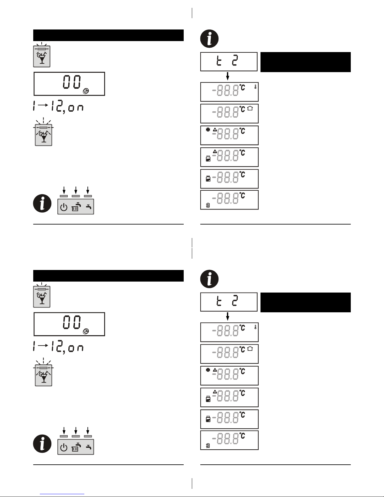
Setting the duration of “party” operation
During active “party” operation press and
hold the key for at least 5 seconds.
With key pressing we can
now set the wanted duration
of “party” operation.
Setting range:
- 1 … 12 hours or
- continuous “party” operation
signalised with “on”
Pressing the “party” key again deactivates the “party”
function. During active “economy” operation it is not possible
to activate the “party” function. “Party” operation usually
ends at time program 1 (CH1), changeover from reduced to
normal operation.
The “party” function can be
selected from all three operating
modes.
5 sec
After the time setting is accepted, the LED above
the key starts blinking.
31 SETTING MANUAL
Wanted and calculated
temperatures
Average (momentarily) outdoor
temperature
Wanted room temperature
Calculated flow temperature of the
first stand pipe (IC)
Calculated flow temperature of the
second stand pipe (DC)
Calculated boiler temperature
Display symbol - - - means that the temperature
isn’t measured and isn’t used by the controller.
Wanted d. h. w. temperature
14 USER MANUAL
Setting the duration of “party” operation
During active “party” operation press and
hold the key for at least 5 seconds.
With key pressing we can
now set the wanted duration
of “party” operation.
Setting range:
- 1 … 12 hours or
- continuous “party” operation
signalised with “on”
Pressing the “party” key again deactivates the “party”
function. During active “economy” operation it is not possible
to activate the “party” function. “Party” operation usually
ends at time program 1 (CH1), changeover from reduced to
normal operation.
The “party” function can be
selected from all three operating
modes.
5 sec
After the time setting is accepted, the LED above
the key starts blinking.
31 SETTING MANUAL
Wanted and calculated
temperatures
Average (momentarily) outdoor
temperature
Wanted room temperature
Calculated flow temperature of the
first stand pipe (IC)
Calculated flow temperature of the
second stand pipe (DC)
Calculated boiler temperature
Display symbol - - - means that the temperature
isn’t measured and isn’t used by the controller.
Wanted d. h. w. temperature

BF2 - storage tank temperature
30 SETTING MANUAL
RLF - return pipe temperature
KF - boiler temperature
RLKF - boiler return pipe
temperature
BF1 - storage tank temperature
KF2 - solid fuel boiler temperature
KTF - solar collectors temperature
RF2 - DD1 separated room sensor
temperature
BDF - estrih temperature
15
USER MANUAL
Pressing the key activates the “economy”
function.
Key “economy”
With key pressing we activate the “economy”
function. Rooms are heated 3 °C bellow the
normal temperature set point.
With this button we can set the wanted
room temperature during “economy”
operation. The wanted room temperature
will be 3 °C bellow the button set point.
With this button we can now again set the
wanted normal room temperature. This
setting is used after “economy” operation
ends.
Setting any wanted “economy” temperature

16 USER MANUAL
Setting the duration of “economy” operation
During active “economy” operation press and
hold the key for at least 5 seconds.
With key pressing we can set
the wanted duration of
“economy” operation.
Pressing the “economy” key again deactivates the “economy”
function. If “party “ function is active, we can’t activate the
“economy” function. “Economy” operation automatically
ends at time program 1 (CH1) changeover.
5 s
The “economy” function can be
selected only from “Room and
d. h. w. heating” operating mode.
Setting range:
- 1 … 12 hours or
- continuous “economy” operation
signalised with “on”
After the time setting is accepted, the LED above
the key starts blinking.
29 SETTING MANUAL
We can change the parameter values for following groups:
“PRO”, “ADT”, “TEL” and “SE1”
We go to the selected parameter, press and
hold the “operation mode” key for
approximately 5 sec. Then we hear a beep
and the display value starts blinking.
Now we use the keys “party” (decrease) and
“economy” (increase) to set the parameter to
the wanted value. To confirm the new value
we must again press the “operation mode”
key for approximately 5 sec.
Measured temperatures
AF - outdoor temperature
RF - room temperature
VF - flow temperature

28 SETTING MANUAL
Factory settings are ass follows:
Group PRO - programming:
- correction of room temperature display ....... 0.0 °C
- beep by timer changeover ............................1 (ON)
- temperature display .....................................2 (room temp.)
Group ADT - heating curve correction
- heating curve slope correction .....................0.0
- parallel shift correction
of the heating curve ..................................... 0.0
Group TEL - remote heating activation by a phone
- selecting the wanted temp. .......... 1 (on the controller)
- heating selection .........................0 (room and d. h. w.
heating)
Group SE1 - service settings 1
- rounding of displayed temp. ................. 0,5 °C
- ''party'' function deactivation ................ 1 (reduced/normal
operation changeover)
- temp. reduction in ''economy'' function .............. -3 °C
- temp. correction of separated sensor .... 0,0 °C
- room sensor selection ........................... 1 (built in sensor)
- outdoor temperature correction ............. 0,0 °C
- time of automatic menu exit ................. 20 sec
- party operation ....................................... 1 (room heating)
17
USER MANUAL
Passive operation of room unit DD1
DD1 is in passive operation if the operating mode selection
switch (on the controller) isn’t in position “remote unit”.
None of DD1 LED’s is active.
The DD1 button and keys have no influence on
controller operation, during DD1 in passive mode.
The keys can only be used for showing the
parameters and temperatures .
The room temperature measurement operates
normally and is used by the controller and
influences its operation.
D1, D2 and CMP12+
ali

18 USER MANUAL
Data display in passive operation
The controllers operating mode selecting switch
is in position “automatic operation”.
Only by D1, D2 and HRD controllers
The controllers operating mode selecting switch
is in position “normal temperature operation”.
normal temp.
(CH1=ON)
reduced temp.
(CH1=OFF)
automatic timer
operation
room
heating
d. h. w. heating
(CH2=ON)
normal temp.
(CH1=ON)
room
heating
d. h. w. heating
(CH2=ON)
27 SETTING MANUAL
Factory settings
To return DD1 to the factory settings we must perform following actions:
o o o o o
30 sec
a) Press and hold key “party” and put DD1
into the socket.
b) If is DD1 already in operation , we must
hold key “economy” for approx 30 sec.
After the display blinks and we here a few
successive beeps, we can release the key.
Local network
Remote phone activation
Heating curve correction
Procedure b) is available only with DD1
software version 2.0 or higher.

26 SETTING MANUAL
Wanted and measured temperatures
Controller settings
Room temperature data
Info
Controller data
Measured temperatures
Programming of basic operation of
room unit DD1
We can select between following groups:
19 USER MANUAL
The controllers operating mode selecting switch
is in position “reduced temperature“ operation
The controllers operating mode selecting switch
is in position “frost protection”
The controllers operating mode selecting switch
is in position “manual operation”
frost
protection
d. h. w. heating
(CH2=ON)
reduced temp.
(CH1=OFF)
room
heating
d. h. w. heating
(CH2=ON)
manual
operation
all pumps and
the boiler are
active

20 INSTALLATION MANUAL
Selecting the installation place
The right installation place is very important. DD1 measures
and uses the room temperature and so we must choose the
right place to measure the actual room temperature.
Such places are on inner
walls, away from direct
sun light and sources of
heat and draught.
INSTALLATION MANUAL
The recommended installation height is
approximately 150 cm above floor.
Display of temperature and other data
To get into group selection we
must simultaneously hold keys
“party” and “economy” for 5 sec.
5 s
To move between groups we use keys “party” and
“economy”. Each group holds its own data. We select a
group with the “operating mode selection key”
25 SETTING MANUAL
Data and settings are divided into 10 groups. The special
group 11 is used for service settings.
move right
between groups
move left
between groups
(PODATKI)
entering into
a group and
moving
between
data
(SKUPINE)

For correct operation we must synchronise DD1 with the connected heating controller. Synchronisation is done after connecting all needed sensors to the controller.
If we don’t perform the synchronisation, an error will be
shown, ERR 02.
Synchronising DD1 with the controller
After the display blinks and we hear a beep
we can release the key.
Synchronisation end is signalised with two
successive beeps.
30 s
a) Press and hold key “party” and put DD1
into the socket.
b) With DD1 already in operation, we must
hold key “party” for approx 30 sec.
SETTING MANUAL
24 SETTING MANUAL
2x
Procedure b) is available only with DD1
software version 2.0 or higher.
After the beep communication between DD1
and controllers starts (approx. 20 sec)
Installing the DD1 room unit
The picture shows how to take
DD1 off from the socket. We use
a screwdriver to push up DD1
(trough the opening on the
bottom part). We pull the upper
part of DD1 up and take it out
from the socket.
After we have selected a suitable
installation place we fix the
socket with two screws to the
wall or sub plaster socket, as
shown on picture.
21 INSTALLATION MANUAL

22 INSTALLATION MANUAL
Connecting DD1 to a heating controller
We use a two wire cable to connect DD1 to a heating
controller (HRD, D1, D2 or CMP12+). See the wiring
diagram bellow. DD1 uses the two wire cable for power
supply and data communication with the controller.
HRD, D1 or D2 controller CMP12+ controller
KONEKTOR C KONEKTOR D
Digital room
unit DD1
Digital room
unit DD1
The maximum allowed cable connection length
between controller and room unit is 50 m.
Connecting Telewarm G1-D
Telewarm G1-D is a remote telephone switch, which enables
us to activate normal temperature operation via a telephone
network. Telewarm G1-D can be connected to the controller
or room unit DD1.
DD1 contacts 3 and 4 are used for connection to G1-D.
23 INSTALLATION MANUAL
home phone outside phone
telecommunications network
230 V a.c.
T connector
connecting box
Telewarm G1-D
digital room
unit DD1
 Loading...