

Page 1
Selmo
I
T
A
f
f
Comforttechnology division
“THESIS DIG
Electronic control for towel radiators
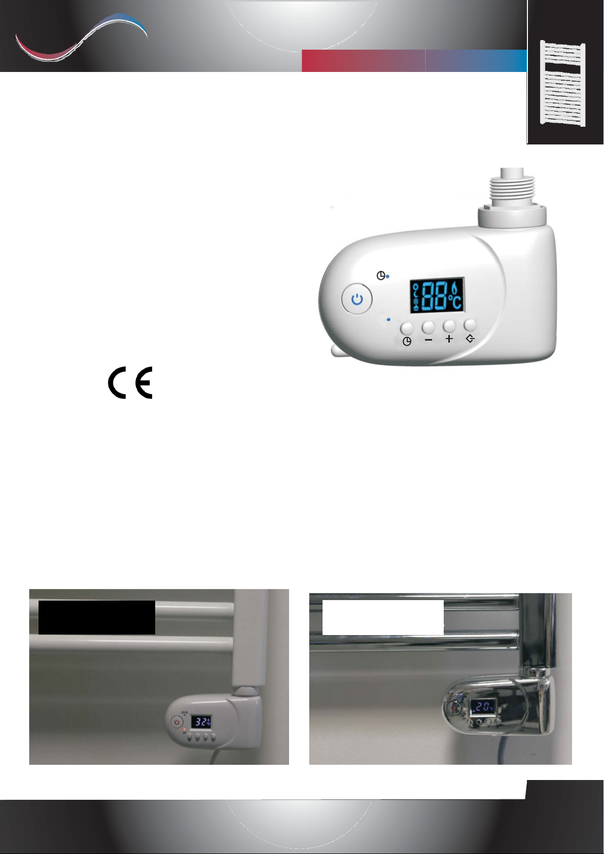
THESIS DIGITAL is an electronic
thermostat for the automatic control o
electric towel radiators. By means of an
external sensor it is capable of keeping the
room temperature at the desired value.
THESIS DIGITAL has a simple yet
modern design, suitable for every type o
furnishing and every model of electric
towel radiator.
THESIS Digital is easy to install and it is
available in several colors.
THESIS Digital is a certified product:
L”
2H/
2H
MAIN OPERATIVE MODES:
Two different modes:
THESIS Digital is compliant with the
following standards:
--EEccoo--ddeessiiggnn DDiirreeccttiivvee ffoorr EEnneerrggyy--uussiinng
Products, 2005/32/EC (<0,5W).
- EN 60335-1:2012 - EN 60335-2-30:2011
- EN 60335-2-43:2008
- EN 55014-1:2008 - EN 55014-2:1998
- EN 61000-3-2:2004 - EN 61000-3-3:1995
- EN 50366:2003
g
White
• Thermostat mode:the room temperature is
detected by the external sensor.
The user can set the device’s behavior by
choosing one of the following four subfunctions: "Comfort", "Night", "Antifreeze",
"Fil-Pilote".
• Timer mode: the internal electric resistance is
activated for a period of 2 hours. This operation
can be repeated every day (“2h-repeated” sub-
function) or on user request (“Timer-2h” sub-
function)
Chrome
Rev. 06 - October 2015
Selmo Electronic
Viia Pacinotti, 24 - 35030 Rubano (PD) Italy- Tel +39.049.8976761, Fax +39.049.8976085 - www.selmo.it
EN
Page 2
Selmo
I
T
A
T
E
E
Comforttechnology division
Electronic control for towel radiators
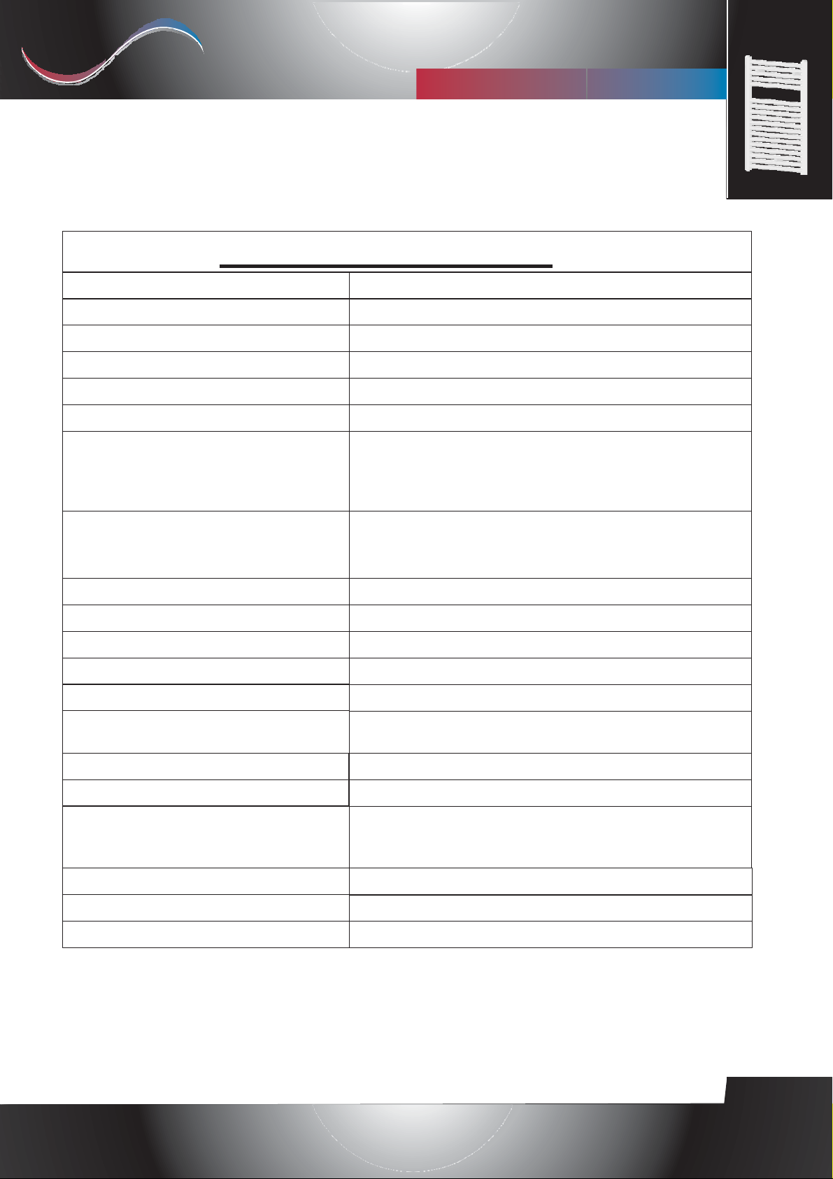
Product
Applications
Versions
IP level
Fil-Pilote
emperature setting
Indication lights
Operational modes
“THESIS DIG
caratteristiche tecniche
Digital electronic thermostat for towel radiators
Towel radiators
Class I, Class II
IP44
Available only for Class II models
Digital ([ + ] and [ - ] buttons)
- Backlit On/Off button.
- Led indicating the selected functional mode.
- Led display.
-Comfort, Night, Antifreeze, Fil-Pilote, Timer-2h,
2h-repeated.
L”
Selectable temperature range
Operating temperature range
Maximal power
Supply voltage
Size
Connection to the heating element
Room temperature sensor
Warranty
Compliant standards
Certification mark
nvironmental directives
lectromagnetic compatibility
10°C ÷ 32°C
-10°C ÷ +40°C
2000W
230VAC 50Hz
113 x 73 x 40mm
Faston connector 6.3x0.8mm: Neutral, Live and Earth
(only for Class I device)
10K at 25°C
2 years
EN 60335-2-43, EN 55014-1, EN 61000-3-2,
EN 61000-3-3, EN 55014-2, EN 50366
EN 60335-1, EN 60335-2-30,
CE
WEEE, RoHS
89/336/EEC
Rev. 06 - October 2015
Selmo Electronic
Viia Pacinotti, 24 - 35030 Rubano (PD) Italy- Tel +39.049.8976761, Fax +39.049.8976085 - www.selmo.it
EN
Page 3

Selmo
I
T
A
Comforttechnology division
“THESIS DIG
Electronic control for towel radiators
WARNING
RISK OF ELECTRIC SHOCK!
Disconnect power supply before proceeding with installation.
L”
Preserve the present instruction sheet and read carefully before using the device.
• The present device has been designed for exclusive use on a towel radiator.
• The thermostat is designed for heating the liquid contained inside a towel radiator in
combination with a heating element. Any other use is forbidden.
• Before using, carefully ensure that the line voltage is the same as that specified for the device
(see technical specifications).
• Only use heating elements compatible with the type of towel radiator being used.
• Disconnect power supply before cleaning or performing maintenance of the product.
• In case of damage of the power supply cable shut down the device and do not tamper with it.
The damaged power supply cables can be replaced exclusively by the manufacturer or by an
authorized service center. Failure to comply with the above rules could lead to compromised
system safety and void the warranty.
• Store and transport the heating element exclusively in the protecting packaging.
• Replacement of the heating element can be done exclusively by the product manufacturer.
CONNECTIONS TO ELECTRIC MAINS
The available versions are the following:
• 1 Schuko plug (Class I or Class II) for direct connection.
• 3-wires for Class I models: Live (brown); Neutral (blue); Earth (green-yellow).
• 2-wires for Class II models: Live (brown), Neutral (blue).
• 3-wires for Class II models with "Fil-Pilote": Live (brown), Neutral (grey), "Fil-Pilote" (black).
Rev. 06 - October 2015
Selmo Electronic
Viia Pacinotti, 24 - 35030 Rubano (PD) Italy- Tel +39.049.8976761, Fax +39.049.8976085 - www.selmo.it
EN
Page 4
Selmo
I
T
A
d
Comforttechnology division
“THESIS DIG
L”
Electronic control for towel radiators
Installation Guide
For installer only
WARNING:
Disconnect the power supp ly bef ore procee di ng wi th i nst all ati on.
The installation has to be performed by authorized personnel only.
• Connection of the device to the electric resistance must be performed by authorized
personnel only.
• Make sure that the power of the electric resistance does not exceed the maximum power
of the towel radiator.
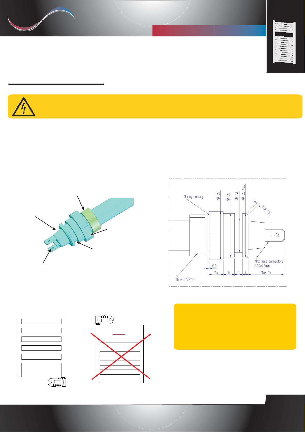
Example of heating element (Class II)
Threa
Insulation
Fastening area
of the thermostat
2 Faston connectors 6.3x0.8mm
YES
Fastening area
NO
IMPORTANT: Be aware of the
maximal length of the 19mm connector
(see picture above). Longer connectors
could damage the device.
Rev. 06 - October 2015
Selmo Electronic
Viia Pacinotti, 24 - 35030 Rubano (PD) Italy- Tel +39.049.8976761, Fax +39.049.8976085 - www.selmo.it
EN
Page 5

Selmo
I
T
A
c
Comforttechnology division
“THESIS DIG
L”
Electronic control for towel radiators
• Disconnect power supply before installation.
• Connection of the device to the electric resistance must be performed by authorized personnel only.
• Make sure that the power of the electric resistance does not exceed the maximum power allowed by the electroni
control device.
1. Make sure that the towel radiator does not have leakage or air lock.
2. The device shall not be positioned directly in front of an electric plug.
3. Prevent water jets from hitting the equipment.
4. Connect the temperature controller only to a suitable heating element.
5. Ensure that the mains voltage is the same as indicated in the technical specifications.
6. Make sure that the type of electric resistance is compatible with the model of towel radiator being used
(check the product specifications provided by the manufacturer). The usage of a heating element with
higher power:
- Does not increase the actual power of the towel radiator;
- Might shorten life of the heating element;
- Could damage the equipment.
7. Make sure that the power of the electric resistance does not exceed the maximum power of the towel
radiator (check the label on the heating element).
8. When installed in a room with bathtub or shower, respect the “Protection Zones” according to IP44
insulation class (in UK according to IEE cabling directives). Furthermore, make sure to respect all local
safety directives.
9. The device has to be protected by a 30mA circuit breaker (RCD).
10. Power the device with the recommended voltage (see technical specifications).
11. If a device is directly connected to a fixed electric installation, install an isolating switch compliant with
local directives for power supply disconnection.
12. Place the "O-Ring" before the fastening area.
13. After ensuring that the "O-Ring" is correctly positioned, screw the electric resistance in the relevant
threaded hole of the towel radiator, properly secure it and insert the cover ring.
14. Extract the connecting cables from the device. The four poles connector and the ground connector (only
Class I).
15. Connect the 2 Faston connectors to the corresponding connectors of the heating element.
16. Connect the female Faston connector to Earth (only Class I).
17. Insert the lower part of the heating element into the ready connected thermostat.
18. Align the device to the towel radiator. Warning! Do not rotate the device more than 30 degrees on
both directions.
19. Push the device against the base of the heating element to compress the “O-Ring”, properly fix the
related fastener so that the device remains well secured and does not rotate around the heating element.
20. Connect the power supply cable.
Rev. 06 - October 2015
Selmo Electronic
Viia Pacinotti, 24 - 35030 Rubano (PD) Italy- Tel +39.049.8976761, Fax +39.049.8976085 - www.selmo.it
EN
Page 6
Selmo
I
T
A
Comforttechnology division
“THESIS DIG
Electronic control for towel radiators
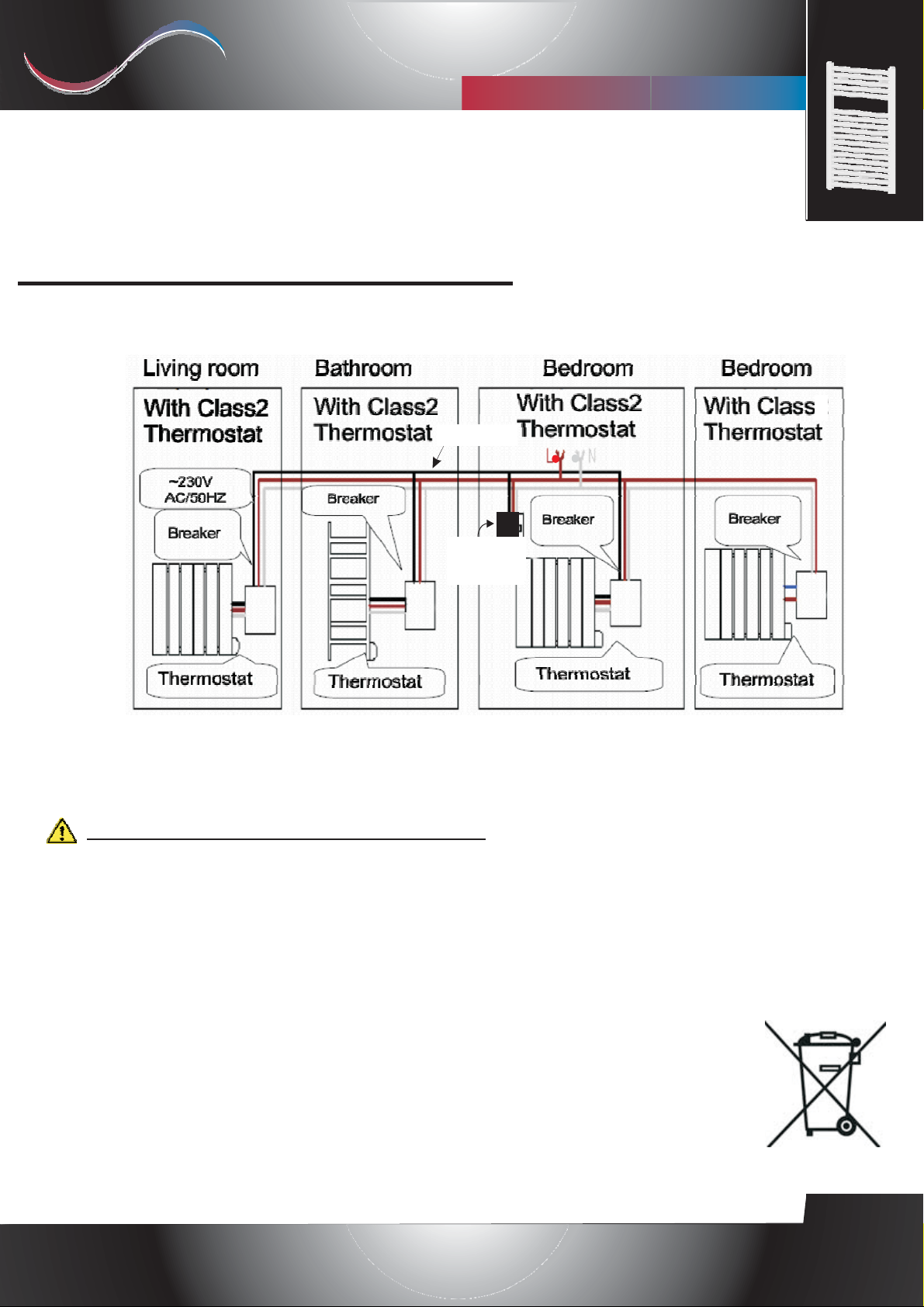
Connection to Fil-Pilote system
(Only for product versions equipped with "Fil-Pilote")
Example
"Fil-Pilote"
"Fil-Pilote"
Station
L”
1
1
1. A Thesis Digital device supporting "Fil-Pilote" functionality(classeII) can be remotely
controlled by a control unit supporting the "Fil-Pilote" system. The brown wire is the Live
wire (L), the gray wire is the Neutral wire (N) and the black wire is used for receiving the
Fil-Pilote signal.
Do not connect the black wire to the Earth.
2. A Thesis Digital device without "Fil-Pilote" functionality (Class I) cannot be remotely
controlled. The brown wire is the Live wire (L), the blue wire is the Neutral wire (N)
and the yellow/green wire has to be connected to Earth.
DISPOSAL
This product may not be treated as ordinary household waste. It has to be disposed in
proper waste collection sites. In case of replacement it shall be returned to the
distributor.
Such an end-of-life treatment of the product will preserve the environment and will reduce
consumption of natural resources.
This symbol applied to the present product indicates the obligation to bring it to a
proper waste collection site, in order to let it be disposed according to 2002/96 / CE
(RAEE - WEEE) directives.
Rev. 06 - October 2015
Selmo Electronic
Viia Pacinotti, 24 - 35030 Rubano (PD) Italy- Tel +39.049.8976761, Fax +39.049.8976085 - www.selmo.it
EN
Page 7
Selmo
I
T
A
(2)
b
g
Comforttechnology division
Electronic control for towel radiators
User guide
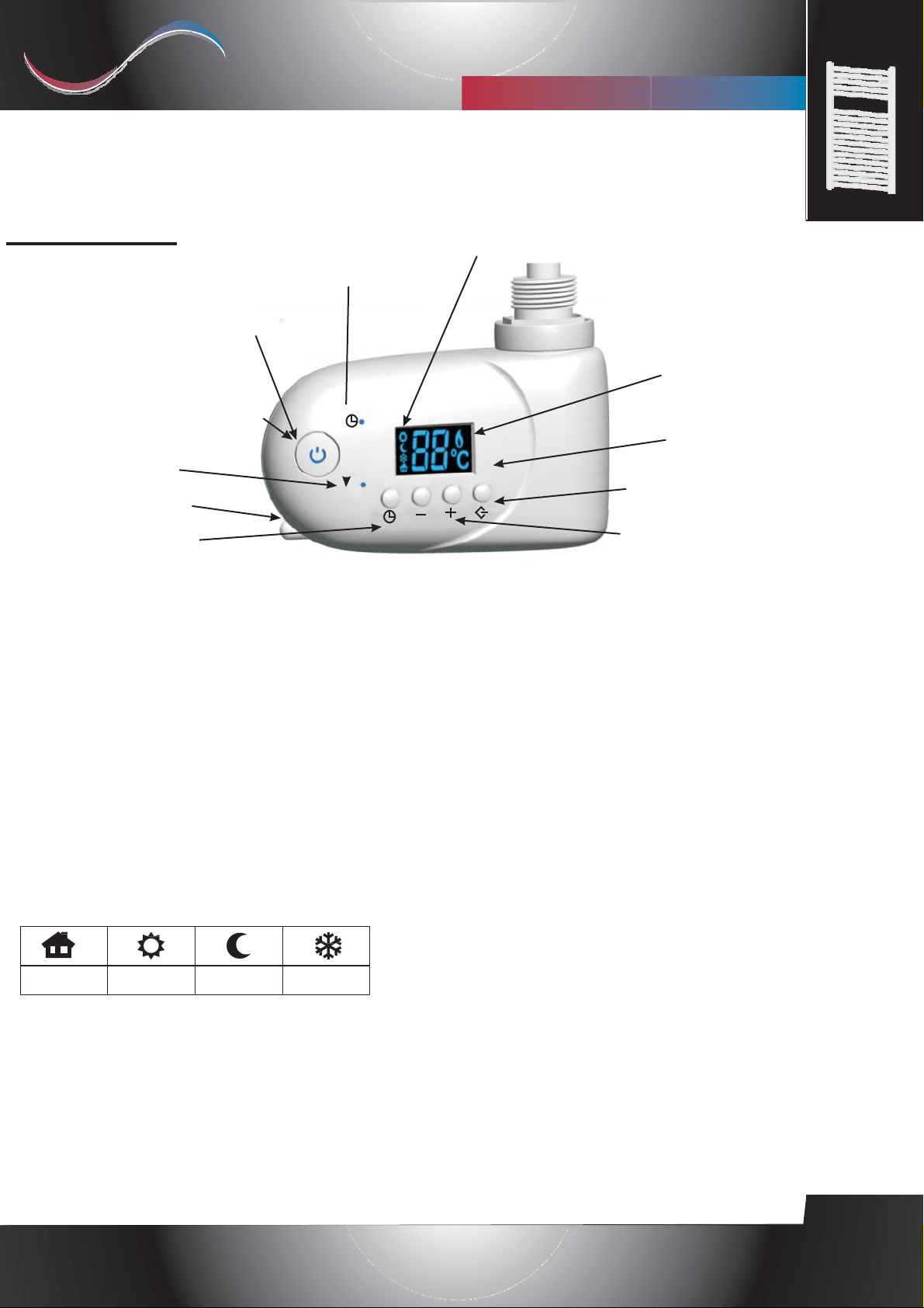
(1) [On/Standby] backlit
button
(11) Red / blue LED on
[On/Standby] button
(3) "Timer-2h" LED indication
(4) External sensor
(5) [Select] button
“THESIS DIG
"2h-repeated" LED indication
2H/
2H
L”
(10) Active sub-function indication
(9) Powered heating
element indication
(8) LED Display
(6) [Mode] button
(7) [+] and [-] buttons
OPERATION
The [On/Stand-by] button (1) is used to turn on the device or to enter the "Standby" mode. A red light (11) indicates
that the device is turned on; a blue light (11) indicates that the device is in "Standby" mode.
NOTE: When the device goes into “Stand-by” mode it beeps twice for 0.5s.
When the device is activated it beeps once for 1s
THERMOSTAT MODE
In this operative mode the user can set the desired room temperature through the [+] and [-] buttons (7) in a range
etween 10°C and 32°C. The external sensor (4) is used in this mode for detecting the room temperature and allows the
automatic temperature control.
If the selected temperature is higher than the room temperature, the active heating indication icon (9) is shown on the
display and the heating element is being powered until the room temperature reaches the selected temperature value.
When the room temperature reaches the desired value, the heating element is switched off and the active heating
indication icon (9) is turned off on the display.
SUB-FUNCTIONS
Fil-Pilote
The 4 sub-functions above can be selected through the [Mode] button(6).
"Comfort" - Icon "sun" (10); it is the default function (already described above).
ht" - Icon “moon” (10); it is similar to the "Comfort" function, but the temperature range is between +9°C
"Ni
and 31°C.
NOTE: The “Night” temperature is always be low the “Comfort” temperature. The “Comfort” temperature can thus be
set in a range between the currently set “Night” temperature + 1°C and 32°C, and analogously the “Night” temperature
can be set between 9°C and the currently set "Comfort" temperature.
"Antifreeze" - Icon “snow flake” (10); the temperature remains fixed to 7°C.
Comfort
Night
Antifreeze
Rev. 06 - October 2015
Selmo Electronic
Viia Pacinotti, 24 - 35030 Rubano (PD) Italy- Tel +39.049.8976761, Fax +39.049.8976085 - www.selmo.it
EN
Page 8

Selmo
I
T
A
(5) (2)
Comforttechnology division
“THESIS DIG
L”
Electronic control for towel radiators
"Fil-Pilote" – Icon “Home” (10); to activate this sub-function press the [Mode] button (6) until the "Fil-Pilote”
icon is shown on the display.
(This functionality is only available for products equipped with "Fil-Pilote" connectivity)
This sub-function allows managing the device by a central control system that sets the operating mode for each of
the connected devices.
The device even recognizes the most advanced 6-commands based "Fil-Pilote" system that allows the execution of
the following functions:
1. Standby: power off the heating element, the device remains active.
2. Comfort: maintains the "Comfort" temperature set by the user.
3. ECO: maintains the room temperature 3,5°C below the "Comfort" temperature.
4. Anti-freeze: maintains the room temperature at 7°C.
5. Eco-1: maintains the room temperature 1°C below the "Comfort" temperature.
6. Eco-2: maintains the room temperature 2°C below the "Comfort" temperature
TIMER MODE
This operating mode can be accessed through the [Select] button (5). By repeatedly pressing this button it is
possible to select between the following options:
1.
Enter the "Timer-2h" sub-function.
2.
Enter the "2h-repeated" sub-function.
3.
Exit any of the previous sub-functions.
TIMER-2H: "Timer-2h" LED (3) is turned on.
The device powers the heating element for 2 hours independently of the room temperature. At the end of the 2
hours period the device returns to the previous operating mode and the “Timer-2h” LED (3) is turned off. Press
the [Select] button (5) twice to deactivate the "Timer-2h" sub-function. Both LEDs (3) and (2) should appear
turned off.
2H-REPEATED: "2h-repeated" LED (2) and "Timer-2h" LED (3) are turned on.
The device powers the heating element for 2 hours independently of the room temperature. At the end of the 2
hours period the device returns to the previous operating mode and the “Timer-2h” LED (3) is turned off.
The procedure is then repeated every day endlessly. Press the [Select] button (5) to deactivate this sub-function.
Both LEDs (3) and (2) should appear turned off.
NOTE. In “Timer-2h” and “2h-repeated” modes, the maximal temperature is automatically limited to 32°C.
STANDBY:
In "Standby" mode the heating element is powered off.
KEY LOCK
Press together [Select] (5) and [Mode] (6) buttons for 5 seconds to lock all the buttons (except the
[On/Stand-by] button). When key lock is activated, a “LO” indication is displayed on the screen.
To unlock the buttons, repeat the same procedure.
The manufacturer reserves the right to make any changes to the product described in this
manual, at any time, and without prior warning.
Rev. 06 - October 2015
Selmo Electronic
Viia Pacinotti, 24 - 35030 Rubano (PD) Italy- Tel +39.049.8976761, Fax +39.049.8976085 - www.selmo.it
EN
 Loading...