

Page 1

QUICK START GUIDE
IMPORTANT : Read manual thoroughly for full safety and product information.
.
Package contents
1 x Main unit
1 x Controller
1 x Router
1 x PoE adaptor
2 x LAN cable
1 x Controller cable
1 x Power input cable
1 x Cable holder
1 x Cable gland
1 x Screw set
1 x User manual
Connection diagram
CONTROLLER
www.selfsat.com
MAIN UNIT
Power input cable
Controller cable
WLAN router
LAN WAN Power
LAN cable
Page 2

1. Product specifications
Parts of Main unit
Antenna
Mounting plate
Parts of Controller
• Front
to Controller ("ANT" port)
to router
Power S/W
• Back
Satellite LEDs
USB port
TRACKING LED
LOCK LED
Arrow buttons
OnLED Indicator
IDU cable to Main unit Power port
ENGLISH - 2
SET button
BlinkingO
Page 3

2. Functional description
A. In-Motion mode (only)
a.
When the all cable connections are completed, turn on the power switch
b.
ASTRA2 and HOTBIRD LEDs light on while booting the system (15~30 seconds)
c.
Default (ASTRA2) or the last status satellite is automatically selected
d.
Tracking LED light on since the unit searches the satellite
e.
When Lock LED becomes solid this means the satellite is found
f.
If the other satellite is desired, move to the correct satellite and press SET to
conrm the new satellite
For example :
B. Factory reset
a.
Press and hold SET button for more than 5 seconds till TRACKING & LOCK
LEDs blink
b.
Factory reset takes less than 3 seconds and reboot the system
c.
When factory reset is completed, default satellite is selected then the unit
automatically starts searching
ENGLISH - 3
Page 4
3. Extra functions
A. Software upgrade - Controller
a.
Transfer “FWUPDATE.BIN” le to a USB stick. Do not place inside a folder
b.
Ensure that the unit is turned o and plug the USB into USB port on the
back of controller
c.
Press and hold SET button and turn on the Power switch
d.
MODE LED is on while checking upgrade le
e.
Software upgrade takes about 10 seconds
(Each LED lights in sequence, all LEDs light on and then o)
f.
Once upgrade is completed, unit reboot(reset) the system
g.
If controller does not recognise USB, MODE /Tracking /Lock LEDs blink 6
times and restart
h.
If upgrade is failed, all satellite LEDs blink till the unit is turned o
B. Software upgrade – Main board
a.
Transfer “FWUPDATE.BIN” le to a USB stick. Do not place inside a folder
b.
Ensure that the unit is turned on and plug the USB into USB port of main
board (inside antenna)
c.
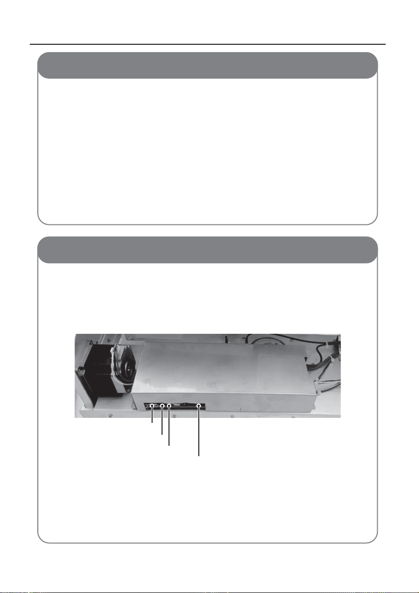
Press and hold UPDATE button and then press RESET button
(There may be noise when pressing RESET button. It is not faulty.)
USB port
Update button
Red & Green LED
Reset button
d.
Red and green LEDs are on while checking upgrade le
e.
Software upgrade takes about 10 seconds
f.
Once upgrade is completed, red LED is o and only green LED remains on
g.
If main board does not recognise USB, red and green LED blink 5 times and
restart
h.
If upgrade is failed, red LED blinks 5 times and restart
ENGLISH - 4
Page 5
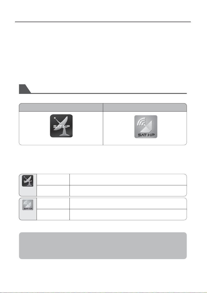
4. Live Satellite Broadcasting with SELFSAT WAVE
SELFSAT WAVE client is either a software App or a STB-type device specialized for the IP
stream from SAT>IP.
SELFSAT WAVE is equipped of two SAT>IP routers, users are able to select one to be
connected.
Each router is capable to stream up to 16 users. Users should be grouped in two and guided
a router name to be connected.
For tablets or smart phones, download any of the SAT>IP Apps on the Apple APP Store or
Google Play.
How to download/use the App for iOS/Android Smartphones and Tablets
Download a SAT>IP App from Apple App Store or Google Play.1.
ELGATO SAT>IP (0.99 EUR)
**Recommended for more stable use with SAT>IP
Install the App on your iOS or Android device.
2.
Wi-Fi Setting
3.
Open the setting on your mobile device & Go to Wi-Fi setting to select the network.
⇒ For SELFSAT WAVE, use SSID “Idoit_wi_XX_5G_1” and password “idoit1234”.
Start the App.4.
Setting → Scan Channels → Select Country → Select Satellite
→ Channel Auto Scan
Live TV → Select Satellite → Select the channel → Watch TV
Scan channels → New channel scan → Select satellite → OK
→ Save → Watch TV
Select the channel and watch TV
Elgato
Sat>IP
tivizen
SAT>IP
Satellite Setting
Watch TV
Satellite Setting
Watch TV
tivizen SAT>IP (Free)
Note) Channel scanning time can be dierent depending on your target satellite and
the number of channels.
Once you nished channel scanning for the rst time, you do not need to do it again.
When running an APP, there is two available SAT>IP server, please select.
ENGLISH - 5
Page 6
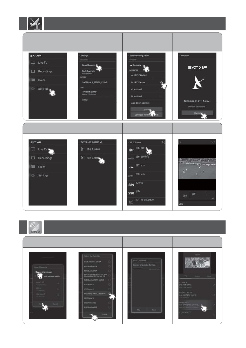
How to use ELGATO Sat>IP App
Setting Scan Channels Auto Scan
Live TV Select the channel Watch TV
Select Satellite
Select Country
Select Satellite
Scan
How to use tivizen SAT>IP App
New channel scan Select Satellite Channel Scanning Watch TV
ENGLISH - 6
Page 7
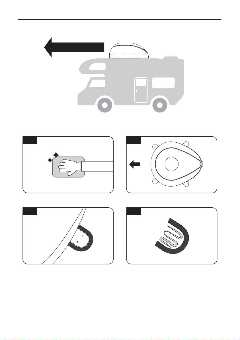
5. Installation
Driving direction
1
Clean the surface with cleaner
3
Attach friction tape outside of the mounting
plate, to be 4mm away from the plate edge
2
FRONT
Locate the antenna in the center of car roof
4
Put aside the antenna to apply silicone inside
the guided tape line
ENGLISH - 7
Page 8
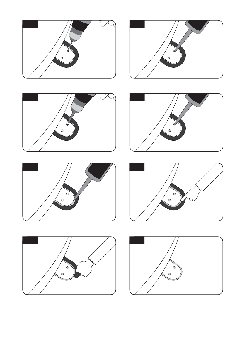
5
6
Put back the mounting plate on the silicone
applied and make 2holes (2mm) with power drill
7
Assemble mounting plate using 2 M4x20 screws
9
Apply silicone around the mounting plate
11
Apply silicone on the holes
8
Re-apply silicone to cover tightened screws
10
Tidy the area silicone applied
12
Remove the friction tape and get dry
The image you will see. Place main unit on the
top of xed plate
ENGLISH - 8
Page 9
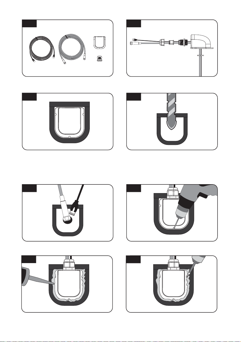
1413
Equipment to initiate cable holder installation
15
Arrange cable holder in front of (30cm apart
from) antenna center by facing open side of
cable holder toward projected part of the
mounting plate. Then attach friction tape
outside of cable holder
17
Insert LAN and controller cable through the
hole
19
Put the cable inside the cable holder as above
picture
16
Make 15mm drill hole in the center of the tape
marking
18
Place cable holder in the tape marked and make
3 of 2mm drill holes
20
Apply silicone around the cable holder
Fix cable holder on the car roof with 3 of M4x20
screws
ENGLISH - 9
Page 10
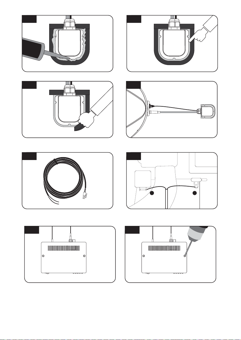
21
+
-
22
Apply silicone around and on the top of screws
23
Remove friction tape
25
Get power input cable for battery connection
Tidy silicon
24
Connect the cable to the controller and router
26
+
Match the power cables polarities to the battery
polarities, red to red / black to black
2827
Plug the other end of power input cable to the
controller
ENGLISH - 10
Place the controller at where user wants
 Loading...