

Page 1
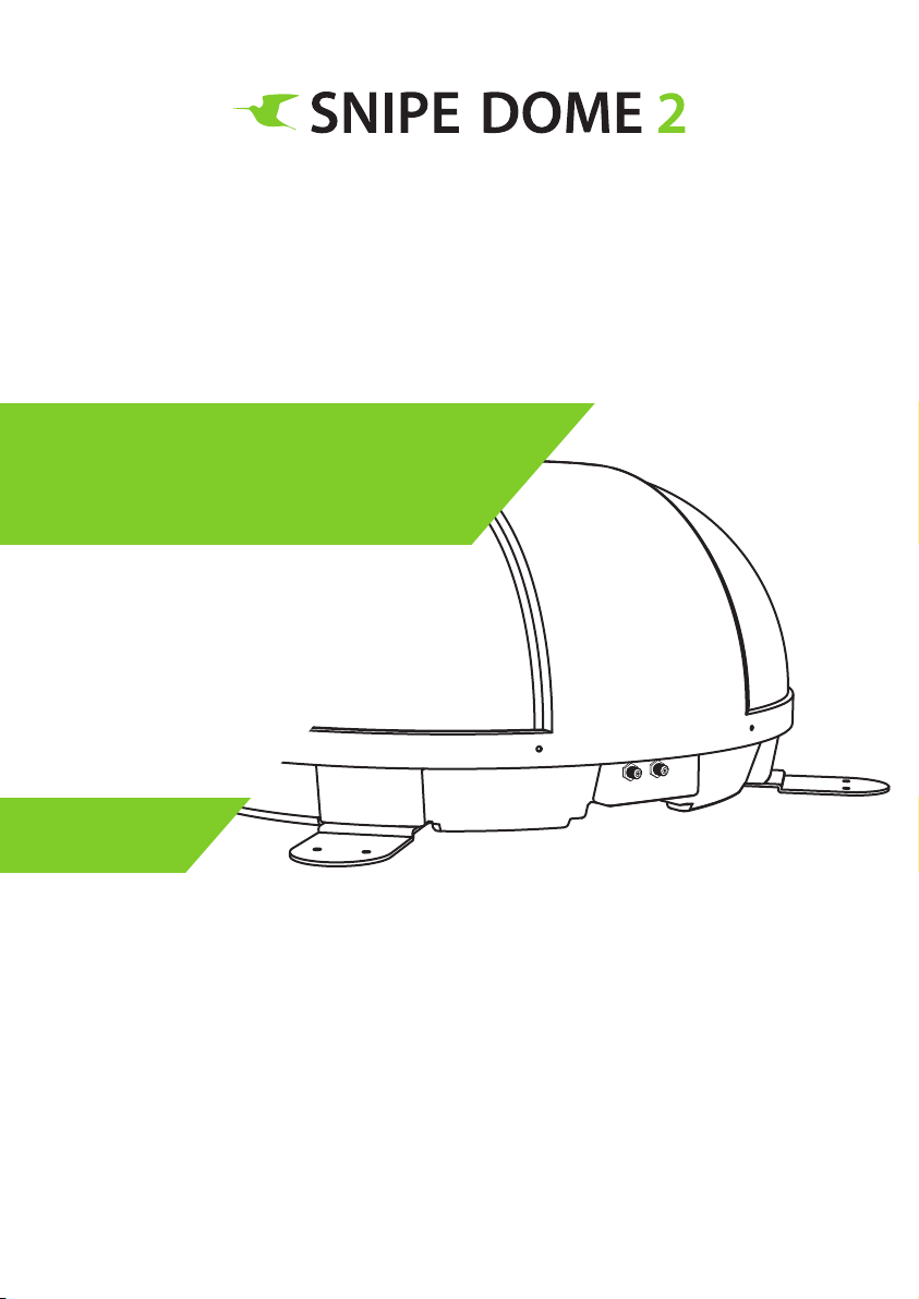
Stationary Automatic
Camping Satellite Antenna
User’s manual • Bedienungsanleitung • Manuel utilisateur
ver. 1.0
www.selfsat.com
Page 2

Contents
1. General Information
1-1. Introduction
1-2. Proper use and operation
1-3. Safety notes
2. Contents
2-1. Accessory included
2-2. Name of parts
3. Operating Instruction
3-1. Connection diagram
3-2. Functional description
3-3. Quick reference
.............................................................................................
.............................................................................................
.......................................................................................
...........................................................................................
....................................................................................
..................................................................................
.........................................................................................
...............................................................................
2
3
3
4
5
6
7
11
4. Software Upgrade
5. Troubleshooting
................................................................................
...............................................................................
6. Specifications
6-1. Dimension
6-2. Specifications
...............................................................................................
............................................................................................
7. Caravan/Motorhome Installation
7-1. Precaution before installation
7-2. Required space for SNIPE DOME 2
7-3. Equipment for installation
7-4. Instruction for installation
..........................................................................
..............................................................................
..............................................................................
..............................................................................
11
12
13
14
15
16
17
17
Page 3
1. General Information
1-1. Introduction
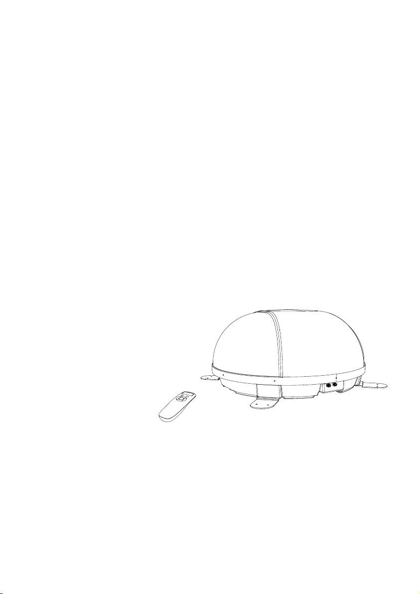
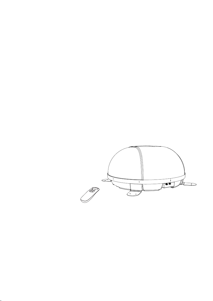
These instructions describe the functions and operation of the SNIPE DOME 2 satellite
system. Correct and safe operation of the system can only be ensured by following these
instructions.
Your SNIPE DOME 2 is an intelligent satellite TV reception antenna system which can align
itself towards a preset satellite automatically as long as the system is located within the
footprint of this satellite.
For general operation, please ensure that the system always has a clear view to the sky. If the
satellite‘s signal beam is interrupted by obstacles such as mountains, buildings or trees, the
unit will not function and no TV signal will be received
The first few pages of these instructions contain information about using the general
functions of your SNIPE DOME 2, followed by an explanation of all the adjustment options.
The last pages of the instructions cover various technical aspects of the SNIPE DOME 2.
ENGLISH - 2
Page 4

1-2. Proper use and operation
This product has been designed for fixed installation on vehicles with maximum speeds of
130 km/h. The unit is programmed to automatically aims at geostationary television
satellites.
The power is supplied by a standard vehicle electrical system with a rated voltage of 12 or 24
Volts DC. For installations on the vehicle, use power input cable (cigarette lighter cable) to
supply power. For portable use, optional power adaptor produced by SNIPE series manufacturer must be used.
Use of the equipment for any other purpose to the one specified is not permitted.
Please also note the following instructions from the manufacturer :
•
It is not possible to add or remove components on this product.
•
The use of other components other than those originally supplied is not permitted.
•
To complete installation, installer must strictly follow instruction in the supplied user manual.
Failure to follow the user manual may cause damage to the unit or user's vehicle.
•
The product does not require any regular maintenance; all service must be carried out at
approved service centers.
All relevant guidelines of the automotive industry must be observed and complied with.
•
The equipment must only be installed on solid vehicle roofs.
•
Avoid cleaning user's vehicle with the mounted satellite system in a drive-through car wash or
•
a car wash with a high-pressure cleaner.
1-3. Safety notes
Please carefully read and follow the operating instructions in this manual and use the
SNIPE DOME 2 for its intended purpose.
Upon installation of SNIPE DOME 2, please ensure the installation is done with supplied
cables and ensure the cables are not modified in any way.
As the user of this equipment, be responsible for ensuring compliance with the relevant
laws and regulations.
The manufacturer does not take liability for direct or indirect consequential damage of
the system, motor vehicles or other equipment by reason of unsuitable battery usage or
erroneous installation or wrong wire connection.
ENGLISH - 3
Page 5
2. Contents
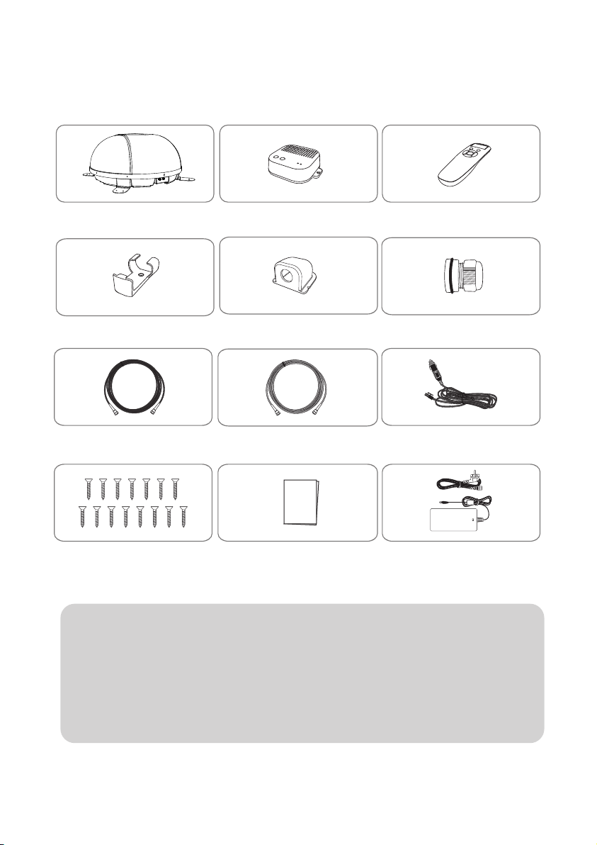
2-1. Accessory included
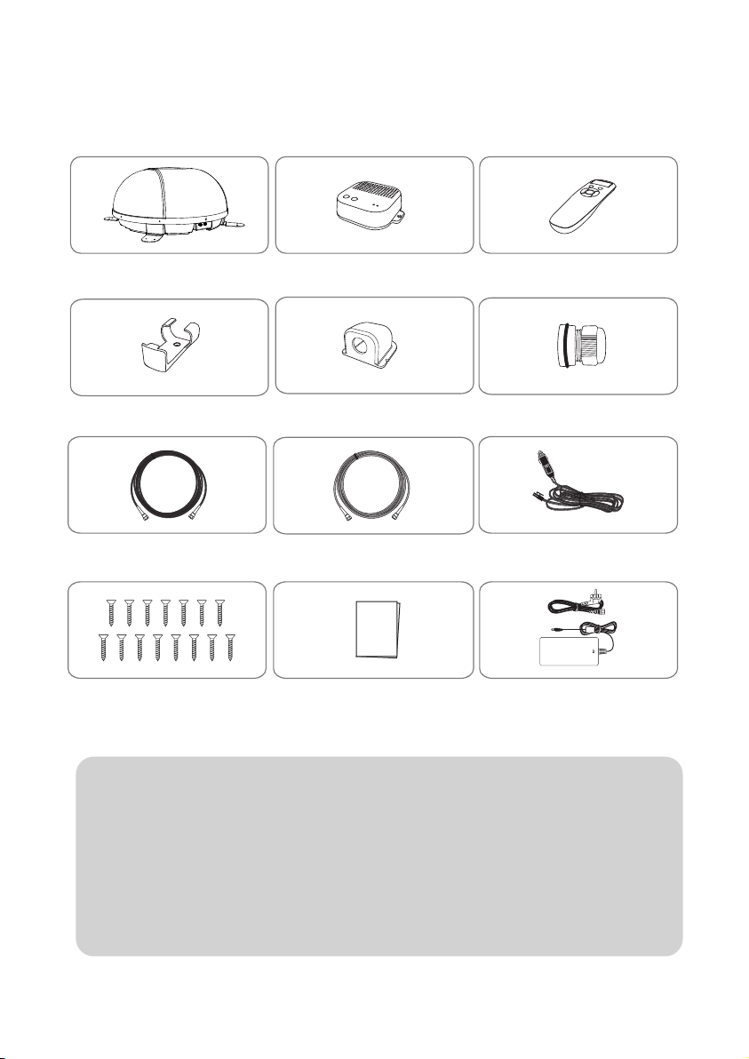
Main unit PI box
Cable holder Remote control Bracket
PI cable - 1.5m
M4 ×20(15)
Actual components may differ from the above images.
※
The unit enables to have power from car battery. To make power input cable for
※
Signal cable -10m
(x2 for twin outputs)
User manual Power adaptor
Remote control
Cable gland
Cigarette lighter adaptor
(Optional)
direct connection, cut off cigarette lighter adaptor and peel off to take copper
cables out.
Only power adaptor produced by SNIPE series manufacturer is guaranteed and
※
has be used.
Power adaptor has to be purchased separate. Please ask to local dealer/shop for
※
more information.
ENGLISH - 4
Page 6
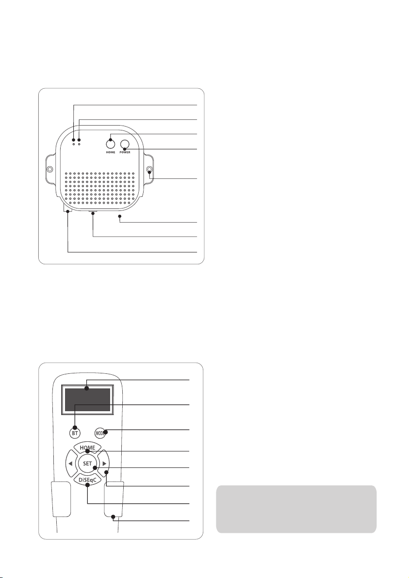
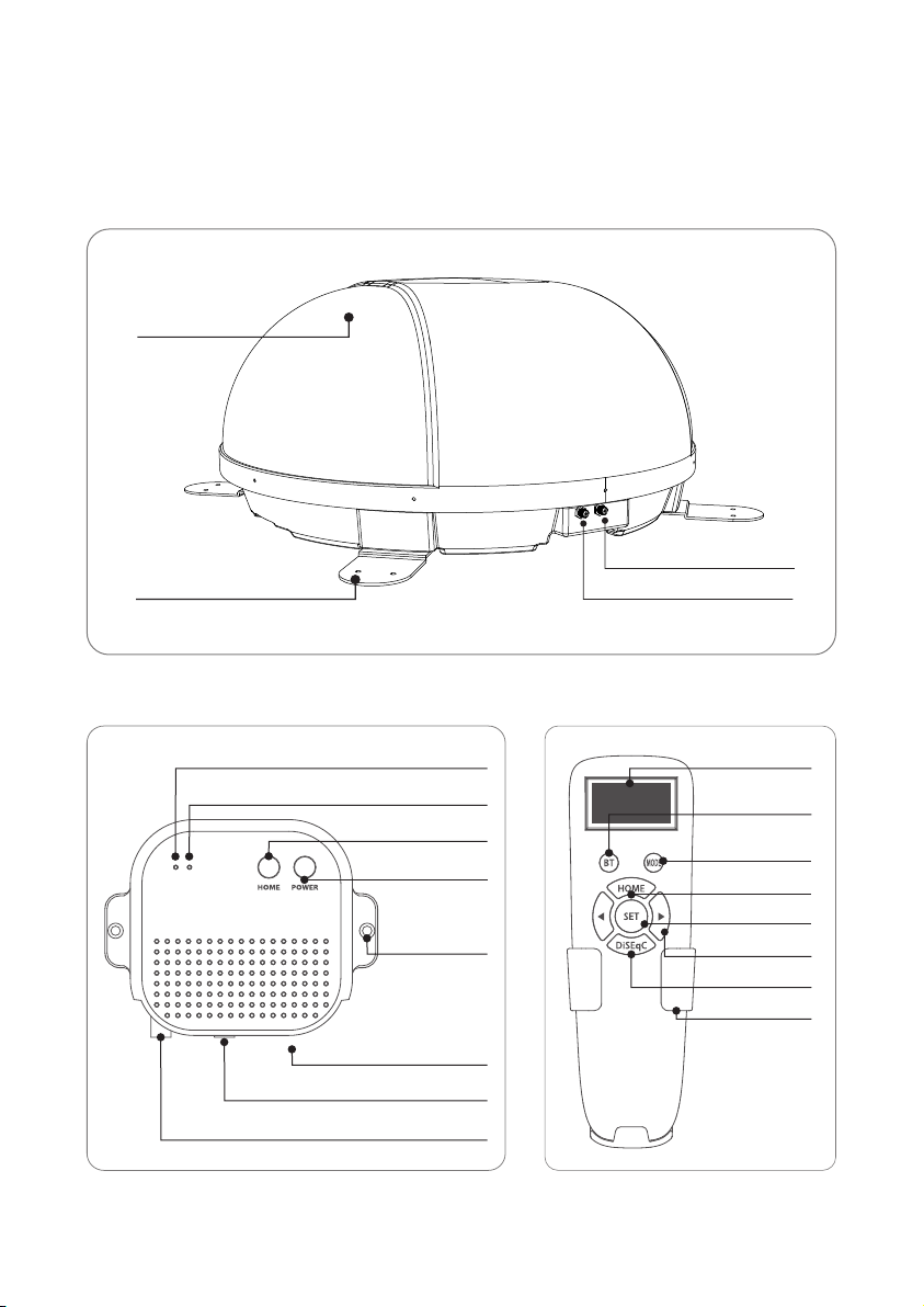
2-2. Name of parts
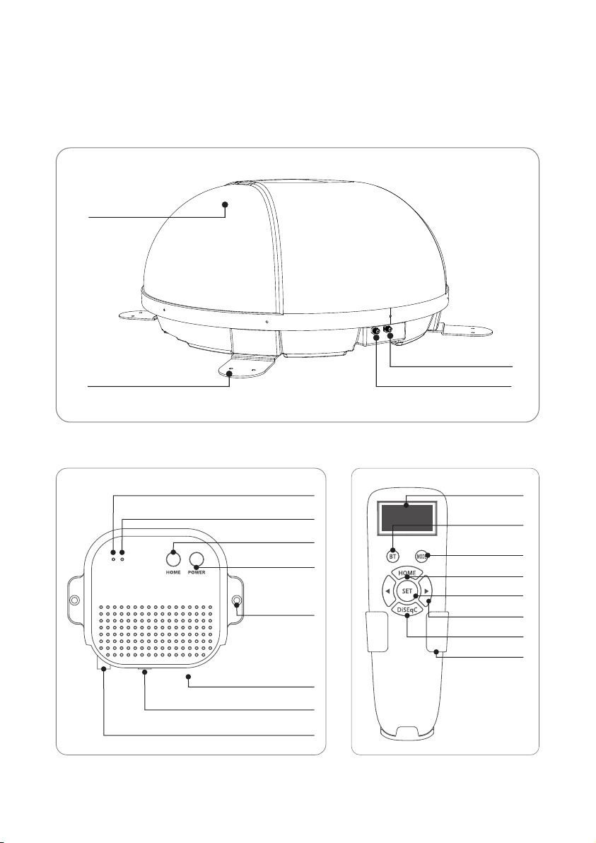
Main unit
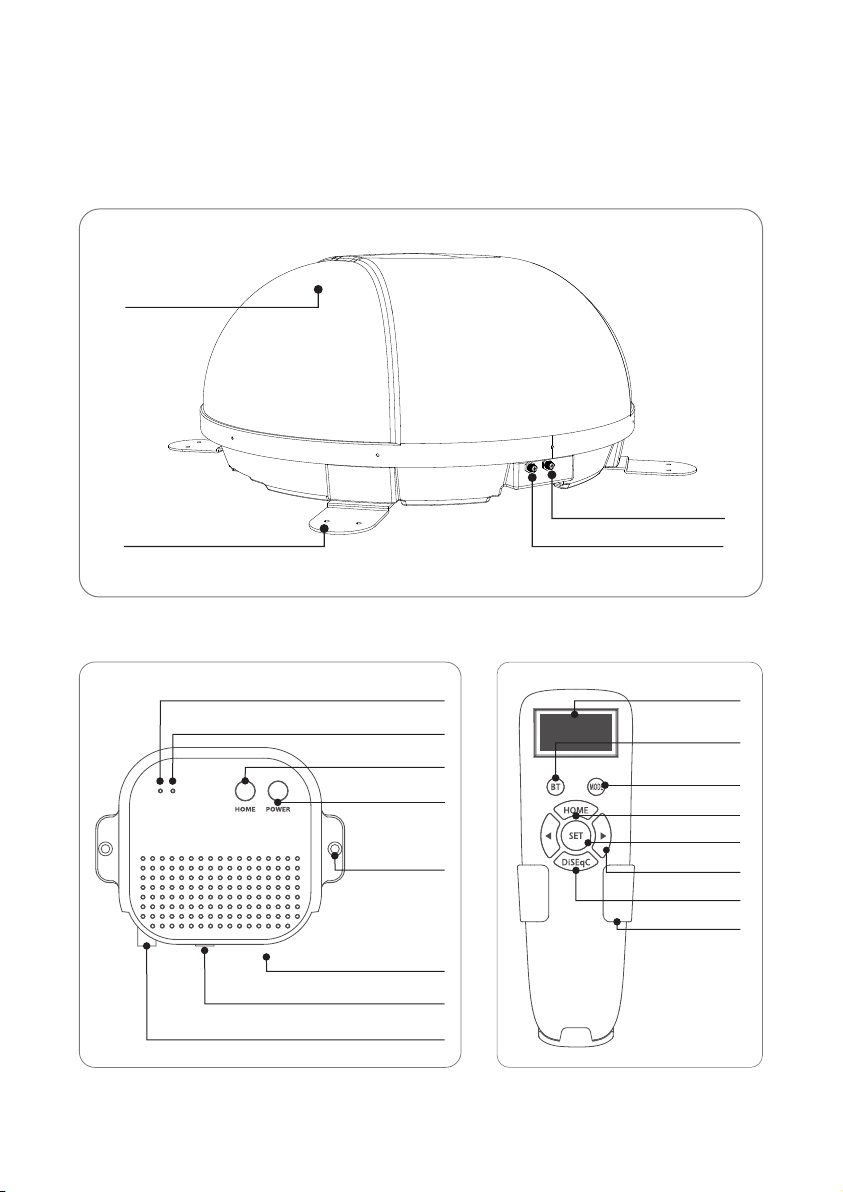
Antenna
Mounting plate
PI box Remote control
to Receiver (optional)
to PI (ANT Port)
STB LED
POWER LED
HOME button
POWER button
Fixed hole
Power
to STB
to unit
ENGLISH - 5
Display window
BT button
Pairing antenna
with remote control
Mode button
HOME button
SET button
Arrow button
DiSEqC button
Bracket
Page 7
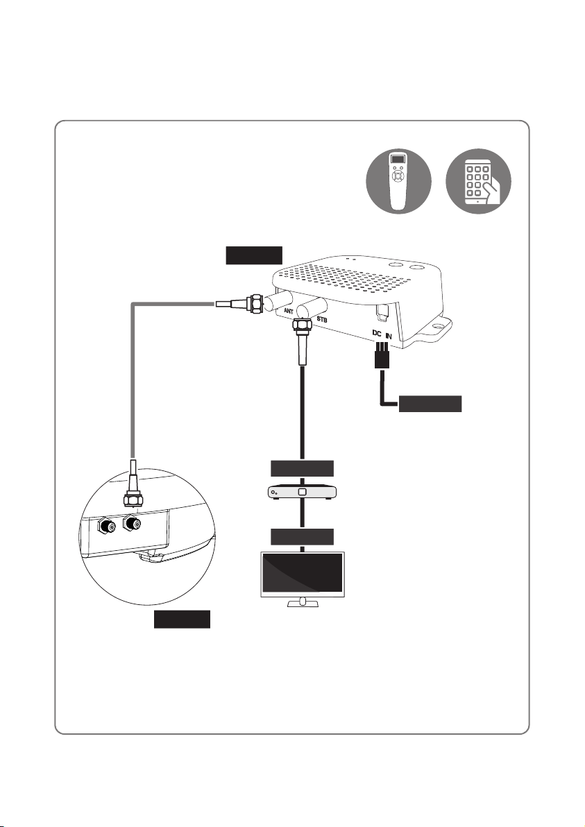
3. Operating Instruction
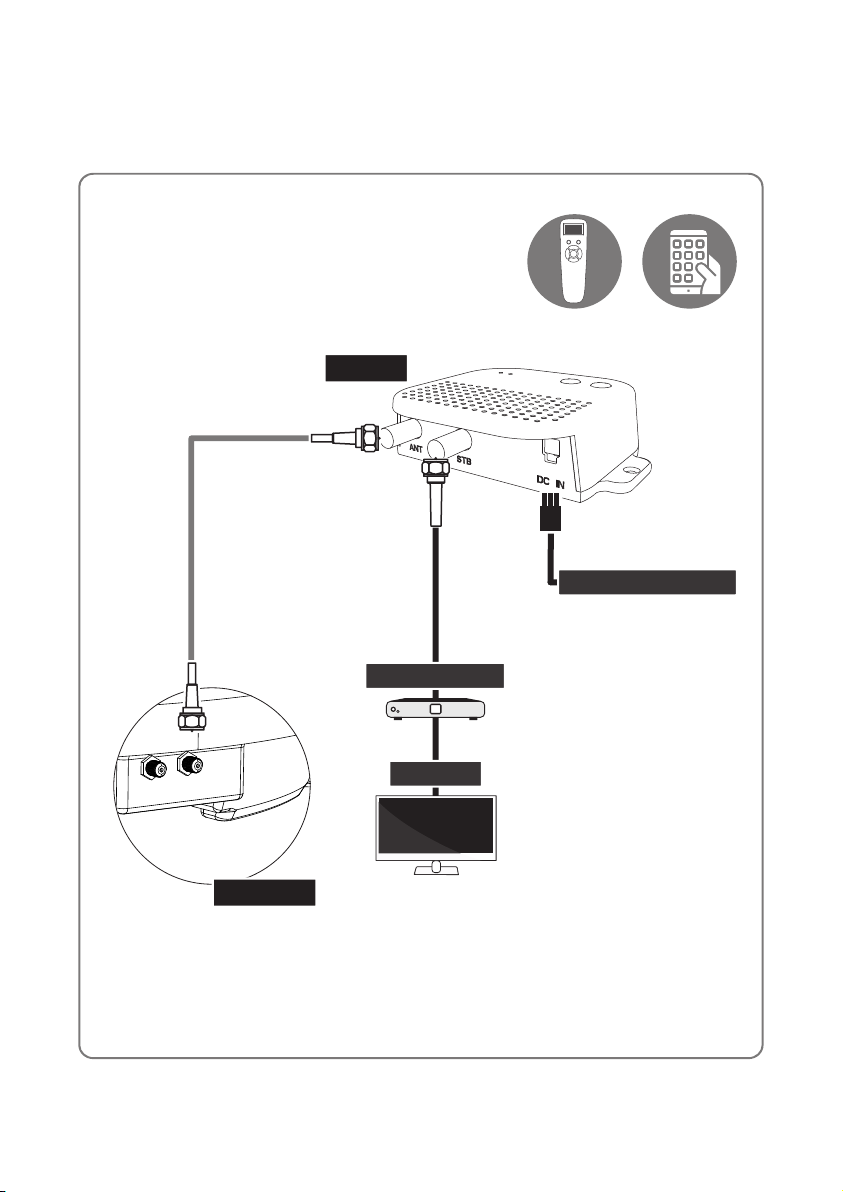
3-1. Connection diagram
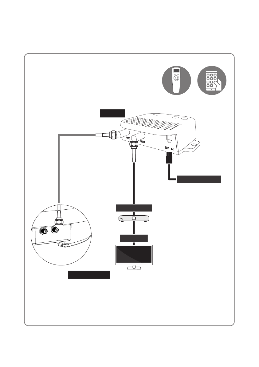
PI box
Remote control Mobile App
Power input cable
Cigar jack
Signal cable (10 m)
MAIN UNIT
PI cable (1.5 m)
STB
TV
Turn on the PI power after all cables connections are complete.
When not using the antenna, turn o the PI power.
ENGLISH - 6
Page 8
3-2. Functional description
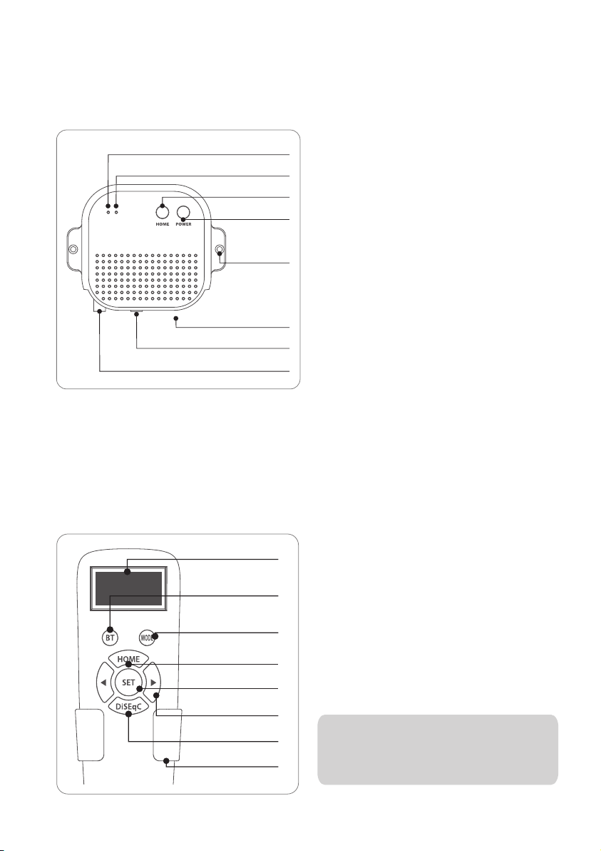
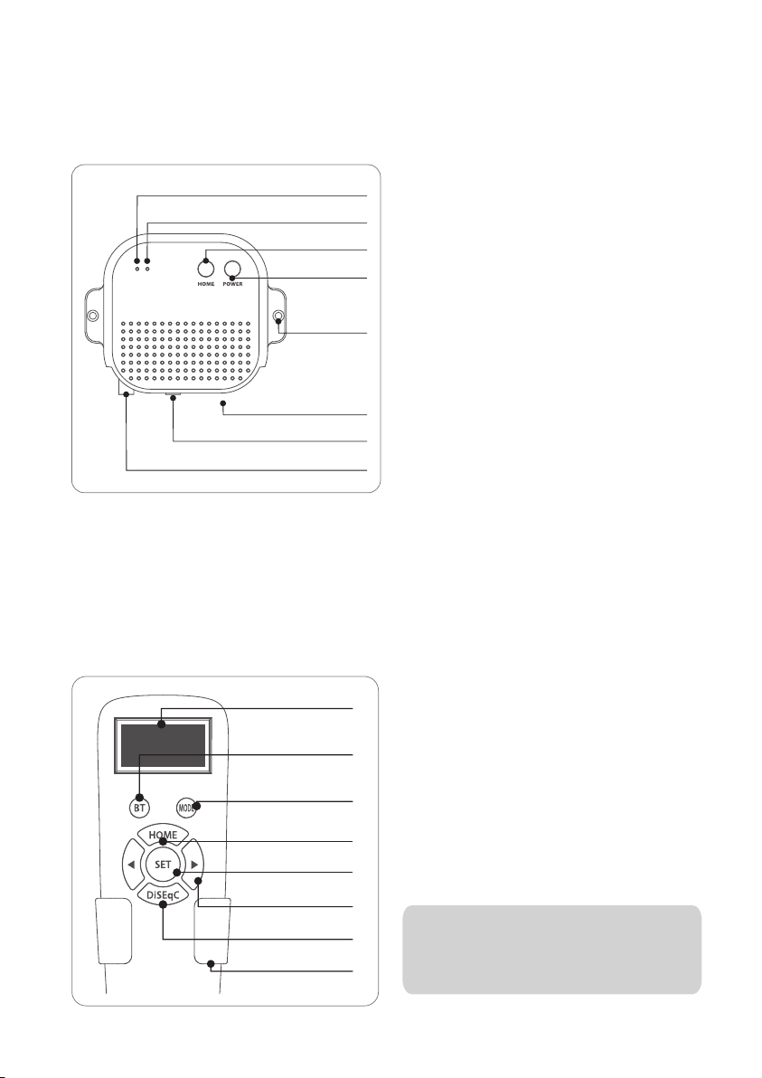
1. PI box
STB LED
POWER LED
HOME button
POWER button
Fixed hole
Power
to STB
to unit
B. Basic Features
i. Power save mode
When receiving a broadcast signal or when the antenna is in the home position, the antenna
a.
operates only with the current from the receiver
When searching for a satellite or when the antenna moves, it automatically changes to the power
b.
connected to DC power adapter
A. Button and LEDs
i. POWER Button
Press the POWER button to turn on the PI
a.
box, and power to the antenna unit.
(Power LED ON)
Press and hold for more than 3 seconds to
b.
turn off the power. (Power LED OFF)
ii. HOME Button
When the Home button is pressed, the
a.
antenna moves to the home position
iii. STB LED
When the power of the set-top box
a.
connected to the PI box is turned on, the
STB LED turns ON
2. Remote control
Display window
BT button
Pairing antennas
with remote controls
Mode button
HOME button
SET button
Arrow button
DiSEqC button
Bracket
A. Button and Display
i.
ii.
ENGLISH - 7
When not used for more than 1 minute, it
enters the power saving mode. (When the
battery is inserted in the remote control)
To return from sleep mode, press any button
except DiSEqC button
‘HOME’ or 'Home position' refers to
※
the Standby position for the antenna
to search for satellites.
Page 9
B. Basic Features
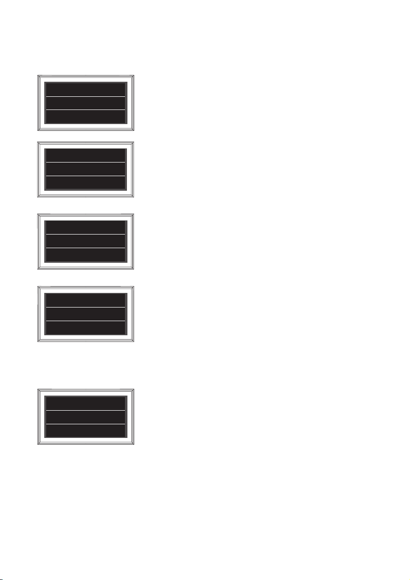
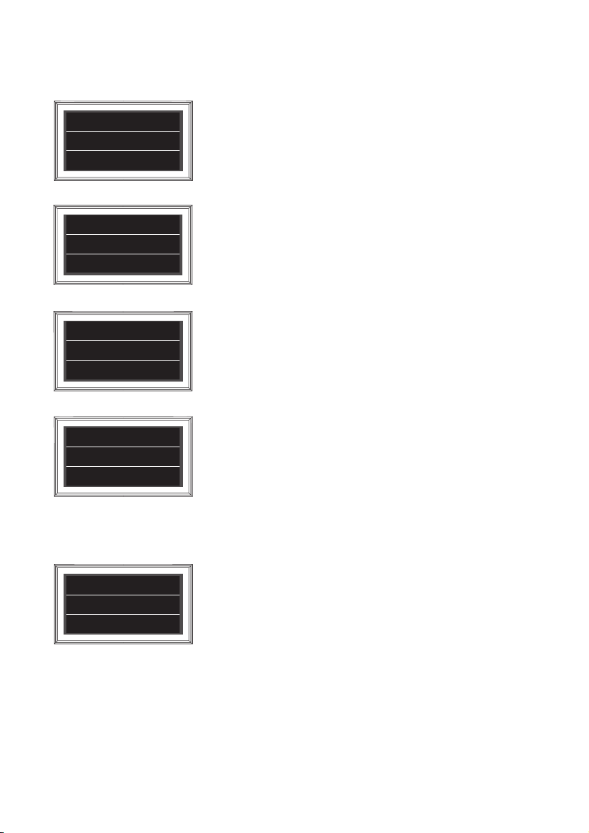
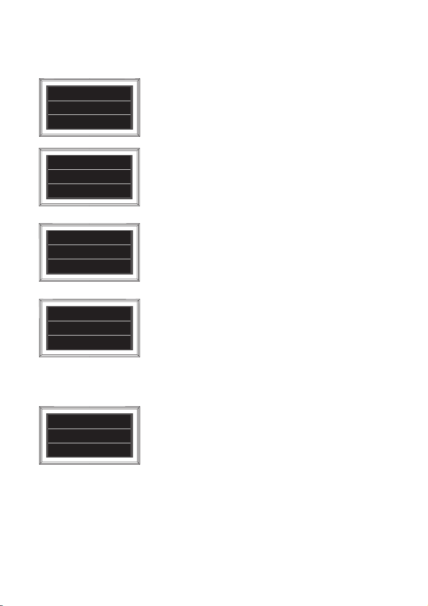
CONNECTING
Remote control
Version : 00
SELECT MAC
O - 09 : 39 : E4
PRESS SET
O - 39 : E4
Connected
O - 39 : E4
ASTRA 1
Home
The remote control automatically searches for nearby antenna unit.
If there is an antenna that has been connected before, connect it
immediately
When use antenna and remote control for the first time or when you
delete the antenna list stored in the remote control, a list of products that
can be connected will appear.
Press the left and right buttons on the remote control to select the MAC
Address of your antenna unit, and press the SET button to connect to the
remote control
When the remote control and the antenna are connected, a ‘Connected’
message appears.
The MAC Address of the connected antenna, the satellite name set for
the antenna, and the current status are displayed.
Press the left or right arrow button to select the desired satellite and
press the SET button to search for the satellite.
HOME - When the antenna is in the home position
Searching - When the antenna is searching for satellites
Found SAT - When the satellite search is complete
Mov To Home - the antenna will move to the home position.
O - 39 : E4 D
DiSEqC ON
Found SAT
Pressing the DiSEqC button changes the DiSEqC settings of antenna unit.
DiSEqC mode is indicated by [D] mark in the first line.
ENGLISH - 8
Page 10
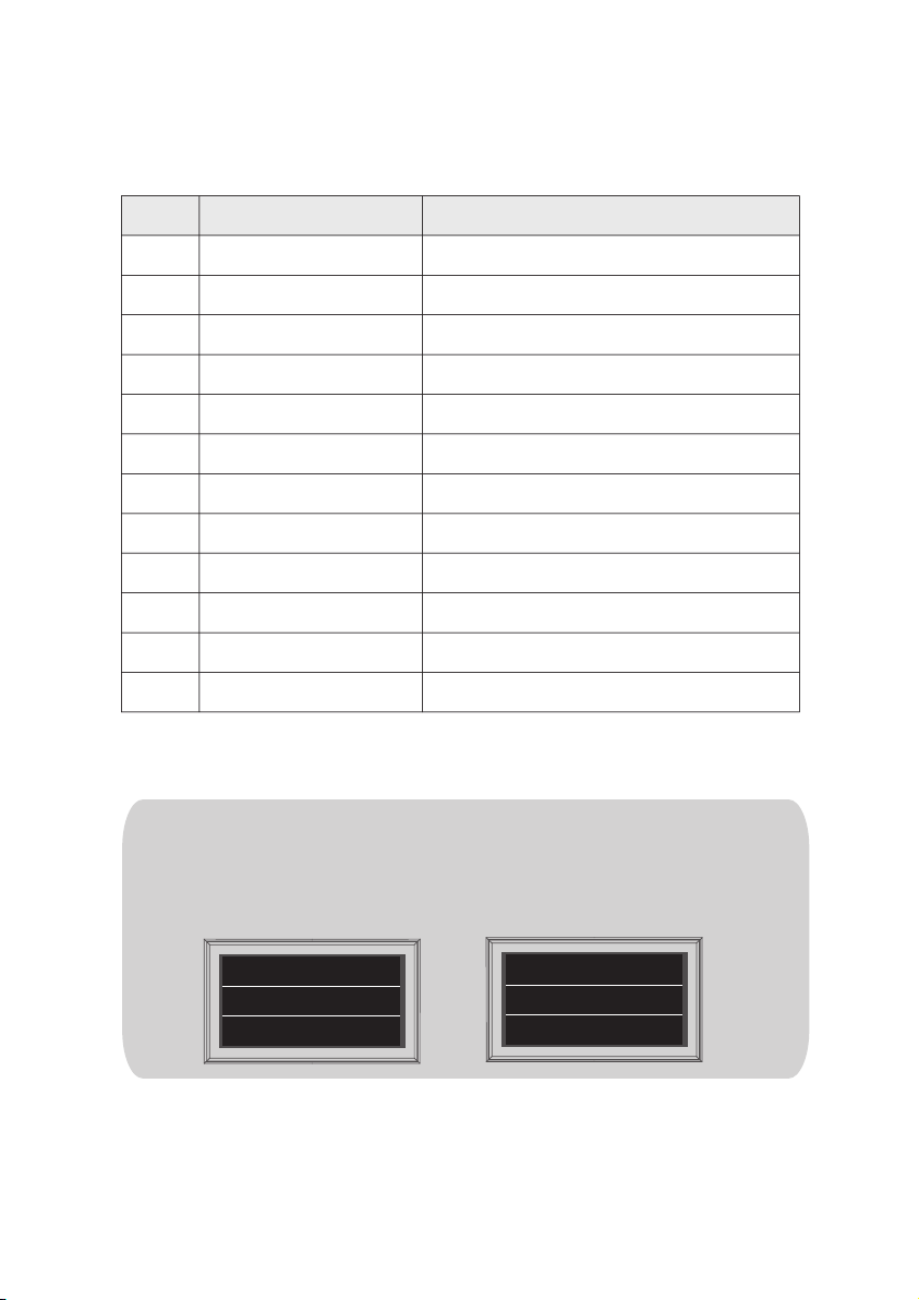
i. DiSEqC setting
Refer SNIPE DOME 2’s pre-satellites for DiSEqC 1.1 when user setup at STB
NO
1
2
3
4
5
6
7
8
9
10
11
12
For DiSEqC operating, user needs to assign DiSEqC satellites list at STB is in same order as above
SNIPE DOME 2’s pre-set list
The DiSEqC function is disabled when the antenna is in the HOME position.
※
LNB
LNB 1
LNB 2
LNB 3
LNB 4
LNB 5
LNB 6
LNB 7
LNB 8
LNB 9
LNB 10
LNB 11
LNB 12
Satellite
ASTRA1
ASTRA2
ASTRA3
ASTRA1
Hot Bird
Eutelsat 9
ASTRA 4
Thor
Eutelsat 5W
ASTRA1
USER1
USER2
To use DiSEqC, press the DiSEqC button to activate the function when the
message 'Searching' or 'Found SAT' to appear on the remote control screen.
(ex)
OK NO
O - 39 : E4
ASTRA 1
Searching
ENGLISH - 9
O - 39 : E4
ASTRA 1
Home
Page 11
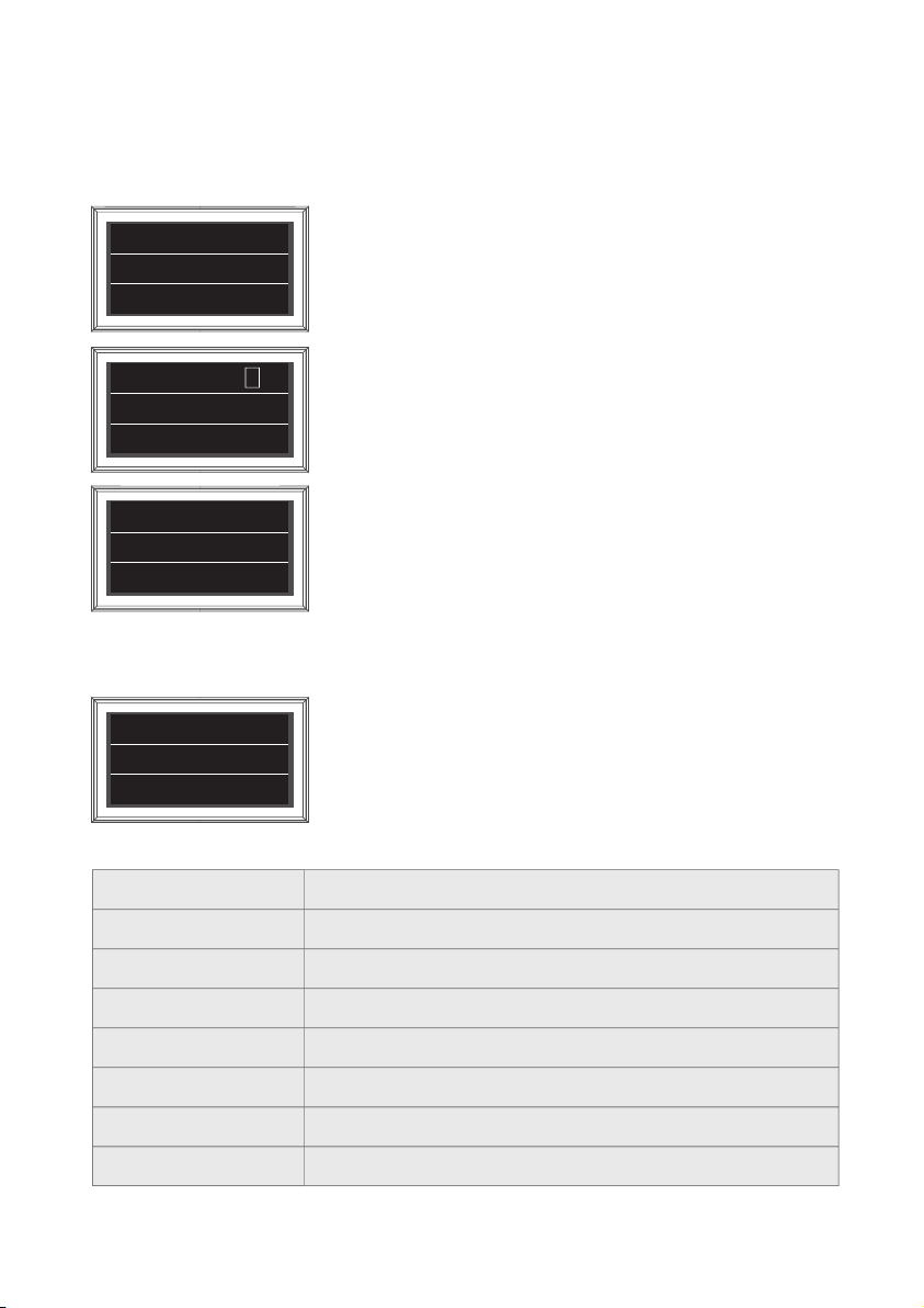
C. Additional settings
BT button
i.
Press BT button to change to BT setting screen. Press the arrow to move to the desired function
a.
and set with the SET button
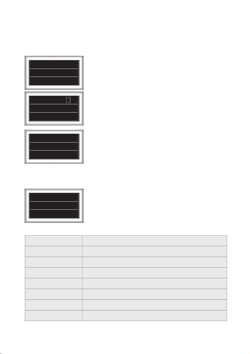
BT SET
REMOVE MAC
Delete the MAC Address of antenna stored in the remote control.
Used to connect to other products
PRESS SET
BT SET
REFIND ON
PRESS SET
BT SET
R
Research function can be turned on / off.
The research function is a function that automatically moves the antenna
to the position of the last received satellite signal when the receiver is
turned on.
When the Research function is turned on, [R] mark in the first line
Used to update the remote control firmware.
Press the SET button to restart the remote control in update mode
R/C Update
PRESS SET
Press and hold BT button for more than 5 seconds to reset the remote controlb.
D. Error message
O- 39 : E4 D
ASTRA 1
If an error occurs during operation, the error number appears with the
error statement.
Error 6F
The errors message are shown in the table below.
0x00
Not indicated
0x6A
0x6B
0x6C
0x6E
0x6F
0x70
0x71
Home position
AZ Motor movement
EL Motor Movement
NID Check fail
Tuner lock fail
EL Up LIMIT Error
EL Down LIMIT Error
ENGLISH - 10
Page 12

3-3. Quick reference
1.
Turn on the remote control and select the unit that matches the MAC Address of your
antenna.
2.
Use the left and right arrow buttons to select the satellite and press the SET button.
3.
Wait for the message 'FOUND SAT' to appear on the remote control screen.
4.
When the satellite search is complete, watch the broadcast.
NOTE
In order to ensure that your SNIPE DOME 2 works properly you must
ensure that it is following by the Operating Instructions in this manual
and used as intended purpose.
If the system cannot fully be removed due to user's negligence, then it is
your responsibility to check that the antenna is properly stored in safe.
Please also note that different legal requirements are applied to the
operation of electrical and electronic equipment in different countries.
As the user of this equipment, you are responsible for yourself ensuring
compliance with the relevant laws and regulations. The manufacturer
does not take liability for direct or indirect consequential damage of the
system, motor vehicles or other equipments by reason of unsuitable
battery usage or erroneous installation or wrong wire connection.
4. Software Upgrade
4-1. Upgrade via the app
Download and install the Sat Connect app from the App store
a.
Turn on the antenna power (Turn on the receiver power and PI box)
b.
Connected the application with the antenna
c.
Select FW UPGRADE from the menu to update the antenna
d.
UPGRADE takes about 5 minutes
e.
ENGLISH - 11
Page 13

5. Troubleshooting
There are a number of common issues that can affect the signal reception quality or
the operation of the unit. The following sections address these issues and potential
solutions.
A. No function when power on the antenna
i.
Check again all the cable connections have been made correctly.
-
Connection between the power and the PI box.
-
Connection between the PI box and antenna.
Check if the power input cable has been damaged.
ii.
Check the battery polarities (+/-).
iii.
Check if the PI Box is powered on (Check Power LED of PI BOX is on)
iv.
B. The remote control does not turn on
Try pressing any button other than the DiSEqC button.
i.
Check if the battery is properly inserted.
ii.
Check if the remote control's battery is exhausted.
iii.
C. Fail to search the selected satellite
Satellite signals can be blocked or degraded by buildings, trees.
i.
Make sure there are no obstructions in a southward direction.
Select another satellite as example Astra3, if this locks then select your desired satellite. ie Astra1.
ii.
Turn the unit off and then back on again and select desired satellite.
iii.
D. Mechanical problems
i.
If the antenna does not move into desired position.
-
Try to power OFF/ON again.
ii.
If the antenna makes a noise whilst remaining static.
-
Try to power OFF/ON again. If problem persists, please contact local dealer/shop for assistance.
E. Other issues
i.
If the system has been improperly wired, it will not operate properly. Contact local dealer/shop
for assistance of cable damage.
ENGLISH - 12
Page 14
6. Specications
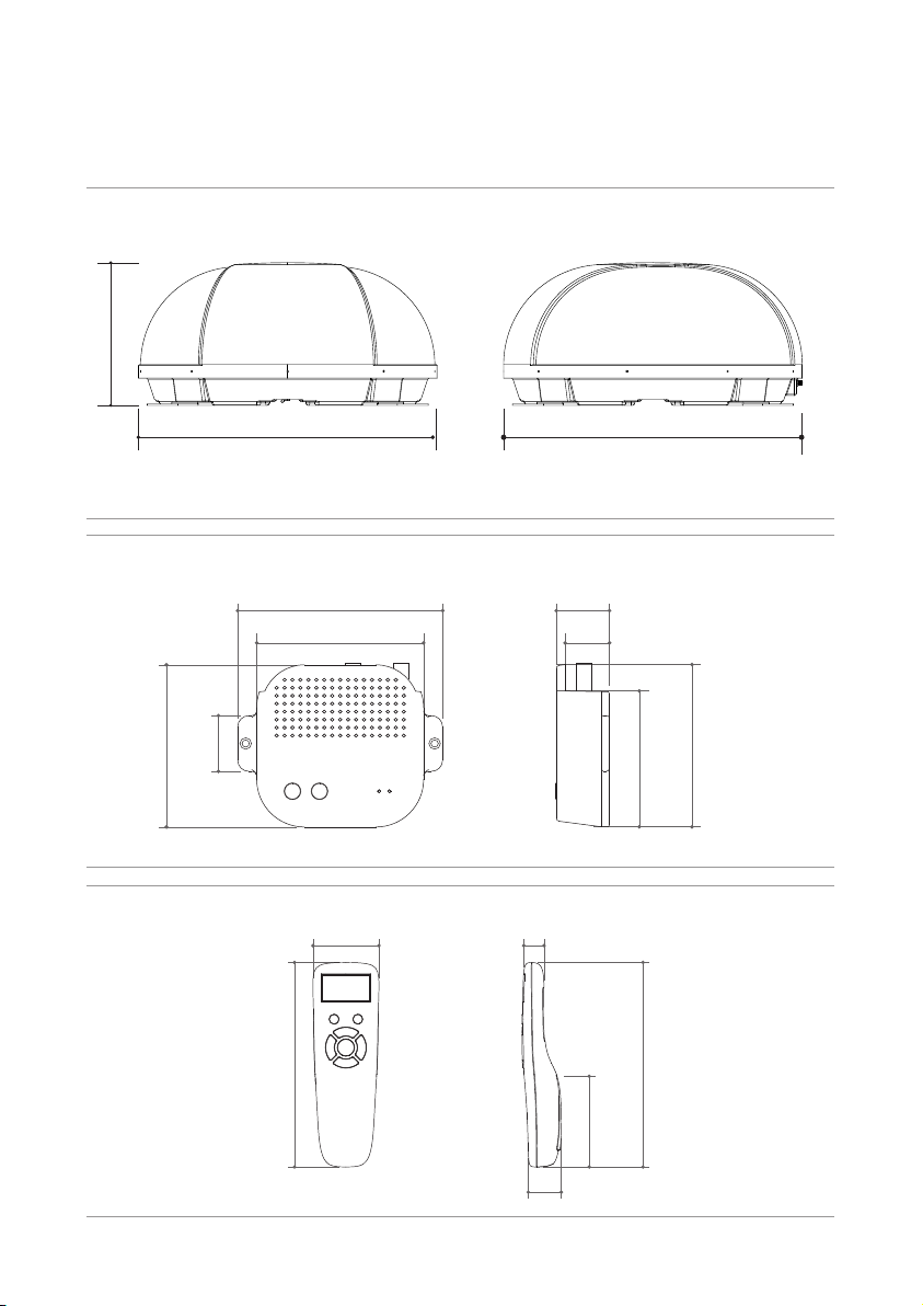
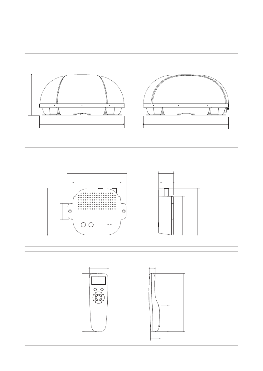
6-1. Dimension
SNIPE DOME 2
31.5cm
66.0cm 66.0cm
PI box
102 mm
35 mm
Remote control
155 mm
129 mm
105 mm
15 mm50 mm
25 mm
34 mm
28 mm
69 mm
85mm
155 mm
102 mm
ENGLISH - 13
Page 15

6-2. Specications
Model
Input Frequency
Polarization
Antenna Gain
Size (W x D x H)
Weight
Min EIRP
Angle Range (EL / AZ )
Satellite Switching System
Satellite Searching Time
Output
LNB
Input Voltage
Power Consumption
Model
Frequency
Support Bluetooth version
BLE Gain
Size (W x D x H)
Screen size (L X H)
Battery
Output Frequency
L.O. Frequency
TX power
RX sensitivity
SNIPE DOME 2
10.7 ~ 12.75 GHz
Vertical & Horizontal
33.7 dBi @ 12.7 GHz
(ANT) 660 x 660 x 315 mm
(ANT) 9.6 kg / (RCU) 23 g
50 dBW
15° ~ 75° / 390°
DiSEqC
180 seconds (average)
1 / 2 output (optional)
950 ~ 2,150 MHz
9.75 / 10.6 GHz
DC 12 V
30 W (in searching)
SNIPE DOME 2 Remote control
2.4 GHz
Ver 4.2 / 5.0 (the latest)
up to +3 dBm
down to -92 dBm
140 X 50 X 18 mm
128 X 64 Pixels
AAA X 2
ENGLISH - 14
Page 16
7. Installation
7. Caravan/Motorhome Installation
7-1. Precaution before installation
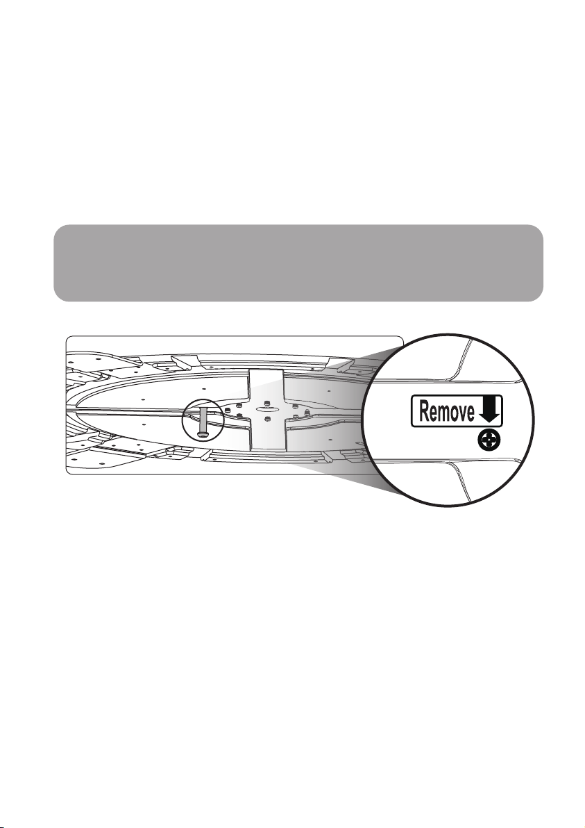
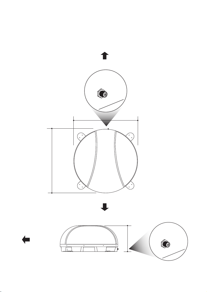
The product is shipped with internal lock for protecting the unit and preventing damage
while transportation.
Prior to the installation, remove the locking bolt in the bottom of the product, which is
indicated with “Remove (allow mark)” sticker (please refer to the below image)
Do not open the antenna cover to remove bolt.
Warning
Be aware that using antenna before removal the internal lock bolt will damage the antenna
so make sure to read this manual and precautions thoroughly before installation to prevent
damage to the product.
ENGLISH - 15
Page 17
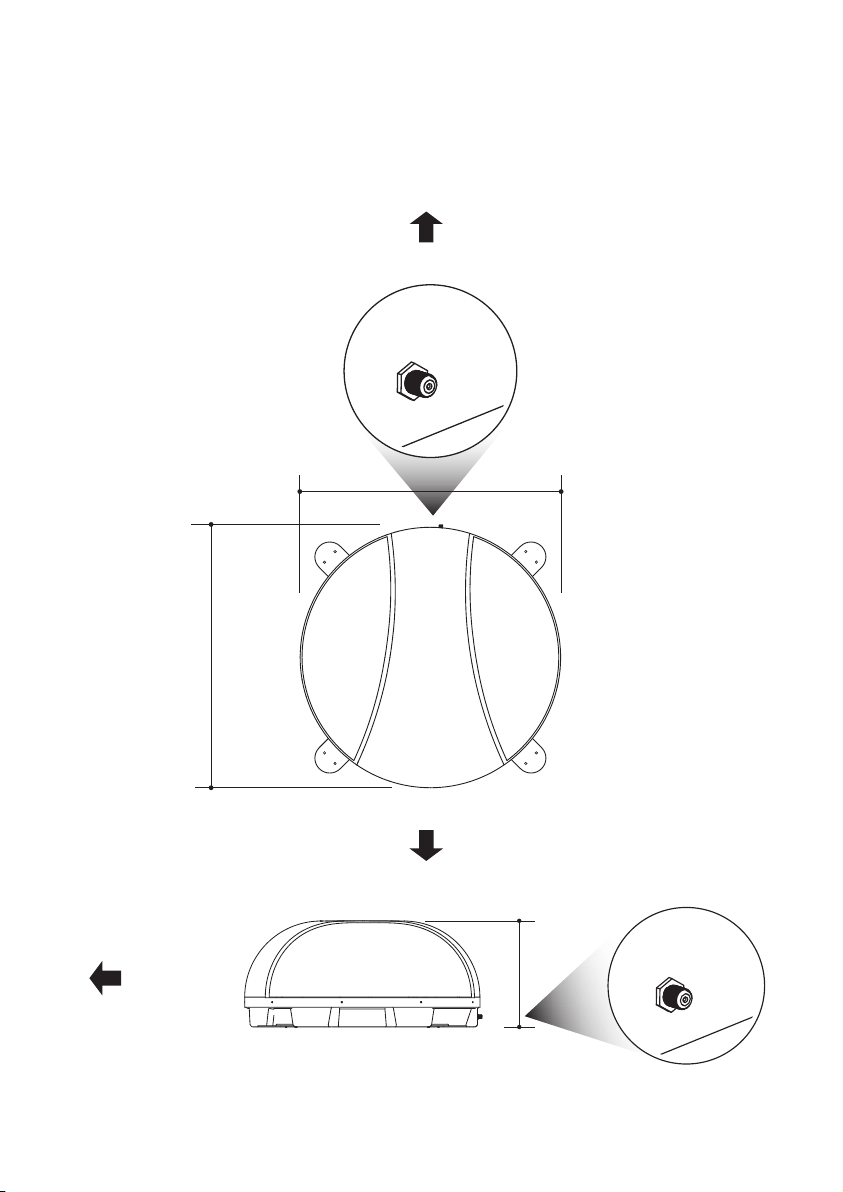
7-2 . Required space for SNIPE DOME 2
Take care, that there is enough space for the SNIPE DOME 2, just as for the operation range.
Veh ic le re a r
66.0cm
66.0cm
Driving direction
Driving direction
31.5cm
ENGLISH - 16
Page 18
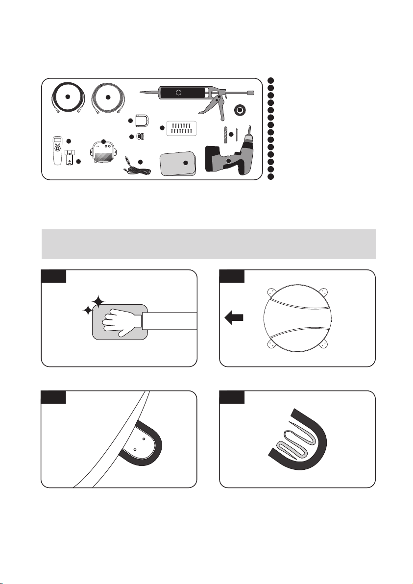
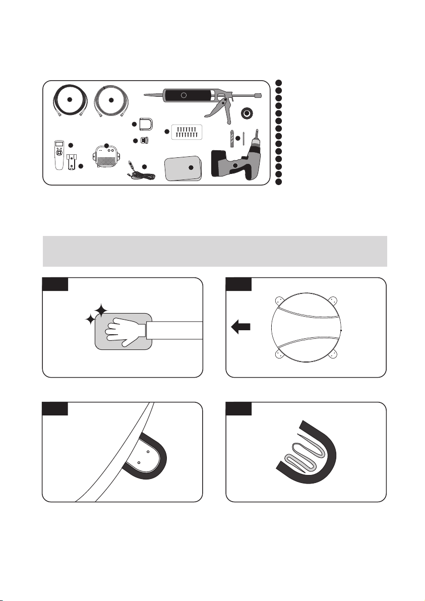
7-3. Equipment for installation
10
5
12
13
11
6
7
9
14
1
8
3
5
7-4. Instruction for installation
A. SNIPE DOME Installation on the vehicle roof
(same for all 4 mounting plate edges)
1
Silicone
2
Masking tape
3
Cleaner
4
2
4
2mm drill bit, over 20mm drill bit
5
Power drill
6
Cable holder
7
Cable gland
8
M4 ×20(15)
9
PI box
10
PI cable (1.5m)
11
Signal cable (10m)
12
Remote conteol
13
Remote conteol bracket
14
Cigarette lighter adaptor (Power input cable)
A-1
Clean the surface with cleaner
A-3
Attach masking tape outside of the mounting
plate, to be 4mm away from the plate edge
A-2
FRONT
Locate the antenna in the center of car roof
A-4
Put aside the antenna to apply silicone inside
the guided tape line
ENGLISH - 17
Page 19
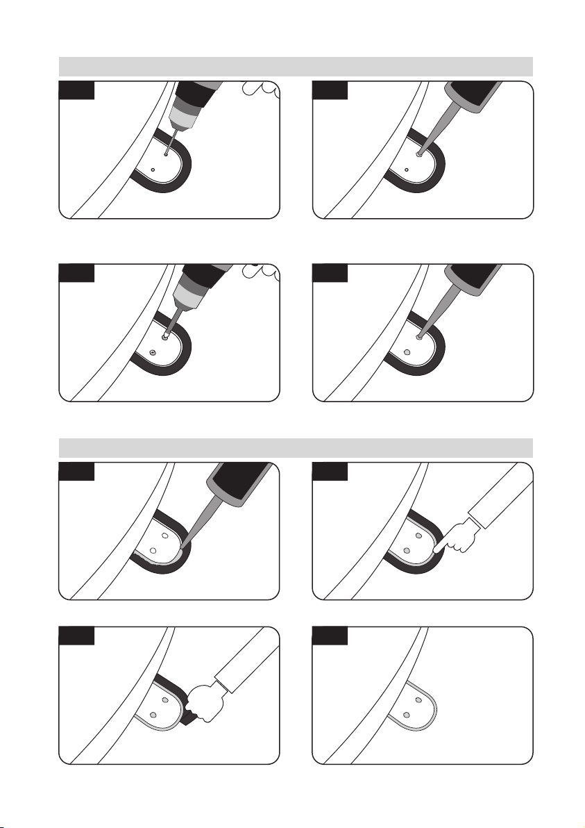
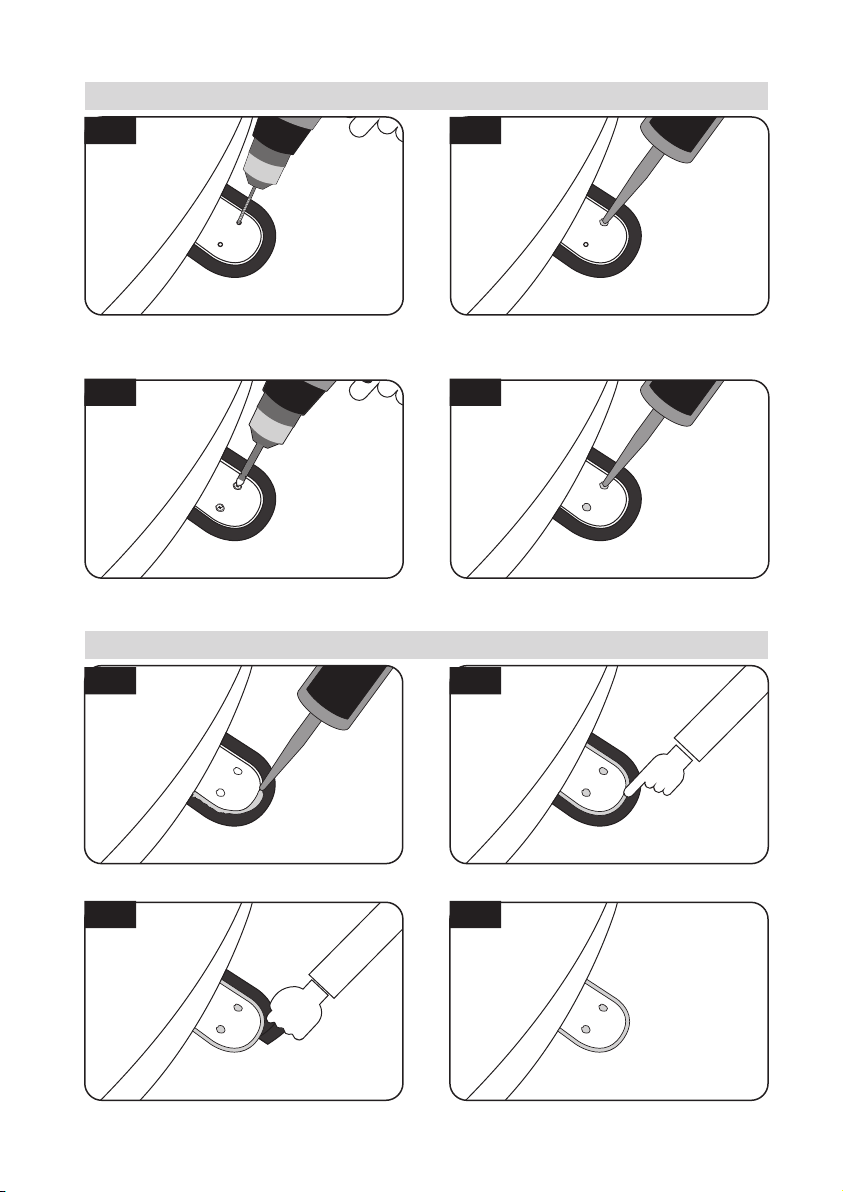
B. Assemble 2pcs of M4x20 bolt to fix the four(4) mounting plates each
B-1
B-2
Place main unit on the top of fixed plate. Put back
the mounting plate on the silicone applied and
two(2)
make
holes (2mm) with power drill
B-3
7
Assemble mounting plate using two(2) M4x20
screws
Apply silicone on the holes
B-4
8
Re-apply silicone to cover tightened screws
C. Apply silicone between mounting plate and masking tape
C-1
Apply silicone around mounting plate edges
C-2
Tidy silicone surface
C-3
Remove masking tape and allow to dry
C-4
Repeat the same for the remaining mounting
plates
ENGLISH - 18
Page 20
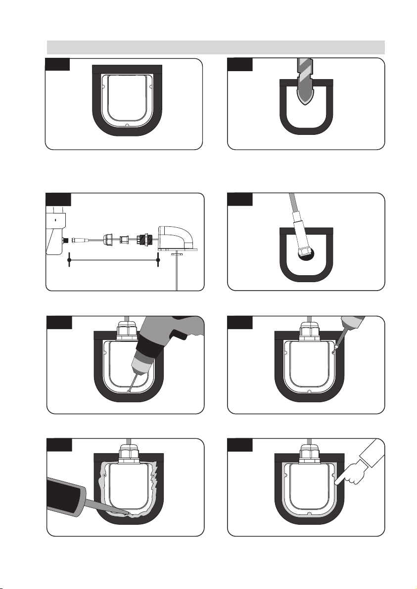
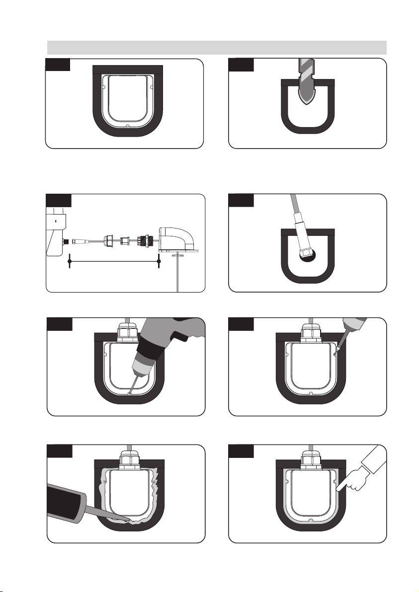
D. Cable holder installation
D-1
Arrange cable holder in front of (30cm apart
from) antenna center by facing open side of
cable holder. Then attach masking tape
outside of cable holder
D-3
approx. 30cm
Set up the signal cable, cable holder and cable
gland as above picture
D-5
D-2
Apply masking tape 5mm from away the
outside of holder and drill a 20mm hole in the
center to allow the cable can pass through.
D-4
Insert the signal cable through the hole
D-6
Place the assembled cable holder inside the tape
marking and drill three(3) of 2mm holes
Apply silicone around cable holder and on the
top of screws for waterproof
ENGLISH - 19
Fix cable holder on the vehicle roof with
three(3) of M4 x 20 screws on drill holes made
D-8D-7
Connect cables to the ports of the antenna ,
remove masking tape and tidy silicone before dry
Page 21
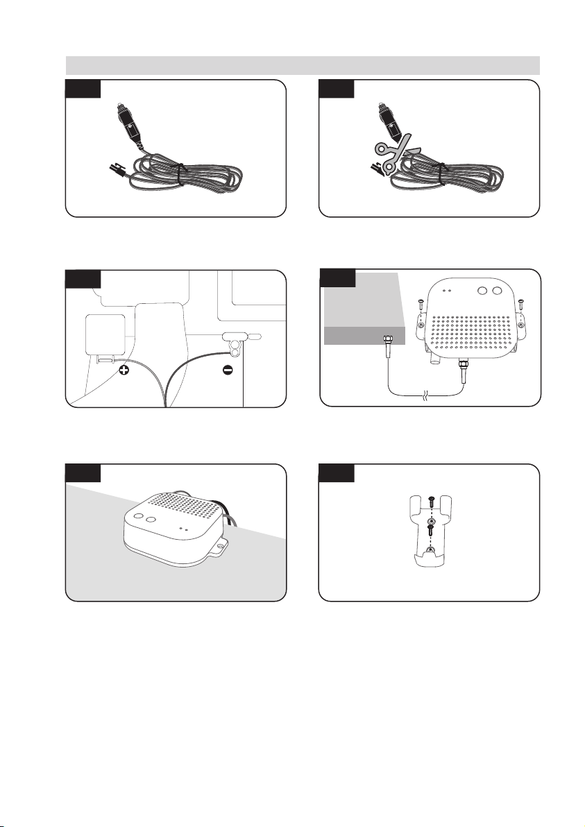
E. PI box and Remote control installation
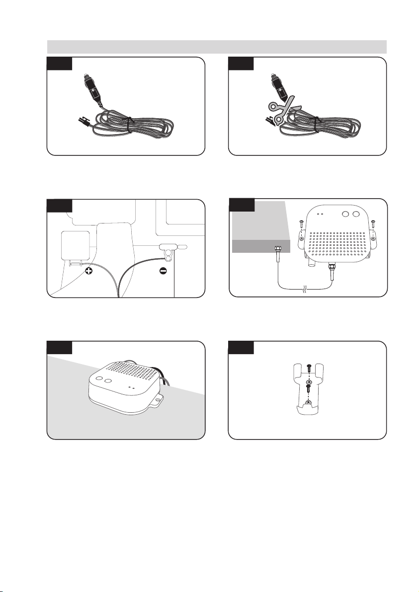
E-1
E-2
Get Power input cable and plug into cigar
lighter socket (12V outlet)
E-3
12V DC
Match the power cables polarities to the
battery polarities, red to red / black to black
ports of the vehicle
E-5
Connect power, PI box and receiver using
cigarette lighter adaptor and PI cable
To source power from car battery, cut off
cigar-jack connector to take inner three cables
out and peel off each to take copper cable out
E-4
STB
approx.1.5m
Fix PI Box where it should be fixed using two(2)
of M4x20 screw
E-6
Fix Remote control bracket where it should be
fixed using two(2) of M4x20 screw
ENGLISH - 20
Page 22

Page 23

Inhaltsverzeichnis
1. Allgemeine Informationen
1-1. Produktvorstellung
1-2. Bestimmungsgemäße Verwendung
1-3. Sicherheitshinweise
2. Verpackungsinhalt
2-1. Lieferumfang
2-2. Bezeichnung der Teile
3. Bedienungsanleitung
3-1. Anschlussplan
3-2. Funktionsbeschreibung
3-3. Kurzanleitung
...................................................................................
...................................................................................
.........................................................................................
................................................................................
.........................................................................................
...............................................................................
..........................................................................................
..................................................................
2
2
3
4
5
6
7
11
4. Software-Upgrade
5. Fehlerbehebung
..............................................................................
................................................................................
6. Technische Daten
6-1. Abmessungen
6-2. Technische Daten
.........................................................................................
.....................................................................................
7. Installation von Wohnmobil/Reisemobil
7-1. Vorsichtsmaßnahme vor der Installation
7-2. Erforderlicher Platz für Installation
7-3. Ausrüstung für die Installation
7-4. Installation
...........................................................................................
........................................................................
.............................................................
....................................................................
11
12
13
14
15
16
17
17
Page 24
1. Allgemeine Informationen
1-1. Produktvorstellung
Die Bedienungsanleitung beschreibt die Funktion und die Bedienung, selbstnachführenden
Satelliten-Systems SNIPE DOME 2. Der korrekte und sichere Betrieb des Systems ist nur
gewährleistet, wenn die Bedienungsanleitung befolgt wird.
Ihre SNIPE DOME 2 ist ein intelligentes Satelliten-TV-Empfangssystem, das sich automatisch
auf die gespeicherten Satelliten ausrichten kann, solange es sich in der Ausleuchtzone
befindet.
Im allgemeinen Betrieb stellen Sie bitte sicher, dass das System immer eine ungehinderte
Sicht auf den Himmel hat. Wenn das direkte Satelliten-Signal durch Hindernisse wie Berge,
Gebäude oder Bäume unterbrochen wird, kann das Gerät nicht funktionieren und kein
TV-Signal kann empfangen werden.
Die ersten Seiten der Bedienungsanleitung enthalten Informationen über die allgemeinen
Funktionen Ihrer SNIPE DOME 2, gefolgt von der Erläuterung der möglichen Einstellungen.
Die letzten Seiten der Anleitung behandeln die technischen Aspekte der SNIPE DOME 2.
1-2. Bestimmungsgemäße Verwendung
Dieses Produkt wurde für den festen Einbau in Fahrzeuge mit einer Höchstgeschwindigkeit
von 130 km/h entwickelt. Es richtet seine Antenne vollautomatisch auf geostationäre TV-Satelliten aus. Das System kann mit einer Standard- Fahrzeugspannung von 12 oder 24 Volt DC
(Gleichstrom) versorgt werden.
Das vorliegende Produkt darf nur für den in dieser Anleitung beschriebenen Zweck verwendet werden.
DEUTSCH- 2
Page 25

Bitte beachten Sie auch die folgenden Hinweise des Herstellers:
•
Jede Änderung des Geräts durch Hinzufügen oder Entfernen von Teilen ist nicht gestattet.
•
Die Verwendung von anderen Bauteilen, als ursprünglich eingebaut, ist nicht gestattet.
•
Die Installation am Fahrzeug darf nur von qualifiziertem Fachpersonal durchgeführt werden.
•
Alle Anweisungen in der Montageanleitung, die separat mitgeliefert werden, müssen sorgfältig
befolgt werden.
•
Das Gerät bedarf keiner Wartung. Das Gehäuse des Geräts darf nicht geöffnet werden.
•
Überprüfung und Wartung sollte immer durch eine qualifiziertes Fachpersonal durchgeführt
werden.
•
Alle relevanten und vorgeschriebenen Richtlinien der Automobilindustrie müssen beachtet
werden.
•
Das Gerät darf nur auf Hartschalendächern installiert werden.
•
Vermeiden Sie Ihr Fahrzeug mit dem montierten Satellitensystem in Bürstenwaschanlagen,
Waschstraßen oder mit Hochdruckreinigern zu reinigen.
1-3. Sicherheitshinweise
Um einen einwandfreien Betrieb der SNIPE DOME 2 zu gewährleisten, müssen Sie sich
vergewissern, dass alle Komponenten gemäß der vorliegenden Anleitung angeschlossen
sind und wie vorgesehen verwendet werden.
Stellen Sie bei der Installation von SNIPE DOME 2 sicher, dass die Installation mit den
mitgelieferten Kabeln erfolgt und dass die Kabel in keiner Weise verändert werden.
Bitte beachten Sie auch die unterschiedlichen gesetzlichen Bestimmungen für den
Betrieb elektrischer Geräten im Ausland.
Sie, als Nutzer des Geräts, übernehmen die Verantwortung dafür, das Gerät in Einhaltung
der relevanten Gesetze und Vorschriften zu betreiben.
Der Hersteller haftet nicht für direkte oder indirekte Schäden an dem Gerät, Kraftfahrze-
ug oder anderen Geräten, die durch den Anschluss an ungeeigneten Stromquellen,
falscher Montage oder falscher Verkabelung entstanden sind.
DEUTSCH- 3
Page 26
2. Verpackungsinhalt
2-1. Lieferumfang
Haupteinheit PI box
KabelhalterFernbedienungshalterung
PI-Kabel - 1,5 m
M4 ×20(15)
Die tatsächlichen Komponenten können sich von den obigen Bildern unter-
※
Signalkabel - 10m
(x2 für optionale 2 Ausgänge)
Bedienungsanleitung Netzteil
Fernbedienung
Kabelverschraubung
Stromversorgungskabel
(Zigarettenanzünder-Kabel)
(Optional)
scheiden.
Das Gerät kann mit einer Autobatterie versorgt werden. Um ein Kabel für die
※
Stromversorgung herstellen, schneiden Sie den Zigarettenanzünder ab und
entfernen die Isolierung der Kupferkabel.
Nur ein Netzteil des Herstellers der SNIPE Serie stellt die korrekte Funktion sicher
※
und sollte verwendet werden.
Netzteil muss separat erworben werden. Bitte fragen Sie lokalen Händler/Laden
※
für weitere Informationen.
DEUTSCH- 4
Page 27
2-2. Bezeichnung der Teile
Haupteinheit
Antenne
zu PI-box ("ANT" Port)
Montageplatte
PI-box Fernbedienung
zu empfänger (optional)
STB LED
POWER LED
HOME-Taste
POWER-Taste
Befestigungsloch
Power
zu empfänger
Zur Haupteinheit
DEUTSCH- 5
Anzeige
BT -Taste
Koppeln Antenne mit
Fernbedienung
Mode -Taste
Home-Taste
Set-Taste
Pfeiltaste
DiSEqC-Taste
Halterung
Page 28
3. Bedienungsanleitung
3-1. Anschlussplan
PI-box
Fernbedienung Mobile Applikation
Stromversorgungskabel
Zigarettenanzünder
Signal-kabel (10m)
PI-kabel(1.5 m)
STB (Empfänger)
Fernseher
Haupteinheit
* Schalten Sie den PI-box, nachdem alle Kabel Verbindungen hergestellt sind.
* Wenn die Antenne nicht verwendet wird, schalten die PI-box ausgeschaltet.
DEUTSCH- 6
Page 29
3-2. Funktionsbeschreibung
1. PI-box
STB LED
POWER LED
HOME-Taste
POWER-Taste
Befestigungsloch
Power
zu empfänger
Zur Haupteinheit
B. Grundfunktionen
i. Energiesparmodus
Wenn Sie ein Sendesignal empfangen oder wenn sich die Antenne in der Ausgangsposition
a.
befindet, Die Antenne arbeitet nur mit dem Strom vom Empfänger
Bei der Suche nach einem Satelliten oder wenn sich die Antenne bewegt, Es wechselt automa-
b.
tisch zur Stromversorgung des Gleichstromadapters
A. Taste und LEDs
i. POWER -Taste
Drücken Sie die POWER-Taste, um die
a.
PI-Box einzuschalten und die Antenneneinheit mit Strom zu versorgen. (Power LED
EIN)
Halten Sie die Taste länger als 3 Sekunden
b.
gedrückt, um das Gerät auszuschalten.
(Power LED AUS)
ii. HOME -Taste
Wenn die Home-Taste gedrückt wird,
a.
bewegt sich die Antenne in die HomePosition
iii. STB LED
Wenn die Stromversorgung der an die
a.
PI-box angeschlossenen Empfänger
eingeschaltet wird, leuchtet die STB-LED
auf
2. Fernbedienung
Anzeige
BT -Taste
Koppeln Antenne mit
Fernbedienung
Mode -Taste
Home-Taste
Set-Taste
Pfeil-Taste
DiSEqC-Taste
Halterung
A. Taste und Anzeige
i.
ii.
DEUTSCH- 7
Wenn es länger als 1 Minute nicht verwendet wird, wechselt es in den Energiesparmodus. (Wenn der Akku in die Fernbedienung
eingelegt ist)
Um aus dem Ruhemodus zurückzukehren,
drücken Sie eine beliebige Taste außer der
DiSEqC-Taste
”HOME” oder “Home Position" bezieht
※
sich auf die Standby-Position der
Antenne, um nach Satelliten zu suchen.
Page 30
B. Grundfunktionen
CONNECTING
Remote control
Version : 00
SELECT MAC
O - 09 : 39 : E4
PRESS SET
O - 39 : E4
Connected
O - 39 : E4
ASTRA 1
Home
Die Fernbedienung sucht automatisch nach einer Antenneneinheit in
der Nähe.
Wenn zuvor eine Antenne angeschlossen wurde, schließen Sie diese
sofort an
Wenn Sie Antenne und Fernbedienung zum ersten Mal verwenden oder
wenn Sie die in der Fernbedienung gespeicherte Antennenliste löschen,
wird eine Liste der Produkte angezeigt, die angeschlossen werden
können.
Drücken Sie die linke und rechte Taste auf der Fernbedienung, um den
MAC Address Ihrer Antenneneinheit auszuwählen, und drücken Sie die
SET-Taste, um eine Verbindung zur Fernbedienung herzustellen
Wenn die Fernbedienung und die Antenne verbunden sind, wird die
Meldung ‘Connected’ angezeigt
Der MAC Address der angeschlossenen Antenne, der für die Antenne
festgelegte Satellitenname und der aktuelle Status werden angezeigt.
Drücken Sie die linke oder rechte Pfeiltaste, um den gewünschten
Satelliten auszuwählen, und drücken Sie die SET-Taste, um nach dem
Satelliten zu suchen
HOME - Wenn sich die Antenne in der Ausgangsposition befindet
Searching - Wenn die Antenne nach Satelliten sucht
Found SAT - Wenn die Satellitensuche abgeschlossen ist
Mov To Home - Die Antenne bewegt sich in die Ausgangsposition
O - 39 : E4 D
DiSEqC ON
Found SAT
Durch Drücken der DiSEqC-Taste werden die DiSEqC-Einstellungen der
Antenneneinheit geändert.
Der DiSEqC-Modus wird in der ersten Zeile durch die Markierung [D]
angezeigt
DEUTSCH- 8
Page 31

i. DiSEqC-Einstellung
Siehe SNIPE-Vor-Satelliten für DiSEqC 1.1 bei der Benutzereinstellung von STB
NO
1
2
3
4
5
6
7
8
9
10
11
12
Fur den Einsatz von DiSEqC muss der Benutzer die DiSEqC-Satellitenliste bei STB zuordnen, sie ist
in der gleichen Reihenfolge wie die oben voreingestellte Liste von SNIPE DOME 2
Die DiSEqC-Funktion ist deaktiviert, wenn sich die Antenne in der Position
※
LNB
LNB 1
LNB 2
LNB 3
LNB 4
LNB 5
LNB 6
LNB 7
LNB 8
LNB 9
LNB 10
LNB 11
LNB 12
Satellite
ASTRA1
ASTRA2
ASTRA3
ASTRA1
Hot Bird
Eutelsat 9
ASTRA 4
Thor
Eutelsat 5W
ASTRA1
USER1
USER2
HOME befindet.
Zur Nutzung DiSEqC, drücken Sie die DiSEqC-Taste, um die Funktion zu
aktivieren, wenn die Meldung ‘Searching’ oder ‘Found SAT’ auf der
Fernbedienung Bildschirm angezeigt werden.
OK Nein
O - 39 : E4
ASTRA 1
Searching
O - 39 : E4
ASTRA 1
Home
DEUTSCH- 9
Page 32
C. Zusätzliche Einstellungen
BT -Taste
i.
Drücken Sie die BT-Taste, um zum BT-Einstellungsbildschirm zu wechseln. Drücken Sie den Pfeil,
a.
um zur gewünschten Funktion zu gelangen, und stellen Sie sie mit der SET-Taste ein
BT SET
REMOVE MAC
Löschen Sie die MAC-Adresse der auf der Fernbedienung gespeicherten
Antenne.
Wird verwendet, um eine Verbindung zu anderen Produkten herzustellen
PRESS SET
Die Forschungsfunktion kann ein- und ausgeschaltet werden.
BT SET
REFIND ON
PRESS SET
BT SET
R/C Update
R
Die Forschungsfunktion ist eine Funktion, die die Antenne beim Einschalten
des Empfängers automatisch an die Position des zuletzt empfangenen
Satellitensignals bewegt.
Wenn die Forschungsfunktion aktiviert ist, markieren Sie [R] in der ersten Zeile
Dient zum Aktualisieren der Firmware der Fernbedienung.
Drücken Sie die SET-Taste, um die Fernbedienung im Update-Modus neu
zu starten
PRESS SET
Halten Sie die BT-Taste länger als 5 Sekunden gedrückt, um die Fernbedienung zurückzusetzenb.
D. Fehlermeldung
O- 39 : E4 D
ASTRA 1
Wenn während des Betriebs ein Fehler auftritt, wird die Fehlernummer mit
der Fehleranweisung angezeigt
Error 6F
Die Fehlermeldung ist in der folgenden Tabelle aufgeführt.
0x00
Nicht angezeigt
0x6A
0x6B
0x6C
0x6E
0x6F
0x70
0x71
HOME position Fehler
AZ Motorbewegung
EL Motorbewegung
NID-Prüfung fehlgeschlagen
Tuner-Verriegelung fehlgeschlagen
EL LIMIT Fehler
EL Abwärtsschalterfehler
DEUTSCH- 10
Page 33

3-3. Kurzanleitung
1.
Schalten Sie die Fernbedienung ein und wählen Sie das Gerät aus, das der MAC-Adresse
Ihrer Antenne entspricht.
2.
Verwenden Sie die Pfeiltasten nach links und rechts, um den Satelliten auszuwählen, und
drücken Sie die SET-Taste.
3.
Warten Sie, bis die Meldung 'Found SAT' auf dem Fernbedienung Flüssigkristallanzeige
angezeigt wird.
4.
Wenn die Satellitensuche abgeschlossen ist, sehen Sie sich die Sendung an.
HINWEIS
Um sicherzustellen, dass Ihr SNIPE DOME 2 ordnungsgemäß funktioniert,
müssen Sie sicherstellen, dass es der Bedienungsanleitung in diesem
Handbuch entspricht und bestimmungsgemäß verwendet wird.
Wenn das System aufgrund von Fahrlässigkeit des Benutzers nicht
vollständig entfernt werden kann, liegt es in Ihrer Verantwortung, zu
überprüfen, ob die Antenne ordnungsgemäß im Safe aufbewahrt wird.
Bitte beachten Sie auch, dass für den Betrieb von elektrischen und
elektronischen Geräten in verschiedenen Ländern unterschiedliche
gesetzliche Anforderungen gelten.
Als Benutzer dieses Geräts sind Sie selbst dafür verantwortlich, die
Einhaltung der einschlägigen Gesetze und Vorschriften sicherzustellen.
Der Hersteller übernimmt keine Haftung für direkte oder indirekte
Folgeschäden des Systems, der Kraftfahrzeuge oder anderer Geräte
aufgrund ungeeigneter Batterieverwendung oder fehlerhafter Installation oder falscher Kabelverbindung.
4. Software-Upgrade
4-1. Upgrade über die App
Laden Sie die Sat Connect-App aus dem App Store herunter und installieren Sie sie
a.
Schalten Sie die Antenne ein (Schalten Sie den Empfänger und die PI-box ein)
b.
Verband die Anwendung mit der Antenne
c.
Wählen Sie FW UPGRADE aus dem Menü, um die Antenne zu aktualisieren
d.
UPGRADE dauert ca. 5 Minuten
e.
DEUTSCH- 11
Page 34

5. Fehlerbehebung
Es gibt eine Reihe Ursachen, die die Signalempfangsqualität oder den Betrieb des
Gerät beeinträchtigen können. Der folgende Abschnitt befasst sich mit den häufigsten
Ursachen und deren eventuellen Lösungen.
A. Keine Funktion beim Einschalten der Antenne
i.
Überprüfen Sie erneut, ob alle Kabelverbindungen korrekt hergestellt wurden.
-
Überprüfen Sie die Verbindung zwischen Stromversorgung und PI-Box.
-
Überprüfen Sie die Verbindung zwischen der PI-Box und der Antenne.
Überprüfen Sie, ob das Stromeingangskabel beschädigt wurde.
ii.
Überprüfen Sie die Batteriepolaritäten (+/-).
iii.
Überprüfen Sie, ob die PI-Box eingeschaltet ist (Überprüfen Sie, ob die Power-LED der PI-Box
iv.
leuchtet).
B. Die Fernbedienung lässt sich nicht einschalten
Versuchen Sie, eine andere Taste als die DiSEqC-Taste zu drücken.
i.
Überprüfen Sie, ob der Akku richtig eingelegt ist.
ii.
Überprüfen Sie, ob der Akku der Fernbedienung leer ist.
iii.
C. Der ausgewählte Satellit kann nicht durchsucht werden
Satellitensignale können durch Gebäude oder Bäume blockiert oder beeinträchtigt werden.
i.
Stellen Sie sicher, dass sich in südlicher Richtung keine Hindernisse befinden.
Wählen Sie einen anderen Satelliten als Beispiel für Astra3. Wenn dies sperrt, wählen Sie den
ii.
gewünschten Satelliten aus. dh Astra1.
Schalten Sie das Gerät aus und wieder ein und wählen Sie den gewünschten Satelliten aus.
iii.
D. Mechanische Probleme
i.
Die Antenne hängt in einer bestimmten Position fest und bewegt sich nicht.
-
Schalten Sie den Netzschalter aus und wieder ein.
Die Antenne macht während der Bewegung knackende Geräusche und hängt in einer Stellung fest.
ii.
Schalten Sie den Netzschalter aus und wieder ein. Bei weiter bestehenden Problemen wenden Sie
sich an lokalen Händler/Laden.
-
E. Weitere Ursachen
i.
Wenn die Kabel des Systems nicht ordnungsmäßig angeschlossen sind, läuft das System nicht
einwandfrei. Im Falle eines Kabelschadens, wenden Sie sich bitte an lokalen Händler/Laden.
DEUTSCH- 12
Page 35
6. Technische Daten
6-1. Abmessungen
SNIPE DOME 2
31.5cm
66.0cm 66.0cm
PI-box
102 mm
35 mm
Fernbedienung
155 mm
129 mm
105 mm
15 mm50 mm
25 mm
34 mm
28 mm
69 mm
85mm
155 mm
102 mm
DEUTSCH- 13
Page 36

6-2. Technische Daten
Modell
Eingangsfrequenz
Polarisation
Antennengewinn
Abmessungen ( W x D x H )
Gewicht
Min EIRP
Winkelbereich (EL/AZ)
Satellitenvermittlungssystem
Satellitensuchzeit
Ausgang
LNB
Spannungsversorgung
Stromverbrauch
Modell
Frequenz
Unterstützt Bluetooth-Version
BLE gewinn
Abmessungen (W x D x H)
Flüssigkristall Abmessungen (L X H)
Batterie
Ausgangsfrequenz
L.O. frequenz
Sendeleistung
Empfangsempfindlichkeit
SNIPE DOME 2
10.7 ~ 12.75 GHz
Horizontal / Vertikal
33.7 dBi @ 12.7 GHz
(ANT) 660 x 660 x 315 mm
(ANT) 9.6 kg / (RCU) 23 g
50 dBW
15° ~ 75° / 390°
DiSEqC
180 Sekunden (AVG)
1 (Optional 2 Ausgäng)
950 ~ 2,150 MHz
9.75 / 10.6 GHz
DC 12 V
30 W (wahrend des Suchlaufs)
SNIPE DOME 2 Fernbedienung
2.4 GHz
Ver 4.2 / 5.0 (das Neueste)
bis zu +3 dBm
bis auf --92 dBm
140 X 50 X 18 mm
128 X 64 Pixels
AAA X 2
DEUTSCH- 14
Page 37
7. Installation
7. Installation von Wohnmobil/Reisemobil
7-1. Vorsichtsmaßnahme vor der Installation
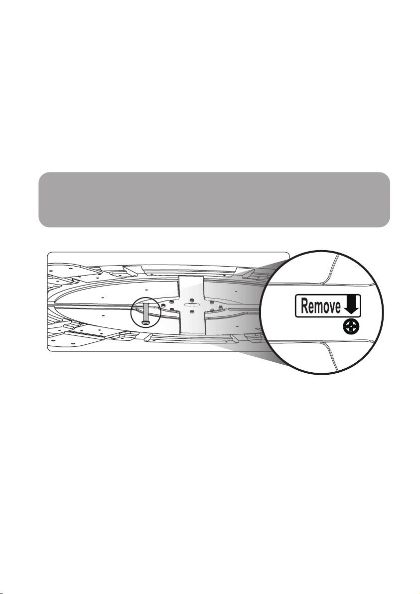
Das Produkt wird mit interner Verriegelung zum Schutz des Gerätes und zur Vermeidung
von Beschädigungen während des Transports geliefert.
Vor der Installation die mit dem "Remove"-Aufkleber gekennzeichnete Verriegelungsschraube in der Unterseite des Gerätes entfernen (siehe nachfolgendes Bild)
Die Antennenabdeckung nicht öffnen, um die Schraube zu entfernen.
Warnung
Es ist darauf zu achten, dass die Verwendung der Antenne vor dem Entfernen des internen
Schloßbolzens die Antenne beschädigen wird, also ist diese Anleitung vor der Installation
sorgfältig zu lesen, um etwaige Schäden am Gerät zu vermeiden.
DEUTSCH- 15
Page 38
7-2 . Erforderlicher Platz für Installation
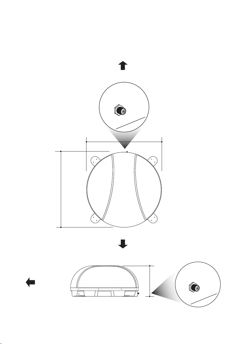
Es ist darauf zu achten, dass es für SNIPE DOME 2 genügend Platz gibt, genauso wie für den
Betriebsbereich.
Rücken des Fahrzeugs
66.0cm
66.0cm
Fahrtrichtung
Fahrtrichtung
31.5cm
DEUTSCH- 16
Page 39
7-3. Ausrüstung für die Installation
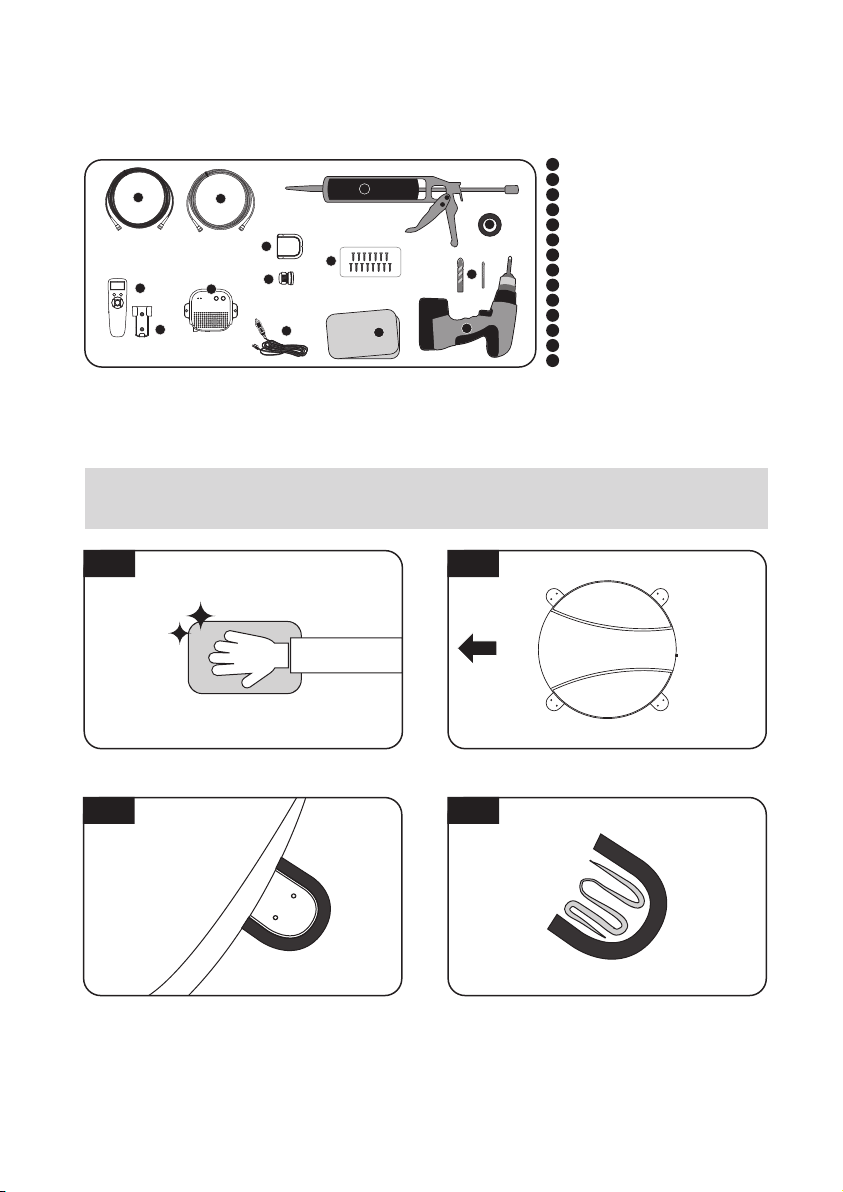
10
5
12
13
11
6
7
9
14
1
2
8
3
4
5
7-4. Instruction for installation
A. SNIPE DOME 2 -Installation auf dem Dach
(Gleiches gilt für alle vier (4) Montageplatten)
1
Silikon
2
Abdeckband
3
Reiniger
4
2mm Bohrer, 20mm Bohrer
5
Bohrmaschine
6
Kabelhalter
7
Kabelverschraubung
8
M4 ×20(15)
9
PI-box
10
PI-kable (1,5m)
11
Signal-kable (10m)
12
Fernbedienung
13
Fernbedienungshalterung
14
Stromversorgungskabel
A-1
Die Oberfläche mit einem Reinigungsmittel
reinigen aufstellen
A-3
Das Abdeckband außerhalb der Montageplatte
befestigen, so dass es 4 mm vom Plattenrand
entfernt ist
A-2
FRONT
Die Antenne in die Mitte des Fahrzeugdachs
A-4
Die Antenne ablegen, um Silikon innerhalb des
geführten Rollmessbands aufzubringen
DEUTSCH- 17
Page 40
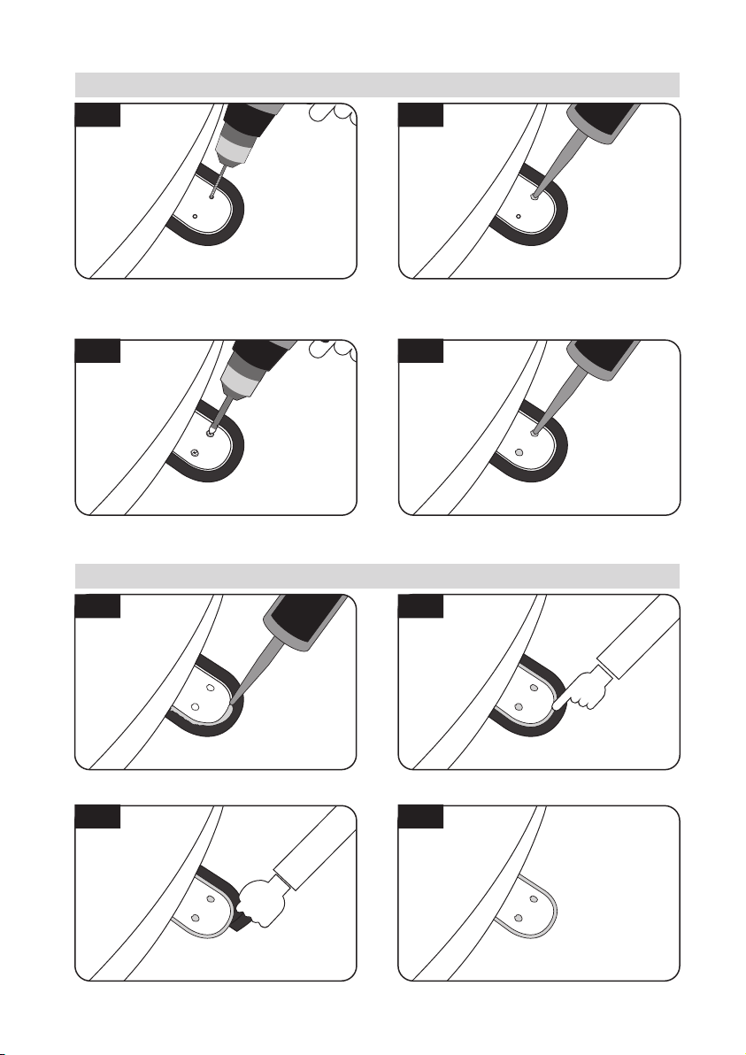
B. Montieren Sie 2 Stück M4x20 Schraube der Montageplatte(4) zu befestigen
B-1
B-2
Das Hauptgerät auf die Oberseite der festen
Platte stellen. Die Montageplatte auf das
aufgetragene Silikon zurückstellen und 2 Löcher
(2 mm) mit Bohrmaschine machen
B-3
7
Die Montageplatte mit 2 Schrauben M4x20
zusammenbauen wieder auftragen
Silikon auf die Löcher auftragen
B-4
8
Silikon auf die angezogenen Schrauben
C. Silikon auftragen zwischen Montageplatte und abdeckband
C-1
Silikon um die Montageplatte auftragen
C-3
C-2
Den Bereich des aufgetragenen Silikons
reinigen
C-4
Das Abdeckband entfernen und es trocknen
lassen
Aufräumen wie auf den Bildern
DEUTSCH- 18
Page 41
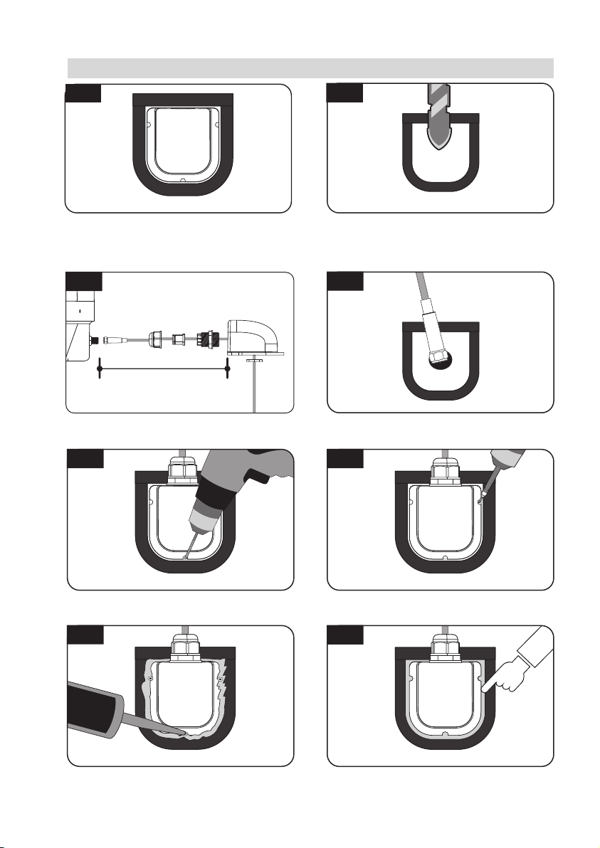
D. Kabelhalter Installation
D-1
Ordnen Sie den Kabelhalter vor der Antennenmitte (30 cm von der Antenne entfernt) an.
Bringen Sie dann das Abdeckband außerhalb
des Kabelhalters an
D-3
approx. 30cm
Richten Sie das Signalkabel, den Kabelhalter und
die Kabelverschraubung wie oben abgebildet ein
D-5
D-2
Bringen Sie 5 mm von der Außenseite des
Halters entfernt Klebeband an und bohren Sie
ein 20-mm-Loch in die Mitte, damit das Kabel
hindurchführen kann
D-4
Stellen Sie sicher, dass die Lochgröße so minimal
ist, sodass ein Kabel durchgezogen werden kann
D-6
Den Kabelhalter in die Klebebandmarkierungen
einsetzen. Drei (3) 2 mm Löcher bohren
Das Silikon um Kabelhalter herum und auf die
Oberseite der Schrauben für Wasserdichtigkeit
aufbringen
DEUTSCH- 19
Den Kabelhalter am Fahrzeugdach mit drei(3)
M4x20 Schrauben an den Bohrlöchern befestigen
D-8D-7
Die Kabel anschließen und das abdeckband
entfernen, danach Silikon vor dem Trocknen
entfernen
Page 42
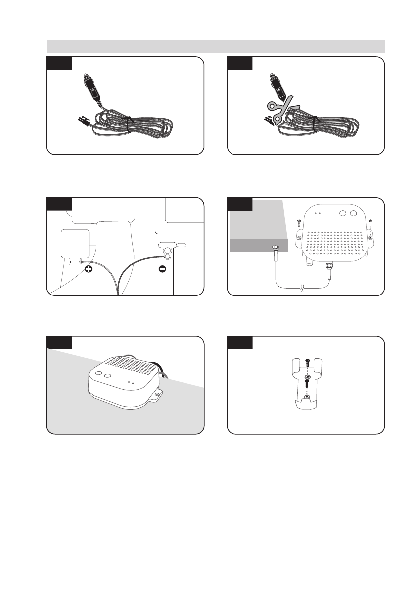
E. PI-box, Fernbedienung und Fernbedienunghalterung Installation
E-1
E-2
Nehmen Sie ein Stromversorgungskabel und
stecken Sie es in Zigarettenanzünder (12V
Steckdose) ein
E-3
12V DC
Stimmen Sie die Polaritäten von Netzkabel den
der Batterie aufeinander ab, rot bis rot / zurück
zu schwarz und weißes Zündkabel zum
Zündanschluss des Fahrzeugs
E-5
Stellen Sie den PI-box auf und schließen Sie die
Kabel an den PI-box (Strom-, Signal- und
PI-kabel) ein
Für die Stromversorgung von der Autobatterie
machen Sie den Zigarrenstecker stromlos, um
innere drei Kabel herauszunehmen und
loskoppeln, um Kupferkabel herauszunehmen
E-4
STB
(Empfänger)
ca. 1,5 m
Befestigen Sie die PI Box dort, wo sie mit zwei
(2) M4x20-Schrauben befestigt werden soll
F-6
Befestigen Sie die Fernbedienungshalterung
dort, wo sie mit zwei (2) M4x20-Schrauben
befestigt werden soll
DEUTSCH- 20
Page 43

Page 44

Contenu
1. Informations générales
1-1. Introduction
1-2. Utilisation et fonctionnement corrects
1-3. Consignes de sécurité
2. Contenu
2-1. L’ensemble des composants
2-2. Nom des pièces
3. Instructions de fonctionnement
3-1. Diagramme de connexion
3-2. Description fonctionnelle
3-3. Référence rapide
...........................................................................................
................................................................................
..........................................................................
......................................................................................
............................................................................
............................................................................
......................................................................................
...............................................................
2
3
3
4
5
6
7
11
4. Mise à jour logicielle
5. Dépannage
.........................................................................................
..........................................................................
6. Caractéristiques
6-1. Dimension
6-2. Spécification
............................................................................................
..........................................................................................
7. Caravan/Motorhome Installation
7-1. Précaution avant l'installation
7-2. Espace requis pour l'installation
7-3. Equipement pour l'installation
7-4. Instruction pour l'installation
........................................................................
................................................................
.......................................................................
.........................................................................
11
12
13
14
15
16
17
17
Page 45
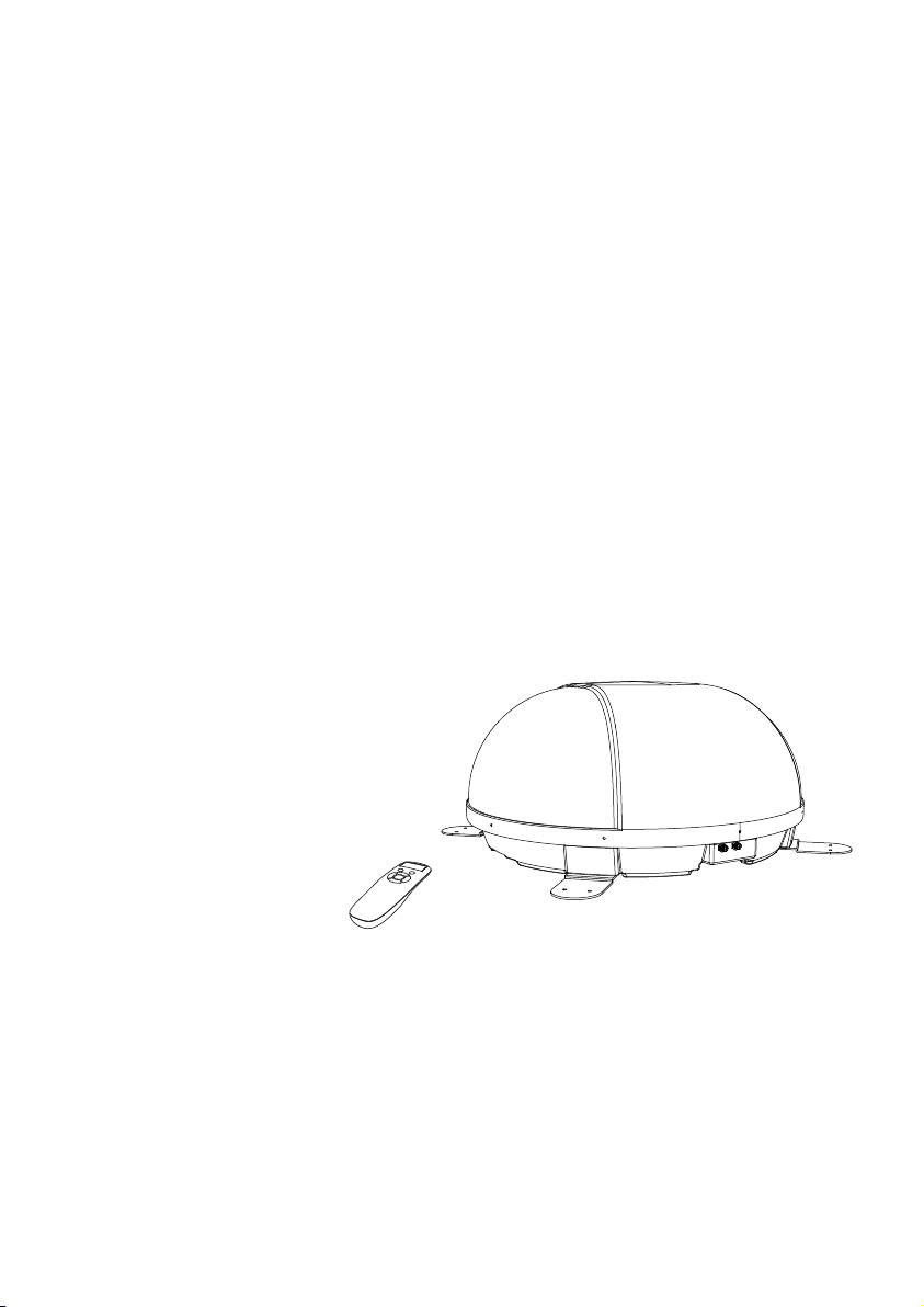
1. Informations générales
1-1. Introduction
Ces instructions décrivent les fonctionnalités et le fonctionnement du système satellite de
SNIPE DOME 2. Un fonctionnement correct et sûr du système ne peut être assuré qu’en
suivant ces instructions.
Votre SNIPE DOME 2 est un système d'antenne de réception TV satellite intelligente qui
peut s'aligner vers un satellite prédéfini automatiquement tant que le système se trouve
dans l'empreinte de ce satellite.
SNIPE DOME 2 n'occupe que l'espace nécessaire alors qu'il effectue les ajustements
nécessaires avec le corps fin et agile de l'antenne.
Pour un fonctionnement général, assurez-vous s'il vous plaît que le système a toujours une
vue dégagée sur le ciel. Si le faisceau de signal du satellite est interrompu par des obstacles
tels que les montagnes, les bâtiments ou arbres, l'appareil ne fonctionnera pas et aucun
signal TV sera reçu.
Les premières pages de ces instructions contiennent des informations sur l'utilisation des
fonctionnalités générales de votre SNIPE DOME 2, suivies par une explication de toutes les
options de réglage. Les dernières pages des instructions couvrent divers aspects
techniques de SNIPE DOME 2.
FRANÇAIS - 2
Page 46

1-2. Utilisation et Fonctionnement corrects
Ce produit a été conçu pour une installation fixe sur des véhicules avec des vitesses
maximales de 130 km / h. Il est conçu pour diriger automatiquement une antenne sur des
satellites de télévision géostationnaires.
L'alimentation du système est fournie par un système électrique de véhicule standard avec
une tension nominale de 12 ou 24 Volts en courant continu.
L'utilisation de l'équipement à d'autres fins que celle spécifiée n'est pas autorisée.
S'il vous plaît, notez également les instructions suivantes du fabricant :
•
Il n'est pas autorisé de changer l'ensemble du dispositif en supprimant ou en ajoutant des
composants individuels.
•
L'utilisation de tout autre composant que ceux initialement installés n'est pas autorisée.
•
L'installation doit être effectuée par un personnel suffisamment qualifié. Toutes les instructions
dans la Notice d’Installation fournie séparément, doivent être suivies attentivement.
•
Le produit ne nécessite aucun entretien régulier. Boîtiers et enveloppes de doivent pas être
ouverts. Les travaux de contrôle et d'entretien doivent toujours être effectués par un spécialiste.
•
Toutes les directives pertinentes et approuvées de l'industrie automobile doivent être
observées et respectées.
L'appareil ne doit être installé sur des toits de véhicule durs.
•
Évitez de nettoyer votre véhicule avec le système satellite monté, dans une station de lavage
•
automatique de voitures ou avec un nettoyeur haute pression.
1-3. Consignes de Sécurité
Veuillez lire attentivement et suivre les instructions de fonctionnement de ce manuel et
utiliser le SNIPE DOME 2 aux fins pour lesquelles il a été conçu.
Lors de l'installation de SNIPE DOME 2, veuillez vous assurer que l'installation est
effectuée avec les câbles fournis et que les câbles ne sont en aucun cas modifiés.
En tant qu'utilisateur de cet équipement, être responsable du respect des lois et
réglementations en vigueur.
Le fabricant décline toute responsabilité pour les dommages consécutifs directs ou
indirects au système, aux véhicules à moteur ou à tout autre équipement en raison d'une
utilisation inadéquate de la batterie ou d'une installation erronée ou d'une mauvaise
connexion des câbles.
FRANÇAIS - 3
Page 47
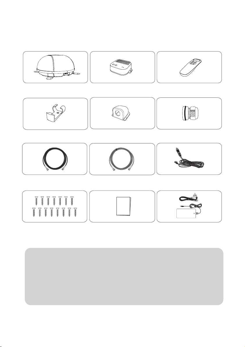
2. Contenu
2-1. L’ensemble des composants
Unité principale Boîtier PI
Support de câbleSupport de télécommande
Câble PI - 1,5m
M4 ×20(15)
Les photos ci-dessus sont pas contractuelles avec les compsants actuels.
※
L’appareil permet d’obtenir de la puissance à partir d’une batterie de voiture.
※
Câble de signal - 10m
(x2 pour les sorties jumelles optionnelles)
Manuel d'utilisation Manuel d'utilisation Adaptateur
Télécommande
Presse-étoupe
Câble d'entrée d'alimentation
(Adaptateur allume-cigare)
(optionel)
Pour élaborer un câble d’entrée d’alimentation pour le branchement direct,
coupez la lumière de la cigarette et détacher pour prendre les câbles en cuivre.
Seul un adaptateur d’alimentation produit par le fabricant de séries SNIPE est
※
garanti et doit être utilisé.
L’adaptateur d’alimentation doit être acheté séparément. Veuillez, s’il vous plait,
※
contacter un revendeur / un magasin local pour plus d’informations.
FRANÇAIS - 4
Page 48
2-2. Nom des pièces
Unité principale
Antenne
au Boîtier PI (port "ANT")
Plaque de montage
Boîtier PI Télécommande
au récepteur (optionnel)
Voyant LED de récepteur
Voyant LED d'alimentation
Bouton HOME
Bouton POWER
Trou de support
de Boîtier PI
Port d'alimentation
Câble de PI vers récepteur
Câble de signal vers l'unite principale
FRANÇAIS - 5
Écran à distance
Bouton BT
Couplage d'antenne
avec télécommande
Bouton Mode
Bouton HOME
Bouton SET
Boutons de flèches
Bouton DiSEqC
Support
de télécommande
Page 49
3. Instructions de fonctionnement
3-1. Diagramme de Connection
Télécommande Application mobile
Boîtier PI
Câble d'entrée d'alimentation
Adaptateur allume-cigare
Câble de signal (10m)
Unité principale
Câble de PI (1,5m)
Récepteur satellite
Tél é
Allumez la puissance Boitier PI après toutes les connexions des câbles
sont complets.
Lorsque vous n'utilisez pas l'antenne, coupez l'alimentation Boitier PI.
FRANÇAIS - 6
Page 50
3-2. Description fonctionnelle
1. Boîtier PI
A. Bouton et LEDs
Câble de signal vers l'unite principale
B. Fonctions de base
i. Mode économie d'énergie
Lors de la réception d'un signal diffusé ou lorsque l'antenne est en position d'HOME, l'antenne ne
a.
fonctionne qu'avec le courant provenant du récepteur
Lors de la recherche d'un satellite ou lorsque l'antenne se déplace, il passe automatiquement à la
b.
puissance connecté à l'adaptateur
Voyant LED de récepteur
Voyant LED d'alimentation
Bouton HOME
Bouton POWER
Trou de support
de Boîtier PI
Port d'alimentation
Câble de PI vers récepteur
i. Bouton d'alimentation
Appuyez sur le Bouton POWER pour
a.
allumer le boîtier PI et alimenter l'antenne.
(LED d'alimentation allumée)
Maintenez la bouton enfoncée pendant
b.
plus de 3 secondes pour éteindre
l'appareil. (LED d'alimentation éteinte)
ii. Bouton HOME
Lorsque le Bouton HOME est enfoncé,
a.
l'antenne se déplace vers la position HOME
iii. Voyant LED de récepteur
Lorsque le récepteur connecté à la Boîtier
a.
PI est sous tension, la Voyant LED de
récepteur s'allume
2. Remote control
Écran à distance
Bouton BT
Couplage d'antenne
avec télécommande
Bouton Mode
Bouton HOME
Bouton SET
Boutons de flèches
Bouton DiSEqC
Support
de télécommande
FRANÇAIS - 7
A. Bouton et Écran
Lorsqu'il n'est pas utilisé pendant plus d'une
i.
minute, il passe en mode d'économie
d'énergie. (Lorsque la batterie est insérée
dans la télécommande)
Pour revenir du mode veille, appuyez sur
ii.
n'importe quel Bouton à l'exception du
Bouton DiSEqC
‘HOME’ ou ‘HOME Position’ se réfère
※
à la position d'attente de l'antenne pour
rechercher des satellites.
Page 51
B. Fonctions de base
CONNECTING
Remote control
Version : 00
SELECT MAC
O - 09 : 39 : E4
PRESS SET
O - 39 : E4
Connected
O - 39 : E4
ASTRA 1
Home
La télécommande recherche automatiquement l'unité d'antenne à
proximité.
S'il y a une antenne qui a été connecté avant, connectez-vous
immédiatement
Lorsque vous utilisez l'antenne et la télécommande pour la première fois
ou lorsque vous supprimez la liste d'antennes stockée dans la télécommande, une liste de produits pouvant être connectés apparaît.
Appuyez sur les boutons gauche et droit de la télécommande pour
sélectionner le code produit de votre antenne, puis appuyez sur le
Bouton SET pour vous connecter à la télécommande
Lorsque la télécommande et l'antenne sont connectées, un message
‘connected’ apparaît
Le code produit de l'antenne connectée, le nom du satellite défini pour
l'antenne et l'état actuel s'affichent.
Appuyez sur le bouton de fléché de gauche ou de droite pour
sélectionner le satellite souhaité et appuyez sur le Bouton SET pour
rechercher le satellite
HOME - Lorsque l'antenne est en position d'HOME
Searching - Lorsque l'antenne recherche des satellites
Found SAT - Lorsque la recherche par satellite est terminée
Mov To Home - l'antenne se déplacera vers la position d'HOME
O - 39 : E4 D
DiSEqC ON
Found SAT
Appuyez sur le Bouton DiSEqC pour modifier les paramètres DiSEqC de
l'antenne.
Le mode DiSEqC est indiqué par la marque [D] sur la première ligne
FRANÇAIS - 8
Page 52
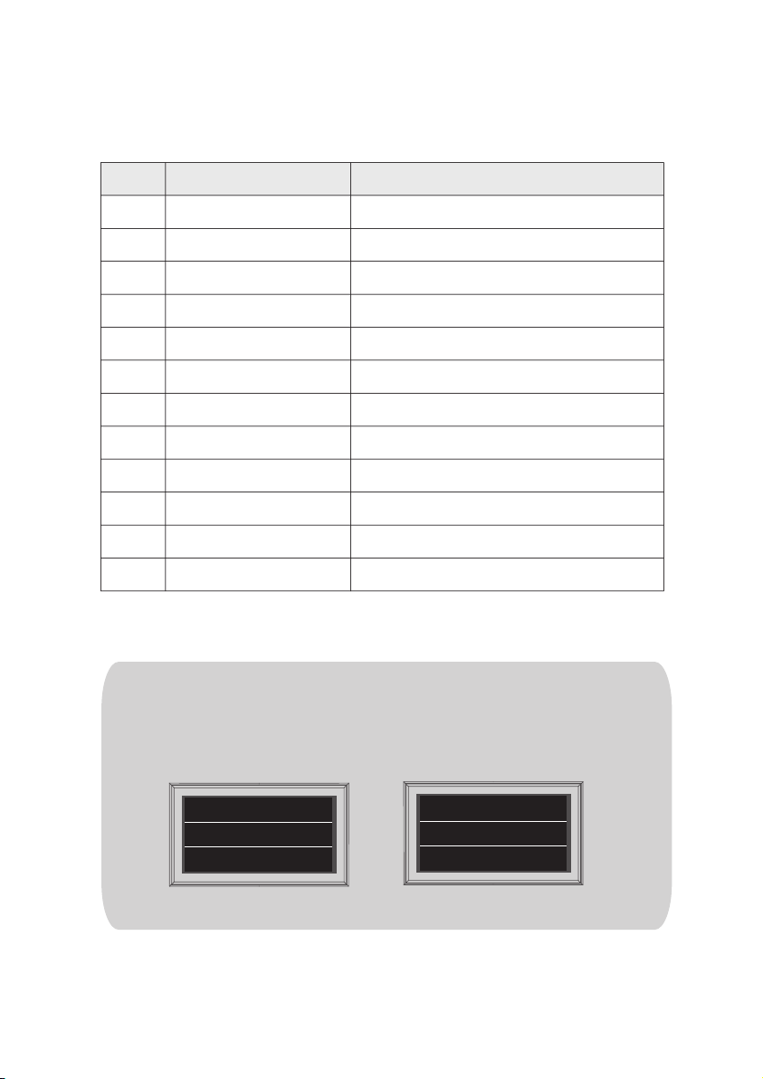
i. Reglage de DiSEqC
Consultez les pré-satellites SNIPE3 pour DiSEqC 1.1 lors de la configuration de l'utilisateur à STB
NO
1
2
3
4
5
6
7
8
9
10
11
12
Pour l'exploitation de DiSEqC, l'utilisateur doit attribuer la liste des satellites DiSEqC a STB est dans
le meme ordre que ci-dessus, la liste preetablie de SNIPE O
La fonction DiSEqC est désactivée lorsque l'antenne est en position HOME.
※
LNB
LNB 1
LNB 2
LNB 3
LNB 4
LNB 5
LNB 6
LNB 7
LNB 8
LNB 9
LNB 10
LNB 11
LNB 12
Satellite
ASTRA1
ASTRA2
ASTRA3
ASTRA1
Hot Bird
Eutelsat 9
ASTRA 4
Thor
Eutelsat 5W
ASTRA1
USER1
USER2
Pour utiliser DiSEqC, appuyez sur le bouton DiSEqC pour activer la fonction
lorsque le message ‘Searching’ ou ‘Found SAT’ apparaît sur l'écran de
la télécommande.
(ex)
Oui Non
O - 39 : E4
ASTRA 1
Searching
FRANÇAIS - 9
O - 39 : E4
ASTRA 1
Home
Page 53
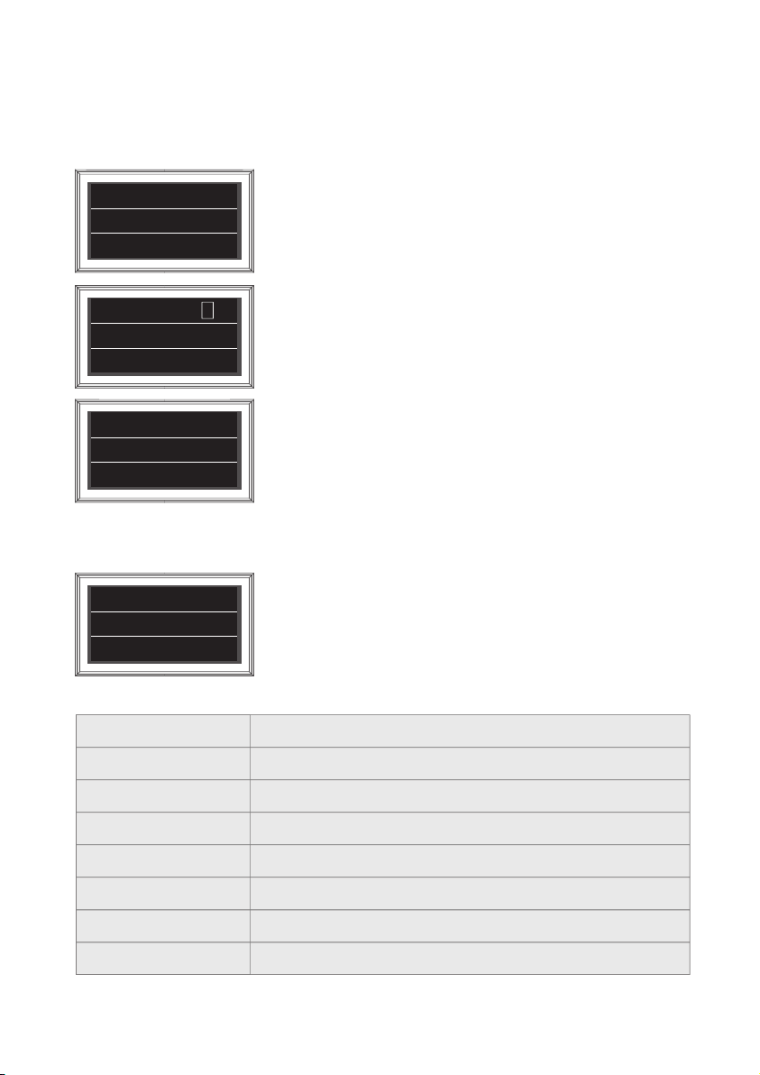
C. Fonction supplémentaire
Bouton BT
i.
Appuyez sur le bouton BT pour passer à l'écran de réglage BT. Appuyez sur la flèche pour accéder
a.
à la fonction souhaitée et réglez avec la bouton SET
BT SET
REMOVE MAC
Supprimez le code produit de l'antenne stockée dans la télécommande.
Utilisé pour se connecter à d'autres produits
PRESS SET
BT SET
REFIND ON
PRESS SET
BT SET
R/C Update
R
La fonction de recherche peut être activée / désactivée.
La fonction de recherche est une fonction qui déplace automatiquement
l'antenne à la position du dernier signal satellite reçu lorsque le récepteur
est allumé.
Lorsque la fonction de recherche est activée, marque [R] dans la première
ligne
Utilisé pour mettre à jour le firmware de la télécommande.
Appuyez sur le Bouton SET pour redémarrer la télécommande en mode
mise à jour
PRESS SET
Appuyez et maintenez enfoncé le Bouton BT pendant plus de 5 secondes pour réinitialiser la
b.
télécommande
D. Message d'erreur
O - 39 : E4 D
ASTRA 1
Si une erreur se produit pendant le fonctionnement, le numéro d'erreur
apparaît avec l'instruction d'erreur
Error 6F
Le message d'erreur est indiqué dans le tableau ci-dessous.
0x00
Non indiqué
0x6A
0x6B
0x6C
0x6E
0x6F
0x70
0x71
Position d'HOME
AZ Mouvement moteur
EL Mouvement moteur
Échec de la vérication du NID
Échec du verrouillage du tuner
Erreur EL LIMIT
Erreur de commutateur de descente EL
FRANÇAIS - 10
Page 54

3-3. Référence rapide
1.
Allumez la télécommande et sélectionnez l'unité qui correspond à l'adresse MAC de votre antenne.
2.
Utilisez les boutons de fléchés gauche et droit pour sélectionner le satellite et appuyez sur
le bouton SET.
3.
Attendez que le message 'FOUND SAT' apparaisse sur l'écran de la télécommande.
4.
Une fois la recherche par satellite terminée, regardez l'émission.
REMARQUE
Afin de vous assurer que votre SNIPE DOME 2 fonctionne correctement, vous devez
vous assurer qu'il est conforme au mode d'emploi de ce manuel et utilisé comme
prévu.
Si le système ne peut pas être complètement retiré en raison de la négligence de
l'utilisateur, il est de votre responsabilité de vérifier que l'antenne est correctement
stockée dans un coffre-fort.
Veuillez également noter que différentes exigences légales sont appliquées au
fonctionnement des équipements électriques et électroniques dans différents pays.
En tant qu'utilisateur de cet équipement, vous êtes responsable de vous assurer du
respect des lois et réglementations en vigueur. Le fabricant décline toute
responsabilité pour les dommages consécutifs directs ou indirects au système, aux
véhicules à moteur ou à d'autres équipements en raison d'une utilisation
inadéquate de la batterie ou d'une installation erronée ou d'une mauvaise
connexion des câbles.
4. Mise à jour programme
4-1. Mise à niveau via l'application
Téléchargez et installez l'application Sat Connect sur l'App Store
a.
Allumez l'antenne (allumez l'alimentation du récepteur et Boîtier PI)
b.
Connecté l'application à l'antenne
c.
Sélectionnez FW UPGRADE dans le menu pour Mise à jour l'antenne
d.
LA MISE À NIVEAU dure environ 5 minutes
e.
FRANÇAIS - 11
Page 55

5. Dépannage
Il y a un certain nombre de problèmes communs qui peuvent affecter la qualité de
réception du signal ou le fonctionnement de la Unit. Les sections suivantes traitent
ces questions et les solutions possibles.
A. Aucune fonction lors de la mise sous tension de l'antenne
i.
Vérifiez à nouveau que toutes les connexions des câbles ont été effectuées correctement.
-
vérifier la connexion entre l'alimentation et le boîtier PI.
-
vérifiez la connexion entre le boîtier PI et l'antenne.
Vérifiez si le câble d'entrée d'alimentation a été endommagé.
ii.
Vérifiez les polarités de la batterie (+/-).
iii.
Vérifiez si la Boîtier PI est sous tension (la DEL d'alimentation de Boîtier PI est allumée).
iv.
B. La télécommande ne s'allume pas
Essayez d'appuyer sur n'importe quel Bouton autre que le Bouton de DiSEqC.
i.
Vérifiez si la batterie est correctement insérée.
ii.
Vérifiez si la pile de la télécommande est épuisée.
iii.
C. Défaut de rechercher le satellite sélectionné
Les signaux des satellites peuvent être bloqués ou dégradés par les bâtiments, les arbres.
i.
Assurez-vous qu'il n'y a aucune obstruction dans la direction vers le sud.
ii.
Sélectionnez un autre satellite à titre d’exemple Astra 3, si elle ce verrous,
puis selectionnez votre satellite, à savoir, Astra1.
Éteignez l'unité et rallumez-la, sélectionnez le satellite de choix.
iii.
D. Problème méchanique
i.
Dans le cas où l'antenne ne tourne pas sur certines positions.
-
Éteignez et rallumez le produit, puis effectuez une nouvelle recherche.
Dans le cas où l'antenne fait un bruit lors du mouvement ou qu'elle a été coincée dans une
ii.
certaine position.
-
Éteignez et rallumez le produit, puis effectuez une nouvelle recherche. s'il ne fonctionne pas,
contacter régional vendeur(ou magasin) pour assistance .
E. Autres
i.
Si le système a été mal câblé, il ne fonctionnera pas correctement. Veuillez contacter régional
vendeur(ou magasin) pour de l'assistance.
FRANÇAIS - 12
Page 56
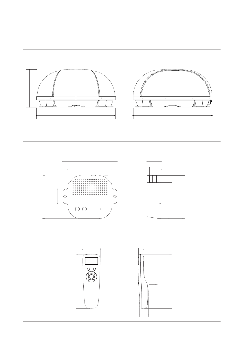
6. Spécications
6-1. Dimension
SNIPE DOME 2
31.5cm
66.0cm 66.0cm
Boîtier PI
102 mm
35 mm
Télécommande
155 mm
129 mm
105 mm
15 mm50 mm
25 mm
34 mm
28 mm
69 mm
85mm
155 mm
102 mm
FRANÇAIS - 13
Page 57

6-2. Spécications
modèle
Fréquence d'entrée
Polarisation
Gain de l'antenne
Dimensions ( W x D x H )
Poids
Min EIRP
Rayon d'angle (élévation / azimut )
Système de commutation par satellite
Temps de recherche du satellite
Sortie
LNB
Energie requise
Consommation d'énergie
Modèle
Fréquence
Prise en charge de la version BT
BLE Gain
Taille (L x P x H)
Taille de l'écran (L X H)
Batterie
Fréquence de sortie
L.O. fréquence
Puissance TX
Sensibilité RX
SNIPE DOME 2
10.7 ~ 12.75 GHz
Horizontale/ Vericale
33.7 dBi @ 12.7 GHz
(ANT) 660 x 660 x 315 mm
(ANT) 9.6 kg / (RCU) 23 g
50 dBW
15° ~ 75° / 390°
DiSEqC
180 secondes (moyenne)
1 / 2 sortie (Optionel)
950 ~ 2,150 MHz
9.75 / 10.6 GHz
DC 12 V
30 W (en mouvement)
SNIPE DOME 2 Télécommande
2.4 GHz
Ver 4.2 / 5.0 (le dernière)
+3 dBm ou plus
-92 dBm ou moins
140 X 50 X 18 mm
128 X 64 Pixels
AAA X 2
FRANÇAIS - 14
Page 58
7. Installation
7. Caravan/Motorhome Installation
7-1. Précaution avant l'installation
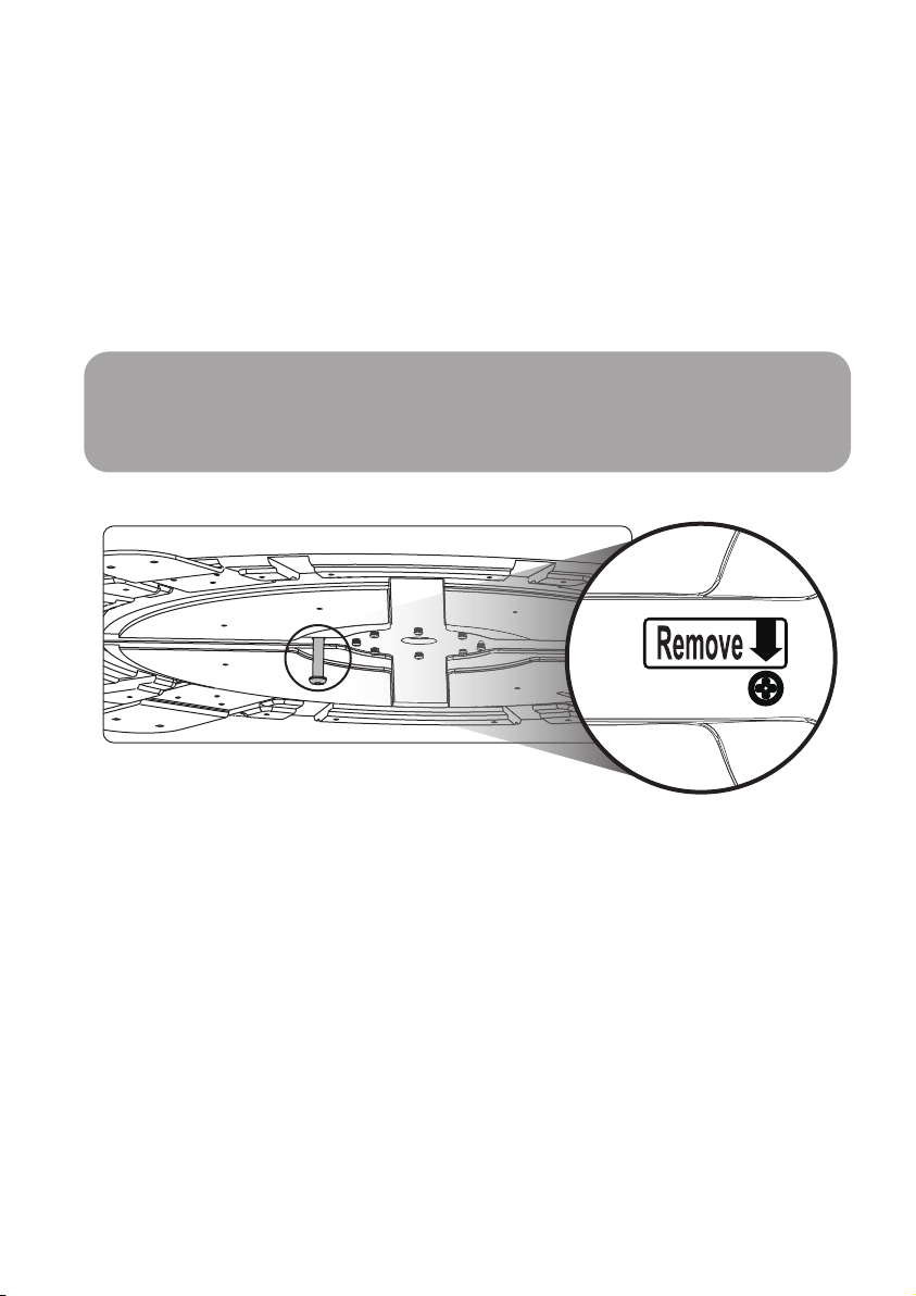
Le produit est livré avec une serrure interne pour protéger l'appareil et prévenir les
dommages pendant le transport.
Avant l’installation, retirez le boulon de verrouillage situé au bas du produit, qui est indiqué
par l’autocollant ‘Remove(Retirez ceci)’ (voir l’image ci-dessous)
N'ouvrez pas le couvercle de l'antenne pour retirer la vis.
Attention
Soyez conscient que l'utilisation de l'antenne avant le retrait du boulon de verrouillage
interne endommagera l'antenne. Assurez-vous donc de lire attentivement ce manuel et les
précautions à suivre avant l'installation pour éviter d'endommager le produit.
FRANÇAIS - 15
Page 59
7-2 . Espace requis pour
Veillez à ce qu'il y ait suffisamment d'espace pour, tout comme pour la plage de fonctionnement.
66.0cm
l'installation
l'arrière du véhicule
66.0cm
Direction de conduite
Direction de conduite
31.5cm
FRANÇAIS - 16
Page 60
7-3. L'équipement pour l'installation
1
Silicone
2
10
5
12
13
11
6
7
9
14
1
2
8
3
4
5
Ruban de masquage
3
Nettoyant
4
Trépan de 2 mm, trépan de 20 mm
5
Perceuse électrique
6
Support de câble
7
Presse-étoupe
8
M4 ×20(15)
9
Boîtier PI
10
Câble PI (1,5m)
11
Câble de signal (10m)
12
Télécommande,
13
Support de télécommande
14
Adaptateur allume-cigarettes
(Cable d'alimentation)
7-4. Instruction pour l'installation
A. Installation Plaque de fixation sur le toit du véhicule
(même pour tous les quatre(4) bords de la plaque de montage)
A-1
Nettoyer la surface avec un nettoyant
A-3
Attacher du ruban de masquage à l'extérieur
de la plaque de montage de 5 mm à partir des
bords de la plaque
A-2
FRONT
Localiser la plaque de montage au centre du
toit du véhicule
A-4
Mettez de côté l'antenne pour appliquer du
silicone à l'intérieur de la ligne de ruban guidée
FRANÇAIS - 17
Page 61
B. 2pcs à vis de boulon M4x20 pour fixer la Plaque de fixation
B-1
B-2
PPlacer la plaque de montage sur la silicone et
faire 2 trous (2 mm) avec une perceuse
électrique
B-3
7
Visser les 2
trous
vis M4x20
Appliquer de la silicone sur les trous
B-4
8
Réappliquer de la silicone pour couvrir les
boulons vissés
C. Appliquer silicone entre la Plaque de fixation et la bande de frottement
C-1
Appliquer silicone autour de Plaque de fixation
C-2
Surface de silicone bien rangé
C-3
Retirer le ruban de masquage et laisser sécher
FRANÇAIS - 18
C-4
Nettoyer comme les images
Page 62
D. Installation du Support de câble
D-1
Disposez le support de câble devant le centre
de l'antenne (à 30 cm de distance) en orientant
le côté ouvert du support de câble. Ensuite,
fixez du ruban adhésif à l'extérieur du support
de câble
D-3
approx. 30cm
Installez le câble de signal, le support de câble et
le presse-étoupe comme sur l'image ci-dessus
D-5
D-2
Appliquez du ruban de masquage à 5 mm de
l'extérieur du support et percez un trou de 20
mm au centre pour permettre au câble de
passer.
D-4
Assurez-vous que la taille du trou est minimale
afin que le câble passe à travers
D-6
Placez et maintenez le support de câble assemblé
à l'intérieur des marquages de bande. Percer trois
(3) trous de 2mm
Appliquer silicone autour de support de câble
et sur le dessus des vis pour l'étanchéité
FRANÇAIS - 19
Fix support de câble sur le toit du véhicule avec
trois (3) des vis M4 x 20 sur les trous de forage
effectués
D-8D-7
Connectez les câbles aux ports relatifs. Retirer le
Bande de frottement alors bien rangé silicone
avant sec
Page 63
E. L'installation du Boîtier PI et de télécommand
E-1
E-2
Obtenez le câble d'alimentation et branchez-le
dans une prise allume cigare (prise 12V)
E-3
12V DC
Raccordez les polarités des câbles d'alimentation aux polarités de la batterie, du rouge au
rouge / arrière au câble d'allumage noir et
blanc au port d'allumage du véhicule
E-5
Placez le Boîtier PI et branchez les câbles PI
(câbles d'alimentation, de signal et de Boîte PI)
Pour alimenter la batterie de la voiture, couper le
connecteur du cigare pour retirer les trois câbles
intérieurs et retirer chacun pour retirer le câble en
cuivre
E-4
STB
approx.1.5m
FIxer Boîtier PI à l'aide des deux vis (M4x16) au
endroit voulu
E-6
FIxer le Support de télécommande à l'aide des
deux vis (M4x16) au endroit voulu
FRANÇAIS - 20
Page 64
I DO IT CO., LTD.
#637, Smart-Hub Industry-University Convergence Center, 237 Sangidaehak-ro,
Siheung-si, Gyeonggi-do, Korea (15073)
TEL +82 (0)31 8041 1500 FAX +82 (0)31 8041 1550
E-MAIL [email protected] WEB www.selfsat.com
 Loading...