

Page 1
ECOS-D Digital Simulcast Technology
Radio Base Station Guide
Installation, configuration and maintenance
Page 2
REVISION TABLE
Date Revision Comment
14/04/2011 4 Environmental condition update
06/04/2011 3 Channel Spacing amendment
31/03/2011 2 Typos amendment
18/03/2011 1 First issue
Information contained in this document may not be used, applied or reproduced for any purpose
unless agreed by SELEX Communications S.p.A. in writing. SELEX Communications S.p.A. reserves
the right to alter without notice the specification, design or conditions of supply of any product or
service.
SELEX Communications logo is a trademark of SELEX Communications S.p.A.
Printed in Italy.
© SELEX Communications S.p.A. All Rights reserved.
SELEX Communications
July 2010
Information contained in this document may not be used, applied or reproduced for any purpose unless agreed
by SELEX Communications S.p.A. in writing
2
Page 3

Summary
1.
Scope ............................................................................................................................................................... 5
2. First aid for electrical shock and safety rules................................................................................................ 5
2.1 First aid for electrical shock ................................................................................................................. 5
2.1.1 Artificial respiration ........................................................................................................................5
2.1.2 Treatment of burns...........................................................................................................................5
2.2 Product Safety and RF Exposure Compliance.................................................................................... 7
2.2.1 RF Exposure Compliance................................................................................................................7
2.2.2 Electrostatic protection .................................................................................................................... 7
3. Technical/Environmental Specification ........................................................................................................ 8
4. ECOS-D DMR4000 – encoding criteria ......................................................................................................10
4.1 RGW4000/RBS4000 ............................................................................................................................ 10
5. Device Assembly and composition ...............................................................................................................12
5.1 Connector positions............................................................................................................................. 14
6. Installation.................................................................................................................................................... 15
6.1 Overview............................................................................................................................................... 15
6.1.1 Installation Pre-requisites .............................................................................................................. 15
6.1.2 Unpack........................................................................................................................................... 16
6.1.3 Mechanical installation.................................................................................................................. 16
6.1.4 Electrical wiring ............................................................................................................................17
6.1.5 Unit grounding............................................................................................................................... 17
6.2 Power Supplies interfaces ................................................................................................................... 19
6.2.1 48 Vdc input .................................................................................................................................. 19
6.3 Radio Interfaces................................................................................................................................... 21
6.3.1 TX N type connector .....................................................................................................................21
6.3.2 RX N type connector ..................................................................................................................... 22
6.4 Line interfaces...................................................................................................................................... 23
6.4.1 4W and 4W+E/M Link.................................................................................................................. 23
6.4.2 AF in/out........................................................................................................................................ 30
SELEX Communications
July 2010
Information contained in this document may not be used, applied or reproduced for any purpose unless agreed
by SELEX Communications S.p.A. in writing
3
Page 4

6.5 Syncronization Interfaces ................................................................................................................... 34
6.5.1 Main GPS Interface ....................................................................................................................... 34
6.6 Other Interfaces................................................................................................................................... 35
6.6.1 Door break-in................................................................................................................................. 35
6.6.2 LAN Interface................................................................................................................................ 36
6.6.3 Serial Interface............................................................................................................................... 38
6.6.4 Auxiliary Serial Interface ..............................................................................................................40
6.6.5 Digital Input/Output Interface .......................................................................................................43
6.6.6 Local Microphone Interface ..........................................................................................................45
7. Configuration ...............................................................................................................................................47
8. Maintenance ................................................................................................................................................. 47
8.1 Module features, alarms and troubleshooting ..................................................................................47
8.1.1 CORE module ...............................................................................................................................47
8.1.2 4 Lines Interface module – LIF ..................................................................................................... 51
8.1.3 SWITCH module........................................................................................................................... 52
8.1.4 DC/DC module.............................................................................................................................. 53
8.1.5 Radio Receiver and Transmitter module - RTX............................................................................ 53
8.1.6 Power Amplifier module - PA....................................................................................................... 55
8.2 Power modules maintenance precaution........................................................................................... 57
8.3 Module removal................................................................................................................................... 58
8.4 Back card removal............................................................................................................................... 59
8.5 Local Maintenance Interface.............................................................................................................. 60
8.6 Local Test AF Interface ......................................................................................................................62
8.7 Remote Maintenance Interface ..........................................................................................................63
SELEX Communications
July 2010
Information contained in this document may not be used, applied or reproduced for any purpose unless agreed
by SELEX Communications S.p.A. in writing
4
Page 5
1. Scope
This manual provides experienced technicians familiar with similar types of equipment with information
which permit the installation and maintenance of the described product, whose characteristics are
described in the Technical specification Section.
This document does not contain information of the maintenance and configuration software that are
provided with the software itself.
Information contained in this document are valid only for the described ECOSD RBS4000I
U2110WA0C14W6E100S1V1G2 (FCCID: X5YF967DHDE-IP) of the ECOS-D DMR4000 Family of
products, optional cards and ancillaries included. The technicians must use only the part of information
related to the RBS really shipped.
2. First aid for electrical shock and safety rules
2.1 First aid for electrical shock
Do not touch the patient with bare hands until the circuit has been opened. pen the circuit by switching
off the line switches. If that is not possible protect yourself with dry material and free the patient from
the conductor.
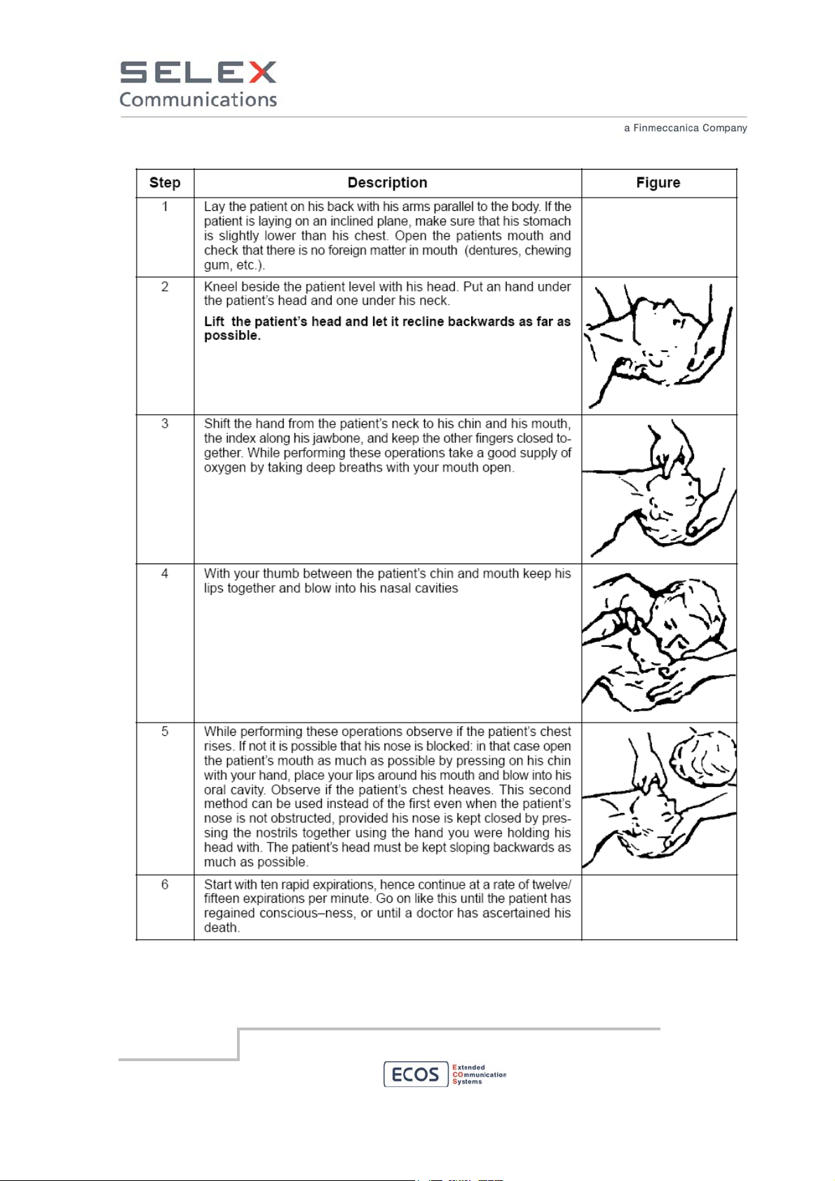
2.1.1 Artificial respiration
It is important to start mouth resuscitation at once and to call a doctor immediately. Suggested
procedure for mouth to mouth resuscitation method is described in Table 1.
2.1.2 Treatment of burns
This treatment should be used after the patient has regained consciousness. It can also be employed
while artificial respiration is being applied (in this case there should be at least two persons present).
Warning
• Do not attempt to remove clothing from burnt sections
• Apply dry gauze on the burns
• Do not apply ointments or other oily substances.
SELEX Communications
July 2010
Information contained in this document may not be used, applied or reproduced for any purpose unless agreed
by SELEX Communications S.p.A. in writing
5
Page 6
SELEX Communications
July 2010
Table 1 First aid
Information contained in this document may not be used, applied or reproduced for any purpose unless agreed
by SELEX Communications S.p.A. in writing
6
Page 7
2.2 Product Safety and RF Exposure Compliance
2.2.1 RF Exposure Compliance
The described product is intended for use in occupational/controlled conditions, where users have full
knowledge of their exposure and can exercise control over their exposure to meet FCC limits. This
RBS is NOT authorized for any other use.
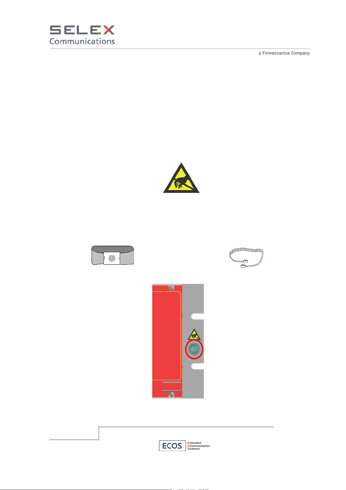
2.2.2 Electrostatic protection
When the equipment units are provided with the plate, shown in Figure 1 it means that they contain
components electrostatic charge sensitive.
Figure 1 Electrostatic sensitive equipment
In order to prevent the units from being damaged while handling, it is advisable to wear an elasticised
band (Figure 2) around the wrist ground connected through coiled cord (Figure 3) to the appropriate
point on the RBS (Figure 4)
Figure 2 Antistatic band
Figure 3 Coiled Cord
Antistatic
contact point
SELEX Communications
July 2010
Figure 4 Antistatic contact point
Information contained in this document may not be used, applied or reproduced for any purpose unless agreed
by SELEX Communications S.p.A. in writing
7
Page 8

3. Technical/Environmental Specification
The main characteristic of the device are:
Radio Frequency:
Frequency range 450 – 526 MHz
Channel Spacing 12,5 kHz
Channel step 5 kHz – 6,25 kHz
RF Power 10 – 110 Watt (step 0,1 dB)
Modulation type Dual mode
Analog FM/PM (EN 300 086 – EN 300 113)
CTCSS 67 – 254.1 Hz (step 0,1 Hz)
DCS yes
Antenna connector 50 Ohm
Emission mode Duplex/Simplex
Receiver sensitivity Analog FM (12,5 kHz): ≤ -112 dBm @ 20 dB SINAD psofo
Digital 4FSK: ≤ -118 dBm @ BER = 5x10
Digital C4FM: ≤ -118 dBm @ BER = 5x10
Power supply:
Input voltage 48 Vdc (35 ÷ 75 Vdc - galvanically insulated)
Current drain
11K0F3E/11K0G3E
Digital 4FSK (TS 102 361-1,2,3)
7K60FXD/7K60FXE
C4FM
8K10F1D/8K10F1E
-2
-2
Stand-by 0,9 A max @ 48 Vdc
Transmit 7 A max @ 48 Vdc
NOTE: current drain values are for fully equipped devices.
Environmental condition:
Operating temperature -30 - +60 °C (-22 - +140 °F)
SELEX Communications
July 2010
Information contained in this document may not be used, applied or reproduced for any purpose unless agreed
by SELEX Communications S.p.A. in writing
8
Page 9

This is the temperature measured in close proximity to the
device. If the device is mounted in a cabinet, the temperature
within the cabinet is measured.
Humidity should not exceed 90% relative humidity @ 50°C (122°F) non
condensating
Air Quality For equipment operating in an environmentally controlled
environment with repeater(s) rack mounted, the airborne
particle level must not exceed 25 µg/m³.
For equipment operating in an area which is not
environmentally controlled (repeater(s) cabinet mounted), air
borne particle level must not exceed 90 µg/m³.
Equipment Ventilation the repeater is equipped with two cooling fans that are used to
provide forced convection cooling. Customer-supplied
cabinets must be equipped with ventilation slots or openings
in the front (for air entry) and back or side panels (for air to
exit). If several repeaters are installed in a single cabinet, be
sure ventilation openings surround each repeater to allow for
adequate cooling. A minimum of ½ RU (4,4 cm – 0,8 inches)
must be left among devices installed in the same cabinet.
SELEX Communications
July 2010
Information contained in this document may not be used, applied or reproduced for any purpose unless agreed
by SELEX Communications S.p.A. in writing
9
Page 10
4. ECOS-D DMR4000 – encoding criteria
The ECOS-D DMR4000 family includes several products.
This section describes the encoding criteria for models of the families
- RGW4000
- RBS4000
4.1 RGW4000/RBS4000
Tab. 4.1: Product Options for the family Rxx4000
General Code: ECOSD Rxx4000y aabbbWAcde4WgE1hmSnVpGr
Type of equipment
Type of backplane
Frequency Band
RF Power
Power Supply
Rxx
xx = GW
- equipment Dual CORE
xx = BS - equipment Single CORE
4000y
- backplane Type A
y = A
y = B - backplane Type B
y = C - backplane Type C
y = G - backplane Type G (dual-core)
y = H - backplane Type H for 25W VHF/UHF and 110W VHF
y = I - backplane Type I for 110W UHF (also valid for 110W VHF)
aa
aa = V1 (66 - 88 MHz)
aa = V2 (145 - 174 MHz)
aa = V3 (136 - 174 MHz)
aa = U1 (400 - 470 MHz)
aa = U2 (450 - 526 MHz)
aa = U3 (854 - 921 MHz)
aa = 00 - indicates no part radio
bbbW
bbb = 025 - Pout 25W
bbb = 110 - Pout 110W
bbb = 000 -
indicates no Power Amplifier module
Acde
A - indicates 12Vdc power supply
c = 0 c = 1 d = 0 -
does not provide 12Vdc power supply
provides 12Vdc power supply
indicates the absence of alternatives at 12Vdc powr supply
d = B - indicates 24Vdc power supply
SELEX Communications
July 2010
Information contained in this document may not be used, applied or reproduced for any purpose unless agreed
by SELEX Communications S.p.A. in writing
10
Page 11
d = C - indicates 48Vdc power supply
d = D - indicates 72Vdc power supply
d = E - indicates 230Vac power supply
e = 1 - indicates one power supply module
e = 2 - indicates two power supply modules
e = 3 - indicates three power supply modules
…
e = 0 - indicates no power supply modules
4 Wires interfaces
4Wg
g = 1 - indicates one LIF (Line Interface module) with back-
card
g = 2 - indicates two LIF (Line Interface modules) with back-
card
…
g = 0 indicates no Line Interface modules and no back-card
E1 Interfaces
E1hm
h = C - indicates back-DIF (Digital Interface back-card) with
coax connectors @75 Ohm unbalanced
h = R - indicates back-DIF (Digital Interface back-card) with
RJ45 connectors @120 Ohm balanced
h = 0 - indicates no back-DIF
m = 1 - indicates one Digital Interface module
m = 2 - indicates two Digital Interface modules
…
m = 0 - indicates no Digital Interface modules
Option Board SOIP
Sn
n = 1
- indicates one SOIP piggy-back on one CORE module
n = 2 - indicates two SOIP piggy-back on two CORE modules
n = 0 - indicates no SOIP piggy-back
Option Board VOCODER
Vp
p = 1
- indicates one VOCODER piggy-back on one CORE
module
p = 2 - indicates two VOCODER piggy-back on two CORE
modules
p = 0 - indicates no VOCODER piggy-back
Synchronization GPS receiver
Gr
r = 1
- indicates one GPS receiver piggy-back on one CORE
module (Master)
r = 2 - indicates two GPS receiver piggy-back on one CORE
module (Master)
r = 0 - indicates no GPS receivers piggy-back
SELEX Communications
July 2010
Information contained in this document may not be used, applied or reproduced for any purpose unless agreed
by SELEX Communications S.p.A. in writing
11
Page 12

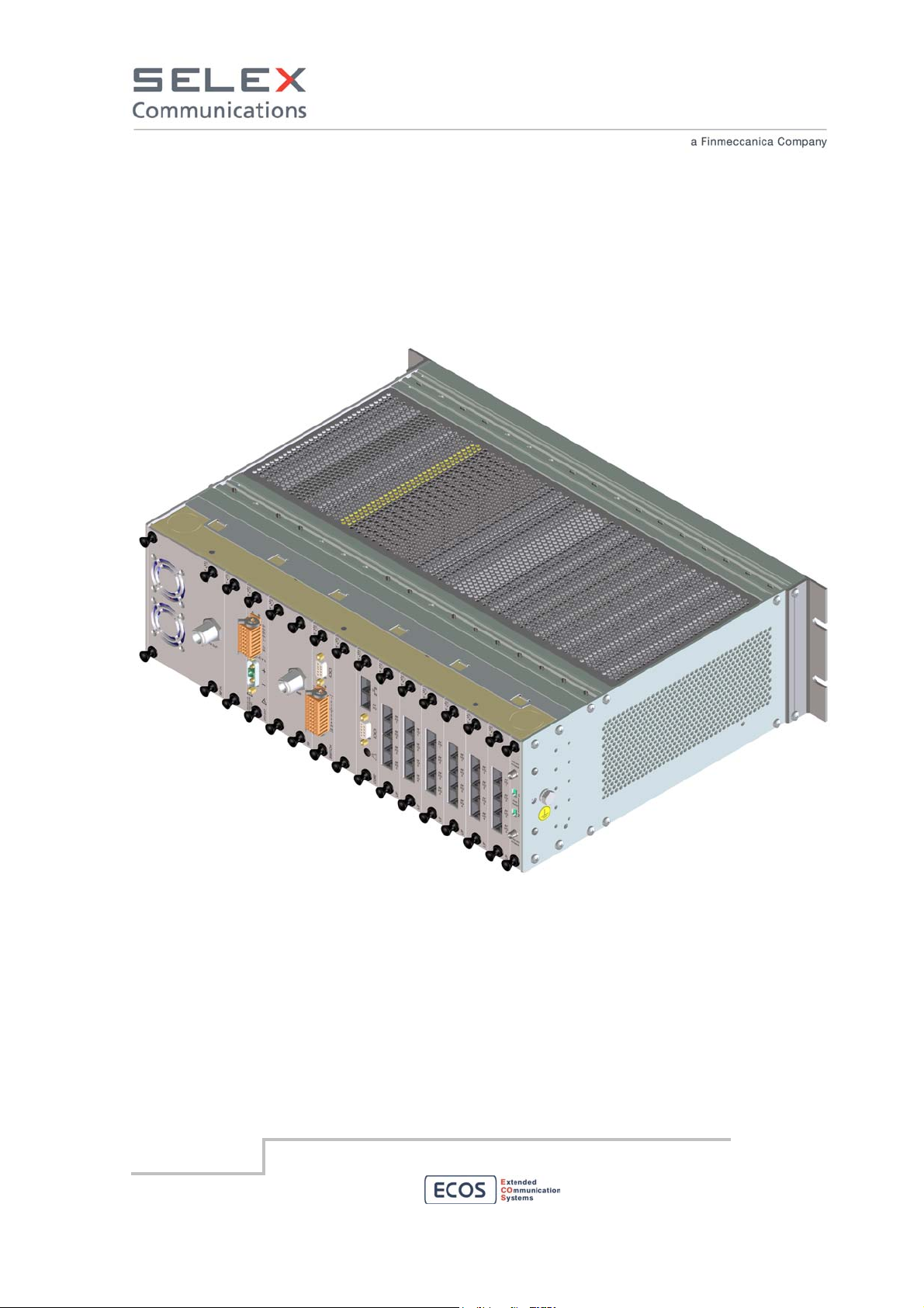
5. Device Assembly and composition
SELEX Communications
July 2010
Information contained in this document may not be used, applied or reproduced for any purpose unless agreed
by SELEX Communications S.p.A. in writing
12
Page 13
SELEX Communications
July 2010
Information contained in this document may not be used, applied or reproduced for any purpose unless agreed
by SELEX Communications S.p.A. in writing
13
Page 14
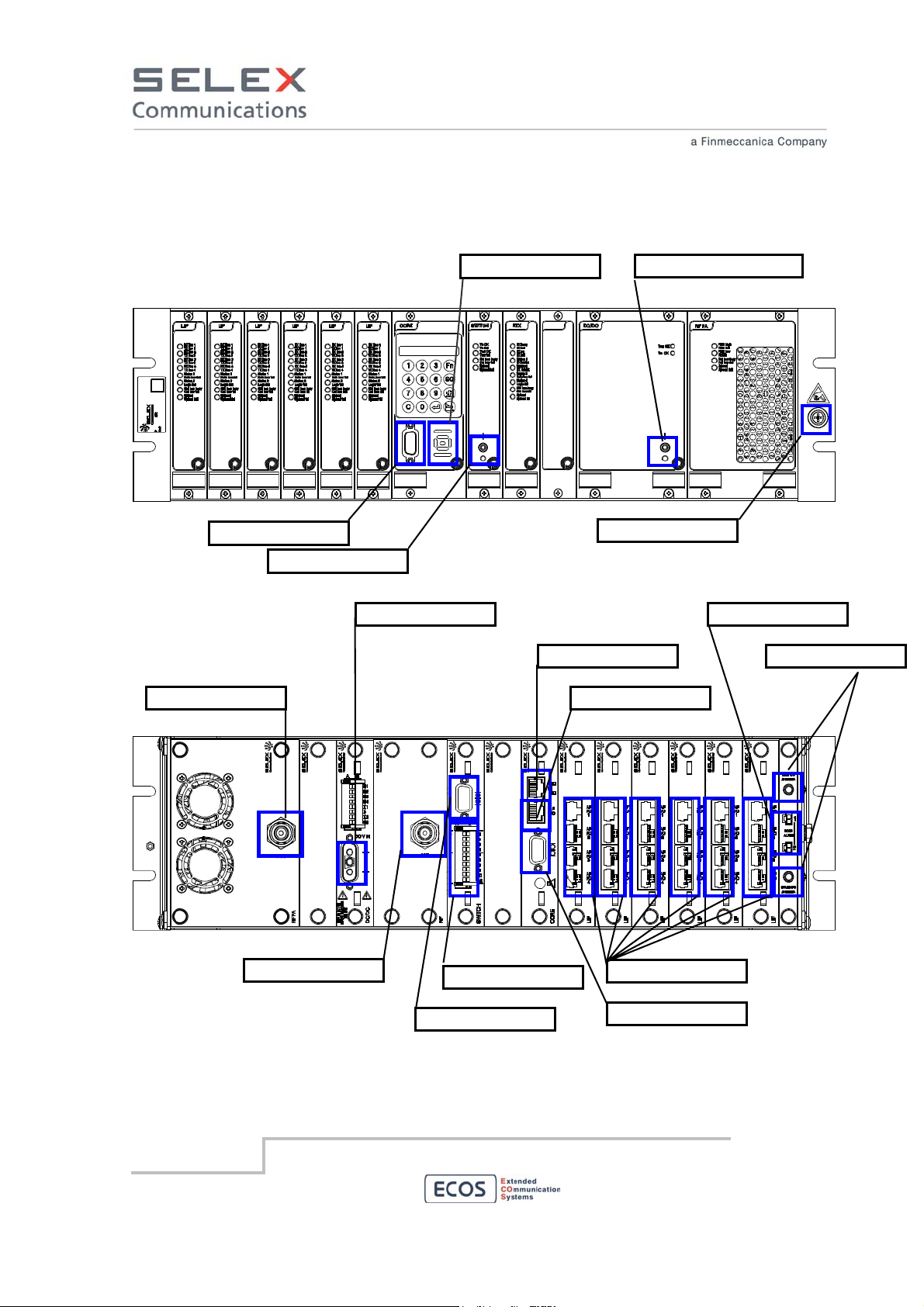
5.1 Connector positions
Microphone/AF test
RF TX antenna
Power on/off switch
48 VDC input
Loudspeaker
Main Power on/off switch
Antistatic contact
LAN port
4W(+E/M) local port
Door Alarm
GPS antenna
SELEX Communications
July 2010
RF RX antenna
AUX Serial port
Information contained in this document may not be used, applied or reproduced for any purpose unless agreed
by SELEX Communications S.p.A. in writing
I/O port
4x4W(+E/M) link ports
Main Serial port
14
Page 15

6. Installation
6.1 Overview
The device can be shipped preinstalled in a cabinet or not. If it is not shipped preinstalled in a cabinet,
after unpacking, mechanical installation takes place, followed by electrical connections as described in
this document. The device may be installed in any location suitable for electronic communications
equipment, provided that the environmental conditions do not exceed the equipment specifications for
temperature, humidity, and air quality and that the access to that location is restricted as described
below:
• access can only be gained by service persons or by users who have been instructed about the
reasons for the restrictions applied to the location and about any precautions that be taken;
and
• access is through the use of a tool or lock and key, or other means of security, and is
controlled by the authority responsible for the location
6.1.1 Installation Pre-requisites
To ensures the best possible performance and reliability of the described equipment pre-installation
planning is required. This includes considering the mounting location of the repeater in relation to input
power and antennas. Also to be considered are site environment conditions, the particular mounting
method and required tools and equipment.
To plan the installation, please pay particular attention to environmental condition at the site,
ventilation requirements, and grounding and lightning protection as described in this manual.
After that, following the instruction given in this manual:
• Unpack and inspect the equipment.
• Mechanical install the equipment at the site.
• Make necessary electrical wiring:
- Unit Grounding
- DC input cabling
- Coaxial cables to transmit and receive antennas
• Perform a post-installation function checkout test of the equipment to verify proper installation.
• Proceed to customize the repeater parameters per customer specifications (e.g. operating
frequency, PL, codes, color code, etc.)
SELEX Communications
July 2010
Information contained in this document may not be used, applied or reproduced for any purpose unless agreed
by SELEX Communications S.p.A. in writing
15
Page 16
6.1.2 Unpack
Inspect the equipment for damage immediately after unpacking and make a report of the extent of any
damage to the transportation company and to SELEX Communications S.p.A.
The following items are packed together:
• ECOS-D A2T Radio Base Station
• DC power cable
• This manual
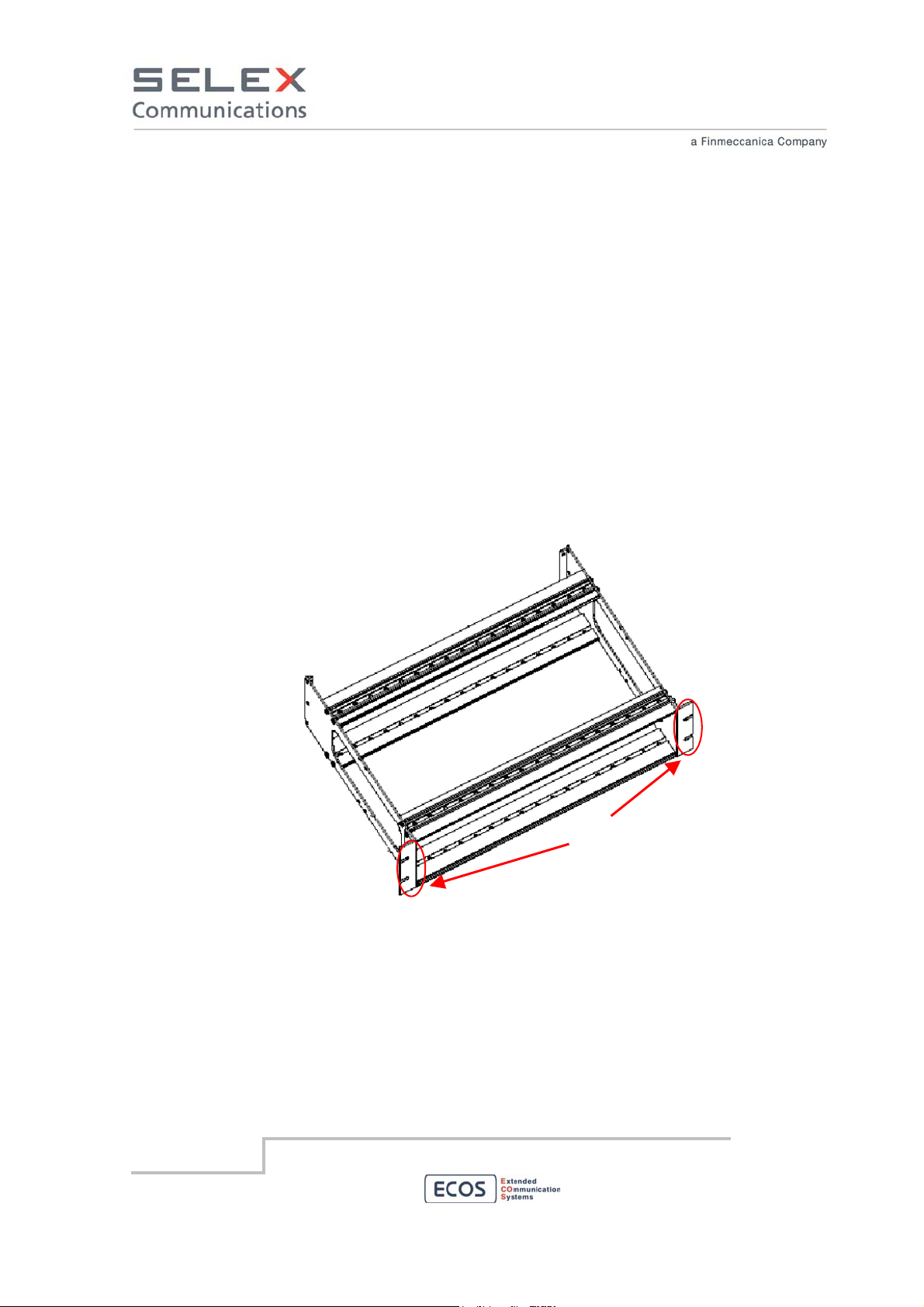
6.1.3 Mechanical installation
The device is shipped in a box. Upon delivery, the equipment must be removed from the container
(see Unpack section) and transferred to a rack or cabinet. Refer to this manual for all the installation
requirements.
The device is designed to be fitted in a 19” cabinet using 3 RU of space.
M6 screws
Customer-supplied cabinets and racks must have mounting rail and hole spacing compatible with EIA
Universal 48.3 cm (19 inches) specifications. Cabinets must provide adequate ventilation and must
meet the following criteria:
• 45.0 cm (17.71 inches) deep
• 48.3 cm (19 inches) wide
• 13.4 cm (5.25 inches) high
SELEX Communications
July 2010
Information contained in this document may not be used, applied or reproduced for any purpose unless agreed
by SELEX Communications S.p.A. in writing
16
Page 17
• Two mounting rails 5 cm (2 inches) from front cabinet with front mounting holes 5.7 cm (2.25
inches) apart (center to center).
The front of the device is provided with four holes for M6 screws. This permits to fasten the device to a
19” rack by means of 4 M6 screws.
If several devices are installed in a single cabinet, be sure equipment have to be spaced at least by
1/2 RU (2,2 cm, 0,8 inches).to allow for adequate cooling.
Cabinets must have a least 15 cm (6 inches) of open space between the air vents and any wall or
other cabinets. This allows adequate air flow.
When multiple cabinets (each equipped with several repeaters) are installed in an enclosed
area, ensure appropriate ventilation and consider air conditioning or other climate control
equipment to satisfy the temperature requirements.
6.1.4 Electrical wiring
The electrical wiring must be done using appropriate cables thus assuring the equipment responds to
the electromagnetic compatibility standards.
The cable terminates to flying connectors which have to be connected to the corresponding
connectors on the equipment rear panel. The connector of the power cable supplied with the product
is the means to disconnect the device from the power source.
Position and pin–out of the equipment connectors are available in the appropriate section in the
following of this document.
6.1.5 Unit grounding
The device is equipped with a ground nut located on the rear panel of the device and identified by a
label. This nut must be used for a direct connection of the device to the site grounding, even if the
device is included in a cabinet. All antenna cables and DC power cabling should be properly grounded
and lightning protected. Failure to provide proper lightning protection may result in permanent damage
to the radio equipment.
SELEX Communications
July 2010
Information contained in this document may not be used, applied or reproduced for any purpose unless agreed
by SELEX Communications S.p.A. in writing
17
Page 18
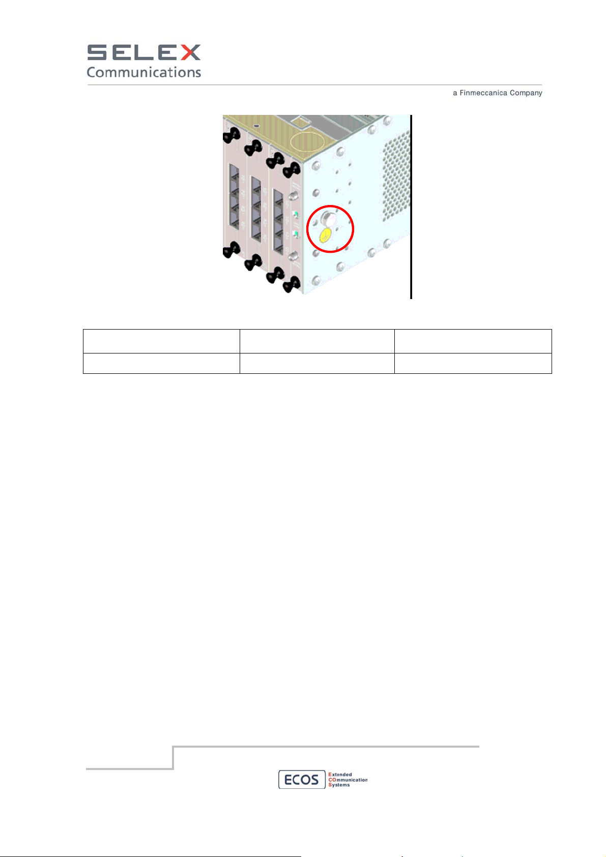
Ground
connector
Figure 5 Ground connector
Interconnecting points Type of connector terminating
Type of cable/conductor
the cable
Ground M6 nut Section area ≥ 6 sq. mm
Note. Resistance between ground terminal and other metallic parts of the device verified applying
between the two sides a current of 32 A for 4 minutes.
SELEX Communications
July 2010
Information contained in this document may not be used, applied or reproduced for any purpose unless agreed
by SELEX Communications S.p.A. in writing
18
Page 19
6.2 Power Supplies interfaces
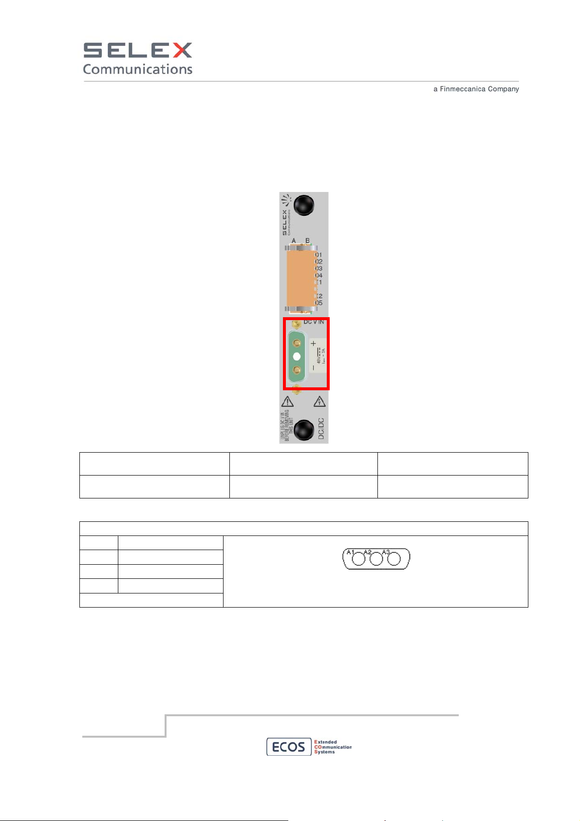
6.2.1 48 Vdc input
Use the connector marked in red to connect RBS to the output of the 48 VDC power supply. Each
level must be connected separately the 48 VDC power supply. The RBS is galvanically insulated..
Interconnecting points Type of connector terminating
Type of cable/conductor
the cable
Power supply 35 – 75 Vdc Polarised SUB–D 3W3 female
connector
Section of each wire ≥ 4 sq.mm.
(for length < 6 m)
D-SUB 3W3 female pinout
PIN
A1 Negative voltage
A2 Not used
A3 Positive voltage
(soldering side view)
Hereafter the power cable supplied with the 48 Vdc powered device is shown. The cable is provided
with D-SUB 3W3 female connector and a 30A fuse.
SELEX Communications
July 2010
Information contained in this document may not be used, applied or reproduced for any purpose unless agreed
by SELEX Communications S.p.A. in writing
19
Page 20
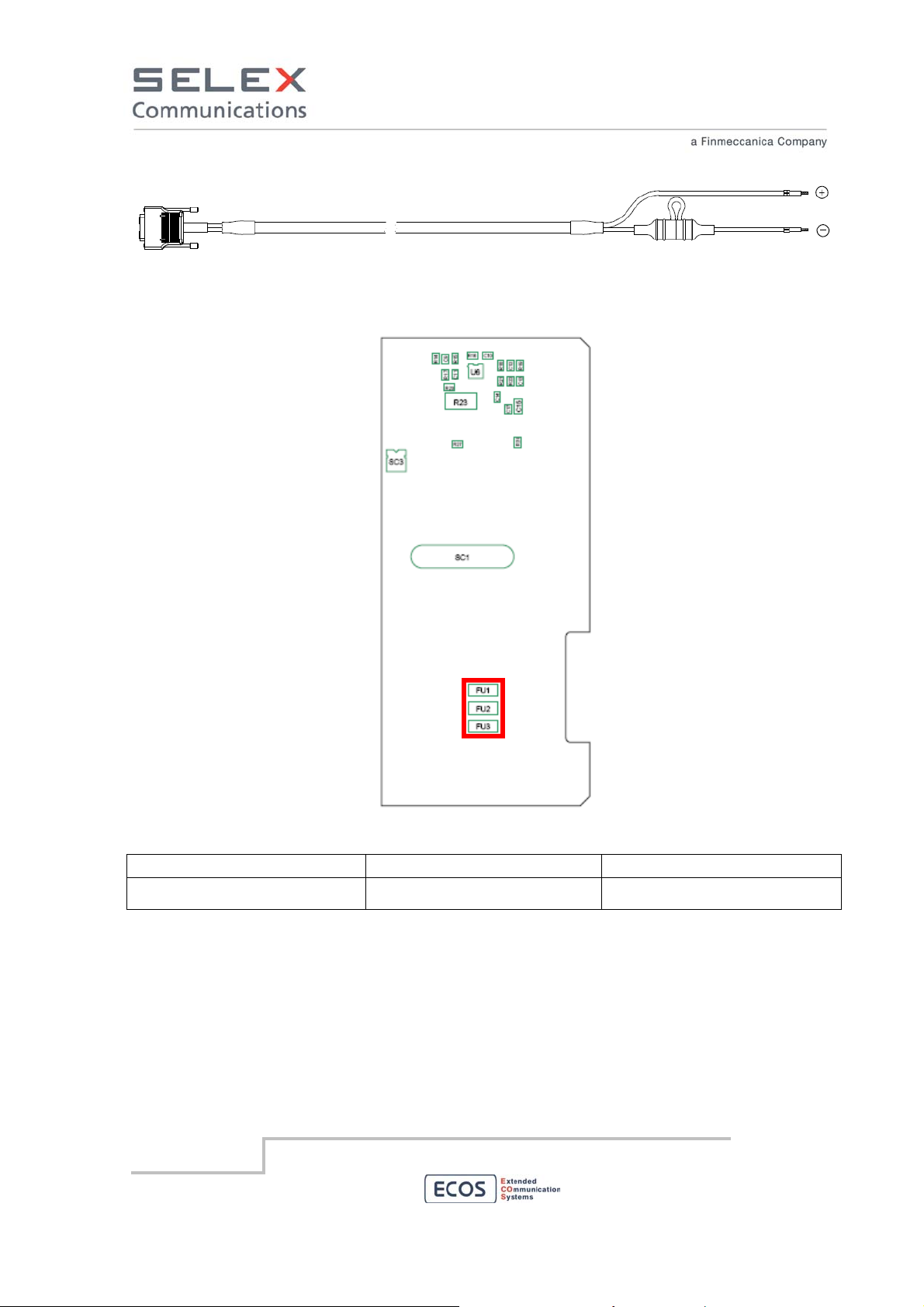
The 48 Vdc Back Card hosts three 10A fuses. Position of FU1, FU2 and FU3 is indicated in the figure
below.
Electrical characteristics of the fuses are described in the table below.
Ampere rating (A) Voltage rating (V) Nominal Melting (I
10 125 26.46
SELEX Communications
July 2010
Information contained in this document may not be used, applied or reproduced for any purpose unless agreed
by SELEX Communications S.p.A. in writing
2 A2
Sec.)
20
Page 21

6.3 Radio Interfaces
6.3.1 TX N type connector
In RBS without branching and using duplex mode of operation connect the transmitter cable to the “TX
OUT” connector as shown in the following figure.
Interconnecting points Type of connector terminating
Type of cable/conductor
the cable
TX Antenna N male connector 50 ohm coaxial cable with
double shield
SELEX Communications
July 2010
Information contained in this document may not be used, applied or reproduced for any purpose unless agreed
by SELEX Communications S.p.A. in writing
21
Page 22

6.3.2 RX N type connector
In RBS without branching and using duplex mode of operation connect the transmitter cable to the
“RX IN” connector as shown in the following figure.
Interconnecting points Type of connector terminating
Type of cable/conductor
the cable
Antenna N male connector 50 ohm coaxial cable with
double shield
SELEX Communications
July 2010
Information contained in this document may not be used, applied or reproduced for any purpose unless agreed
by SELEX Communications S.p.A. in writing
22
Page 23

6.4 Line interfaces
6.4.1 4W and 4W+E/M Link
If the RBS is equipped with a LIF module on the rear panel 4 4W+E/M connectors are present. The
following figure shows the rear panel of the LIF module. Configuration of the feature of this four links is
out of the scope of this manual. The electrical interface is described in this section. Usually these AF
links are used to establish RBS to RBS links or RBS to RNFE links.
+
Interconnecting points Type of connector terminating
Type of cable/conductor
the cable
4W or 4W+E/M Link port RJ45 male connector AWG 24 Category 5
SELEX Communications
July 2010
Information contained in this document may not be used, applied or reproduced for any purpose unless agreed
by SELEX Communications S.p.A. in writing
23
Page 24

PIN
1 Mouth (M+)
2 Mouth (M-)
3 Ear (E+)
4 AF_OUT (-)
5 AF_OUT (+)
6 Ear (E-)
7 AF_IN (-)
8 AF_IN (+)
PIN 4W+E/M 4W
1 M (+) Mouth signal + not connected
2 M (-) Mouth signal - not connected
3 E (+) Ear Signal + not connected
4 AF_OUT (-) 600 Ohm Balanced OUT AF 600 Ohm Balanced OUT AF
5 AF_OUT (+) 600 Ohm Balanced OUT AF 600 Ohm Balanced OUT AF
6 E (-) Ear Signal - not connected
7 AF_IN (-) 600 Ohm Balanced IN AF 600 Ohm Balanced IN AF
8 AF_IN (+) 600 Ohm Balanced IN AF 600 Ohm Balanced IN AF
4W+E/M line RJ45 female pinout
4W+E/M and 4W line usage
E/M pin usage
PIN
Balanced Unbalanced
1 M (+) Mouth signal + Mouth signal
2 M (-) Mouth signal - not connected
3 E (+) Ear Signal + Ear Signal
6 E (-) Ear Signal - not connected
SELEX Communications
July 2010
Information contained in this document may not be used, applied or reproduced for any purpose unless agreed
by SELEX Communications S.p.A. in writing
24
Page 25
4W cabling example: link between RBS A and RBS B
RJ-45, RBS A side RJ-45, RBS B side
M (+) 1 Not connected Not connected 1 M (+)
M (-) 2 Not connected Not connected 2 M (-)
E (+) 3 Not connected Not connected 3 E (+)
AF_OUT (-) 4 White-blue White-orange 4 AF_OUT (-)
AF_OUT (+) 5 Blue Orange 5 AF_OUT (+)
E (-) 6 Not connected Not connected 6 E (-)
AF_IN (-) 7 White-orange White-blue 7 AF_IN (-)
AF_IN (+) 8 Orange
Blue 8 AF_IN (+)
E/M Hardware Line settings
All the E/M signals share a common voltage reference. The four Mouth signals may be hardware
configured independently. The four Ear signals share the same hardware configuration in couple of
lines. For unbalanced settings connect the two communicating entities to the same ground.
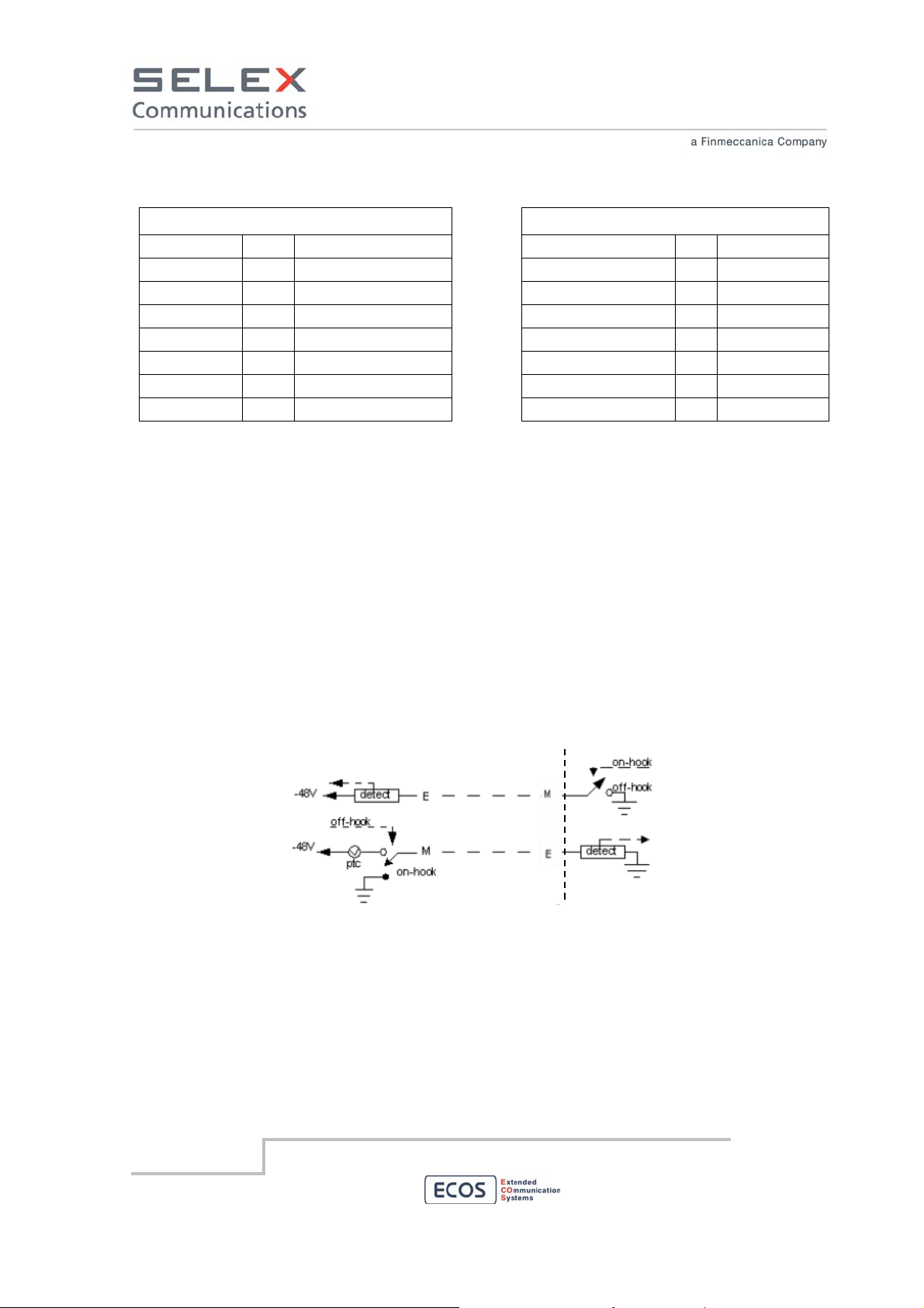
E/M Type I Interface Model
E/M Type I is the original E/M lead signaling arrangement and it is the most common interface type in
North America. The following diagram displays the sent signal states for active/not active signaling.
The RBS grounds its M−lead to signal a seizure. The other device applies battery to its M−lead to
signal a seizure. The RBS expects to see active conditions on the E−lead and signal active to the
remote device on M−lead.
RBS side
E/M Type II Interface Model
E/M Type II provides a four−wire fully−looped arrangement that provides full isolation between the
trunks and signaling units. The following table displays the sent signal states for active/not active
signaling. The RBS grounds its M−lead to signal a seizure. The other device applies battery to its
M−lead to signal a seizure. The RBS expects to see active conditions on the E−lead and signal active
to the remote device on M−lead.
SELEX Communications
July 2010
Information contained in this document may not be used, applied or reproduced for any purpose unless agreed
by SELEX Communications S.p.A. in writing
25
Page 26
M+
M-
E+
E-
RBS side
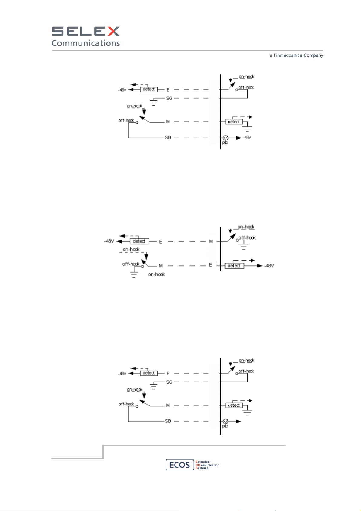
E/M Type V Interface Model
E/M Type V interface is a symmetrical two−wire lead arrangement that signals in both directions by
means of open for not active and ground for active signalling. The following table displays the sent
signal states for active/not active signaling. The RBS grounds its M−lead to signal a seizure. The other
device applies battery to its M−lead to signal a seizure. The RBS expects to see active conditions on
the E−lead and signal active to the remote device on M−lead.
RBS side
E/M Proprietary Type Interface Model
E/M Proprietary Type provides a four−wire fully−looped arrangement that provides full isolation
between the trunks and signaling units. The following table displays the sent signal states for
active/not active signaling. The RBS grounds its M−lead to signal a seizure. The other device applies
battery to its M−lead to signal a seizure. The RBS expects to see active conditions on the E−lead and
signal active to the remote device on M−lead.
M+
M-
E+
SELEX Communications
July 2010
E-
RBS side
Information contained in this document may not be used, applied or reproduced for any purpose unless agreed
by SELEX Communications S.p.A. in writing
+48v
26
Page 27

E/M Hardware settings
Type I
(Unbalanced)
Type II
(Balanced)
Type V
(Unbalanced)
proprietary
(Balanced)
IP3 1 ON OFF OFF ON
2 ON OFF OFF ON
IP5 1 OFF ON ON OFF
2
voltage
reference
OFF ON ON OFF
IP6 1 E line 3&4 ON OFF ON OFF
2 E line 1&2 ON OFF ON OFF
IP7 1 M line 2 ON OFF ON OFF
2 M line 1 ON OFF ON OFF
IP8 1 M line 4 ON OFF ON OFF
2 M line 3 ON OFF ON OFF
IP3
IP5
IP6
IP7
IP8
Back card deep switch positioning
Where, in the equipment described in this document, a 4 wires interface towards a common
communication network is used, it is mandatory to use 4 (four) different copper pairs: two of them are
SELEX Communications
July 2010
Information contained in this document may not be used, applied or reproduced for any purpose unless agreed
by SELEX Communications S.p.A. in writing
27
Page 28
used to transfer from one to the other RBS the user payload and two of them are optionally used to
transfer E and M criteria.
All the signals are exchanged using a balanced type of connection, avoiding any ground reference.
For the two copper pairs used for exchanging the user payload, the impedance of the interface is 600
Ohm.
The characteristics of the pairs must be as follows:
Amplitude:
Amplitude characteristic of the media must comply with FIGURE 2/G.712 (ITU-T Rec.G.712 page 8).
The mask is shown below. Anyway in the audio band from 300 Hz to 3400 Hz the response must be
+/- 1,5 dB with respect to the nominal level of –10 dBm.
dB
1.8
0.9
0.5
Loss
0
–0.5
0 200 300 1020 2400 3000 3400 3600 Hz
NOTE – In some applications in which several PCM channels may be connected in tandem, it may be
necessary to extend the +0.5 dB limit from 2400 Hz to 3000 H z.
Frequen cy (f )
(see Note)
T1511850-02
Group delay:
Group delay characteristic of the media must comply with FIGURE 6/G.712 (ITU-T Rec.G.712 page
10). The mask is shown below.
ms
1.50
0.75
Group delay distortion
Insertion loss:
SELEX Communications
July 2010
0.25
0
Information contained in this document may not be used, applied or reproduced for any purpose unless agreed
500 600 2800
1000 2600 Hz
Frequency (f)
by SELEX Communications S.p.A. in writing
T1511890-02
28
Page 29

The insertion loss must be 0dB +/- 3 dB. This must be true also with regard to the aging of the media
physically used.
Noise:
The characteristic of the media must comply with prescriptions contained in chapter 9 (noise) of book
III.4-Rec.G.792 page 4 and following.
Diaphony:
The pairs of the media used to transport the user payload must have a diaphony attenuation greater
than 40 dB.
E/M time response:
The response time of E/M criteria must be less than 100 msec.
SELEX Communications
July 2010
Information contained in this document may not be used, applied or reproduced for any purpose unless agreed
by SELEX Communications S.p.A. in writing
29
Page 30
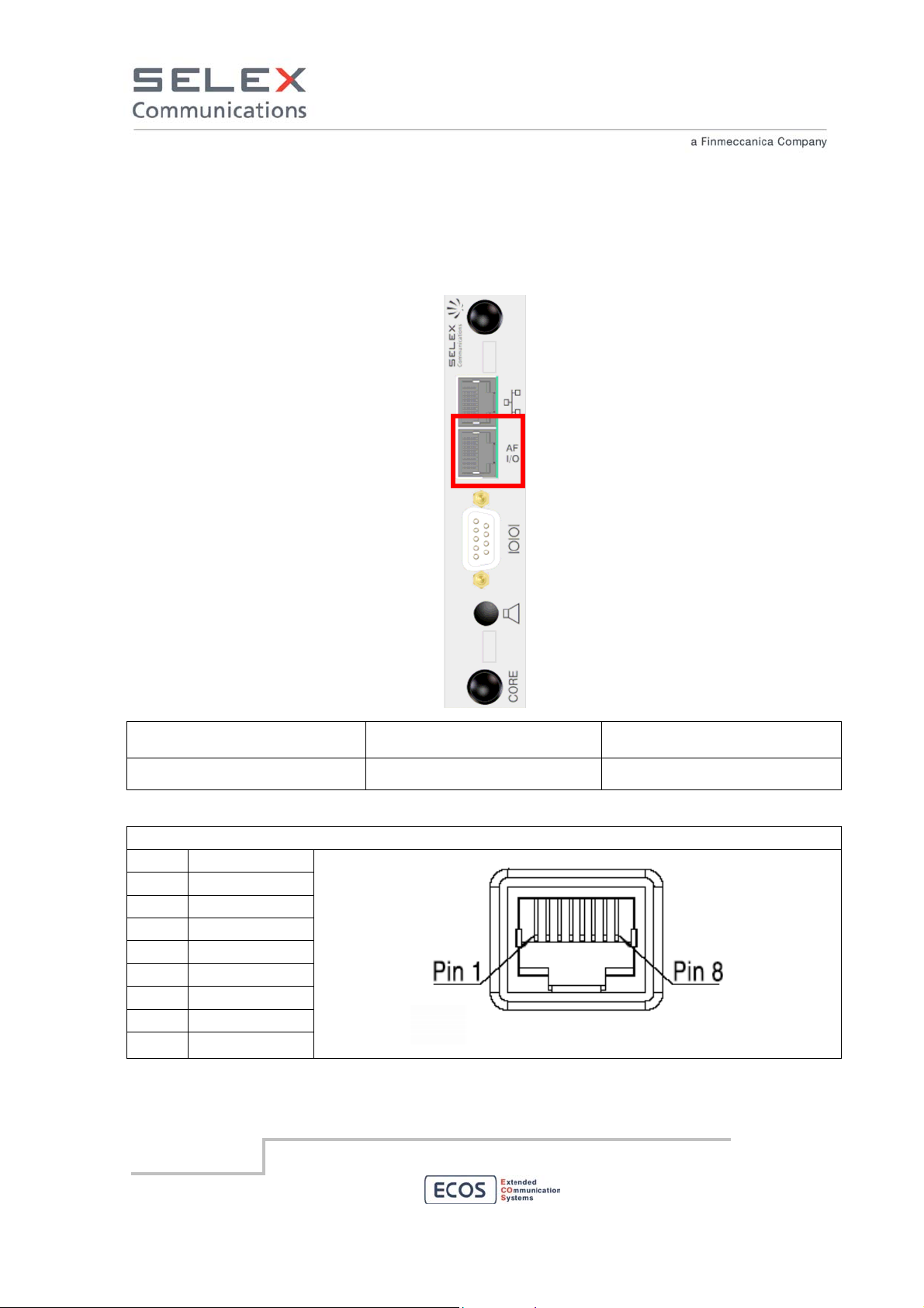
6.4.2 AF in/out
If the RBS is equipped with a CORE back card module a 4W+E/M link is available. The following
figure shows the rear panel of the CORE module. Configuration of this AF link is out of the scope of
this manual. Usually it is used to provide an AF signal to a third party audio device.
Link to external AF
Interconnecting points Type of connector terminating
Type of cable/conductor
the cable
4W or 4W+E/M Link RJ45 male connector AWG 24 Category 5
AF 4W+E/M line RJ45 female pinout
PIN
1 Mouth (M+)
2 Mouth (M-)
3 Ear (E+)
4 AF_OUT (-)
5 AF_OUT (+)
6 Ear (E-)
7 AF_IN (-)
8 AF_IN (+)
SELEX Communications
July 2010
Information contained in this document may not be used, applied or reproduced for any purpose unless agreed
by SELEX Communications S.p.A. in writing
30
Page 31
4W+E/M line usage
PIN 4W+E/M
1 M (+) Mouth signal +
2 M (-) Mouth signal -
3 E (+) Ear Signal +
4 AF_OUT (-) 600 Ohm Balanced OUT AF
5 AF_OUT (+) 600 Ohm Balanced OUT AF
6 E (-) Ear Signal -
7 AF_IN (-) 600 Ohm Balanced IN AF
8 AF_IN (+) 600 Ohm Balanced IN AF
E/M pin usage
PIN
Balanced Unbalanced
1 M (+) Mouth signal + Mouth signal
2 M (-) Mouth signal - not connected
3 E (+) Ear Signal + Ear Signal
6 E (-) Ear Signal - not connected
E/M Hardware Line settings
For unbalanced settings connect the two communicating entities to the same ground.
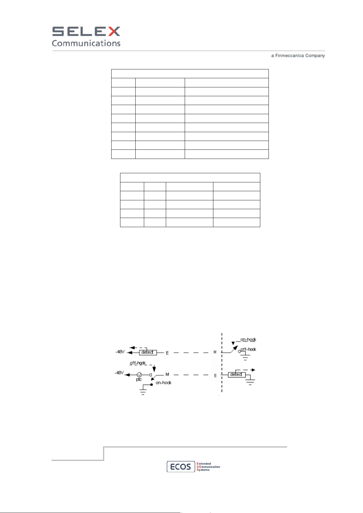
E/M Type I Interface Model
E/M Type I is the original E/M lead signaling arrangement and it is the most common interface type in
North America. The following diagram displays the sent signal states for active/not active signaling.
The RBS grounds its M−lead to signal a seizure. The other device applies battery to its M−lead to
signal a seizure. The RBS expect to see active conditions on the E−lead and signal active to the
remote device on M−lead.
RBS side
E/M Type II Interface Model
E/M Type II provides a four−wire fully−looped arrangement that provides full isolation between the
trunks and signaling units. The following table displays the sent signal states for active/not active
SELEX Communications
July 2010
Information contained in this document may not be used, applied or reproduced for any purpose unless agreed
by SELEX Communications S.p.A. in writing
31
Page 32

signaling. The RBS grounds its M−lead to signal a seizure. The other device applies battery to its
M−lead to signal a seizure. The RBS expect to see active conditions on the E−lead and signal active
to the remote device on M−lead.
M+
M-
E+
E-
RBS side
E/M Type V Interface Model
E/M Type V interface is a symmetrical two−wire lead arrangement that signals in both directions by
means of open for not active and ground for active signalling. The following table displays the sent
signal states for active/not active signaling. The RBS grounds its M−lead to signal a seizure. The other
device applies battery to its M−lead to signal a seizure. The RBS expect to see active conditions on
the E−lead and signal active to the remote device on M−lead.
RBS side
E/M Proprietary Type Interface Model
E/M Proprietary Type provides a four−wire fully−looped arrangement that provides full isolation
between the trunks and signaling units. The following table displays the sent signal states for
active/not active signaling. The RBS grounds its M−lead to signal a seizure. The other device applies
battery to its M−lead to signal a seizure. The RBS expect to see active conditions on the E−lead and
signal active to the remote device on M−lead.
SELEX Communications
July 2010
Information contained in this document may not be used, applied or reproduced for any purpose unless agreed
by SELEX Communications S.p.A. in writing
32
Page 33

M+
M-
E+
E-
+48v
RBS side
E/M Hardware settings
Type I
(Unbalanced)
Type II
(Balanced)
Type V
(Unbalanced)
proprietary
(Balanced)
IP1 1 ON OFF OFF ON
2 ON OFF OFF ON
IP2 1 OFF ON ON OFF
2 OFF ON ON OFF
IP3 1 OFF OFF OFF OFF
2 ON OFF ON OFF
IP1
IP2
IP3
SELEX Communications
July 2010
Back card deep switch positioning
Information contained in this document may not be used, applied or reproduced for any purpose unless agreed
by SELEX Communications S.p.A. in writing
33
Page 34

6.5 Syncronization Interfaces
6.5.1 Main GPS Interface
In order to connect the Main GPS antenna to the RBS, connect the GPS antenna to the SMA-BNC
“Main GPS” connector shown in the following figure.
Main GPS Antenna
Spare GPS Antenna
Interconnecting points Type of connector terminating
Type of cable/conductor
the cable
GPS SMA male connector 50 ohm coaxial cable with
double shield
SELEX Communications
July 2010
Information contained in this document may not be used, applied or reproduced for any purpose unless agreed
by SELEX Communications S.p.A. in writing
34
Page 35

6.6 Other Interfaces
6.6.1 Door break-in
Insert the connector in the front or rear door break-in connector shown in the following figure.
Front Door Break-in
Rear Door Break-in
Connect the three devices to the cable coming from the door as shown in the following figure.
SELEX Communications
July 2010
Information contained in this document may not be used, applied or reproduced for any purpose unless agreed
by SELEX Communications S.p.A. in writing
35
Page 36

6.6.2 LAN Interface
The LAN Interface is a 10BASE-T 100BASE-TX autosensing Ethernet interface with a standard RJ45
connector. Connect it to a hub/switch to provide LAN access to the feature of the RBS. Available
features depend on the settings of the RBS.
LAN port
Interconnecting points Type of connector terminating
Type of cable/conductor
the cable
LAN RJ45 male connector AWG 24 Category 5
SELEX Communications
July 2010
Information contained in this document may not be used, applied or reproduced for any purpose unless agreed
by SELEX Communications S.p.A. in writing
36
Page 37

LAN RJ45 female pinout
PIN
1 RX+ Receive Data +
2 RX- Receive Data -
3 TX+ Transmit Data +
4 not used
5 not used
6 TX- Transmit Data -
7 not used
8 not used
LAN RJ45 male cabling
PIN
EIA/TIA 568A EIA/TIA 568B
1 TX+ White/Green White/Orange
2 TX- Green Orange
3 RX+ White/Orange White/Green
4 Blue Blue
5 White/Blue White/Blue
6 RX- Orange Green
7 White/Brown White/Brown
8 Brown Brown
To connect the RBS to an Ethernet hub/switch use a straight cable (EIA/TIA 568A or EIA/TIA 568B on
both ends).
To connect the RBS directly to an Ethernet host use a cross cable (EIA/TIA 568A on one end and
EIA/TIA 568B on the other end).
SELEX Communications
July 2010
Information contained in this document may not be used, applied or reproduced for any purpose unless agreed
by SELEX Communications S.p.A. in writing
37
Page 38
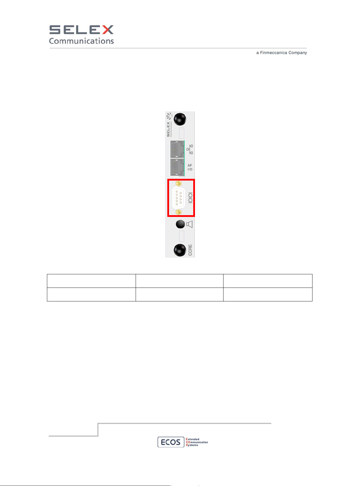
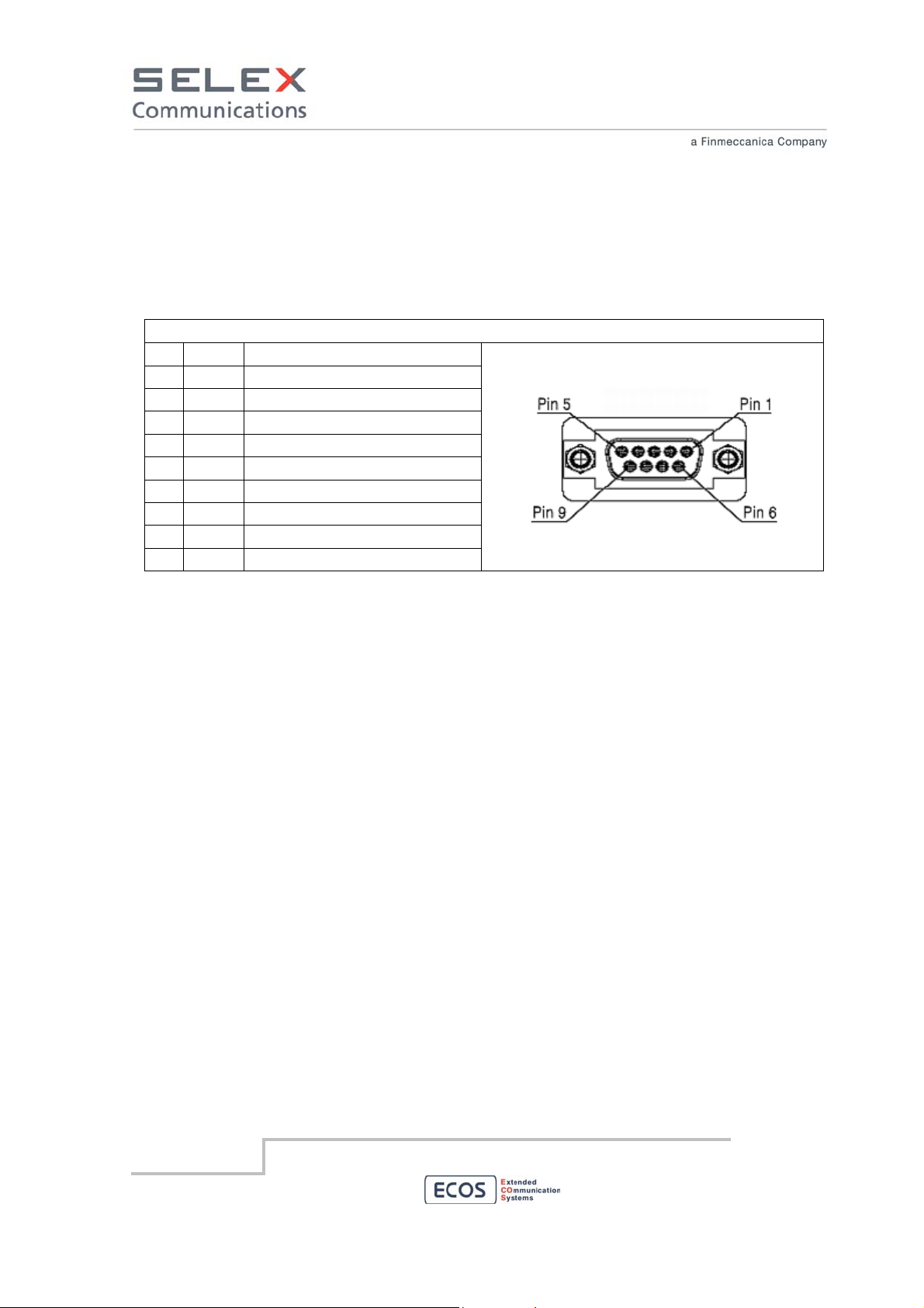
6.6.3 Serial Interface
The Serial Interface is an RS232 interface with a standard female type D DCE connector. Connect it to
a DTE to provide serial access to the RBS. Available features depend on the settings of the RBS.
Serial Interface
Interconnecting points Type of connector terminating
the cable
RS232 Male type D connector with 9
pins and shielded holder
Type of cable/conductor
9 conductor cable with double
brass sheath type interconductor
SELEX Communications
July 2010
Information contained in this document may not be used, applied or reproduced for any purpose unless agreed
by SELEX Communications S.p.A. in writing
38
Page 39

RS232
RS232 standards are defined by EIA/TIA (Electronic Industries Alliance /Telecommunications Industry
Association). RS232 defines both the physical and electrical characteristics of the interface. RS232 is
an Active LOW voltage driven interface and operates at +12V to -12V. RS232 is a serial interface for
the transmission of point to point digital data. Description of the connector’s pins is from DTE to DCE.
The RBS acts as a DCE.
RS232 female pinout
PIN
Mean
1 not used
2 RX Data from DCE to DTE
3 TX Data from DTE to DCE
4 not used
5 GND Ground
6 not used
7 RTS Ready To Send (from DTE)
8 CTS Clear To Send (to DTE)
9 not used
Complete RS232 female pinout (only on request)
PIN
Mean
1 not used
2 RX Data from DCE to DTE
3 TX Data from DTE to DCE
4 DTR Data Terminal Ready (from DTE)
5 GND Ground
6 DSR Data Set Ready (to DTE)
7 RTS Ready To Send (from DTE)
8 CTS Clear To Send (to DTE)
9 not used
SELEX Communications
July 2010
Information contained in this document may not be used, applied or reproduced for any purpose unless agreed
by SELEX Communications S.p.A. in writing
39
Page 40

A
6.6.4 Auxiliary Serial Interface
The Auxiliary Serial Interface is an optional RS232, RS422 or RS485 interface with a standard female
type D DCE connector. Connect it to a DTE to provide serial access to the RBS. Available features
depend on the settings of the RBS.
UX Serial Interface
Interconnecting points Type of connector terminating
the cable
RS232 RS422 RS485 Male type D connector with 9
pins and shielded holder
Pinout of the three tipes of serial interface are described below.
Type of cable/conductor
9 conductor cable with double
brass sheath type interconductor
SELEX Communications
July 2010
Information contained in this document may not be used, applied or reproduced for any purpose unless agreed
by SELEX Communications S.p.A. in writing
40
Page 41

RS232
RS232 standards are defined by EIA/TIA (Electronic Industries Alliance /Telecommunications Industry
Association). RS232 defines both the physical and electrical characteristics of the interface. RS232 is
an Active LOW voltage driven interface and operates at +12V to -12V. RS232 is a serial interface for
the transmission of point to point digital data. Description of the connector’s pins is from DTE to DCE.
The RBS acts as a DCE.
RS232 female pinout
PIN
Mean
1 not used
2 RX Data from DCE to DTE
3 TX Data from DTE to DCE
4 not used
5 GND Ground
6 not used
7 RTS Ready To Send (from DTE)
8 CTS Clear To Send (to DTE)
9 not used
RS422
RS422 is a balanced serial interface for the transmission of point to point digital data. The advantage
of a balanced signal is the greater immunity to noise. The EIA describes RS422 as a DTE to DCE
interface for point-to-point connections. Description of the connector’s pins is from DTE to DCE. The
RBS acts as a DCE.
RS422 female pinout (only on request)
PIN
Mean
1 GND Ground
2 TX + Data from DTE to DCE
3 not used
4 RX + Data from DCE to DTE
5 GND Ground
6 not used
7 TX - Data from DTE to DCE
8 not used
9 RX - Data from DCE to DTE
SELEX Communications
July 2010
Information contained in this document may not be used, applied or reproduced for any purpose unless agreed
by SELEX Communications S.p.A. in writing
41
Page 42
RS485
RS485 is a balanced serial interface for the transmission of digital data. The advantage of a balanced
signal is the greater immunity to noise. Point to point or multi-point behaviour of this serial interface is
software dependent and is out of the scope of this manual. Description of the connector’s pins is from
DTE to DCE. The RBS acts as a DCE.
RS485 female pinout (only on request)
PIN
Mean
1 not used
2 RTX + Data
3 not used
4 not used
5 GND Ground
6 not used
7 RTX - Data
8 not used
9 not used
SELEX Communications
July 2010
Information contained in this document may not be used, applied or reproduced for any purpose unless agreed
by SELEX Communications S.p.A. in writing
42
Page 43

6.6.5 Digital Input/Output Interface
The RBS manages 4 digital outputs. The connector is located on the rear of the RBS and is shown in
red in the following figure.
I/O Interface
Interconnecting points Type of connector terminating
Type of cable/conductor
the cable
User I/O Socket block B2L 3.5/20LH Section of each wire ≤ 1 sq.mm.
(AWG 18)
SELEX Communications
July 2010
Information contained in this document may not be used, applied or reproduced for any purpose unless agreed
by SELEX Communications S.p.A. in writing
43
Page 44

I/O Socket block B2L male pinout
type contact
out 1 power supply alarm (*)
out 2 temperature alarm (*)
out 3 synchronization alarm (*)
out 4 RF power alarm (*)
in 1 not used
in 2 not used
in 3 not used
in 4 not used
in A1 not used
in A2 not used
(*) The meaning of the digital outputs depends on the firmware release of the RBS.
In the shown example the meaning is as follows:
Output 1: power supply alarm. When the RBS is supplied from battery the output is closed.
Output 2: RBS temperature alarm. When the temperature is over a defined maximum value the
output is closed.
Output 3: RBS synchronization alarm. When the RBS loses synchronisation the output is closed.
Output 4: RF power alarm. When the PA transmitting power is 3 dB below the right power level the
output is closed.
SELEX Communications
July 2010
Information contained in this document may not be used, applied or reproduced for any purpose unless agreed
by SELEX Communications S.p.A. in writing
44
Page 45
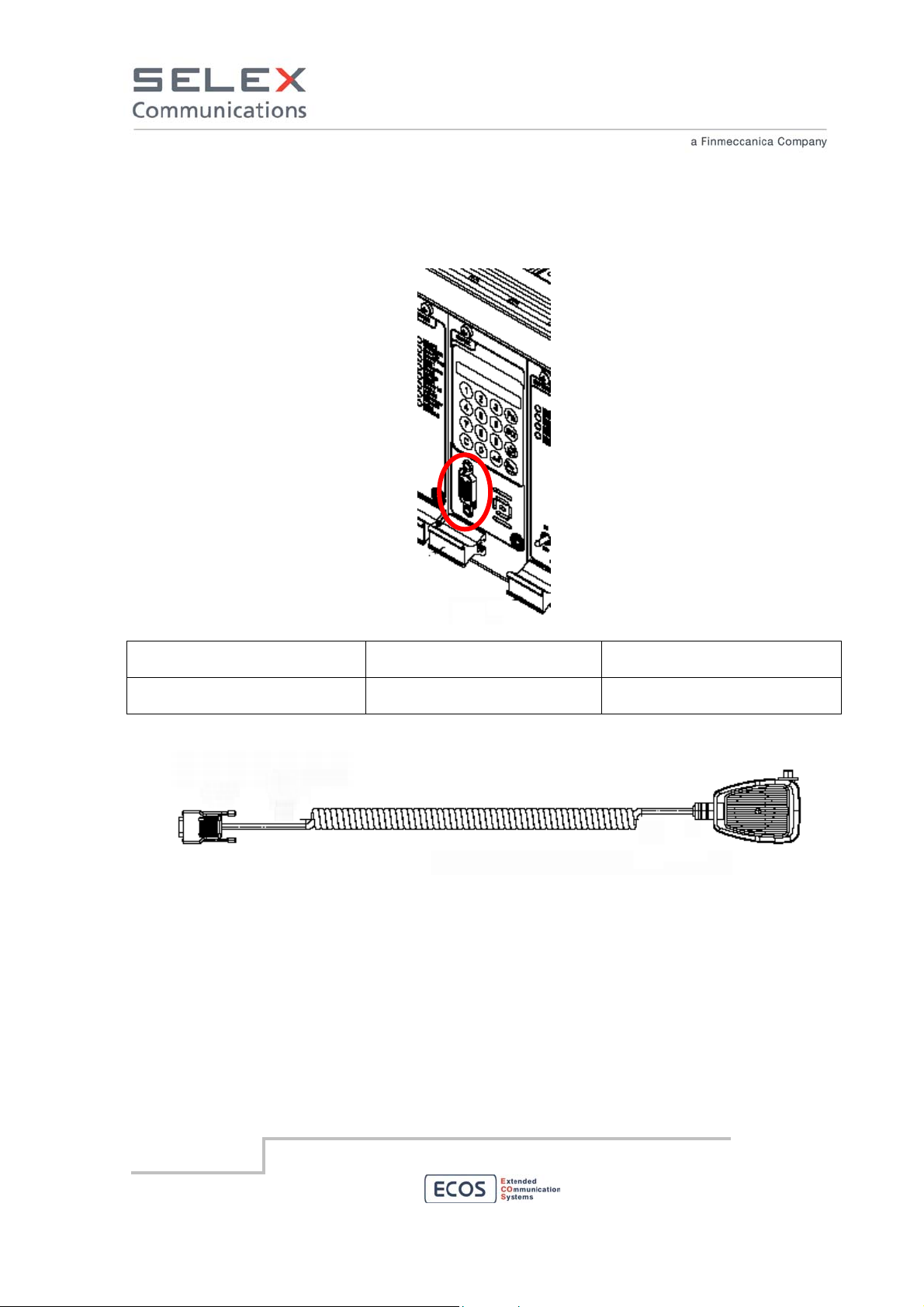
6.6.6 Local Microphone Interface
The local microphone interface permits to connect a microphone to the RBS. Features related with
PTT press and the AF of the microphone are out of the scope of this manual.
Local Microphone Interface
Interconnecting points Type of connector terminating
the cable
Microphone Male type D high density
connector with 15 pins
Microphone
Type of cable/conductor
Section of each wire ≤ 1 sq.mm.
(AWG 18)
SELEX Communications
July 2010
Information contained in this document may not be used, applied or reproduced for any purpose unless agreed
by SELEX Communications S.p.A. in writing
45
Page 46
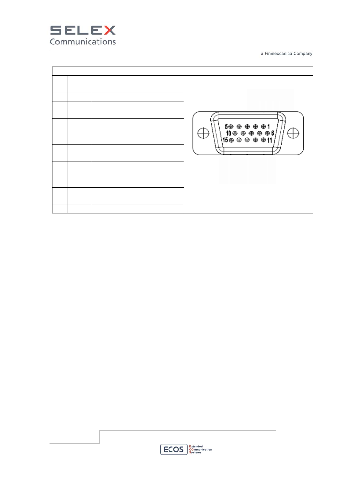
D-SUB HD 15 female pinout
PIN
Mean
1 GND Ground
2 not used
3 not used
4 not used
5 not used
6 AF in Audio Frequency input to RBS
7 not used
8 not used
9 not used
10 not used
11 PTT Push To Talk input to RBS
12 not used
13 DGND Digital Ground
14 not used
15 VDD
(soldering side view)
SELEX Communications
July 2010
Information contained in this document may not be used, applied or reproduced for any purpose unless agreed
by SELEX Communications S.p.A. in writing
46
Page 47
7. Configuration
The hardware configuration, where applicable, is described in the installation section of this manual.
Hardware configuration is limited only to hardware related characteristics such as electrical interfaces.
A parameter configuration must be done to adjust each device to the user need. This procedure is
described in the manual of the configuration software. Please refers to it for more information.
A list of values for each parameter for each device is provided in a separate document on demand.
Please refer to it to set the proper value for each parameter.
To connect the PC with the configuration software to the RBS follow the procedure described in the
Local Maintenance Interface section.
8. Maintenance
8.1 Module features, alarms and troubleshooting
8.1.1 CORE module
The CORE module, for its versatility and potentiality, is the core of ECOS-D RBS.
This module is equipped with devices for numerical computation (DSP, FPGA) and
control (microprocessor).
The primary functionalities of the Core Module are:
• MMI (Man Machine Interface) to allow an operator to interact with the
device
• Main Simulcast Management, implementing the voting algorithm,
equalization and a matrix of AF signals.
• local and remote management of the device.
The module is able to receive the input reference source from multiple clock signals:
• Internal GPS receiver (up to 2)
• AF tone (eg, tone at 3400 Hz via from an external source through LIF or DIF module)
• 2,048 MHz (G.703)
The choice of input clock signal is performed according to a configurable logic that normally assigns
higher priority to the GPS signal.
The module provides as its output the following clock signals to all the other modules of the RBS:
• RBS main reference clock (26 MHz)
SELEX Communications
July 2010
Information contained in this document may not be used, applied or reproduced for any purpose unless agreed
by SELEX Communications S.p.A. in writing
47
Page 48

• PPS main and / or spare
The CORE module can accommodate also two option boards:
• The SoIP piggy back (Simulcast over IP) that allows the CORE module to manage IP link
towards other RBS
• The Vocoder piggy back, that allows the CORE module to manage the digital voice
The CORE MMI makes available to a technical operator the following functionalities.
• Radio frequencies settings (RX e TX);
• RF transmission power settings (Hi / Low);
• Enable / disable of input/output lines (radio and wired);
• Speak and listen on selectable interfaces;
• Measures:
o power supply (V);
o RSSI (dBm);
o RF transmit power (dBm);
• voted signal;
• Selection and management of Audio Frequency (AF) signals for test purposes;
• Lock / unlock of voice in local speaker (radio squelch or criterions);
• Speaker volume setting;
• Display brightness setting;
• Menu language setting;
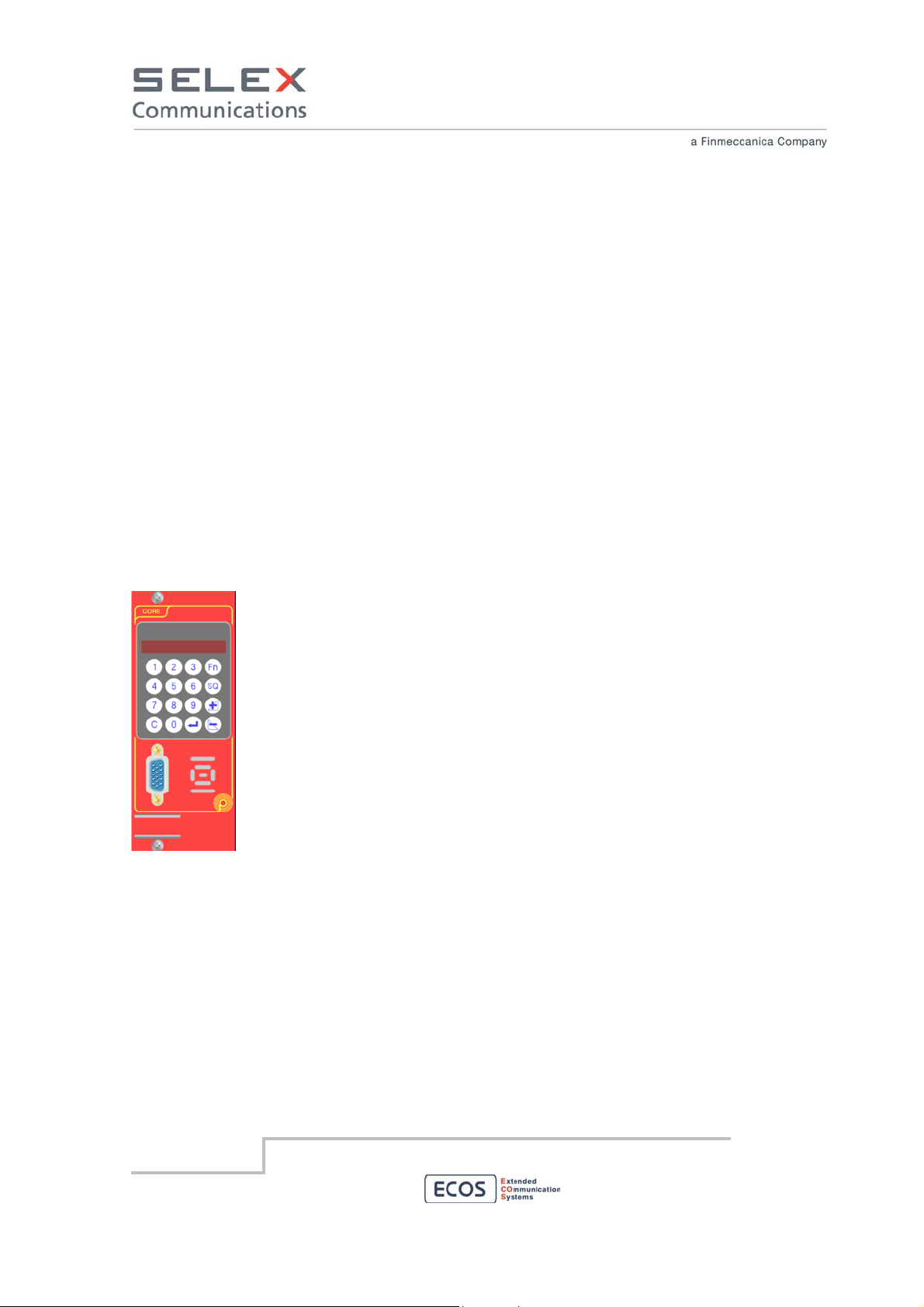
The MMI is composed by a 8 characters display (each character is 5 x 7 pixels) and a Keypad
The keypad is composed by 16 buttons: SQ (Squelch), Fn (Function), +, -,
↵, C (cancel) and 0 ÷ 9. In
the following a brief summary of their use is given.
SQ Use it to open/close the analog squelch of the device
Fn Use it to switch between stand-by mode and menu mode.
+ / - These are multi-function buttons: they are used for navigation in menu, to up and down
speaker volume and display brightness.
↵ in menu mode use it to confirm the choice.
C In menu mode use it to go back to previous menu.
SELEX Communications
July 2010
Information contained in this document may not be used, applied or reproduced for any purpose unless agreed
by SELEX Communications S.p.A. in writing
48
Page 49
0 ÷ 9 In menu mode use them to insert the value of parameters where required
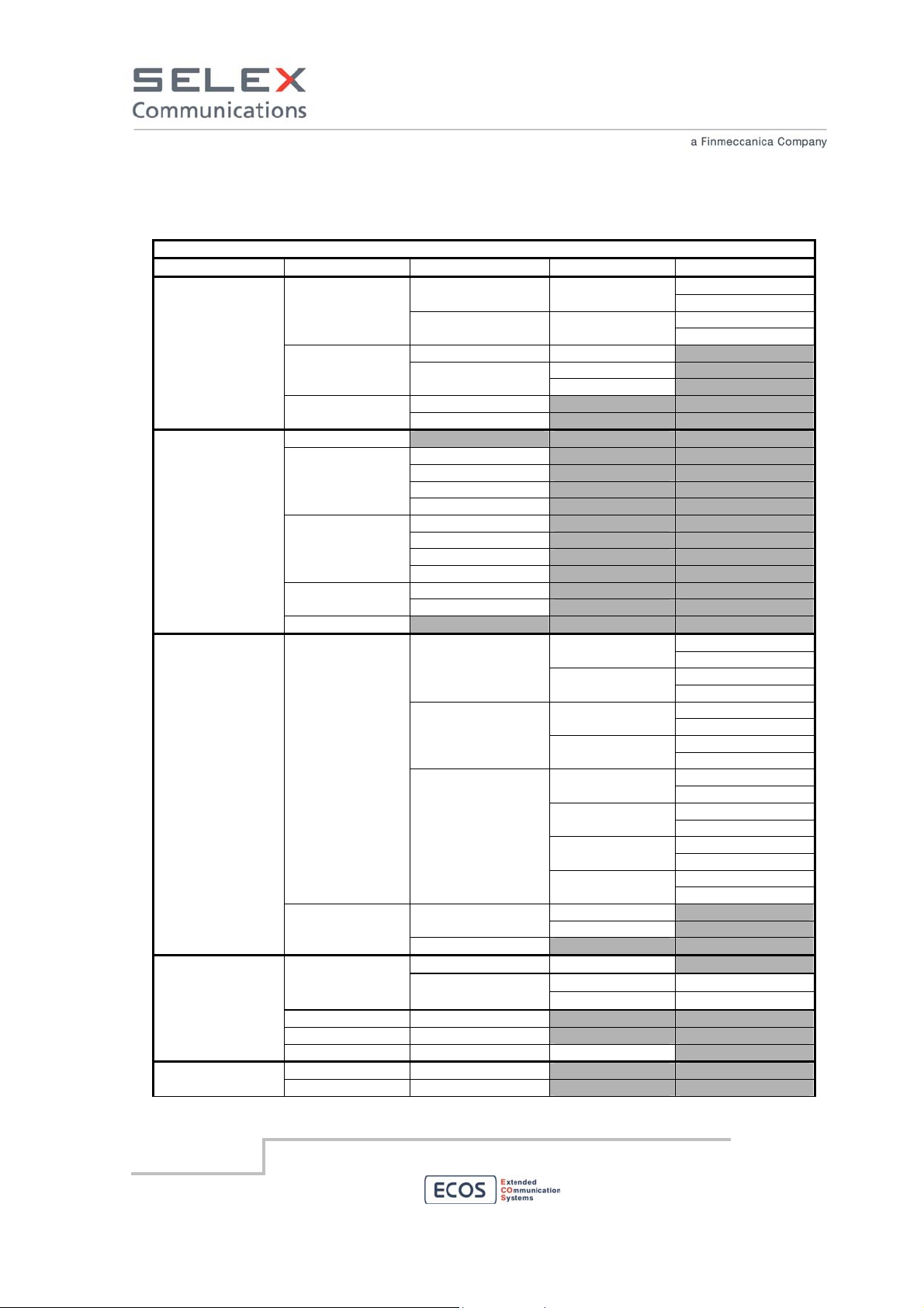
The menu tree is described in the following table.
Menu level
1 2 3 4 5
1. Settings
2. Spk/Lstn
3. Commands
4. Measure
1. Radio
2. RF Power PA
2. Display
1. Brightn.
2. Language
Italiano
English
3. Network
1. IP Address
2. Net mask
RTX
LIF
1. L1
2. L2
3. L3
DIF
4. L4
1. L1
2. L2
3. L3
4. L4
1. RRXa RRX
2. RRXb
CORE
1. Inhibit
RTX
2. TX
RRX
2. RXb
LIF
L4
2. Voice
1. TS 1 1. Digital
2. TS 2
2. Analog
1. RSSI
RTX
RRX
RRXa
RRXb
2. DC
3. Voter
4. RF Power PA
RTX 5. AF Test
LIF 1. L1
1. Freq.RX 1. View Freq. RTX
2. Freq.TX
1. Low
2. Hi
ON 1. RX
OFF
ON
OFF
ON 1. RXa
OFF
ON
OFF
ON L1
OFF
ON L2
OFF
ON L3
OFF
ON
OFF
SELEX Communications
July 2010
Information contained in this document may not be used, applied or reproduced for any purpose unless agreed
by SELEX Communications S.p.A. in writing
49
Page 50

1 2 3 4 5
6. Status
3. Sync. Log
7. Diagnostic
2. Err Log
Menu level
2. L2
3. L3
4. L4
ON 1. Monitor
OFF
M GPS 2. GPS FIX
S GPS
List
Cancel
ON 1. Monitor
OFF
List
Cancel
SELEX Communications
July 2010
Information contained in this document may not be used, applied or reproduced for any purpose unless agreed
by SELEX Communications S.p.A. in writing
50
Page 51
8.1.2 4 Lines Interface module – LIF
The "4 Lines Interface” (LIF) module is the module that is able to manage up to 4 lines with
4W interface + (E&M). This module is equipped with devices for numerical computation
(DSP, FPGA) and control (microprocessor) combined with the electrical interfaces for the 4
wires lines.
The “Line Interface” (LIF) module is also able to manage redounded links over the 4 wires
interfaces.
4 wires interfaces are used by the device to connect this Radio Base Station to up to other 4
Radio Base Stations to build a Simulcast network.
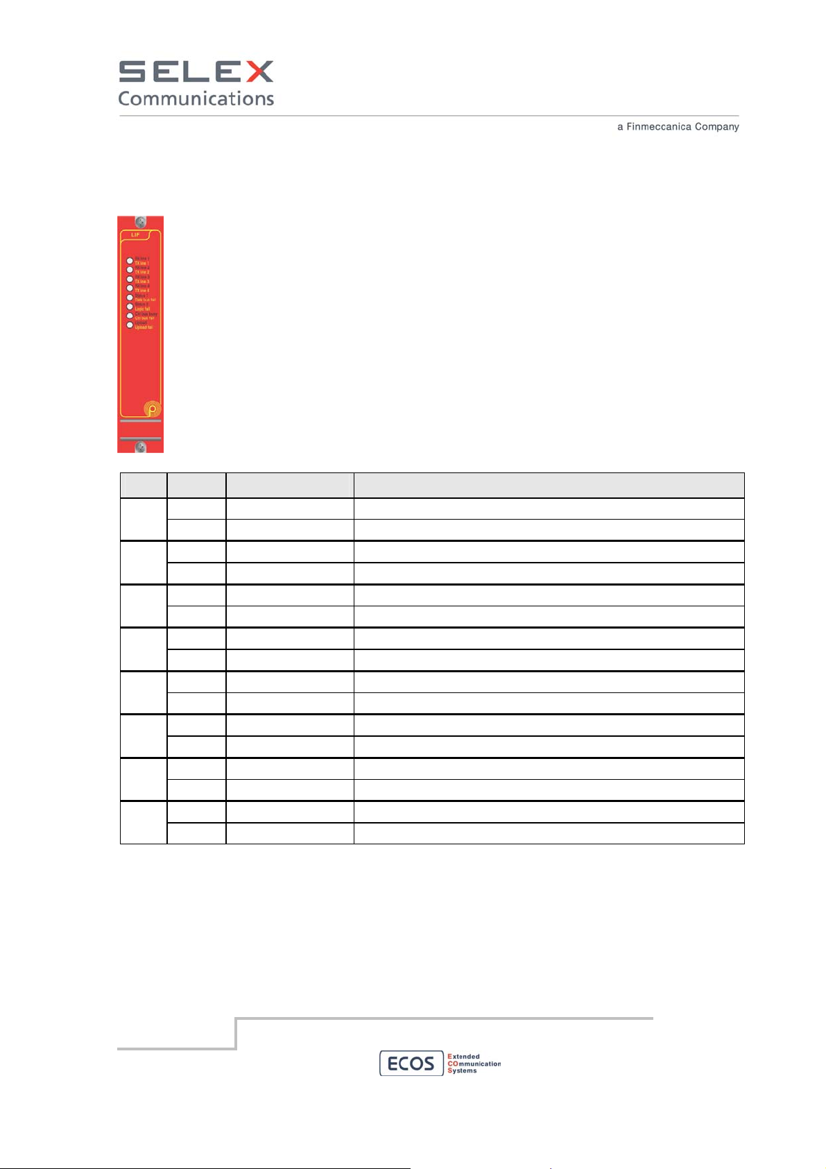
The front panel is provided with bi-color leds to help in troubleshooting the system. The table
below describes the meaning of the leds:
LED
Color Label Description
1 Green
Red
2 Green
Red
3 Green
Red
4 Green
Red
5 Green
Red
6 Green
Red
7 Green
Red
8 Green
Red
Line 1 RX Line 1 on RX
Line 1 TX Line 1 on TX
Line 2 RX Line 2 on RX
Line 2 TX Line 2 on TX
Line 3 RX Line 3 on RX
Line 3 TX Line 3 on TX
Line 4 RX Line 4 on RX
Line 4 TX Line 4 on TX
Status1
DATA bus fail failure MTCH of DSP
Status2
Logic fail µP and DSP not communicate
CTRL bus busy Activity on Control Bus
CTRL bus fail failure of BUS µP
Upload Ongoing download code
Upload Fail Download code KO
SELEX Communications
July 2010
Information contained in this document may not be used, applied or reproduced for any purpose unless agreed
by SELEX Communications S.p.A. in writing
51
Page 52

8.1.3 SWITCH module
The Switch module realizes a "solid state" switch (MOSFET) device for the distribution of the
power necessary for the proper working of all the modules of the ECOS-D RBS. In particular
its primary task is to distribute the 13,2 Vdc nominal voltage (Master voltage) and 7 Vdc
nominal voltage (Slave voltage).
The 7 Vdc Slave voltage is used by all the other modules to power their logic. It is generated
by the switch module for direct conversion from the 13,2 Vdc Master voltage.
The switch module provides:
• ON / OFF of all the modules on the same RBS
• Protection against Extra Current (short circuit or overload > 22 A ± 5%)
• Protection against Extra voltage (maximum input voltage equal to 30 Vdc ± 5%)
• Protection against voltages outside the guaranteed operating range [10.8 ÷ 15.6 Vdc].
• Protection against reverse polarity input voltage.
• Protection against over temperature inside the module itself (≥ 100 ° C ± 1%).
The front panel is provided with bi-color leds to help in troubleshooting the system. The table below
describes the meaning of the leds:
LED
1 Green
Red
2 Green
Red
3 Green
Red
Red
Color Label Description
Vin OK Normally operating
Vin fail Input voltage out of range
Vout ok RBS internal voltage levels are correct
Vout fail RBS internal voltage failure
Control bus busy Activity on the control bus
Control bus fail control bus among the modules is in failure
Control bus fail Bad message received
blink
4 Green
Upload Firmware upload in progress
Red
SELEX Communications
July 2010
Upload fail Firmware upload failed
Information contained in this document may not be used, applied or reproduced for any purpose unless agreed
by SELEX Communications S.p.A. in writing
52
Page 53

8.1.4 DC/DC module
The DC/DC module is a continue power voltage converter from an external
power source to the internal power level of ECOS-D devices. The converter,
other than the power voltage conversion, is able to galvanically insulate
(1500Vrms) the internal 13,2 Vdc power distribution from the external power
source and a 28 Vdc power distribution to the 110W PA module.
LED
1 Green
Red
2 Green
Red
Color Label Description
Vout OK Normally operating
NA
Vin OK Normally operating
NA
8.1.5 Radio Receiver and Transmitter module - RTX
The “Radio Receiver and Transmitter” (RTX) module is the module that realizes a full duplex
radio in the frequency bands commonly used by in the LMR/PMR market (450 - 526 MHz). It
is able to operate with channel spacing of 12.5 kHz, 20 kHz and 25 kHz. Limitation on usable
RF bands and channel spacing may apply due to local regulations.
This module is equipped with devices for numerical computation (DSP, FPGA) and control
(microprocessor) combined with the radio receiver front-end and the transmitter driver.
The RTX module main functionalities are:
• Temperature control.
• UHF band: 450 – 526 MHz
SELEX Communications
July 2010
• Dynamic Dual mode radio operations with support of digital and analog
modulation
• Synchronization from external reference via CORE module
Information contained in this document may not be used, applied or reproduced for any purpose unless agreed
by SELEX Communications S.p.A. in writing
53
Page 54
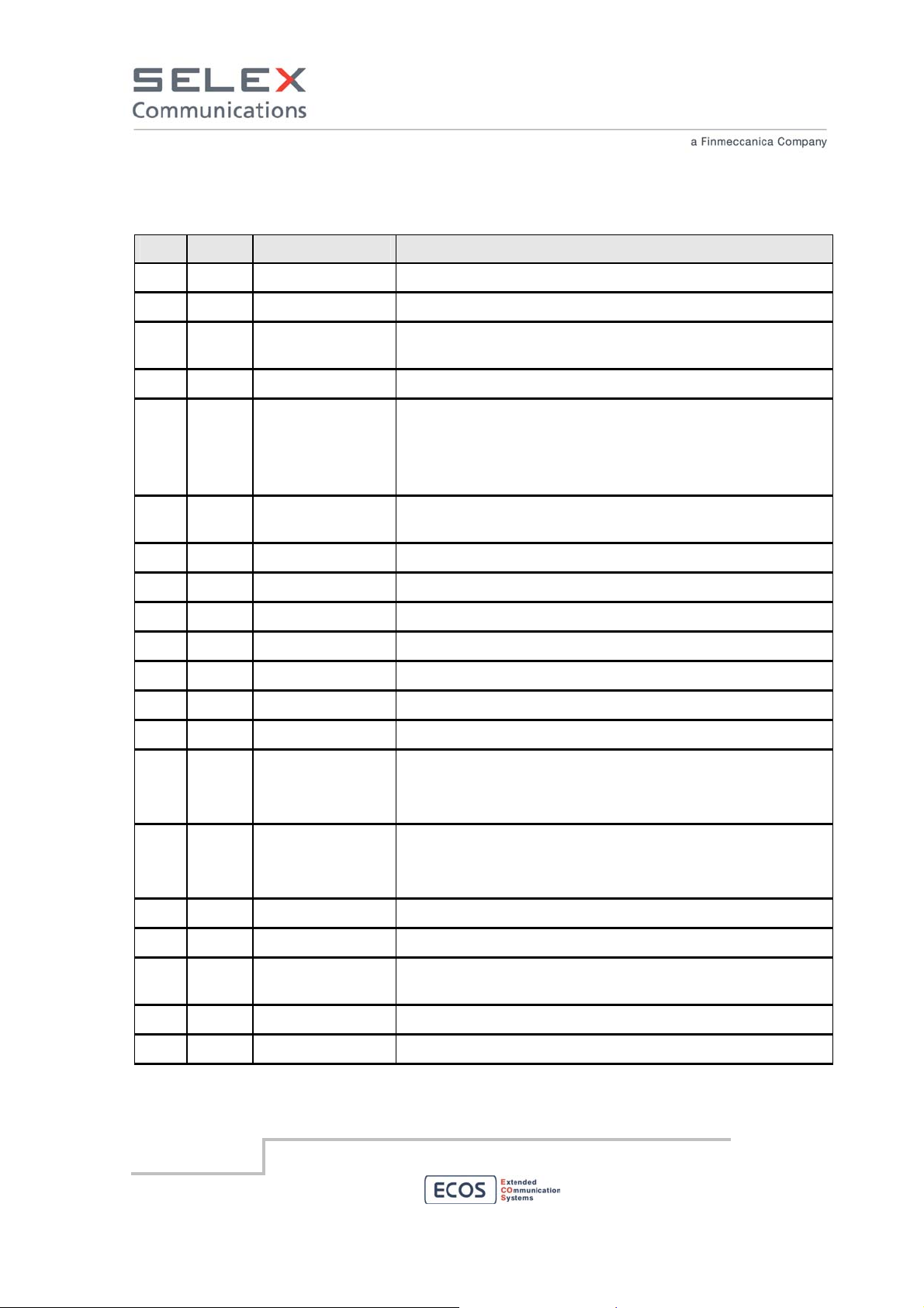
The front panel is provided with bi-color leds to help in troubleshooting the system. The table below
describes the meaning of the leds:
LED
Color Label Description
1 Green
Red
Red
blink
2 Green
Red
Red
blink
3 Green
Red
4 Green
Red
5 Green
RX busy RF signal present at the receiver
RX fail Receiver PLL unlock
RX fail RX Equalizer failure
TX on RF exciter correctly On Air
TX fail RF exciter failure:
- bad power out
- ACP failure
- Exciter PLL unlock
TX fail TX dynamic equalizer failure
Status 1 RF signal with analog modulation present at the receiver
RX inhibit Receiver is in inhibited state
Status 2 RF exciter correctly On Air with digital modulation
Tx inhibit Exciter is in inhibited state
Status 3 Reserved
Red
6 Green
Red
Red
blink
7 Green
Red
Red
blink
8 Green
Red
SELEX Communications
July 2010
Data bus fail The multichannel data bus is out of frame sync
Status 4 Reserved
Logic fail One of the these error is present:
- DSP/uP communication failure
- logic PLL unlock
Logic fail One of the these error is present:
- boot failure
- EEPROM failure
Control bus busy Activity on the control bus
Control bus fail control bus among the modules is in failure
Control bus fail Bad message received
Upload Firmware upload in progress
Upload fail Firmware upload failed
Information contained in this document may not be used, applied or reproduced for any purpose unless agreed
by SELEX Communications S.p.A. in writing
54
Page 55

8.1.6 Power Amplifier module - PA
The “Power Amplifier” (PA) module is a wide band RF amplifier in UHF (450 -
526 MHz).
Their time of TX ramp up/down is less than 1200 µsec. This makes the module
compatible with the stringent demands of digital transmission.
Thanks to a microprocessor mounted on board, the module is able to implement
the PUFF technology (Powerful Universal Forming Function) for the shaping of
transient power in order to obtain compliance with the rapid transient rules of
ACP (Adjacent Channel Power).
The microprocessor also manages completely the operation of the module: this
would remove any calibration procedures. All configuration changes are performed via software.
Other main functionalities are:
• continuous transmitter’s operations (100% duty cycle).
• Output power selectable between two values (Phi and Plo), each of which can be SW set to
a nominal value between 10 and 110 Watts.
• final stage protected against excessive mismatching output power. In the case that VSWR
remains above a set threshold (eg ReturnLoss = 5dB) for more than a fixed time, the
module is able to send an alert and the output power will not exceed a safety value (eg ≤
10watt).
• temperature threshold alarm: if the temperature remains above a set value for more than a
fixed time, the module is able to send an alert and will ensure that the RF output power will
not exceed a predetermined safe value.
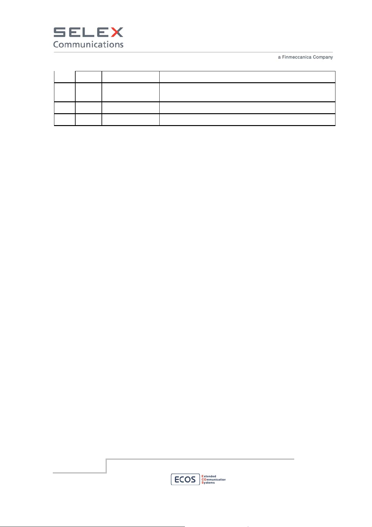
The front panel is provided with bi-color leds to help in troubleshooting the system. The table below
describes the meaning of the leds:
LED
1 Green
Color Label Description
PWR High High Power level selected and correctly On Air
Red
2 Green
Red
3 Green
SELEX Communications
July 2010
PWR fail Emitted power less than a FW configured threshold (3 dB
typical)
PWR low Low Power level selected and correctly On Air
VSWR On Air and VSWR level is greater than FW configured
threshold
Control bus busy Activity on the control bus
Information contained in this document may not be used, applied or reproduced for any purpose unless agreed
by SELEX Communications S.p.A. in writing
55
Page 56
Red
Red
Control bus fail control bus among the modules is in failure
Control bus fail Bad message received
blink
4 Green
Red
Upload Firmware upload in progress
Upload fail Firmware upload failed
SELEX Communications
July 2010
Information contained in this document may not be used, applied or reproduced for any purpose unless agreed
by SELEX Communications S.p.A. in writing
56
Page 57

8.2 Power modules maintenance precaution
Before maintenance operations involving power supply modules the power cable must be removed.
If the purpose of the maintenance is the replacement of the SWITCH or DC/DC modules the following
procedure must be followed:
48 Vdc powered devices:
• Switch off the device moving to the lower position the Main Power and Power switch.
Main Power on/off switch
Power on/off switch
• unplug the 48Vdc D-SUB 3W3 connector
• Remove the module as described in section 8.1.63.
SELEX Communications
July 2010
48 VDC input
Information contained in this document may not be used, applied or reproduced for any purpose unless agreed
by SELEX Communications S.p.A. in writing
57
Page 58

8.3 Module removal
To remove a module from the RBS follows the procedure described below.
1 – Unscrew the two (or four) screws marked in red on the front panel of the module
Module locking screws
2 – From the front side of the RBS using the handle marked in blue pull the module out.
Module handles
SELEX Communications
July 2010
Information contained in this document may not be used, applied or reproduced for any purpose unless agreed
by SELEX Communications S.p.A. in writing
58
Page 59

8.4 Back card removal
To remove a back card from the RBS follows the procedure described below.
1 – Unlock the two (or four) knobs marked in red on the panel of the back card
2 – From the rear side of the RBS using the same knobs pull the back card out.
SELEX Communications
July 2010
Information contained in this document may not be used, applied or reproduced for any purpose unless agreed
by SELEX Communications S.p.A. in writing
59
Page 60
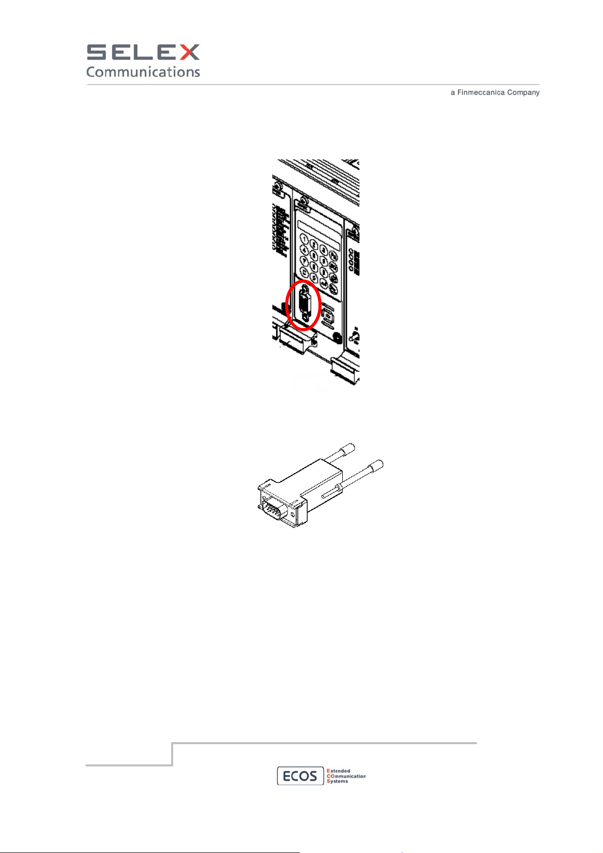
8.5 Local Maintenance Interface
The local maintenance interface is located on the front panel of the RBS on the CORE module.
Local Maintenance Interface
To perform local Maintenance and local configuration of the RBS, connect a PC to this connector
using the appropriate LAN adapter.
Maintenance LAN Adapter
SELEX Communications
July 2010
Information contained in this document may not be used, applied or reproduced for any purpose unless agreed
by SELEX Communications S.p.A. in writing
60
Page 61
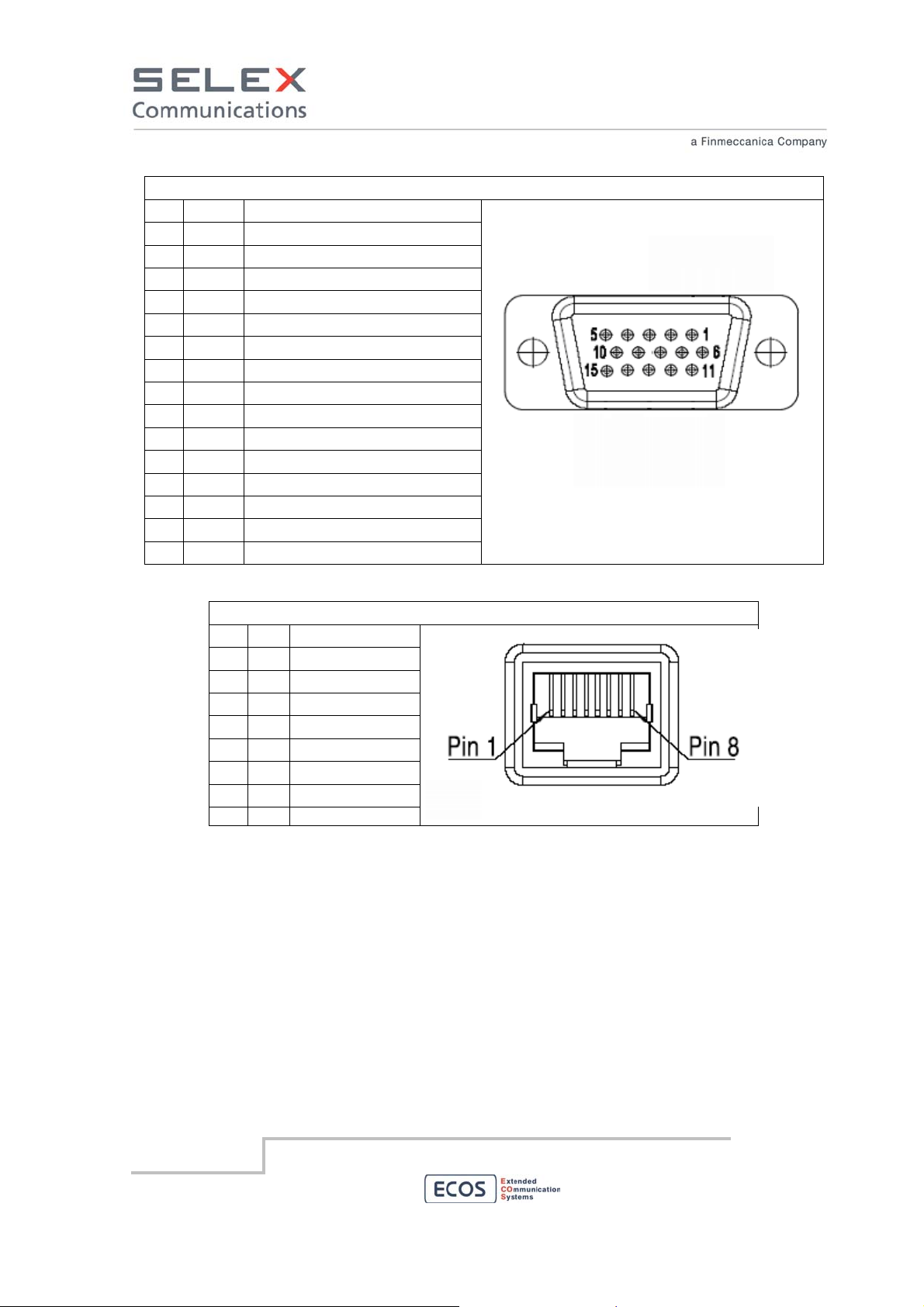
PIN
1 not used
2 not used
3 not used
4 not used
5 TX- Transmit Data -
6 not used
7 RX- Receive Data -
8 not used
9 TX+ Transmit Data +
10 not used
11 not used
12 RX+ Receive Data +
13 DGND Digital Ground
14 FLP Front LAN Presence
15 not used
D-SUB HD 15 female pinout
Mean
(soldering side view)
PIN
1 RX+ Receive Data +
2 RX- Receive Data -
3 TX+ Transmit Data +
4 not used
5 not used
6 TX- Transmit Data -
7 not used
8 not used
LAN RJ45 female pinout
SELEX Communications
July 2010
Information contained in this document may not be used, applied or reproduced for any purpose unless agreed
by SELEX Communications S.p.A. in writing
61
Page 62

8.6 Local Test AF Interface
The local Audio Frequency interface is located on the front panel of the RBS on the CORE module.
Use this interface to test the AF performance of the RBS.
Local Maintenance Interface
Interconnecting points Type of connector terminating
the cable
Microphone Male type D high density
connector with 15 pins
Type of cable/conductor
Section of each wire ≤ 1 sq.mm.
(AWG 18)
SELEX Communications
July 2010
Information contained in this document may not be used, applied or reproduced for any purpose unless agreed
by SELEX Communications S.p.A. in writing
62
Page 63
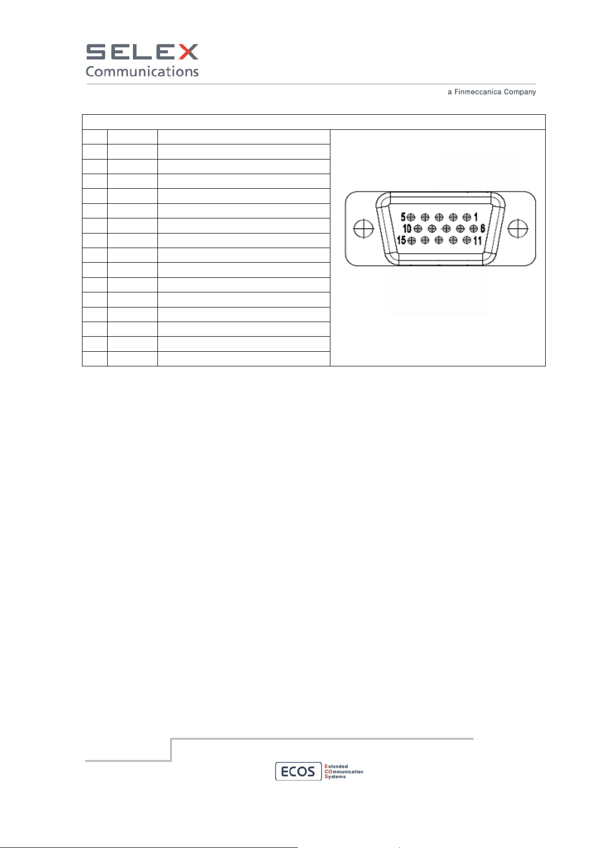
D-SUB HD 15 female pinout
PIN
Mean
1 GND Ground
2 AF FO Audio Frequency Output (no volume)
3 not used
4 AF out - Audio Frequency output from RBS
5 not used
6 AF in Audio Frequency input to RBS
7 not used
8 not used
9 not used
10 AF out + Audio Frequency output from RBS
11 PTT Push To Talk input to RBS
12 not used
13 DGND Digital Ground
14 not used
15 VDD
(soldering side view)
8.7 Remote Maintenance Interface
The Remote maintenance interface may be accessible directly or not on each RBS depending on the
configuration of the system.
If the RBS is configured to be remotely controlled via the LAN interface, see the LAN interface section
to correctly connect the RBS.
For more information about the remote maintenance procedure see the Network Management System
(NMS) Manual, where supplied.
SELEX Communications
July 2010
Information contained in this document may not be used, applied or reproduced for any purpose unless agreed
by SELEX Communications S.p.A. in writing
63
Page 64

SELEX Communications
July 2010
Information contained in this document may not be used, applied or reproduced for any purpose
unless agreed by SELEX Communications S.p.A. in writing. SELEX Communications S.p.A.
reserves the right to alter without notice the specification, design or conditions of supply of any
product or service. SELEX Communications logo is a trademark of SELEX Communications S.p.A.
Printed in Italy.
© SELEX Communications S.p.A. All Rights reserved.
Information contained in this document may not be used, applied or reproduced for any purpose unless agreed
by SELEX Communications S.p.A. in writing
64
 Loading...