

Page 1
1
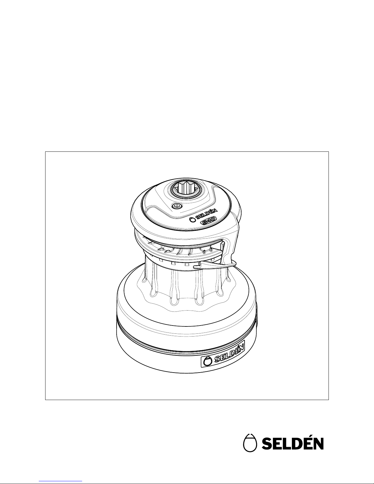
Manual for 2-speed self-tailing winches
S30, S40, S48 & S54
597-225-E
2016-06-01
Page 2

2
Contents
Page
1 Introduction 3
1.1 The manual 3
1.2 Warranty 3
1.3 General warning & instructions 4
1.4 Product information 4
1.4.1 Seldén winch range 4
1.4.2 S-winch feature 4
1.4.3 Winch handle 5
1.4.4 Technical data 5
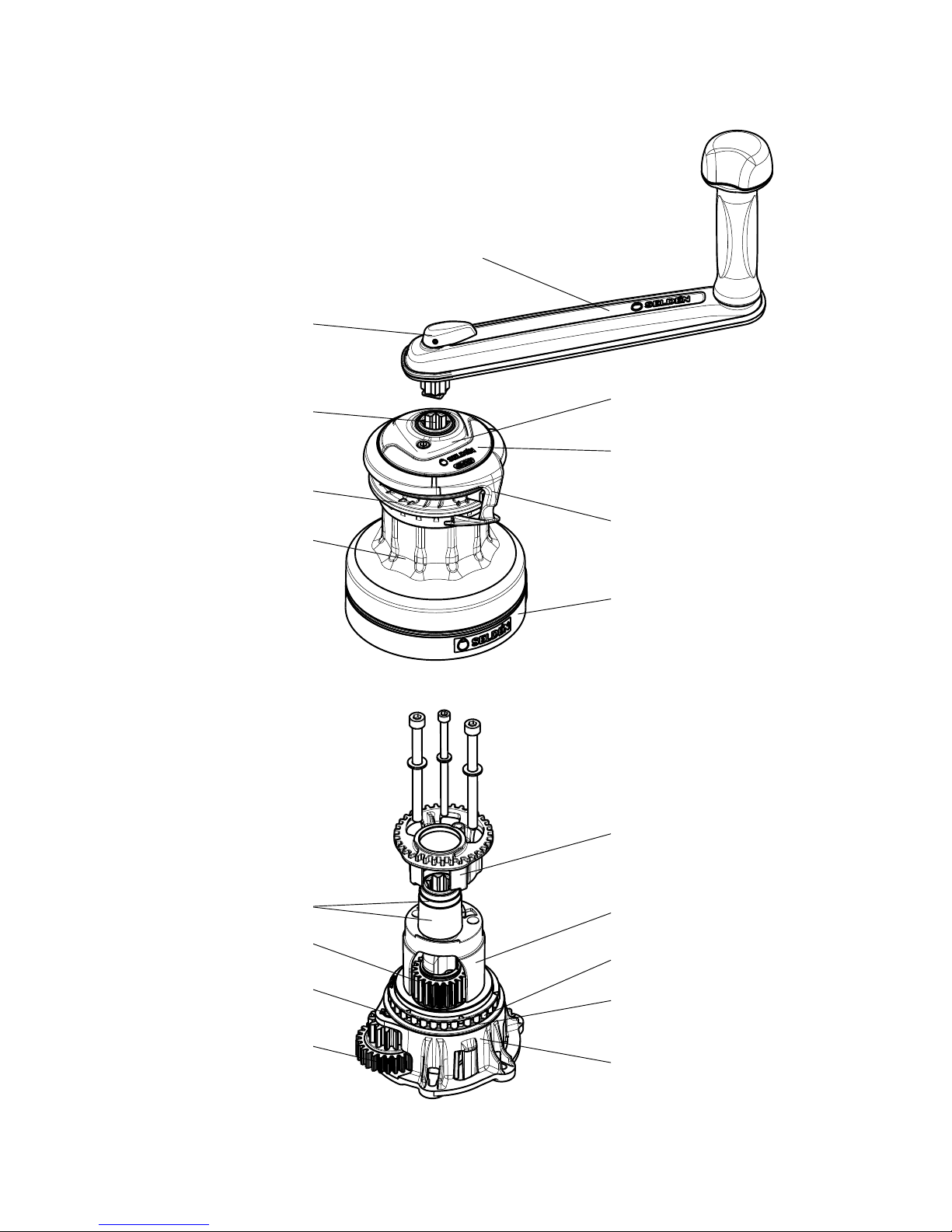
1.4.5 Parts and descriptions 6
2 Operation instructions 7
2.1 Winch handle 7
2.2 Winching 7
3 Installation 8
3.1 Installation preparations 8
3.1.1 Winching orientation 8
3.1.2 Line routing 8
3.2 Installation instructions 9
3.2.1 Installation with hexagon headed bolts
(Sliding bolts) 9
3.2.2 Adjustment of the self-tailing arm 10
3.2.3 Installation with hexagon socket head cap
screws (Allen screws) 11
4 Dismantling and maintenance 15
4.1 Dismantling for normal service 15
4.2 Dismantling for extended service 18
4.3 Service instructions 21
5 Notes 22
Page 3
3
1 Introduction
1.1 The manual
1.2 Warranty
To achive the maximum benet and enjoyment from your Seldén winch, we recommend that you study this
manual carefully.
All safety-related information is indicated by the following symbol:
The manual covers 4 different winch sizes; S30, S40, S48 and S54. The model designation can be found on the
top of the winch.
Identication-/serial number is located inside the winch, but also on the delivery box.
The Seldén winch installation system is based on metric screws/bolts.
This manual will be updated subsequently. For the latest update check www.seldenmast.com
Seldén Mast AB guarantees the winch for 2 years. The guarantee covers faults arising from defective design,
materials or workmanship.
The guarantee is only valid if the winch is installed, operated and maintained in accordance with this manual
and is not subjected to loads in excess of those indicated in the brochure and instructions.
If the winch is repaired by anyone else other than Seldén Mast AB or one of our authorized dealers, the guarantee ceases to be valid.
The Seldén winch is designed for line handling on sailboats only.
Complete shipment and warranty conditions are to be found on Seldén’s website www.seldenmast.com.
See Technical information/ General conditions of sale (595-546-E).
Seldén Mast AB reserves the right to alter the content and design without prior warning.
This information must be followed to avoid damage to the winch and risk of personal
injury. The 2-year warranty on the Seldén winch is only valid if the winch is installed
and operated correctly according to the manual.
Page 4
4
1.3 General warning & instructions
1.4 Product information
Make sure the winch is dimensioned according to Seldén’s design standards and not subjected to loads greater
than those stated in the brochure and instruction materials and is used solely for its intended use, i.e. normal
sailboat applications for running rigging.
Exceeding the stated maximum working load (MWL) may lead to winch failure or that the winch detaches from
the boat which may lead to serious injuries.
Keep hands, ngers, hair and clothing away from moving parts. It is recommended to let only one person, work
with the winch at any one time.
If a Seldén winch, despite the above, is used for going aloft in the mast, double halyards must be used, to be
hauled in and eased off at the same time. (Seldén rigging manual “Hints & Advice”, 595-540-E, “Working
aloft”).
For your own personal safety, make sure the winch is installed, regularly inspected and maintained according to
this manual.
This manual is available in English only. If you do not understand the manual content we advise you to obtain
expert assistance for the installation and operation!
Seldén have two ranges of winch, S-winches and the R-winches, which are manually operated and of selftailing type with two forward gears.
The difference between these two models are that the R-winches are revisable, which means it is possible to let
the line out by reversing the winch drum using the winch handle. The S-winches do not have this feature.
With modern manufacturing technology and by optimizing the choice of materials Seldén have succeeded to
reduce the weight and the need of maintenance to a minimum.
The drum has a unique design consist of several concave surfaces which provide an extraordinary grip for the
line. It means fewer turns on the drum which reduces the risk of an override and allows the line to be released
quickly.
The self-tailing jaws has a design which makes it possible to pull the slack out of the sheet with the line sitting
in the self-tailer and with the winch handle mounted. This means safer and quicker operation.
The Seldén winch is designed for line handling on sailboats only!
Exceeding maximum working load may lead to winch failure or serious injuries.
1.4.1 Seldén winch range
1.4.2 S-winch features
Page 5
5
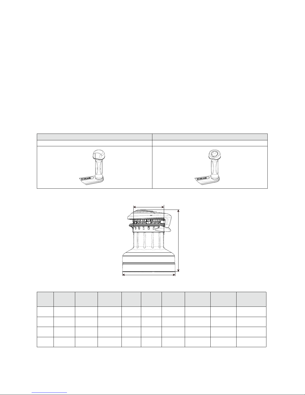
Seldén have two different models of winch handles designed for S-winches and R winches respectively. The
winch handle for the R-winches differs from the S-winch handle by it having a button for a reverse function on
the grip. Both winch handles t in each winch model and works for forward winching, while the reverse
function on R-winch only can be operated by the R-winch handle.
The S-winch has two different fastening methods:
1. By hexagon headed bolts which slide into a groove in the winch base and where the hexagon heads are
locked against rotation due to the winch base structure. This method allows installation without dismantling
the winch. The bolts are tted through deck and fastened using washers and nuts. (See g.3.2.1.c).
2. By hexagon socket head cap screws (Allen screws) mounted from above. The winch needs to be dismantled. E.g. for cases where the boat is prepared with metal inserts in the deck construction. (See g. 3.2.3.j).
See chapter “Installation” for requested screw type and dimension.
S-winch handle R-winch handle
Art. No. 533-927-20 Art. No. 533-927-10
Fig. 1.4.a Fig. 1.4.b
Fig. 1.4.c
1.4.3 Winch handle
1.4.4 Technical data
Winch
size
Art. No. Base dia
(Ø D mm)
Drum dia
(Ø d mm)
Height
(H mm)
Weight
(kg)
Line size
(mm)
Power ratio
High gear
Power ratio
Low gear
Maximum
working load
(MWL)
S30 472-630-10 Ø 150 Ø 85 185 3.2 8-12 10:1 30:1
900 kg
(1984 lb)
S40 472-640-10 Ø 150 Ø 85 185 3.2 8-12 10:1 40:1
900 kg
(1984 lb)
S48 472-648-10 Ø 188 Ø 108 222 5.1 10-14 10:1 48:1
1000 kg
(2204 lb)
S54 472-654-10 Ø 188 Ø 108 222 5.1 10-14 10:1 54:1
1300 kg
(2866 lb)
D
d
H
Page 6
6
Winch handle
(Not included)
Lock-in switch
Top plate
Top cover
Self tailing arm
Base collar
Self tailing jaws
Winch handle socket
Locator bracket
Cog wheel
Lower roller bearing
Drum
Bushings
Hub
Shaft
Washer
Twin Cog wheel
Base
1.4.5 Parts and descriptions
Fig. 1.4.d
Page 7
7
2 Operation instructions
2.1 Winch handle
2.2 Winching
Seldén S-winches are manually operated and are a self-tailing type with two forward gears.
The purpose of the winch handle is to operate the winch. The S-winch handle (Art. No. 533-927-20) has no
reverse button and does not work with the reversible R-series. R-winch handle (Art. No. 533-927-10) with
release button does work with the S-winch series. See g. 1.4.a and 1.4.b.
Fast gear: Turn the winch handle clockwise.
Low gear: Turn the winch handle anticlockwise.
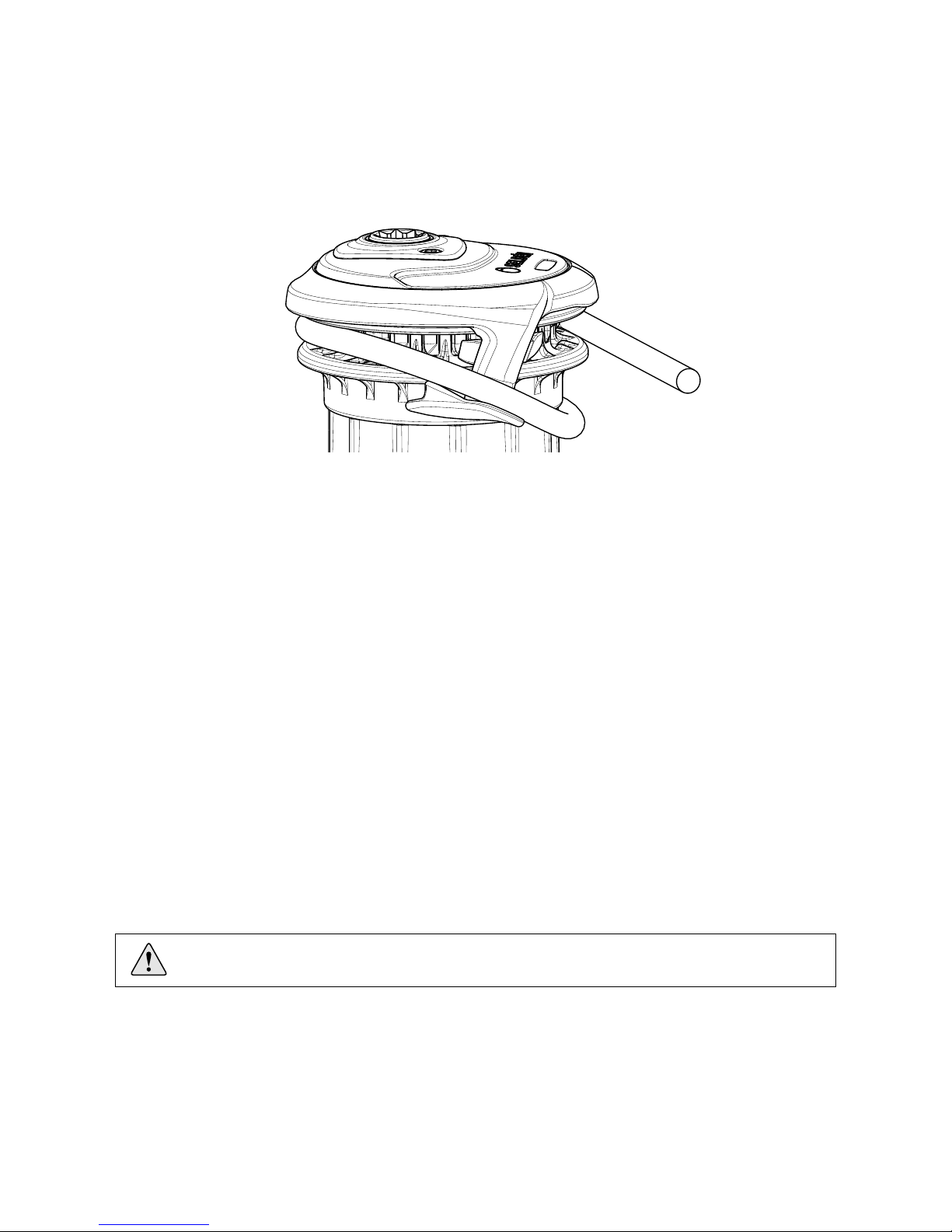
2. Lead the line over the self-tailing arm, into the self-tailing jaws for ¾ of a lap. The line remains in the selftailing jaws all the time during the winching operation.
3. Put the winch handle into the socket.
1. With the line, take 2-3 turns clockwise around the winch. The number of turns determines the grip and is
related to the line construction.
Fig. 2.a
Consider the risk of injury which is associated with winching! See chapter 1.3.
Due to the design of the self-tailing jaws it is also possible to pull the slack out of the sheet with the line sitting
in the self-tailing jaws and with the winch handle mounted. This means safer and quicker operation.
Page 8
8
3 Installation
3.1 Installation preparations
1. The winch should be mounted on a at surface. If not, any uneven surface must be compensated with shims.
2. Make sure the installation area is strong enough for the chosen size of winch.
3. The winch should not be mounted on any part of deck that is laminated using sandwich construction, such
as foam, etc.
4. If the winch is to be mounted on a surface of steel, bronze or brass, the base must be insulated against
galvanic corrosion. This is best done using a plastic insulator (0.5-1 mm) or sealant which covers the entire
contact area between the base and the mounting surface.
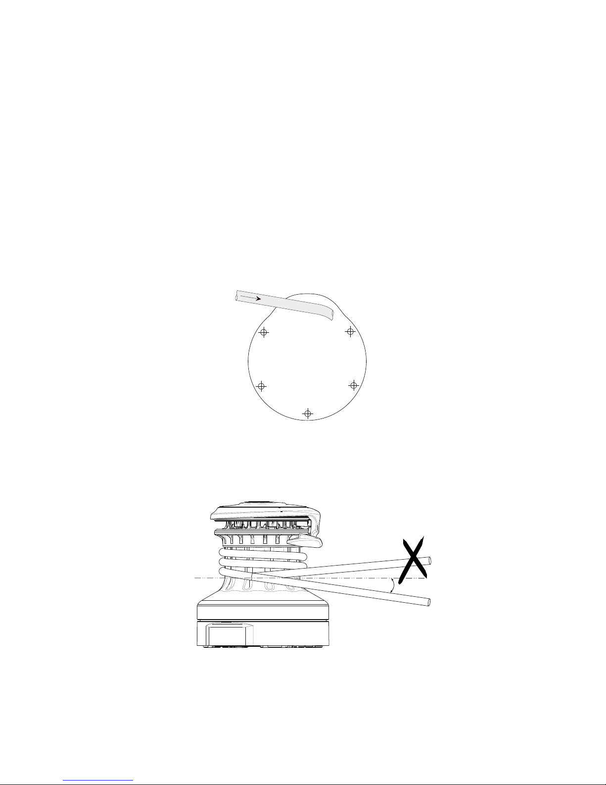
Decide the orientation of the winch according to operation direction, with reference to the mostly used line and
the bulb on the winch base. See g. 3.1.1.a or the drilling template, enclosed in the winch package.
The line should enter the winch according to g. 3.1.2.a to prevent from override.
3.1.1 Winching orientation
3.1.2 Line routing
Fig. 3.1.1.a
Fig. 3.1.2.a
Line entry position on Drum
for optimal performance
5-10º
Page 9

9
3.2 Installation instructions
The winch has two systems for installation:
1. Hexagon headed bolts which slides into a groove
in the winch base and where the hexagon heads
are locked against rotation due to the winch base
structure. No need to dismantle the winch. To
be used with washers and nuts below deck.See
chapter 3.2.1.
2. Hexagon socket head cap screw (Allen screws),
mounted from above. The winch needs to be
partly dismantled. E.g for cases where boats are
prepared with metal inserts in the deck construction. See chapter 3.2.2.
1. Cut the enclosed drill template to match the winches outline.
2. Place the template on deck at the desired position according to chapter 3.1.1 ”Winching orientation”
3. Drill the holes through deck using a drill according to the table below. We recommend predrilling with a
smaller drill for better accuracy.
3.2.1 Installation with hexagon headed bolts (sliding bolt system)
Winch Screw/Thread Drill for through
deck fastening
Drilling
template
S30
M6 Ø 7 mm 597-226-E
S40
S48
M8 Ø 9 mm 597-227-E
S54
Winch Hexagon headed
bolts
Hexagon socket
head cap screws
Cheese headed
screws
W D
max
S30 10 mm 10 mm Cheese headed
screws are
generally to large
in diameter to t.
S40
S48 13 mm 13 mm
S54
Fig. 3.2.1.a
Fig. 3.2.1.b
Countersunk recess
4. Cut the enclosed drill template to match the winches outline.
5. Place the template on deck at the desired position according to chapter 3.1.1 ”Winching orientation.
6. Drill the holes through deck using a drill according to table the table below. We recommend predrilling with
a smaller drill for better accuracy.
D
W
Page 10
10
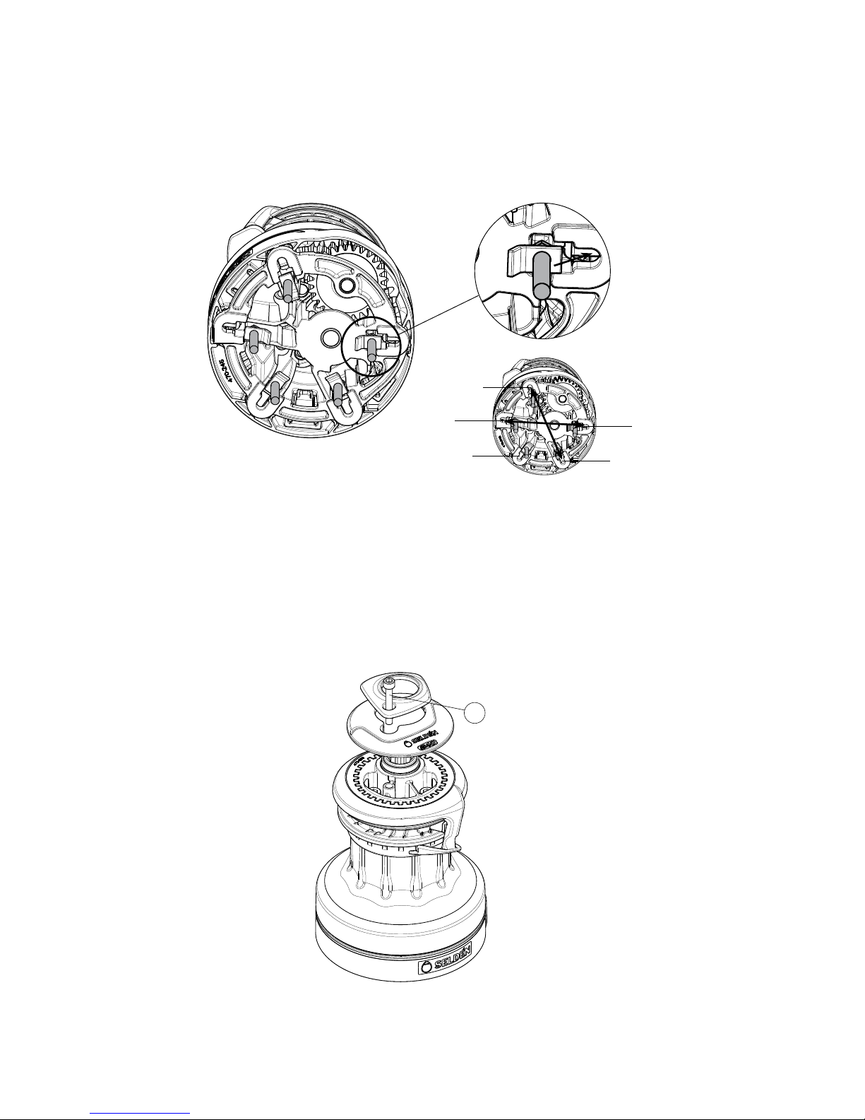
3.2.2 Adjustment of the self-tailing arm
Fig. 3.2.1.c
Fig. 3.2.2.a
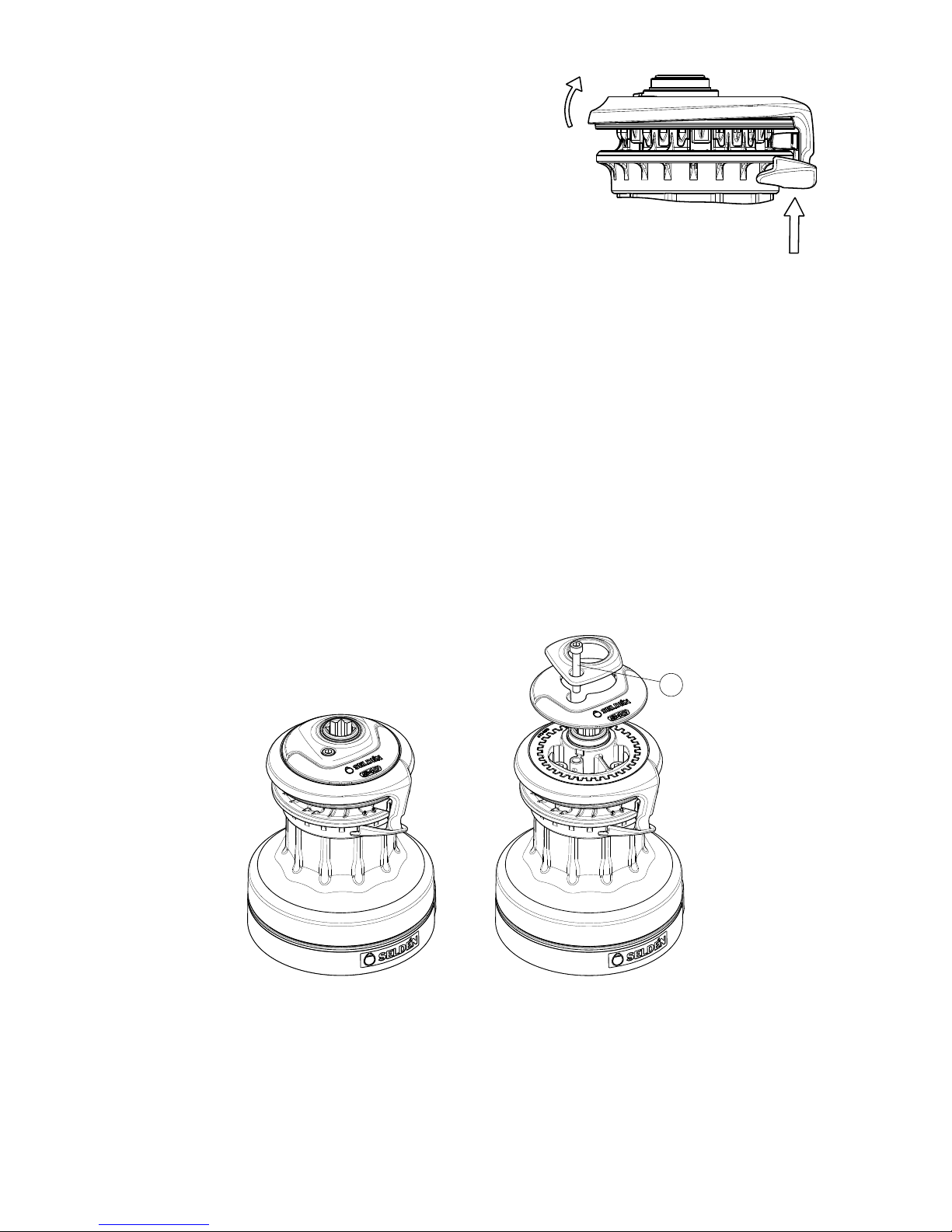
The direction of the Self-tailing arm may be adjusted. Preferably it should be mounted so that the line feeds into
the cockpit when using the winch.
Tools needed: Hexagon key 5 (M6).
1. Remove the cap screw (1), the top plate and the top cover.
7. Slide on an L-shaped washer onto each bolt according to g 3.2.1.b.
8. Mount the screw by sliding the hexagon head and the L-shaped washer into the base and apply sealant into
the U-recess and around the screw. Apply enough sealant to ll the entire cavity under the L-washer and the
countersunk recess at the holes in the deck.
9. Install the winch with the bolts into the deck simultaneously. Mount the washers and nuts below deck and
tighten opposite nuts from below, according to g. 3.2.1.c (bottom, right).
Crosswise tightening
1
Page 11
11
2. Push the Self tailing arm upwards while the opposite side of
the ring is lifted out of its position.
3. Turn it to the desired position.
4. Reassemble the parts in reverse order.
Fig. 3.2.2.b
Fig. 3.2.3.a
3.2.3 Installation with Hexagon socket head cap screw (Allen screws) with
cylindric head (None sliding bolt installation)
If the winch should be tted with Hexagon socket head cap screw (Allen screws), the winch must be partly
disassembled. This method of installation has to be used for threading into the deck, e.g. if the boat has purpose
made metal plates laminated into the deck structure or if non-hexagon headed through deck screws are used
with washer and nuts.
Tools needed for winch dismantling:
S30 & S40: Hexagon key 5 (M6), Hexagon key 6 (M8)
S48 & S54: Hexagon key 6 (M8), Hexagon key 8 (M10)
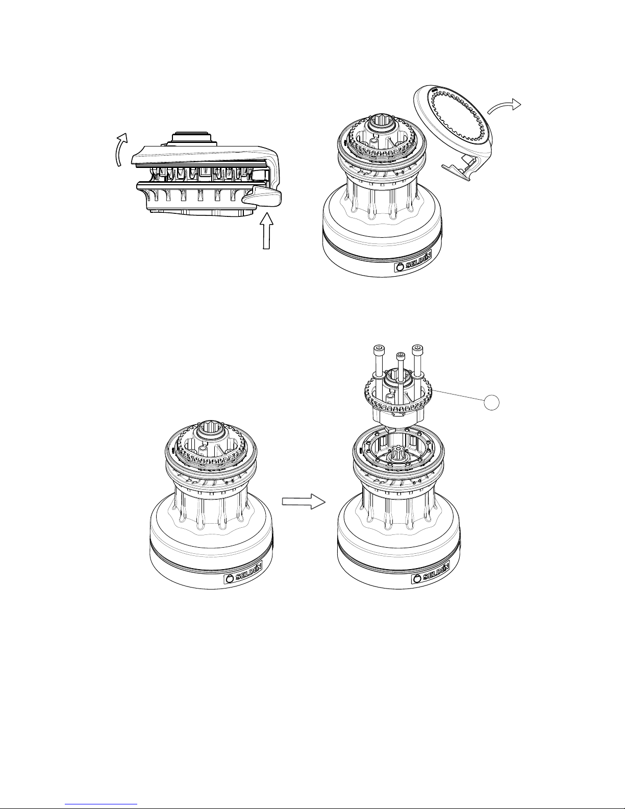
1. Remove the cap screw (1) on the top of the winch and remove the top plate and the top cover.
1
Page 12
12
Fig. 3.2.3.b
Fig. 3.2.3.c
2. Push the Self tailing arm upwards while the opposite side of the ring is lifted. Remove it.
3. Loosen the three screws which have now become visible. Remove the locator bracket (2).
2
Page 13
13
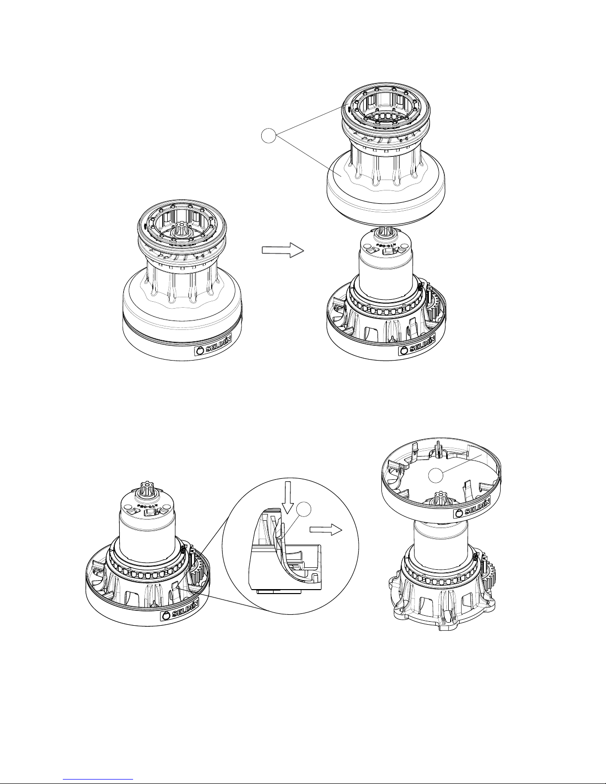
4. Lift the drum/self tailing jaws (3) together straight up. Make sure the composite hub remains on the base.
5. Loosen the clip (5) (x3) carefully from the base while lifting the base collar (4) and remove it.
Fig. 3.2.3.d
Fig. 3.2.3.e
4
5
3
Page 14
14
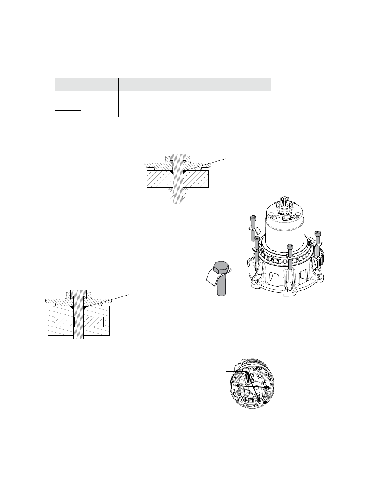
6. Mark the fastening holes using the winch base as a template or use the enclosed paper drilling template.
If the winch base is used as a template, use a smaller drill bit to mark the location of the hole.
If the paper drilling template is used, pre-drilling with a smaller drill (Ø 3-4 mm) is recommended for better
accuracy.
7. Drill either for through deck fastening or for threading in metal inserts.
8. Make a countersunk recess at the top of the holes. Along with the sealant, this recess will create aid sealing
around the bolt.
10. Reassemble the winch in reverse order of dismantling. Mount the self tailing arm so it guides the line into
the cockpit or preferred direction.
9.
Through deck fastening:
Slide an L-shaped washer onto each screw according to
g. 3.2.3.i. Mount the screws into the base and apply sealant
into the U-recess and around the screw. Apply enough sealant
to ll the countersunk recess at the hole in the deck.
Install the base and screws, in the deck simultaneously.
Mount the washer and nuts below deck. Hold the head of the
screw without turning it while the nuts are tightened opposite
nuts from below, according to g. 3.2.3.k.
Fastening by threading:
Apply sealant into the countersunk recess at the top of the
holes in deck. Make sure to get a full measure of sealant.
Position the winch over the holes. Slide on an L-shaped
washer on each screw according to g. 3.2.3.i. and t.
Tighten opposite screws is recommended, according to
g. 3.2.3.k.
Winch Screw/Thread Suitable size
for marking
Drill for through
deck fastening
Drill for thread in
metal inserts
Drilling
template
S30
M6 Ø 6 mm Ø 7 mm Ø 4.9 mm 597-226-E
S40
Tap M6
S48
M8 Ø 8 mm Ø 9 mm Ø 6.5 mm 597-227-E
S54
Tap M8
Fig. 3.2.3.g
Fig. 3.2.3.i
Fig. 3.2.3.h
Fig. 3.2.3.j
Fig. 3.2.3.k
Countersunk recess
Countersunk recess
Page 15
15
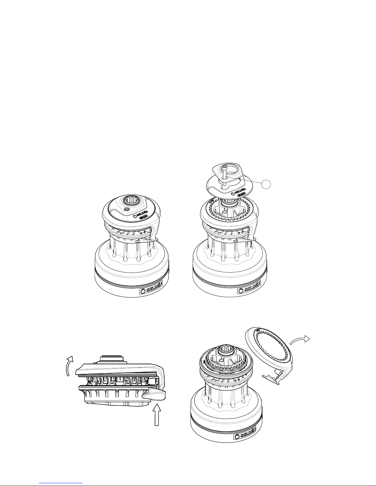
Fig. 4.1.a
4 Dismantling and maintenance
4.1 Dismantling for normal service
To obtain full function and performance of the winch it is important that these maintenance instructions are
followed carefully. Grease should be applied ONLY at these places where stated.
During dismantling, check wear and condition of all parts. Replace if necessary.
Tools needed:
S30 & S40: Hexagon key 5 (M6), Hexagon key 6 (M8)
S48 & S54: Hexagon key 6 (M8), Hexagon key 8 (M10)
1. Remove the cap screw (1) and remove the top plate and the top cover.
Fig. 4.1.b
2. Push the Self tailing arm upwards while the opposite side of the ring is lifted. Remove it.
1
Page 16
16
Fig. 4.1.c
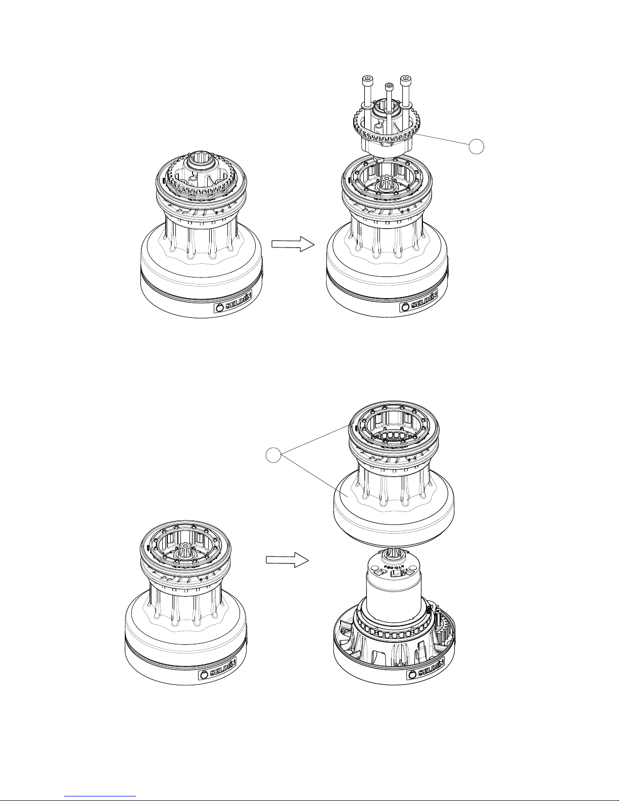
3. Loosen the three screws which now has become visible. Remove the locator bracket (2).
4. Lift the drum/self tailing jaws (3) together straight up. Make sure the composite hub remains on the base.
Fig. 4.1.d
2
3
Page 17
17
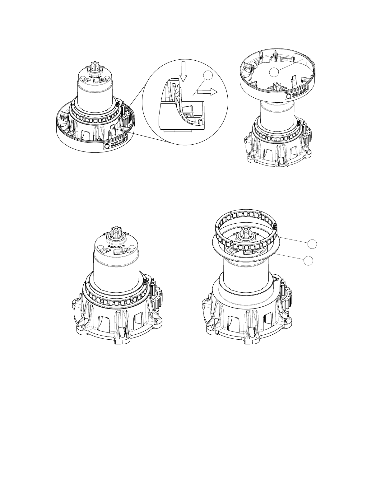
5. Loosen the clip (5) (x3) carefully from the base while lifting the base collar (4) and remove it.
6. Remove the lower roller bearing (6) and the washer (7).
7. Perform service according to chapter 4.3 “Service Instructions”.
8. Reassemble the winch in reverse order of dismantling. Mount the self tailing arm so it guides the line into
the cockpit or preferred direction.
Fig. 4.1.e
Fig. 4.1.f
6
7
5
4
Page 18
18
4.2 Dismantling for extended service
Continuation of the dismantling according to chapter 4.1 “Dismantling for normal service”, steps 1-6.
Keep careful track of the order in which the parts are dismantled.
Reassemble sub-assemblies directly after checking and cleaning if possible.
Handle all parts carefully. Place the disassembled parts on soft cloths or similar.
Tools needed:
Small-medium sized at screwdriver
Needle nose pliers
Hexagon key 5 (M6)
Fig. 4.2.a
Fig. 4.2.b Fig. 4.2.c
Fig. 4.2.e Fig. 4.2.d
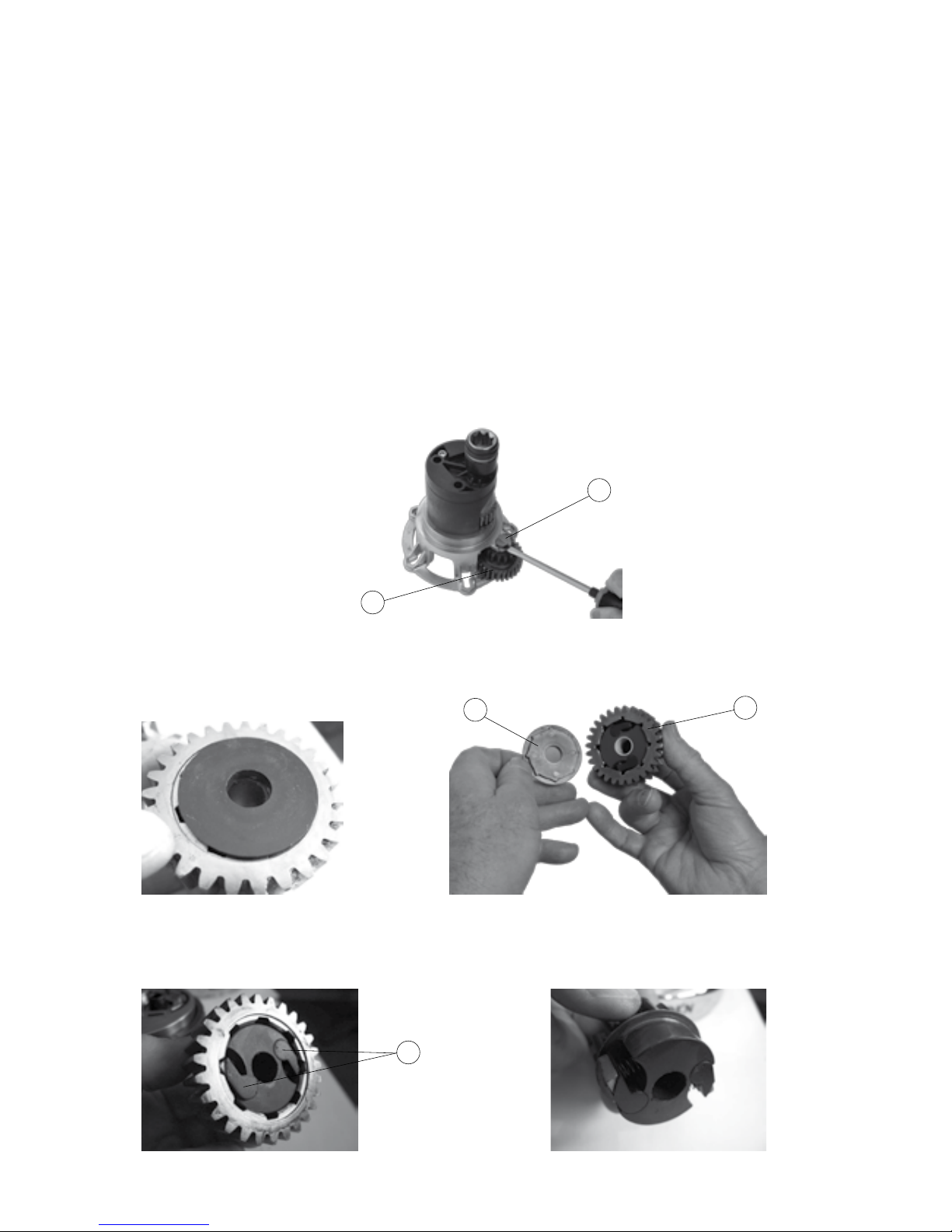
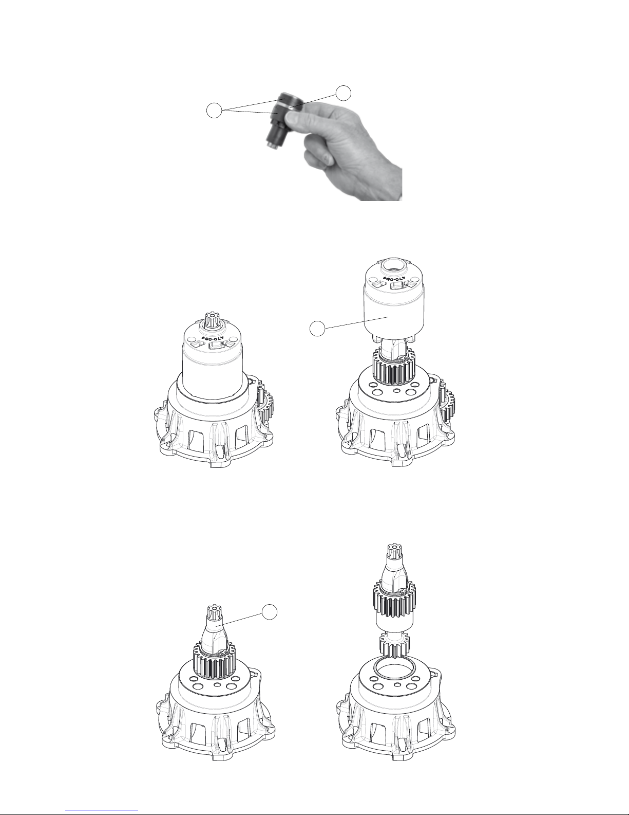
3. Pull off the ratchet wheel and check functionality of the pawls (12). Dismantle the pawls and pawl springs if
necessary. Worn pawls and springs should be replaced.
2. Remove the washer (10). Note how this washer and ratchet wheel (11) are mounted. The washer has an
asymmetrical rear and t only to the ratchet wheel if this is tted in the correct direction.
1. Remove the shaft (8) and the twin cog wheel (9).
8
9
11
10
12
Page 19
19
Fig. 4.2.f
Fig. 4.2.g
Fig. 4.2.h
4. Lift out the winch handle socket (13) together with its bushings (14).
5. Remove the hub (16) from the base.
6. Remove the drive shaft (17) from the base by lifting it straight up.
13
14
17
16
Page 20
20
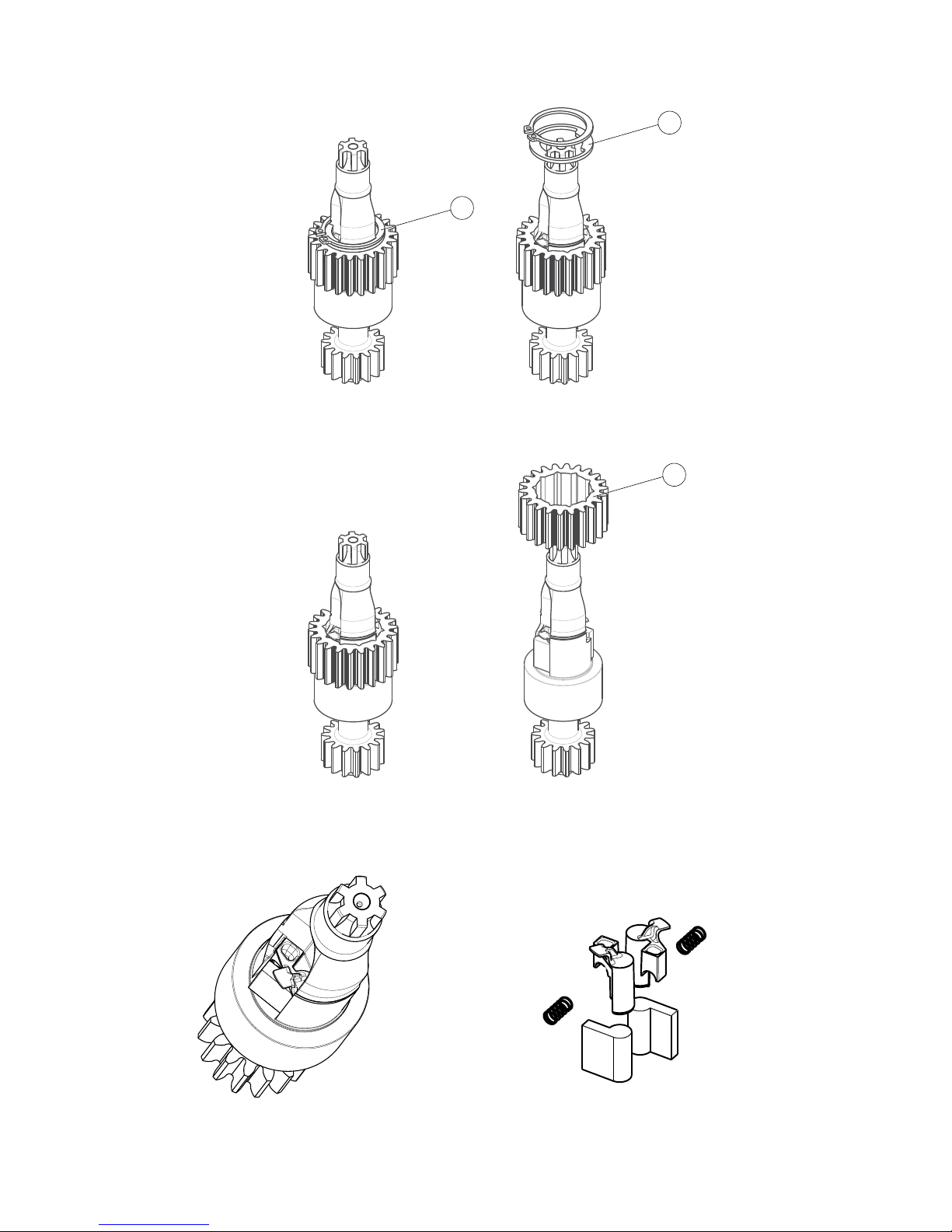
7. Remove the circlip (18) and the washer (19) from the drive shaft.
8. To dismantle the pawls and pawl springs remove the gear wheel (20).
9. Check functionality of the pawls. Dismantle the pawls and pawl springs if necessary. Clean the parts to
ensure full function. Worn pawls and springs should be replaced.
10. Reassemble the winch in reverse order of dismantling. Adjust the self tailing arm so it guides the line into
the cockpit or preferred direction.
Fig. 4.2.i
Fig. 4.2.j
Fig. 4.2.k
Fig. 4.2.l
18
19
20
Page 21
21
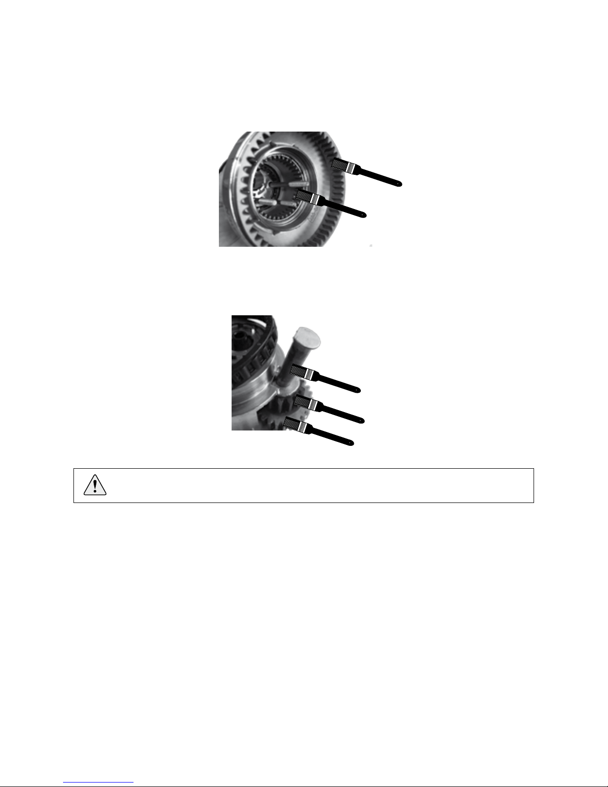
Fig. 4.3.a
Fig. 4.3.b
4.3 Service instructions
1. Dismantle the winch according to the steps 4.1.
2. Clean all surfaces before lubricating using a dry cloth or white spirit.
3. Apply a thin layer of grease with a brush at the upper and lower gear ring in the drum.
Use Seldén lubrication grease art.no: 312-501.
4. Lift the shaft which holds the twin gear wheel and lubricate the shaft. Put it back. Lubricate the geat teeth at
the twin gear wheel.
Any grease should be applied ONLY at these places where it is stated.
Page 22

22
Notes
Page 23

23
Notes
Page 24

24
Seldén Mast AB, Sweden
Tel +46 (0)31 69 69 00
Fax +46 (0)31 29 71 37
e-mail [email protected]
Seldén Mast Limited, UK
Tel +44 (0) 1329 504000
Fax +44 (0) 1329 504049
e-mail [email protected]
Seldén Mast Inc., USA
Tel +1 843-760-6278
Fax +1 843-760-1220
e-mail [email protected]
Seldén Mast A/S, DK
Tel +45 39 18 44 00
Fax +45 39 27 17 00
e-mail [email protected]
Seldén Mid Europe B.V., NL
Tel +31 (0) 111-698 120
Fax +31 (0) 111-698 130
e-mail [email protected]
Seldén Mast SAS, FR
Tel +33 (0) 251 362 110
Fax +33 (0) 251 362 185
e-mail [email protected]
Seldén Mast Asia Ltd,
Hong Kong
Tel +852 3572 0613
Fax +852 3572 0623
e-mail [email protected]
www.seldenmast.com
Dealer:
DINGHIESKEELBOATSYACHTS
The Seldén Group is the world’s leading manu-
facturer of mast and rigging systems in carbon and
aluminium for dinghies, keelboats and yachts.
Our well known brands are Seldén and Furlex.
The worldwide success of Furlex has enabled us to
build a network of over 750 authorised dealers
covering the world’s marine markets. So wherever
you sail, you can be sure of fast access to our
service, spare parts and know-how.
SELDÉN and FURLEX are registered trademarks of Seldén Mast AB
597-225-E Printed in Sweden
 Loading...