


NONLINEAR JUNCTION DETECTOR
ST 400 (402)
‘CAYMAN’
OPERATING MANUAL
English

OPERATING MANUAL
22
CONTENTS
pg.
1. Description 23
1.1. Purpose 23
1.2. Delivery package 23
1.3. Main Technical Specications 24
1.4. Principles of Operation 24
1.5. Operation Modes 25
1.6. Structure 25
1.6.1. Antenna Module 26
1.6.2. Main Unit 27
1.6.3. Telescopic Arm 27
1.6.4. Controls 28
2. Use 28
2.1. Preparation 28
2.2. Adaptive Mode 29
2.3. Operational check with test dummies 30
2.4. SEARCH Mode 30
2.5. Listening (Audio Mode) 32
2.6. Program Updates 34
3. Electric Power Supply 35
4. Operating Restrictions 35
5. Storage and Transportation 36
6. Warranty 36

ST 402 ‘CAYMAN’ NLJD
23
This operating manual contains important technical information and guidance on proper use
of the product. Please read the manual before using ST 402 Cayman.
1. Description
1.1. Purpose
ST 400 Cayman is intended to detect and locate
• eavesdropping electronics
• mobile phones and SIM cards
• any other devices utilising semiconductor technology
ST 402 Cayman allows detecting electronic devices, whether active or not, as well as
finding their exact location. It also enables one to distinguish between return signals from real
semiconductors and other kinds of responses, such as those given by corrosion or metal-oxidemetal structures.
1.2. Delivery package
ST 400 Cayman comes in a shockproof case that contains the following.
*The electric charger and headphones are lodged at the bottom, underneath the device.
Item Quantity No. in Fig. 1
ST 40
2 ‘Cayman’ NLJD 1 2
Accumulator Battery (type 18650) 2 3
Charger Power Adapter 1 4
Electric Charger 1 5*
Headphones 1 6*
Semiconductor Imitating Dummy (marked red) 1 1
MOM-Structure Imitating Dummy (marked blue) 1 1
Operating Manual 1 not shown in g.
Case 1 not shown in g.
Fig. 1

1.3. Main Technical Specications
Range of radiated frequencies 2–3GHz
Max. peak radiated power < 2W
Antenna polarisation elliptic
Operation modes SEARCH
AUDIO
ADAPT
Sensitivity range in manual mode 40dB (5 values with 8dB increment)
Response indication
– visual three 16-segment LED gauge bars
– aural internal speaker or headphones
Power supply two 3.7V rechargeable Li-ion batteries
(type 18650)
Time of operation on one battery charge 3-4 hours, depending on the operation mode
Battery charging time < 3 hours
Operating conditions
– working temperature range +5...+40°С
– relative air humidity up to 85 percent (at 25°С)
Weight (with batteries) 1,75kg
Dimensions (length×width×height)
– when folded
510х145х130mm
– with telescopic arm pulled out completely
1500х250х130mm
Weight of full set in case 5,8kg
1.4. Principles of Operation
ST 40
2 Cayman is a nonlinear junction detector, or NLJD. Instruments of this type employ
active detection, i.e. they emit probing signals and analyse the return. Their primary search targets
are electronic devices, and those typically consist of circuit plates with conductive elements and
various semiconductor parts connected to them, such as diodes, transistors, and microchips.
The probing electromagnetic radiation induces variable electromotive forces in these loops, and
electronic components with a non-linear current-voltage curve transform the initial signal into its
higher frequency harmonics, which come back to the NLJD’s receiver.
Higher harmonics can also be re-radiated by corroded metal or the so-called MOM-diodes,
metal-oxide-metal structures brought about by contacting metal surfaces. However, these
formations return somewhat different spectra than semiconductors.
With ST 40
2 Cayman one can distinguish with high probability between responses given by
real semiconductors, and those ‘faked’ by MOM-structures or corrosion. Another important
advantage is a condent detection of search targets behind partially shielding obstacles, which is
achieved by simultaneously radiating several frequencies within the 2-3GHz band and analysing
the composite picture of the reection spectrum.
OPERATING MANUAL
24
1.5. Operation Modes
The NLJD ST 40
2 Cayman has the following modes of operation:
Primary operation mode: SEARCH
Secondary operation mode: AUDIO
Service mode: ADAPT
The main operation mode named SEARCH is meant for detecting nonlinear targets and
identifying them, based on the response levels as indicated by 16-segment bars.
The auxiliary operation mode named AUDIO allows demodulating the response and listening
to it through the built-in speaker or headphones. Use this mode upon detecting a response in the
SEARCH mode.
The ADAPT service mode is used to optimise the parameters in a given electromagnetic
environment and thus maximise the effectiveness of search. Engaging this mode is necessary
every time the device is switched on. It is advisable to pause during searches from time to time,
to repeat this procedure. During adaptation, the antenna must be pointed away from electronics
and large metal objects.
1.6. Structure
Structurally, the ST 402 Cayman NLJD consists of the main unit and antenna module, that
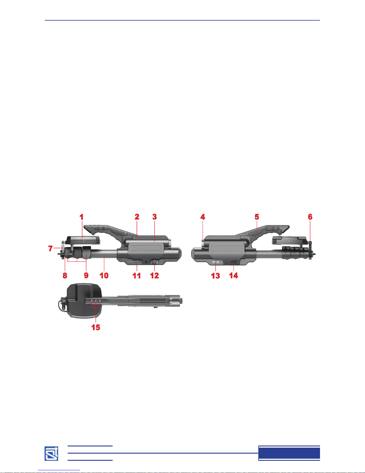
are connected with a telescopic arm. The main constituents are shown in Fig. 2.
The numbers in Fig. 2 stand for:
1 – antenna module
2 – main unit
3 – battery compartment
4 – battery compartment cap
5 – handle
6 – antenna module bracket
7 – lever handle of the clamp
8 – power-and-control cable with plug
9 – cam clamps of the telescopic arm
10 – telescopic arm
Fig. 2
11 – headphone socket
12 – power and volume knob
13 – ID plate
14 – inbuilt speaker
15 – controls
ST 402 ‘CAYMAN’ NLJD
25

OPERATING MANUAL
26
1.6.1. Antenna module
The antenna module comprises a receivertransmitter unit, a control-display unit, and an aerial,
all of which are assembled on a single platform
and incorporated in a single body. The antenna is
mounted at the end of a telescopic arm by way of a
hinge joint that allows adjusting the incline within
the vertical plane along the rod’s axis, as shown in
Fig. 3. To change the incline, unlock the clamp by
turning its handle counter-clockwise, as shown in
Fig. 3, then adjust and lock by turning the clamp
handle in the clockwise direction.
Fig. 3
Do not try to change the antenna incline with the clamp locked: you may break the hinge
joint!
Fig. 4
On the antenna surface facing the operator, there are an indicator panel, a socket for the
power-and-control cable, and a USB port for computer connection (Fig. 4).
The numbers in Fig. 4 stand for the following:
# in Fig. 4 description colour subscript on
indicator panel
1 16-segment led gauge of threat-type response
levels
red 1
2 16-segment led gauge of MOM-type
response levels
blue 2

ST 402 ‘CAYMAN’ NLJD
27
3 16-segment led gauge of reection levels white 3
4 Power-on led indicator red POWER
5 SEARCH mode indicator yellow SEARCH
6 AUDIO mode indicator yellow AUDIO
7 5-segment tuning bar* yellow TUNING
8 socket for power-and-control cable CONTROL
9 USB port USB
* the TUNING segment bar has two functions:
– in the SEARCH mode, it shows the selected sensitivity of the receiver (SEN)
– in the AUDIO mode, it shows the selected frequency combination (CH 1..5)
The boresight directions of the receiving and transmitting antennas are shown in Fig. 5.
Fig. 5
1.6.2. Main Unit
The main unit of ST 40
2 Cayman is housed in a durable plastic body (2, Fig. 2) fitted on top
with a handle (5, Fig. 2) with three control buttons (15, Fig. 2). It has a battery compartment (3,
Fig. 2) for two type 18650 accumulator batteries, closed with a metal cap (4, Fig. 2). On the left
side of the main unit are a headphone socket (11, Fig. 2) and a power-and-volume knob (12,
Fig.2), and on the right side there is a shield bearing the name of the device, its serial number,
and the name of its manufacturer company (13, Fig. 2). Also on the right, a speaker grid can be
found (14, Fig. 2).
The main unit’s body hosts electronics controlling the device. For durability’s sake, all the
components of the main unit are assembled on a single bearing structure made of metal, while the
plastic body only serves protective and aesthetic purposes.
1.6.3. Telescopic Arm
The four-section telescopic arm is used to bring the antenna up close to remote objects under
inspection. Its length can be adjusted with the aid of cam clamps (9, Fig. 2).
Its base section is anchored inside the main unit. The fore section of the rod is tted with
a bracket mount for the antenna module (6, Fig. 2). A lever handle (7, Fig. 2) is used to x the
antenna in a desired position.

OPERATING MANUAL
28
A twisted cable goes through the arm, connecting the antenna with the power and control
units housed in the main body. Fig. 6 shows the device with the arm retracted, and fully extended.
Fig. 6
1.6.4. Controls
Three control buttons are at the front of the handle (Fig. 7).
The mode-setting button (2, Fig. 7) is marked with an
.
A short press of this button alternates between SEARCH
and AUDIO; holding it down for a few seconds will set the
device to the ADAPT mode.
The other two buttons marked and (1 and 3, Fig. 7)
are for tuning the device. Depending on the mode, they allow:
– in the SEARCH mode, increasing and decreasing the receiver
sensitivity, respectively.
– in the AUDIO mode, setting the desired frequency
combination.
Fig. 7
2. USE
2.1. Preparation
Take the device and rechargeable batteries out of the case. Examine the main unit, antenna, cable
and socket for mechanical damage. Examine the batteries for mechanical damage and electrode
corrosion. Do not use the device if any such defects are found!
To replace the batteries, do the following:
• unscrew the battery compartment cap;
• insert two accumulator batteries as shown in Fig. 8, making sure you observe the polarity;
• screw the cap back in place.

ST 402 ‘CAYMAN’ NLJD
29
Make sure the power switch (12, Fig. 2) is in the leftmost position (off). Connect the power-andcontrol cable plug (8, Fig. 2) to the socket on antenna module (8, Fig. 4). Switch on the device by
turning the knob clockwise; the device status will be displayed on the antenna module as shown
in Table 1 below.
Table 1
Fig. 8
legend colour light indication interpretation
POWER red continuous The antenna module is powered
properly.
blinking The battery is discharged and needs
to be replaced.
TUNING
SEN
yellow continuous This displays receiver gain. At
startup the gain is automatically set
to maximum, which is signalled by
all the 5 indicator segments being lit.
SEARCH yellow continuous This displays the operating mode.
The SEARCH mode is selected
automatically at startup.
Upon activation of the device one or more LEDs of the signal level gauge bars (1–3, Fig. 4)
may light and go out spontaneously. This would mean that the device should need to be adjusted
to the electromagnetic environment using the adaptive mode.
2.2. Adaptive mode
To activate this mode, press and hold for 3-4 sec the MODE button (2, Fig. 7) on the main unit
control panel. The antenna must be directed away from large metal objects and anything that is
presumed to contain nonlinear elements (it is often best to point the antenna at either the oor or
ceiling).
The adaptation takes 10–15 seconds, with all the indicators but TUNING lit in the meantime on
the antenna module. The TUNING indicator will be showing a consecutive lighting of segments.
Meanwhile, the user can check if any of the indicator LEDs are dead.
Upon adaptation the device status will be displayed in accordance with Table 1.

OPERATING MANUAL
30
2.3. Operational check with test dummies
Once ST 40
2 Cayman has been adapted to the environment, its functioning should be checked
with the aid of test dummies that imitate nonlinear materials (1, Fig. 1).
For that purpose select an area free of responses from nonlinear elements or reecting
surfaces, and place there the dummy that is marked red.
Press button
(3, Fig. 7) repeatedly to set the receiver gain at 3 lit segments of the
TUNING indicator, which corresponds to medium sensitivity.
Point the antenna at the test dummy and nd the distance at which all the 16 segments of the
INPUT LEVEL Gauge bar 1 light up. For a device that is in proper working order and has selftuned properly, this distance should be no less than 0.8 m.
Repeat the procedure using the dummy with the blue marking. In doing so, nd the distance
at which all the segments of the INPUT LEVEL gauge bar 2 will be lit. For a properly working
device that has been adjusted to the environment, this distance should be no less than 0.3m.
If either distance is found to be smaller than the respective value above, it is advisable to
engage the self-tuning routine anew (see 2.2) and repeat the checks as described above.
If both distances exceed the required minimums, the device is functional and operation-ready.
2.4. SEARCH Mode
Once ST 402 Cayman has been prepared and proven functional as described above in 2.1 –
2.3, it can be put to use. When activated, the device starts up in SEARCH mode, and the receiver
gain is by default set to maximum, which is displayed by 5 lit segments of the TUNING indicator.
The SEARCH mode is the primary operation mode for ST 400. The operator can change the
receiver gain at his discretion, thus increasing or decreasing the detection range.
The gain can be varied discretely with an 8dB increment, over 5 values in a 40dB range; each
increment corresponds to one LED segment of the TUNING indicator. Thus, if all ve are lit, the
gain is equal to 40dB, providing maximum detection range. If all are dimmed, the gain is 0dB,
with minimum detection range. The gain can be brought a step up or down by a single pressing of
the TUNING buttons
or (1 and 3, Fig. 7).
Levels of return signals from a target area are shown in the three INPUT LEVEL multisegment LED gauge bars (Fig. 4: 4–6).
INPUT LEVEL led gauge bar 1 (16 red LEDs) displays the levels of return signals from
semiconductor material. The indication is accompanied with an alternating sound alarm.
INPUT LEVEL led gauge bar 2 (16 blue LEDs) displays the levels of return signals from
MOM (metal/oxide/metal) structures.
INPUT LEVEL led gauge bar 3 (16 white LEDs) displays the levels of return signals from
reecting surfaces (most likely, metal).
The greater the response of a certain type, the more LEDs will light up in the corresponding
INPUT LEVEL gauge bar.
Recommendations
With an NLJD one typically probes
• enclosing structures (walls, ceilings, oors)
• different parts of the interior
• various objects that are not supposed to contain semiconductor material

ST 402 ‘CAYMAN’ NLJD
31
Items known to contain semiconductor components (electronic instruments, ofce and home
equipment, communication devices, etc.) are checked by other means.
When running checks on enclosing structures, it is important to set a suitable receiver gain. If
excessive, it may well cause detection of objects behind the walls, which may be a problem when
there is no access into the adjoining spaces. On the other hand, if the gain is too small, targets of
interest with a weak response may remain undiscovered in the structure under scrutiny.
While scanning walls and other large vertical structures, it is recommendable to move the
antenna from top to bottom in a serpentine fashion, as is shown in Fig. 9.
Fig. 9
The antenna head should be held at a distance of 5-15 cm from the surface.
If a potent response is registered (all LEDs in an multi-segment LED gauge bar light up), the
gain should be decreased in order to establish the exact location of the responding target.
The primary task for an NLJD is the discovery of eavesdropping devices, whose giveaways
are the signals returned by semiconductor-containing electronic components and by MOMstructures on casings, at junctures, etc. Therefore, particular attention should be paid to scanned
areas where responses have been observed on the red led gauge bar alone, and on both red and
blue multi-segment LED gauge bars. The nature of each such response should be determined and
its source identied.
A strong, off-scale response on one of the multi-segment LED gauge bars may be accompanied
by a much weaker one on another. As a rule, the former is a true response and the latter a false
one; it is advisable to decrease the gain or move away from the target until there is no off-scaling.
Small-sized objects should be checked at locations where no response is observed on any of
the three INPUT LEVEL led gauge bars, preferably away from large metal structures, pillars,
cabinets, safes, etc.

OPERATING MANUAL
32
2.5. Listening (AUDIO mode)
The AUDIO mode is primarily intended for analysing target responses by listening to the
demodulated signal output. This should give the operator ample information to identify the
response type.
To switch from SEARCH to AUDIO, press
. The SEARCH led (5, Fig. 4) on the antenna
head will then go off, and AUDIO led will light up (6, Fig. 4).
When the AUDIO mode is on, the device status will be displayed on the antenna module as
described in Table 2 below.
Table 2
*Upon switching to AUDIO, none of the TUNING bar segments are lit, which corresponds
to #0 frequency combination.
The ST 402 Cayman NLJD makes it possible to listen to demodulated signals while probing
with six different frequency combinations. Each combination, indicated by LEDs on the TUNING
bar, is suited to deal with a particular category of nonlinear objects. Upon activation of the AUDIO
mode, frequency combination #0 is set by default; it is meant for probing semiconductor content
and, as a rule, gives good results in identifying active radio-transmitting and sound-recording
devices.
Frequency combination #1 is used to analyse return signals from MOM (metal/oxide/metal)
structures.
The remaining four combinations are auxiliary. Their use is advised when responses have been
observed in the SEARCH mode on the red INPUT LEVEL bar, yet probing with combination #0
has rendered no denitive ndings.
Table 3 shows correspondence between frequency combinations and responses observed in
the SEARCH mode.
legend colour light indication meaning
POWER red continuous The antenna module is powered properly.
blinking The battery is discharged and needs to be
replaced.
TUNING yellow continuous* The 5-segment bar displays the selected
probing frequency combination.
AUDIO yellow continuous AUDIO mode on.
INPUT
LEVEL 3
white varying numbers of
lit LEDs
The 16-segment bar displays the levels
of returned signals. Note: in the AUDIO
mode this gauge bar shows a sum total of
responses, regardless of their type.

ST 402 ‘CAYMAN’ NLJD
33
Table 3
indication on TUNING bar
freq. combination #
0 1 2 3 4 5
gauge bar # in SEARCH mode
1 2 1 1 1 1
Use buttons and to change probing frequency combinations (1 and 3, Fig.7).
Table 4 shows typical results of analysing targets with nonlinear properties.
Table 4
Type of probed
target
Optimum frequency
combination
Sounds when
subjected to
mechanical impact
or test sound
Sounds in the
absence of
mechanical impact
or test sound
MOM-structure 1 crackling, creaking none
active electronic
devices (unencoded
transmission channel)
0 (2–5) audible response to
tapping or test sound
sounds of the
environment
active electronic
devices (encoded
transmission channel)
0 (2–5) peculiar signals
caused by the
operation of
the device and
independent of
sounds in the
environment
peculiar signals
caused by the
operation of
the device and
independent of
sounds in the
environment
inactive electronic
devices
0 (2–5) none none
active electromechanic or
mechanic appliances
0-5 crackling, creaking peculiar signals
caused by the
operation of
the device and
independent of
sounds in the
environment

OPERATING MANUAL
34
When listening to demodulated signals, it is recommended to use headphones. Sound volume
is adjustable with a variable resistor (12, Fig. 2).
Recommendations
Any response observed on the red bar (or on both red and blue bar simultaneously) should be
analysed in the audio mode with the use of a test sound source. If a response has been observed
on the blue bar, it is advisable to perform audio analysis with the frequency combination #1,
subjecting the target area to mechanical impact (tapping). While probing, it is advisable to change
gradually the distance between the antenna and target within 5–100 cm range.
Push M to switch from the AUDIO mode to SEARCH.
2.6. Program Updates
ST400 Cayman has a processor that operates in accordance with the program rmware that
is pre-installed by the manufacturer company. Over time the rmware gets rened and newer
versions get released, that can be installed through the USB port.
‘What is my rmware version?’
In order to nd out what rmware version is currently installed on your ST400, set it to
SEARCH, then press
and hold it for 3 seconds. The three INPUT LEVEL bars (4, 5 and
6, Fig. 4) will light up, with the number of lit LEDs indicating the current version in the format
‘R.B.W’ (red, blue, and white). For example, if 1 red, 2 blue, and 5 white LEDs are lit up, then
the current version is 1.2.5.
Press any button to exit this mode.
Firmware update procedure
The newest firmware version, with issues sorted out or features added, can be downloaded
from http://spymarket.com/ (‘ST 402 CAYMAN’ section) and installed through the USB port
with the installer enclosed with the update les.
In order to update the ST 40
2 Cayman firmware, do the following:
– turn off the device (if activated)
– using a thin object, open the USB socket cover on the antenna panel (9, Fig. 4)
–
connect ST402
Cayman to the computer using a USB cable
– turn on the device
– when the POWER led (4, Fig. 4) lights up, within 5 seconds briey press
; after 5
seconds the power-on LED will go dim to indicate that the device is now in the updating mode
– turn off the device
– follow instructions in the README le that comes with the update.
WARNING! Once the updating process has started, ST 400 Cayman can only be switched
into operation again upon completion of the update installation.

ST 402 ‘CAYMAN’ NLJD
35
3. POWER SUPPLY
ST 40
2 Cayman is powered by two Li-ion rechargeable batteries (type 18650). 4 batteries
are included in the delivery package. The total run time on one battery charge is from 3 to 4
hours, depending on the modes employed; the most demanding in terms of power consumption
is the AUDIO mode.
The batteries are housed in the battery compartment at the back of the main unit. Battery
replacement is described in 2.1 above.
ST 40
2 Cayman monitors its battery charge status. A continuously lit power-on led (4, Fig.
4) on the antenna head means that the battery charge is sufcient. A low battery charge will be
signalled by blinking of the power-on LED and a warning sound. If the charge goes below the
critical threshold, the device will switch off automatically.
Accumulator batteries can be charged with the charger included in the delivery package. The
charging time of a fully discharged battery is 3 hours. As these batteries are free of memory effect,
incomplete charging is acceptable, but the running time will then be shorter.
The following is not allowed:
– long-term storage of discharged batteries
– long-term storage of batteries at low temperatures
– short-circuiting battery contacts
– subjecting batteries to strong shock
– transportation of the device with an installed battery.
4. OPERATING RESTRICTIONS
Use of the device is subject to safety regulations for equipment incorporating UHF
transmitters. The following must be observed at all times:
• Avoid long exposure of people to the antenna beam (the main lobe of the polar diagram) at
distances less than 1m.
• Do not point the antenna at people’s eyes at distances less than 1m.
If the device has been transported at temperatures well outside the service temperature range,
make sure to keep the device indoors at service temperature for 2 hours before use.

OPERATING MANUAL
36
5. STORAGE AND TRANSPORTATION
The device must be stored in heated storage facilities pursuant to GOST V9.003–80 (ГОСТ
В9.003–80). The following conditions must be maintained:
1) ambient temperatures from + 0 to 50°С;
2) relative air humidity 80 percent at 30°С;
3) atmospheric pressure from 630 to 820 mmHg;
4) absence of acidic, alkaline, or other aggressive vapours.
The device can be transported in standard packaging by any suitable means of conveyance
(in a pressurised module, if transported by plane) as long as it is protected from atmospheric
moisture. While transporting the device, avoid dropping or otherwise subjecting it to strong
impacts. During transportation, the mechanical conditions must comply with medium level
requirements per GOST В20.57.310–76, while the ambient conditions must correspond to those
specied by GOST В9.003–80 for open-air storage.
6. WARRANTY
The manufacturer guarantees compliance of every manufactured item with all the requirements
as per technical specications, within 12 months of the date of purchase.
During the warranty period, the manufacturer guarantees free of charge repairs of the device,
its auxiliary components and accessories, up to full replacement.
Free repairs or replacement can only be claimed if the user has observed all the rules of
operation, transportation, and storage of the device, and on condition that the device itself and
its ancillary parts are free from mechanical damage, and upon submission of a properly lled out
warranty coupon.
Upon expiry of the warranty period, post-warranty servicing is available from the manufacturer.
The warranty does not cover batteries.
 Loading...