

Page 1

DS7060 User Guide Copyright © 1996-97 Detection Systems, Inc.
User Guide
for the
DS7060 Control/Communicator
Copyright © 1996-97 Detection Systems, Inc.
Detection Systems, Inc., 130 Perinton Parkway, Fairport, New York, USA 14450 -9199
(716) 223-4060 • (800) 289-0096 • Fax: (716) 223-9180
DS7060 User Guide P/N 29955C
Page 2

Table of Contents
1.1 Understanding the DS7443, DS7445, and DS7447 Keypads......................................... 4
1.2 P ersonal Identification Numbers .................................................................................... 6
1.3 Turning ON (arming) the System ................................................................................... 8
1.4 Quick Arming the System ............................................................................................ 10
1.5 Easy Exit ..................................................................................................................... 10
1.6 Turning OFF (disarming) the System/Silencing Alarms ............................................... 10
1.7 Force Arming ............................................................................................................... 12
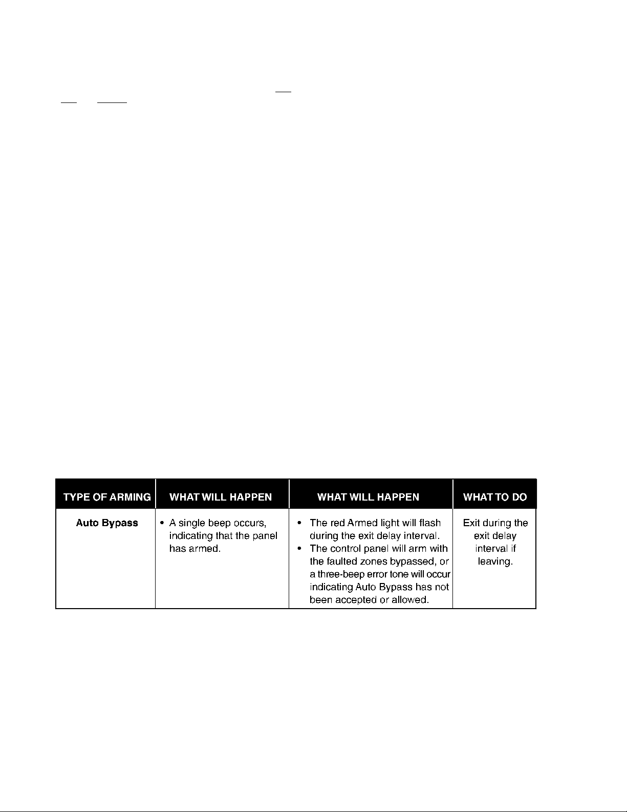
1.8 Auto Bypass ................................................................................................................ 13
1.9 Zone Bypass ............................................................................................................... 13
1.10 Chime Mode ................................................................................................................ 15
1.11 Zone Test..................................................................................................................... 15
1.12 Local Battery/Sounder Test.......................................................................................... 17
1.13 Communicator T est...................................................................................................... 18
1.14 Read Alarm History ..................................................................................................... 19
1.15 Fire Reset/Fire Trouble ................................................................................................ 19
1.16 Remote Program Dial-out and Answer......................................................................... 20
1.17 Error Displays.............................................................................................................. 21
1.18 Duress Code ............................................................................................................... 23
1.19 Guest Code ................................................................................................................. 23
1.20 Emergency Procedures ............................................................................................... 23
1.21 Emergency Keypad Alarms ......................................................................................... 24
1.22 Fire Safety ................................................................................................................... 25
Index..................................................................................................................................... 31
Page 2
Notes
DS7060 User Guide Copyright © 1996-97 Detection Systems, Inc. Page 31
Page 3

Index
A
Alarm Sounds 23
Arming
Force Arming 12
Quick Arming 10
Turning ON (Arming) the System 8
Auto Bypass 13
C
Chime Mode 15
D
Disarming
Tur ning OFF (disarming) the System/Silencing Alarm 10
Duress Code 23
E
Easy Exit 10
Emergency Alarm Keys 25
Emergency Keypad Alarms 24
Emergency Procedures 23
Error Displays 21
F
Fire
Alarms 24
Reset 19
Safety 25
Trouble 20
G
Guest Code 23
K
Keypads
Backlight Control 4
DS7443 4
DS7445 4
DS7447 4
Volume Control 4
M
Master Code 6
P
Panic key 25
Personal Identification Numbers 6
Adding a PIN 6
Removing a PIN 7
Page 30
R
Read Alarm History 19
Remote Program Dial-out and Answer 20
Remote Programming
Answer for Remote Programming 20
Call for Remote Programming 20
S
Silencing Alarms 10
T
Tests
Communicator Test 18
Local Battery/Sounder Test 17
Z
Zone
Bypass 13
Test 15
Keypad Quick Reference Guide
Turning On (arming) your System Turning Off (disarming) your System
Normal Arming PIN + [On] PIN + [Off]
P erimeter Arming, no entry delay PIN + [No Entry] [Perimeter Only]
P erimeter Arming, with entry delay PIN + [Perimeter Only]
Maximum Security Arming PIN + [No Entry] [On]
Force Arming PIN + Arming Sequence + [Bypass]
Zone Bypass PIN + [Bypass] follow ed by the Zone number
Quick Arm [#] + [On]
Commands for other System Features
Chime Mode PIN + [#] [7]
Zone Test PIN + [#] [8] [1]
Read Alarm History PIN + [#] [8] [9]
Battery Test PIN + [System Reset]
Communicator Test PIN + [#] [8] [2]
Fire Reset PIN + [System Reset]
Fire Trouble PIN + [Off] to silence, PIN + [System Reset] to clear
Remote Program Dial Out PIN + [#] [8] [3]
Remote Program Answer PIN + [#] [8] [6]
Local Battery/Sounder Test PIN + [#] [8] [5]
Error Display PIN + [#] [8] [7]
Error Display Reset PIN + [System Reset]
Clear Zone Bypass PIN + [Bypass] [*] to clear
Guest Code Enab le PIN + [#] [8] [4]
NOTE: Examples are shown in Commercial Mode but are valid for any mode.
DS7060 User Guide Copyright © 1996-97 Detection Systems, Inc. Page 3
Page 4
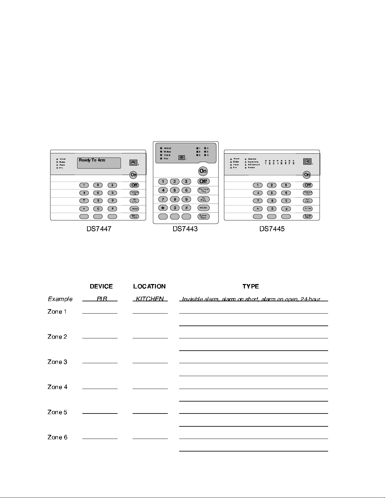
1.1 Understanding the DS7443, DS7445, and DS7447 Keypads
The DS7443 is a 6 zone LED keypad; its LEDs represent the zones of the system.
The DS7445 is an 8 zone LED keypad; its LEDs represent the zones of the system (LEDs for zones 7 and 8 are not used).
The DS7447 is an alpha-numeric LCD keypad.
All three keypads display information on various control panel functions. A built-in sounder is used to annunciate keystroke entries and as
an interior warning device.
Volume Control (DS7445 and DS7447 only): The keypad sounder volume can be adjusted using the [1] and [4] k eys along with the [*] key.
Hold the [*] key while pressing the [1] key to increase the volume or the [4] key to decrease the volume. The volume adjustment does not
affect the volume during an alarm.
Backlight Control (DS7447 only): The display backlight intensity can be adjusted using the [3] and [6] keys along with the [*] key . Hold the
[*] key while pressing the [3] key to increase the brightness or the [6] key to decrease the brightness.
NOTE: After the backlight and volume are adjusted, you must arm, then disarm the system once to store this information in the control
panel. These settings will be lost in the event of total power failure to the panel.
Page 4
DS7060 User Guide Copyright © 1996-97 Detection Systems, Inc. Page 29
Page 5
Page 28
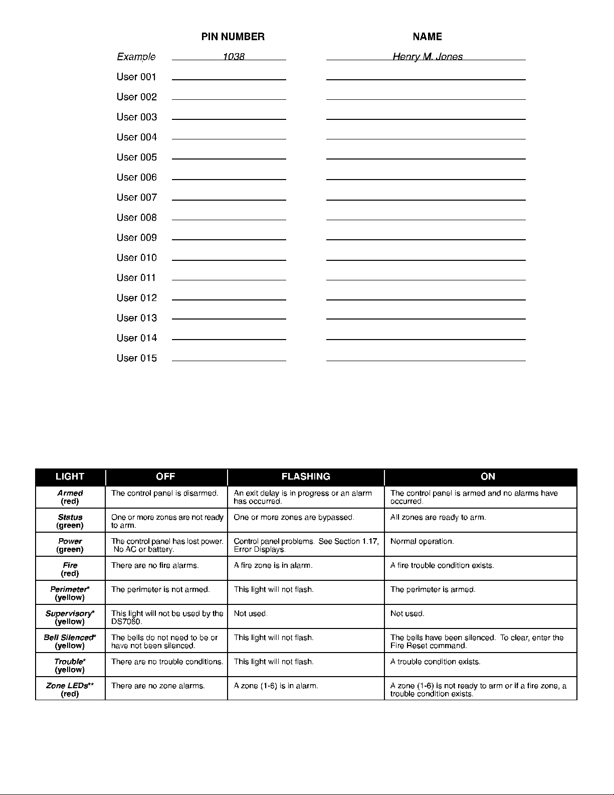
This chart will help you understand what each light/LED represents.
*= This light is present on the DS7445 only. **= This light is on the DS7443 and DS7445.
DS7060 User Guide Copyright © 1996-97 Detection Systems, Inc. Page 5
Page 6
1.2 Personal Identification Numbers
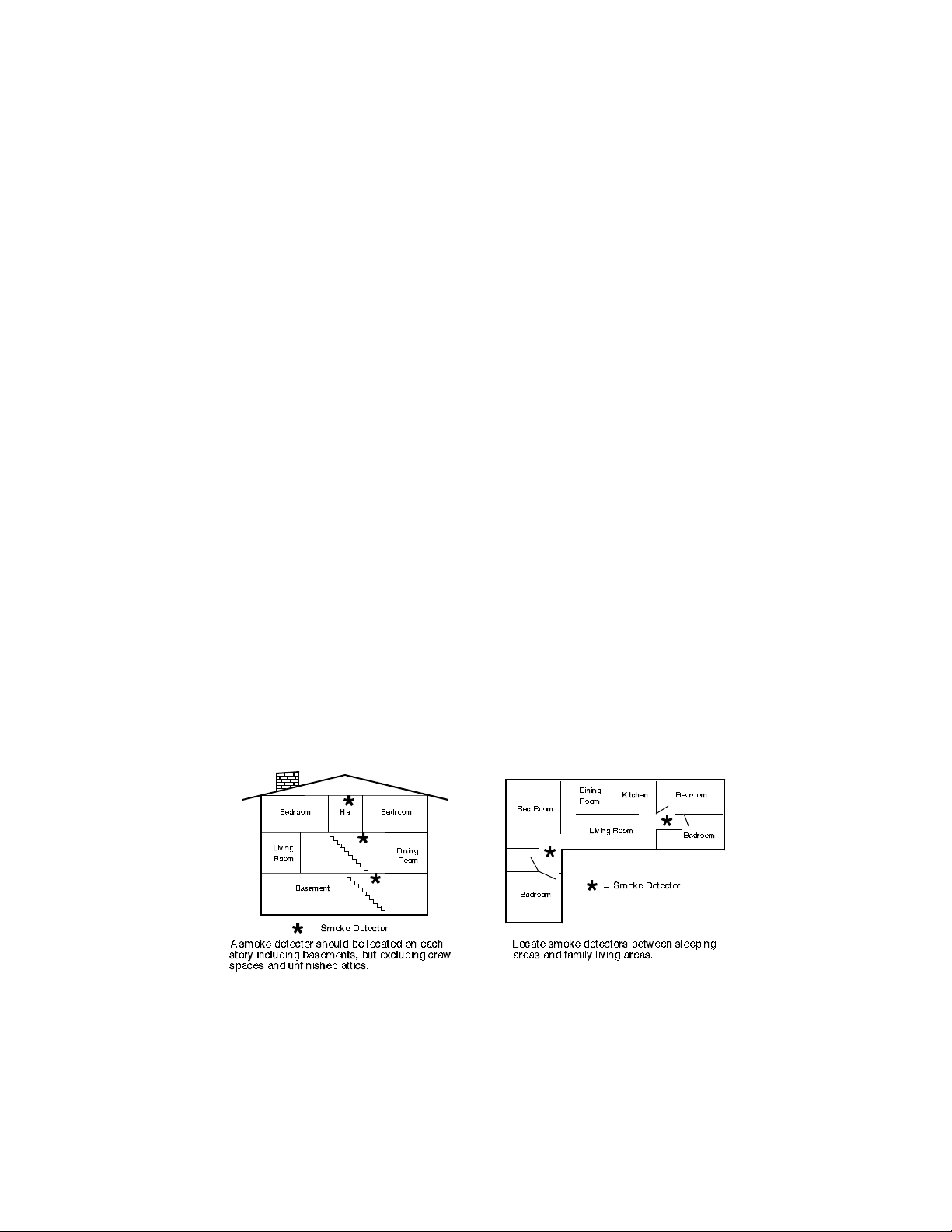
The Personal Identification Number (PIN) is the 4-digit code users enter at the keypad to gain access to the system. A PIN may be assigned
to each User Number 001-015. The User Number identifies each person using the system. There are 15 possib le User Numbers (001-015).
Your system may have up to 15 different PINs, each 4 digits long. Each User Number can have only one PIN. Attempting to assign the
same PIN to multiple User Numbers will result in the three-beep error tone, and the change will not be made.
User Number 001 is designated as a Master Code. It can be used to add, delete, read back, or change other PINs.
User Number 001 is shipped from the factory with the sequence of 1234. This code should be changed to one of your personal
preference. PINs should never be programmed with common sequences such as 1111 or 2468 because they are easily violated.
Page 6
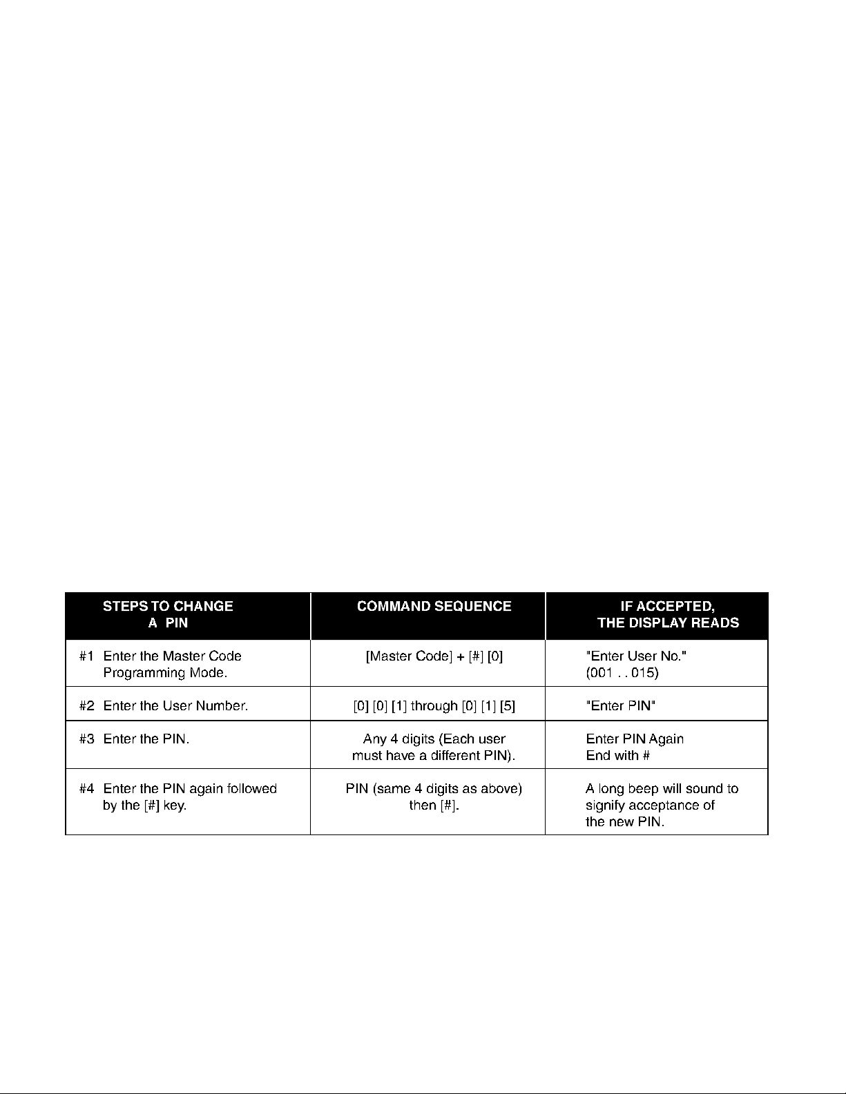
Adding a PIN
The following chart will guide you through the steps necessary to add or change a PIN. It is recommended that this procedure be performed
at a DS7447 keypad. No visual cues will be given from a DS7443 or DS7445 keypad.
• Do not install smoke detectors where normal area temperatures are above 100 degrees F (38 degrees C) or below 32 degrees F (0 degrees
C).
• Areas of high humidity and dust concentrations should be avoided.
The edge of ceiling mounted detectors should be no closer than 4 inches (10 cm) from any wall.
• Place the top edge of wall mounted detectors between 4 and 12 inches (10 to 30 cm) from the ceiling.
For exact mounting information, refer to the instructions provided with the smoke detectors.
DS7060 User Guide Copyright © 1996-97 Detection Systems, Inc. Page 27
Page 7
Page 26
Having and Practicing an Escape Plan
A fire warning may be wasted unless the family has planned in advance for a rapid and safe exit from the building.
• Draw a floor plan of the entire house showing two exits from each bedroom and two from the house. Since stairwells and hallways may be
blocked during a fire, the plan should provide exits from bedroom windows. Make copies of the plan and practice it with all family members.
• Prearrange a meeting place outside and away from the residence. Once out of the building, all occupants should immediately go to the pre-
selected location to be accounted for.
• Provide a barricade between family members and fire, smoke, and toxic gases (e.g. close all bedroom doors before retiring).
• Children should be instructed on opening their bedroom windows and exiting safely from the building. If exiting is not possible, they should be
taught to stay at the open window and shout for help until it arrives.
• In the event of a fire alarm after retiring, wake the children by shouting to them from behind your closed door. Tell them to keep their bedroom
doors closed.
• If the top of your bedroom door is uncomfortabl y hot, do not open it. There is most lik ely fire, intolerab le heat, or smoke on the other side.
Shout to all family members to keep their bedroom doors closed and to exit the building via alternate routes.
• If the top of the door is not uncomfortably hot, brace the bottom of the door with y our foot, and the top with one hand, then open the door about
one inch. Be prepared to slam the door shut if there is any pressure against the door or if any hot air rushes in.
• If there is no evidence of excessive heat or pressure, leave the room and close the door behind you. Shout appropriate instructions to all
family members and immediately leave the building via the pre-planned routes. If heavy smoke is present, drop to your hands and knees, or
crawl to remain below the smoke level.
Installation Considerations
Proper location of detection devices is one of the most critical factors in a fire alarm system.
The following are some general considerations:
• Smoke detectors should not be installed in “dead air” spaces or close to ventilating or air conditioning outlets because smoke may be
circulated away from the detector. Locations near air inlets should be favored.
• Avoid areas subject to normal smoke concentrations such as kitchens, garages, or near fireplaces.
NOTE: Users 014 and 015 may be used for Duress and Guest Codes. See Sections 1.18 and 1.19.
NOTE: You cannot read back User PIN numbers. You should keep a separate list for future reference.
Removing a PIN
To remove a PIN enter a [Master Code] [#] [0], the User Number of the PIN to be canceled, and then [#] again.
canceled.
DS7060 User Guide Copyright © 1996-97 Detection Systems, Inc. Page 7
See Sections 1.18 and 1.19 for special uses for User Number 14 and 15 PINs.
User Number 001 can not be
Page 8

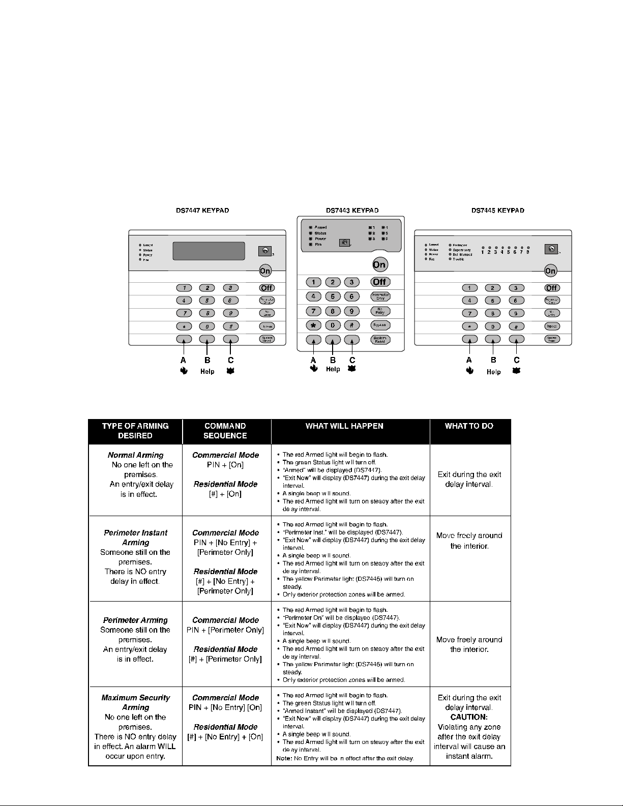
1.3 Turning ON (arming) the System
Page 8
The green
“Ready T o Arm” in order to arm the system with one of these commands.
If the green
Ready,” then see Section 1.7 Force Arming or Section 1.9 Zone Bypass for other w ays to arm the system.
NOTE: In commercial burglar applications for U. L. Listed Requirements, a ring-back indication and bell test should be heard after arming
NOTE: If the system has invisible zones that are not ready, they will be displayed during the arming sequence. The display of invisible z ones
The chart below explains the four normal ways of arming the system.
Status light must be on steady and no zone lights are displayed on the DS7443 or DS7445 keypad. The DS7447 display must read
Status light is not on, or zone lights are displayed on the DS7443 or DS7445 keypad, or if the DS7447's display is reading “Not
(closing). If not heard, call for service.
will remain on until the zone is cleared or bypassed.
The Emergency Alarm Keys [A], [B], and [C] may generate Fire, Special Emergency, and Panic Alarms if programmed by the installer . Ask your
installing company to explain the function of these keys.
When using the Emergency Alarm Keys, they must be pressed for two seconds to generate an alar m.
NOTE: If the Emergency Alarm keys are to be used, they should be labeled to signify their functions.
The “A” key should be labeled as the Fire key. This is the only key that may be designated as the Fire key.
The “B” key should be labeled as the Help key.
The “C” key should be labeled as the Panic key.
Use the Disarming Command Sequence to cancel or silence these alarms.
1.22 Fire Safety
This fire alarm system can provide early warning of a developing fire. Such a system, however, does not ensure protection against property
damage or loss of life resulting from a fire. An y fire alarm system may f ail to warn for an y number of reasons (e.g. smoke not reaching a detector
that is behind a closed door).
When considering detectors for residential applications, refer to NFPA Standard 72, “The National Fire Alarm Code.” This standard is available
at a nominal cost from: The National Fire Protection Association, Batter ymarch Park, Quincy, MA 02269.
If Installed in Family Residences
Adherence to the NFPA Standard 72 can lead to reasonable fire safety when the following items are practiced:
• Minimize hazards: Avoid the three traditional fire killers: smoking in bed, leaving children home alone, and cleaning with flammable liquids.
• Provide a fire warning system: Most fire deaths occur in the home, the majority, during sleeping hours. The minimum level of protection
requires smoke detectors to be installed outside of each separate sleeping area and on each additional story of the dwelling.
For added early warning protection, it is recommended that detectors be installed in all separated areas including the basement, bedrooms,
dining room, utility room, furnace room, and hallways.
DS7060 User Guide Copyright © 1996-97 Detection Systems, Inc. Page 25
Page 9
Caution When Entering A Building
If the bells and sirens are on and/or the red Armed light is flashing (with the DS7447 display reading “Zone Alarm” or the DS7443 or DS7445
having its zone LEDs flashing) then the keypad is signaling that an alarm has occurred. The k eypad will also issue a pulsed tone during the entry
delay instead of the usual steady tone.
If the alarm has not been previously investigated, do not enter the building unless accompanied by the appropriate Emergency Services’
personnel.
Fire Alarms
Fire Alarms are silenced by using the same procedure as intrusion alarms: a PIN + the [Off] key.
The Fire Alarm system is not reset until alarms at smoke detectors are cleared by using the [System Reset] command. The Fire Alarm system
will not be functional until this procedure has been followed. See the “Fire Reset” section.
1.21 Emergency Keypad Alarms
DS7060 User Guide Copyright © 1996-97 Detection Systems, Inc. Page 24
DS7060 User Guide Copyright © 1996-97 Detection Systems, Inc. Page 9
Page 10
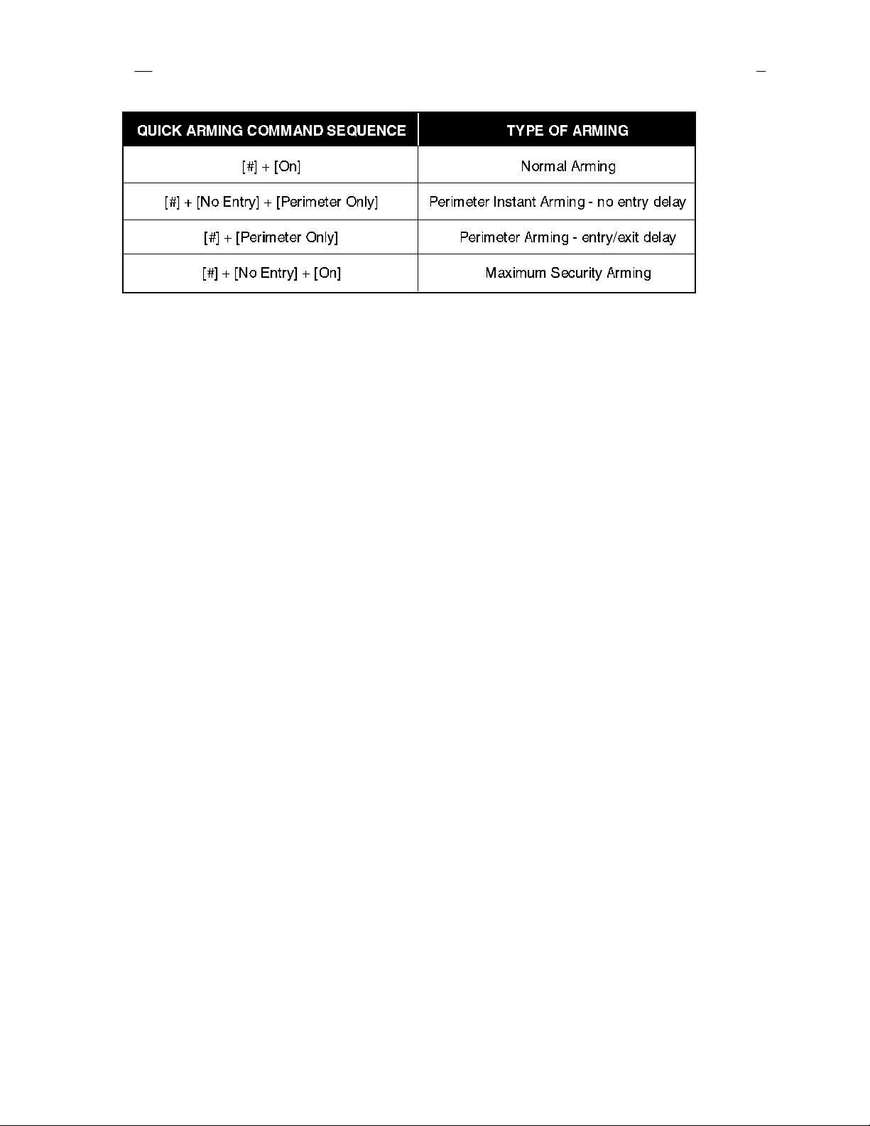
1.4 Quick Arming the System
Page 10
If Quick Arming is
following shortcuts are available. Ask your installation company if you desire this feature.
not used, a PIN must be entered at the beginning of all arming command sequences. When Quick Arming
is used, the
1.5 Easy Exit
If the system is armed and there have been no zones violated, then you can reenter a Quick Arm Command without first disarming the system.
This allows you to change the arming level or to restart the exit delay so you can exit through an entry/exit zone. Easy Exit is disabled by default.
Ask your installation company if you desire this feature.
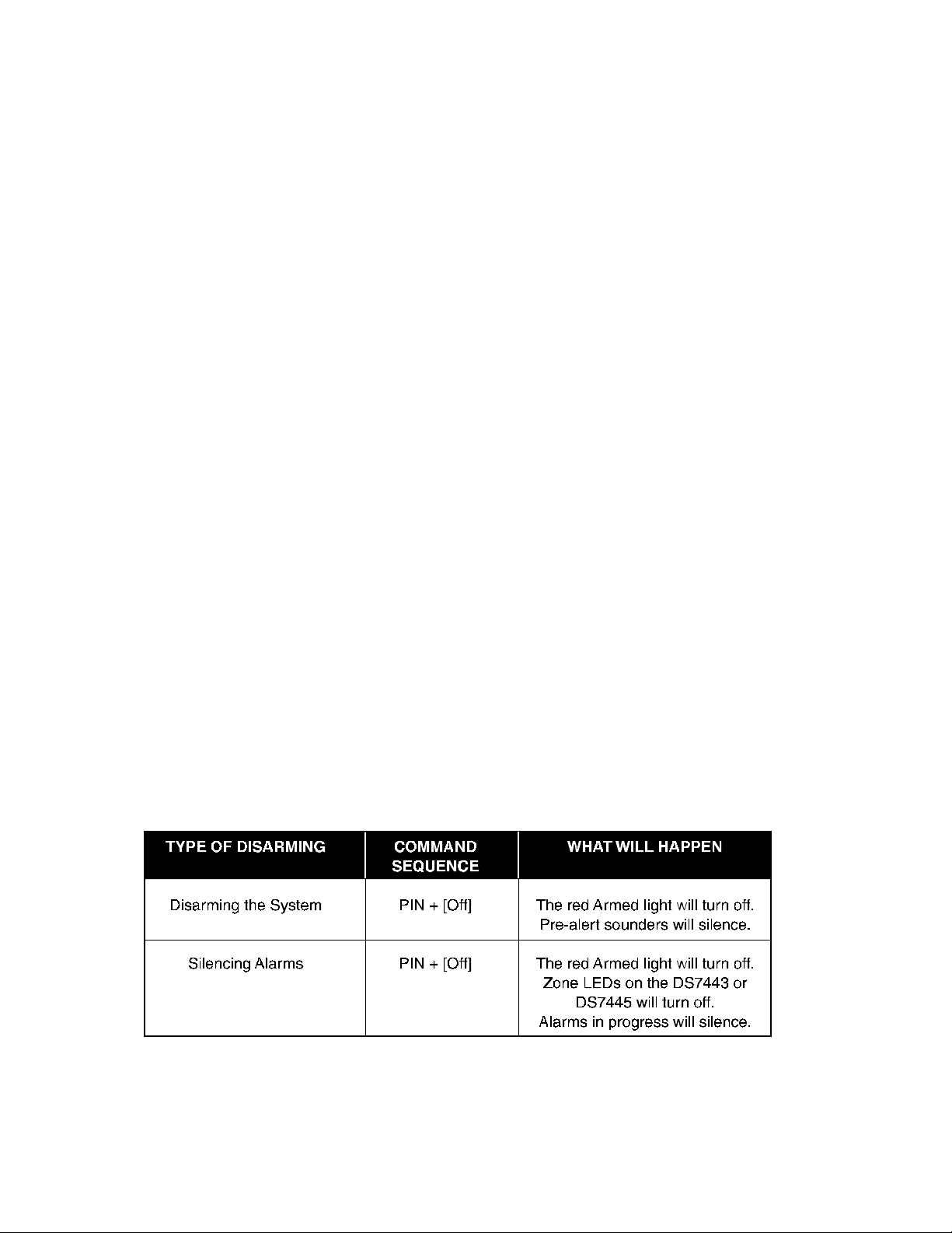
1.6 Turning OFF (disarming) the System/Silencing Alarms
Please read Section 1.20 Emergency Procedures prior to being confronted with an emergency event.
If you have entered the building through a perimeter door, you may hear a steady pre-alert tone from the keypads. If so, disarm according to the
chart below.
1.18 Duress Code
User Code 14 may be used as a duress PIN number. When the system is disarmed using this duress code, a silent report is sent to the central
station. Duress codes are intended to be used when a user is forced to disarm the system. Ask your installation company if you desire this
feature.
1.19 Guest Code
User Code 15 may be programmed to be a Guest Code. After the Guest Code has been programmed, it is enabled by depressing [PIN] + [#] [8]
[4]. The Guest Code may now be used to arm and disarm the system. It remains activ e until the panel is disarmed with any other valid code. Ask
your installation company if you desire this feature.
1.20 Emergency Procedures
Identifying Alarm Sounds
Your alarm system may be programmed for a steady alarm sound or a pulsed alarm sound. It is important to learn the difference between a fire
alarm sound and an intrusion alarm sound before you are confronted with an actual emergency.
Silencing Alarms
All alarms can be silenced with any PIN. Entering your PIN + [Off] will silence the alarm and turn off (disarm) the control.
A Cautionary Note
How you respond to an alarm will depend, mostly, on the type and time of the alarm. You should seek the advice of your installing company as
they install your system, not later (e.g. after an alarm) to develop a response plan.
Above All Else, Common Sense Should Prevail
If there is any threat or hint of danger to yourself or others on the premises, such as in the event of a fire alarm, everyone should be instructedto
leave the premises immediately. Do not enter the premises unless accompanied by the appropriate Emergency Services’ personnel, or after
they have given the OK to enter.
DS7060 User Guide Copyright © 1996-97 Detection Systems, Inc. Page 23
Page 11
Page 22
** = Battery Trouble and Communicator Err displays must be cleared by the [System Reset] command sequence even after the problem has
been remedied. These displays will not self clear. All the other error displays will self clear from the keypads once the problem has been
remedied.
1. DS7447 - “AC Power Failure”
DS7443 or DS7445 - LED 1 turns on steady
There is a power failure and the panel is operating on backup battery.
2. DS7447 - “Battery Trouble”
DS7443 or DS7445 - LED 2 turns on steady
If the system has just been through a power failure, wait at least two hours for the battery to recharge, then enter a PIN + [System Reset] to
perform a battery test.
3. DS7447 - “Communicator Err”
DS7443 or DS7445 - LED 3 turns on steady
The communicator failed to communicate with the central station.
4. DS7447 - “System Fault”
DS7443 or DS7445 - LED 4 turns on steady
Internal error in the control circuitry or optional circuitry. These system faults are: Ram Fault, ROM Fault, EEPROM Fault.
5. DS7447 - “Keypad Fault”
DS7443 or DS7445 - LED 5 turns on steady
One of the keypads is not responding to the control panel.
6. DS7447 - “Aux Power Fault”
DS7443 or DS7445 - LED 6 turns on steady
The auxiliary power has been shorted.
7. DS7447 - “Zone Trouble”
DS7443 or DS7445 - LED of the zone in trouble will light
One of the zones is not responding to the control panel. This may also be displayed during power-up (if so, ignore).
WARNING: If the bells and sirens are on and/or the red Armed light is flashing, then the keypad is signaling that an alarm has occurred
sometime before your arrival. The DS7447 will display “Zone Alar m.” The DS7443 or DS7445 zone LEDs will be flashing for the
corresponding zone that is in alarm.
• The keypad will also issue a pulsed tone during the entry delay instead of the usual steady tone.
• If the alar m has not been previously investigated, do not enter the building unless accompanied by the appropriate Emergency Services’
personnel.
This chart explains proper procedures for disarming and/or silencing alarms.
Turning Off (disarming) the System under Duress
A duress code is used when someone demands, by threatening your life or well-being, that the system be turned off. When used, the code will
both turn off the system and report a silent duress alarm if connected to a monitor ing service. User code 14 can be optionally configured as a
duress code. User code 14 will not arm the system, or report duress, if the system is not armed. Extreme care should be used when entering
your PIN to turn off the system, so a duress code is not inadvertently entered. User Code 14 is not a duress code by default. You must program
the control panel that User Code 14 is the duress code. Ask your installation company if you desire this feature.
DS7060 User Guide Copyright © 1996-97 Detection Systems, Inc. Page 11
Page 12
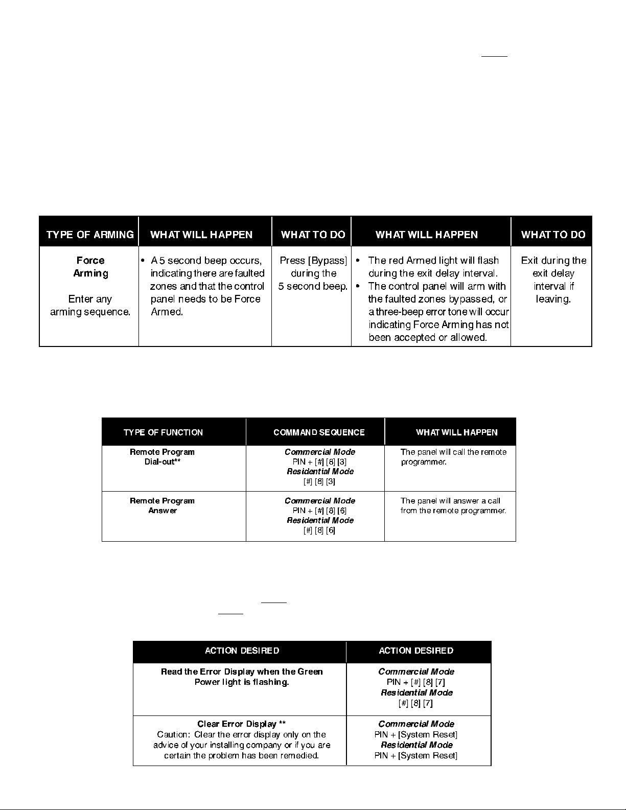
1.7 Force Arming
Page 12
When one or more zones are faulted, the system may be Force Armed by bypassing the faulted zones. The green
keypads when Force Arming is required to arm the system. The DS7447 display will read “Not Ready” or “Fire Trouble” (if a fire zone is open)
and the DS7443 and DS7445 zone LEDs (1-6) will be on if one of those zones is faulted. Ask your installation compan y if you desire this feature .
Force Arming during an AC power f ailure: Regular arming of the control panel is not permitted during an AC power failure. Ha ving to Force Arm
serves as a warning that the control panel is operating under backup battery.
WARNING: Bypassing or Force Arming removes some of your building's protection because it excludes the faulted zones from arming.
Therefore, an intrusion may not be detected or the detection ma y be delayed. Always attempt to correct an y zone problems (close
doors and windows, etc.) before using these features. If the problem can not be corrected, contact your installing company.
NOTE: See Section 1.9 Zone Bypass for an alternate method of arming the system when faults exist. Force arming is not available in
U. L. Listed systems.
Status light will be off on all
** = Phone numbers 1 and 3 must be programmed. Phone #1 Account Code must be programmed.
1.17 Error Displays
Control panel problems are indicated by a flashing green
DS7443 and DS7445 will only flash the green
installing company if the problems persist.
DS7060 User Guide Copyright © 1996-97 Detection Systems, Inc. Page 21
Power light. The error messages may only be read when the control is disarmed. Contact your
Power light. The DS7447 display will also read “Control Trouble, Enter [#] [8] [7].” The
Page 13
Fire T rouble
Page 20
A Fire Trouble display signifies a problem with the fire system, such as a break in the wiring that monitors smoke detectors.
A Fire Trouble will be indicated by a short beep from the keypad sounders every 10 seconds. The DS7447 will display “Fire T rouble” followed
by the zones in a trouble condition. The DS7443 will turn the
tur n the
Notify your installing company immediately if the Fire Trouble message is displayed.
The Fire Trouble beep can be silenced with any PIN followed by the [Off] key. After problems have been remedied, a PIN followed by [System
Reset] should be entered to clear the “Fire T rouble” display.
Fire and Trouble lights on steady and will light the corresponding zone LEDs.
Fire light on steady and will light the corresponding zone LEDs. The DS7445 will
1.16 Remote Program Dial-out and Answer
Note: These features should be used by qualified installation personnel only.
Call for Remote Programming
This command can only be entered when the control is disarmed. Phone numbers 1 and 3 must be programmed, along with account code 1.
The panel will call phone number 3 and attempt to connect for downloading. While programming is underway the Status, Armed, and Power
LEDs will flash. If the panel is already using the phone line, it will sound the three beep error tone.
Answer for Remote Programming
The panel will automatically pick up the phone line to answer a remote programming call. While programming is underway the Status, Armed,
and Power LEDs will flash. If the panel is already using the phone line for a report communication, it will sound the three beep error tone. This
command can only be entered when the control is disarmed.
This chart will help you to call or answer the Remote Programmer.
1.8 Auto Bypass
The system can be armed and will automatically bypass faulted zones. Ask your installation company if you desire this feature.
1.9 Zone Bypass
There may be occasions when it is desirable or necessary to temporarily bypass one or more zones prior to arming the system. Bypass
commands only work when the control panel is disarmed. For instance, an open window may cause the DS7447 display to read "Not Ready"
followed by the zone number. The DS7443 or DS7445 may have one of its zone LEDs on steady.
Only one zone may be bypassed each time the command is used. If more than one zone requires bypassing, repeate the command for each
zone to be bypassed.
NOTE: See Section 1.7 Force Arming for another method of zone bypassing.
DS7060 User Guide Copyright © 1996-97 Detection Systems, Inc. Page 13
Page 14
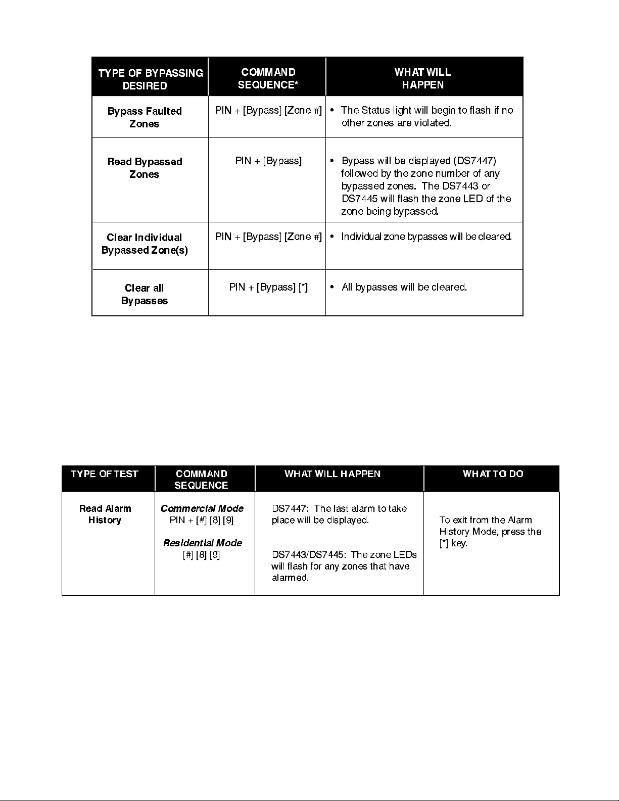
This chart explains the procedure for bypassing a faulted zone prior to arming the system.
Page 14
* If in “Residential Mode” substitute the [#] key for the PIN.
NOTE: All bypasses are cleared when the system is disarmed, unless they are on 24-hour zones. To clear a bypass on a 24-hour zone, use
Clear Individual or Clear All.
1.14 Read Alarm History
This feature will display which zones were in alarm during the last armed period. The alarm memory will remain from one armed cycle to the next
if no new alarms occur. Alarm memory will clear when enter ing programmers mode.
To exit the Alarm Histor y Mode, press the [*] key or wait 5 seconds and the keypad will exit automatically.
1.15 Fire Reset/Fire Trouble
Fire Reset
During a fire alarm, exit the premises immediately. When you have determined there is no fire, you may silence the bells/sirens before you can
initiate the [System Reset] command. PIN + [Off] will silence the sounders.
This will allow a determination of which smoke detector has alarmed so the monitoring company may verify its operation.
A PIN followed by the [System Reset] key will reset any smoke detectors after a fire alarm has occurred.
The System Reset command will perform a fire reset, will perform a battery test, and will clear all system troubles.
DS7060 User Guide Copyright © 1996-97 Detection Systems, Inc. Page 19
Page 15
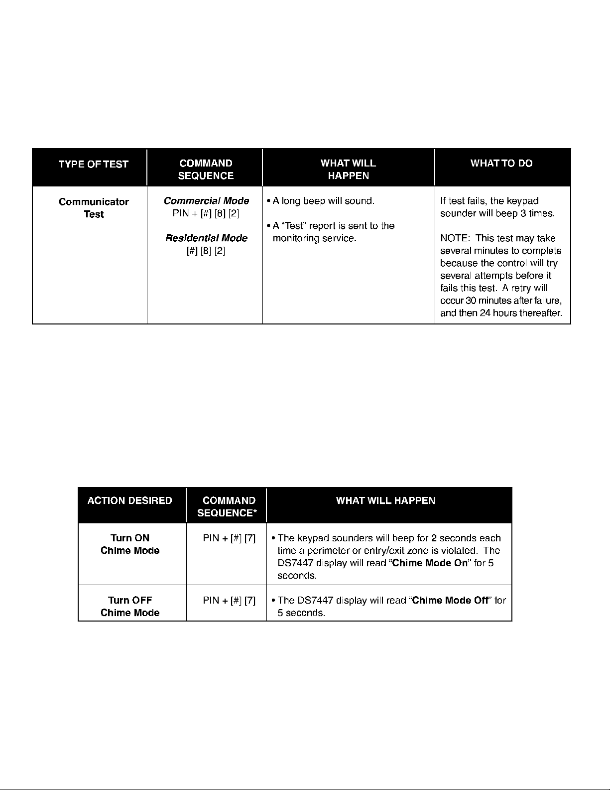
1.13 Communicator Test
This test is only available if your system transmits alar ms and system information to a monitoring service, and has been programmed by the
security installing company to permit communicator tests. This test may only be used in the disarm mode.
A long beep will initially sound to acknowledge the start of the test. If the test is successful, the sounder will again issue one long beep. If the test
fails, the keypad sounder will beep three times and the Power LED will begin to flash, indicating a Control Trouble. The DS7447
keypad will display “Control Trouble Enter #87. When performing the #87 error displa y sequence, the DS7447 keypad will display “Control Trouble
Communication Err”. The DS7443 and DS7445 keypads will turn on the Zone 3 LED. See Section 1.17.
Page 18
1.10 Chime Mode
Chime Mode causes the keypad sounders to beep each time a Perimeter or Entry/Exit zone is violated while the control panel is off (disarmed).
The [#] [7] command is used to both turn Chime Mode off and on.
This chart explains the procedure for turning ON and turning OFF Chime Mode.
* If in “Residential Mode” substitute the [#] key for the PIN.
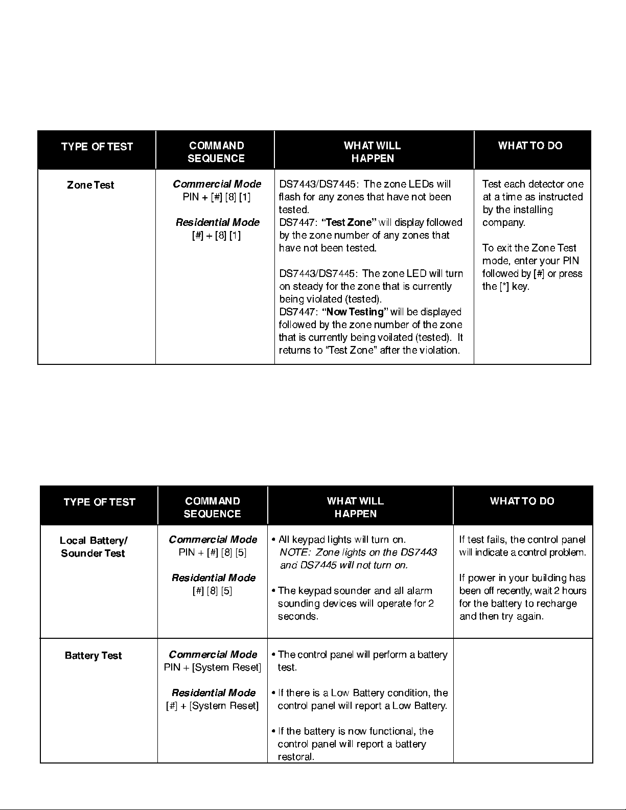
1.11 Zone Test
The Zone Test is used to confirm that detectors will report alarms. Zone T est works on all zones, except 24-hour z ones and fire z ones. While the
keypad is in Zone Test, no control panel alarms will activate an alarm, except 24-hour z one alarms and fire alarms. These will override the Zone
Test function.
Caution: Be sure not to activate 24 hour or fire zones during the zone test or an alarm signal will be sent.
The Zone Test will initiate communicator reports only if both “System in Test Report” and “System in Test Restoral Report” are prog rammed. Ask
your installation company if you desire this feature.
DS7060 User Guide Copyright © 1996-97 Detection Systems, Inc. Page 15
Page 16
Page 16
WARNING: Make sure that the report value prog rammed at these locations will be clearly understood at the Central Station. The “System
in Test Report” will be sent, followed by the alarm and restoral reports of the zones being tested, pro viding their corresponding
report address is programmed. After completion of the Zone Test, the “System in Test Restoral Report” will be sent. If these
two reports are misunderstood, then the zone alarms might be perceived as a real violation.
1.12 Local Battery/Sounder Test
This test uses the battery to manually activate all the system sounders for two seconds. If the battery voltage is low, a battery fault will occur.
DS7060 User Guide Copyright © 1996-97 Detection Systems, Inc. Page 17
 Loading...