

Page 1
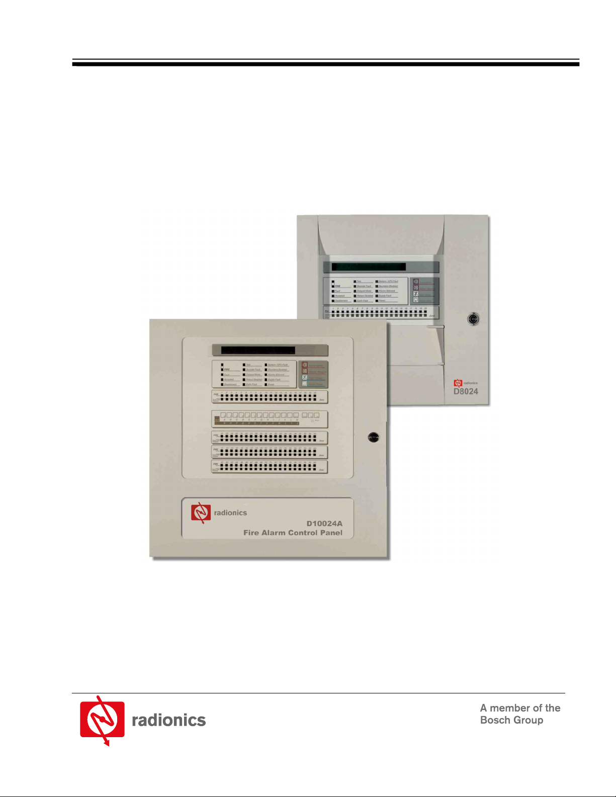
D8024/D10024A Fire Alarm Control Panels
User Manual
Page 2

D8024/D10024A User Manual
50618B Page 2 © 2002 Radionics
Page 3

D8024/D10024A
Contents
1.0 Introduction......................................................................................................... 5
1.1 Other Literature Referenced ............................................................................................................................. 5
1.2 Documentation Conventions............................................................................................................................. 5
1.2.1 Type Styles Used in this Manual ...................................................................................................................... 5
1.2.2 Tips, Important Notes, Cautions and Warnings................................................................................................ 5
1.3 UL/National Approvals ...................................................................................................................................... 6
1.4 EMC Compatibility ............................................................................................................................................ 6
2.0 User Control Levels ............................................................................................ 7
2.1 Level Definition ................................................................................................................................................. 7
2.2 User Passwords................................................................................................................................................ 7
3.0 Controls and Displays ........................................................................................ 9
3.1 Controls............................................................................................................................................................. 9
3.1.1 Control Keys ..................................................................................................................................................... 9
3.1.2 Alphanumeric/Interactive Control Keys........................................................................................................... 10
3.1.3 System Control LED Indications ..................................................................................................................... 10
3.1.4 Zone LED Displays ......................................................................................................................................... 11
3.1.5 LCD Display Indications.................................................................................................................................. 12
4.0 Level 1 Display Functions................................................................................ 13
4.1 Normal Conditions .......................................................................................................................................... 13
4.2 Power Fail Conditions.....................................................................................................................................13
4.3 Fire Alarm Conditions ..................................................................................................................................... 13
4.4 Trouble Conditions.......................................................................................................................................... 13
5.0 Level 2 Control Functions................................................................................ 15
5.1 Power Failure Condition ................................................................................................................................. 15
5.1.1 Power Failure Indication ................................................................................................................................. 15
5.1.2 User Actions.................................................................................................................................................... 15
5.2 Trouble Conditions.......................................................................................................................................... 15
5.2.1 Trouble Indication ........................................................................................................................................... 15
5.2.2 User Actions.................................................................................................................................................... 15
5.3 Fire Alarm Conditions ..................................................................................................................................... 16
5.3.1 Fire Alarm Indications ..................................................................................................................................... 16
5.3.2 User Actions.................................................................................................................................................... 16
5.4 User Option Functions .................................................................................................................................... 16
5.4.1 Test ................................................................................................................................................................. 16
5.4.1.1 LEDs Test ....................................................................................................................................................... 17
5.4.1.2 LCD Test......................................................................................................................................................... 17
5.4.1.3 Zones Test...................................................................................................................................................... 17
5.4.1.4 Output Test ..................................................................................................................................................... 18
5.4.1.5 Time ................................................................................................................................................................ 18
5.4.1.6 Enable / Disable Functions ............................................................................................................................. 18
5.4.1.7 Enable or Disable Zones ................................................................................................................................ 18
5.4.1.8 Enable or Disable Inputs................................................................................................................................. 19
5.4.1.9 Networked Panels........................................................................................................................................... 19
5.4.1.10 Enable or Disable Keys .................................................................................................................................. 19
5.4.1.11 Enable or Disable Delayed Day Modes.......................................................................................................... 20
5.4.1.12 Enable or Disable Outputs.............................................................................................................................. 20
5.4.1.13 Print................................................................................................................................................................. 21
5.4.2 View ................................................................................................................................................................ 21
6.0 Delayed Day Mode Operation .......................................................................... 23
6.1 Stage 1............................................................................................................................................................ 23
6.2 Stage 2............................................................................................................................................................ 23
D8024/D10024A User Manual
© 2002 Radionics Page 3 50618B
Page 4

D8024/D10024A
Contents
7.0 Level 3 Programmer Functions........................................................................ 25
8.0 Log Book............................................................................................................ 27
8.1 REFERENCE DATA .......................................................................................................................................27
8.2 EVENT DATA.................................................................................................................................................. 28
Figures
Figure 1: D8024/D10024A Controls and Displays.................................................................................................................. 9
Figure 2: Control Keys............................................................................................................................................................ 9
Figure 3: Alphanumeric and Interactive Control Keys .......................................................................................................... 10
Figure 4: System Control LED Display ................................................................................................................................. 10
Figure 5: Zone LED Display .................................................................................................................................................11
Figure 6: LCD Display – 80 characters on 2 lines ................................................................................................................ 12
Figure 7: Normal Display – Date and Time ..........................................................................................................................12
Figure 8: Enable Control Keys?............................................................................................................................................ 12
Tables
Table 1: Other Literature Referenced..................................................................................................................................... 5
Table 2: Control Key Functions ..............................................................................................................................................9
Table 3: Alphanumeric and Interactive Control Keys ...........................................................................................................10
Table 4: LED Functions ........................................................................................................................................................ 11
Table 5: Zone LED Functions............................................................................................................................................... 12
Table 6: User Menu Options................................................................................................................................................. 16
Table 7: Print Options........................................................................................................................................................... 21
Table 8: View Mode Options ................................................................................................................................................21
Table 9: Logbook Reference Data........................................................................................................................................ 27
Table 10: Logbook Event Data ............................................................................................................................................. 28
D8024/D10024A User Manual
50618B Page 4 © 2002 Radionics
Page 5
1.0 Introduction
• The material and instructions covered in this manual have been carefully checked for accuracy and are
presumed to be correct. However, the manufacturer assumes no responsibility for inaccuracies and
reserves the right to modify and revise this document without notice.
• These instructions cover the use and operation of the Fire Alarm Control Panel. Refer to the
D8024/D10024A Operation and Installation Manual
for information on programming and Level 3 functions.
1.1 Other Literature Referenced
Throughout this manual, references will be made to other documentation. See the following table (which lists the
complete part number for ordering purposes) for a list of other literature offering more information on the
D8024/D10024A Fire Alarm Control Panels.
Name of document Part Number
D8024/D10024A Operation and Installation Manual
Table 1: Other Literature Referenced
1.2 Documentation Conventions
These conventions are intended to call out important features, items, notes, cautions, and warnings that the
reader should be aware of in reading this document.
1.2.1 Type Styles Used in this Manual
To help identify important items in the text, the following type styles are used:
Bold text usually indicates selections that you may use while programming your panel. It may
also indicate an important fact that should be noted.
Bold Italicized
Italicized text
Courier Text
[CAPITALIZED TEXT] Text like this is used to indicate to the user that a specific key should be pressed.
1.2.2 Tips, Important Notes, Cautions and Warnings
Throughout this document, helpful tips, important notes, cautions and warnings will be presented for the reader
to keep in mind. These appear different from the rest of the text as follows;
Important Notes - should be heeded for successful operation and programming. Also tips and
shortcuts may be included here.
used to denote notes, cautions and/or warnings
Is used to reference the user to another part of this manual or another manual
entirely. It is also used to symbolize names for records that the user will create.
Text that appears like this indicates what may appear on the Control Panel display,
command center/keypad or internal printer.
Example: …press the [ESC] key…
D8024/D10024A
Introduction
(P/N 50616) for details of how to install the system and
50616
Caution - These caution the operator that physical damage to the program and/or equipment may
occur.
Warning - These warn of the possibility of physical damage to the operator, program and/or
equipment.
D8024/D10024A User Manual
© 2002 Radionics Page 5 50618B
Page 6

D8024/D10024A
Introduction
1.3 UL/National Approvals
• UL Listed for “Local” or “Remote Station” use.
This equipment must be installed in accordance with these instructions, NFPA72 and the appropriate
national, regional and local regulations specific to the country and location of the installation. Consult with
the appropriate Authority Having Jurisdiction (AHJ) for confirmation of the requirements.
1.4 EMC Compatibility
• This equipment has been tested and found to comply with the limits for a Class A digital device, pursuant to
Part 15 of the FCC Rules. These limits are designed to provide reasonable protection against harmful
interference when the equipment is operated in a commercial environment. This equipment generates, uses
and can radiate radio frequency energy, and, if not installed and used in accordance with the instruction
manual, may cause harmful interference to radio communications. However, there is no guarantee that
interference will not occur in a particular installation. Operation of this equipment in a residential area is
likely to cause harmful interference in which case, the user will be required to correct the interference at his
own expense.
• If this equipment does cause harmful interference to radio or television reception, which can be determined
by turning the equipment on and off, the user is encouraged to try to correct the interference by one or more
of the following measures:
- Reorient or relocate the receiving antenna.
- Increase the separation between the equipment and the receiver.
- Connect the equipment into an outlet on a circuit different from that to which the receiver is connected.
- Consult the dealer or an experienced radio/TV technician for help.
D8024/D10024A User Manual
50618B Page 6 © 2002 Radionics
Page 7

2.0 User Control Levels
2.1 Level Definition
• The D8024 and D10024A Fire Alarm Control Panels have three user control levels.
• At all three levels, the LED Displays indicate the condition of the installation, the Zone LED Displays indicate
the location of any fire alarm or trouble and the alphanumeric display gives more detailed fire alarm or
trouble information.
• At USER LEVEL 1, all the displays are functional but the front panel control keys are inhibited.
• At USER LEVEL 2, all front panel controls are functional and some system operation parameters and
functions can be changed. User Level 2 is reached by entering a password from level 1.
• At USER LEVEL 3, all front panel controls are functional and full system configuration and programming are
possible. User Level 3 is reached by entering a password from either Level 1 or Level 2. User Level 3 is
intended for use by the system installer / maintenance contractor.
2.2 User Passwords
• Up to ten USER LEVEL 2 passwords can be programmed into the panel.
• The USER LEVEL 2 passwords can be assigned / changed at Level 3 by the installer / maintenance
contractor. Level 2 passwords do not allow access to Level 3 functions.
D8024/D10024A
User Control Levels
D8024/D10024A User Manual
© 2002 Radionics Page 7 50618B
Page 8

D8024/D10024A
User Control Levels
Notes:
D8024/D10024A User Manual
50618B Page 8 © 2002 Radionics
Page 9
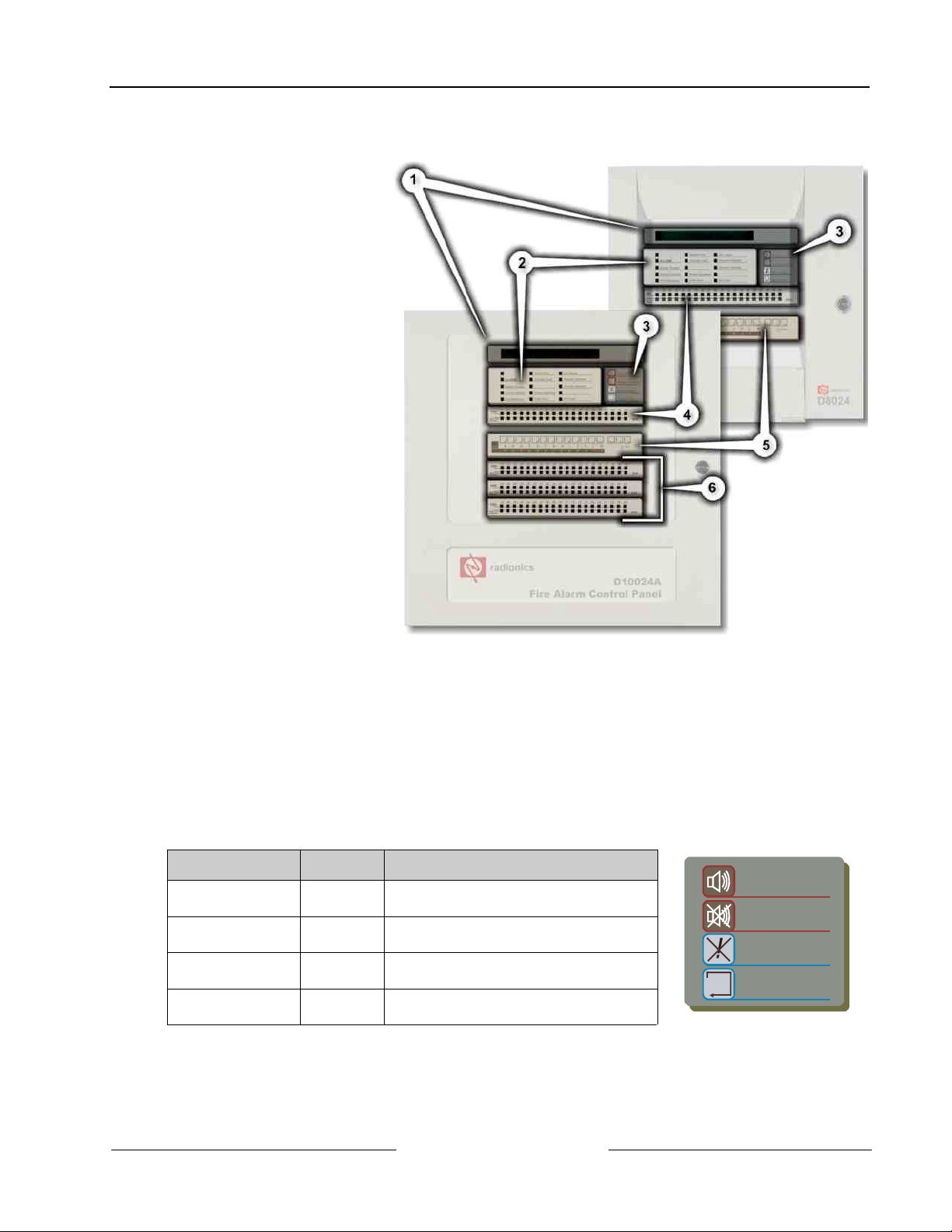
3.0 Controls and Displays
1. LCD Display
(See Section 3.1.5
Alphanumeric/Interactive
Control Keys on page 12)
2. System Control LED
Indicators (
3.1.3 System Control LED
Indications on page 10
3. Control Keys – A bank of
four keys contains the four
system control keys: Sound
Alarms, Silence/Resound,
Mute/Accept and System
Reset. (
Control Keys on page 9
4. Zone LED Display (
Section 3.1.4 Zone LED
Displays on page 11
5.
Alphanumeric/Interactive
Control Keys - A bank of 17
keys contains interactive
and alphanumeric keys.
See Section
(
6. 3.1.2
Alphanumeric/Interactive
Control Keys on page 10
See Section
)
See Section 3.1.1
)
See
)
)
D8024/D10024A
Controls and Displays
On the D8024, opening the
hinged panel gives access
these keys. This is located
below the Zone LED
Display.
The alphanumeric keys normally function as a numeric keypad. During programming, these keys can be
toggled to Letter Keys by pressing the [Change] key. This gives access to letters A-M. For access to letters
N-Z, press and hold the [Shift] key while pressing the appropriate letter key.
7. Optional Zone LED Display (
3.1 Controls
The control panel has two groups of control keys.
3.1.1 Control Keys
Key Legend Purpose Function
Sound Alarms Fire Drill Press to Turn on ALL NAC Outputs (i.e.
Silence / Resound Alarm
Mute / Accept Trouble
System Reset System
Figure 1: D8024/D10024A Controls and Displays
See Section 3.1.4 Zone LED Displays on page 11
evacuate building manually).
Press to Turn off all activated NACs.
Silence
Silence
Reset
Table 2: Control Key Functions
Press again to re-activate the NACs.
Press to acknowledge events and
silence the internal buzzer.
Press to cancel all alarm conditions and
reset the panel.
)
Sound Alarms
Silence / Resound
Mute / Accept
System Reset
Figure 2: Control Keys
D8024/D10024A User Manual
© 2002 Radionics Page 9 50618B
Page 10
D8024/D10024A
Controls and Displays
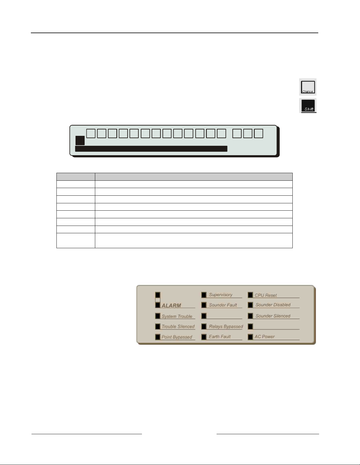
3.1.2 Alphanumeric/Interactive Control Keys
A bank of 17 keys contains interactive and alphanumeric keys. On the D8024, these keys can be accessed by
opening the hinged panel located below the Zone LED Display.
The alphanumeric keys normally function as a numeric keypad.
During programming, these keys can be toggled to Letter Keys by pressing the [Change] key. This
gives access to letters A-M.
For access to letters N-Z, press and hold the [Shift] key while pressing the appropriate letter key.
0 123456789 ><
ABCDEF GHIJKL
Shift
NOP Q RS TUVW XY
Figure 3: Alphanumeric and Interactive Control Keys
Key Legend Function
0 to 9 Press to enter numbers 0-9 or letters A-Z
> Press to scroll through fire alarms or troubles manually on the display
< Press to scroll back through fire alarms or troubles manually on the display
Change Press to change a display option (where allowed)
Enter Press to confirm entry of a multiple digit number
No Press to answer No, or terminate a display option
Yes Press to answer Yes, or step through a display option
Shift Press to show user options on the display
Press, during programming, to allow entry of Letters N-Z
Table 3: Alphanumeric and Interactive Control Keys
The control keys are disabled at USER LEVEL 1. Pressing the [Shift] key will cause the display to prompt for
entry of the Level 2 password.
3.1.3 System Control LED Indications
• The Level 1 LED
Indicators are divided into
two sections.
• The upper array of LED
Indicators shows the
operational conditional of
the panel and the
installation.
• The lower array of Zone
LED Indicators shows the
location of a fire alarm or
trouble.
Enter
Change
M
Z
No Yes
0,9 Wor ds
A Z
Figure 4: System Control LED Display
• The standard Zone LED Indicators provide identification for up to 20 zones. On the D10024A panel, this can
be extended by adding either a further 20 zones (to give a total of 40 zones) or a further 60 zones (to give a
total of 80 zones).
D8024/D10024A User Manual
50618B Page 10 © 2002 Radionics
Page 11
• The LED Indicators illuminate as red, yellow or green to give a clear indication of the panel status as follows:
Indicator Color Function How to Clear
Blank
ALARM Red The panel has detected a fire
alarm condition, or the ‘Fire
Drill’ key has been pressed.
System Trouble
Trouble Silenced
Point Bypassed
Supervisory
Sounder Fault
Yellow A trouble has been detected by the
panel.
Yellow A trouble has been acknowledged
and the internal buzzer silenced.
Yellow Part of the system, either input or
output, has been disabled manually
by the user.
Yellow This indicates a closed sprinkler
supervisory valve, pressure switch
or sprinkler system trouble
condition.
Yellow This indicates a wiring fault with one
of the NAC output circuits.
Blank
Relays Bypassed
Earth Fault
CPU Reset
Sounders Disabled
Sounders Silenced
Yellow The relay outputs have been
disabled.
Yellow An earth connection fault has
occurred on a cable.
Yellow The CPU has reset or a system
fault has occurred.
Yellow The NAC outputs have been
disabled.
Yellow The NAC outputs have been
silenced.
Blank
AC Power
Green STEADY: Indicates AC Power is
present. FLASHING: Indicates a
loss of AC Power or power supply
fault.
Table 4: LED Functions
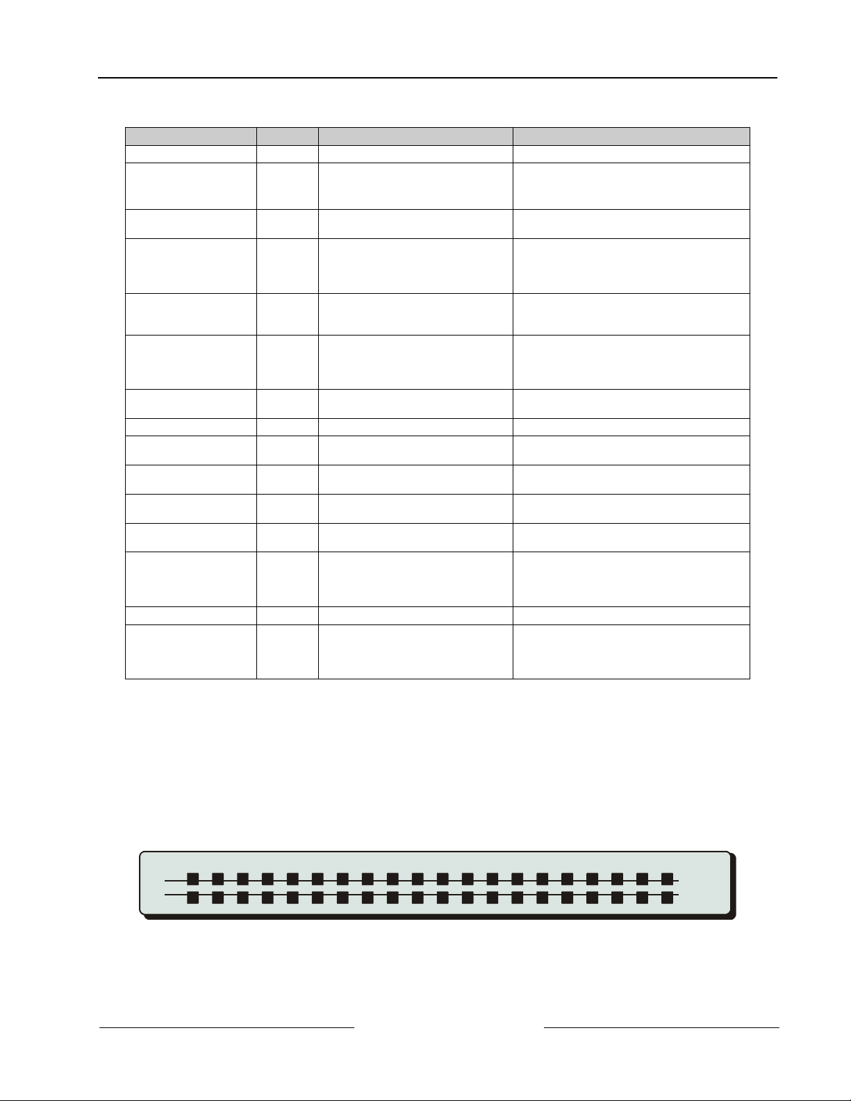
3.1.4 Zone LED Displays
The Level 1 LED Indicators are divided into two sections.
The upper array of LED Indicators shows the operational conditional of the panel and the installation. The lower
array of Zone LED indicators shows the location of a fire alarm or trouble.
The standard Zone LED Indicators provide identification for up to 20 zones. On the D10024A panel, this can be
extended by adding either a further 20 zones (to give a total of 40 zones) or a further 60 zones (to give a total of
80 zones).
The LED Indicators illuminate as red, yellow or green to give a clear indication of the panel status as follows:
D8024/D10024A
Controls and Displays
Correct the condition causing the alarm
and then perform a panel reset.
Correct the condition causing the trouble and
then perform a panel reset.
Correct the condition causing alarm or
trouble and then perform a manual reset.
NOTE: If another alarm or trouble occurs, the
internal buzzer automatically resounds.
Re-enable the device or devices. The system
automatically resets.
Correct the supervisory condition and then
perform a panel reset.
Correct the trouble condition and then
perform a panel reset.
See Point Bypassed.
Correct the trouble condition and then
perform a panel reset.
Correct the problem, if appropriate, and then
perform a panel reset.
See Point Bypassed.
Correct the alarm condition and then perform
a panel reset. NOTE: Press ALARM
SILENCE again to reactivate the NACs. If a
new alarm occurs, the alarms will resound.
N/A
ALARM
Trouble
1 202345678910111213141516171819
Zone
Figure 5: Zone LED Display
D8024/D10024A User Manual
© 2002 Radionics Page 11 50618B
Page 12
D8024/D10024A
Controls and Displays
Indicator Color Function How to Clear
ALARM
Trouble
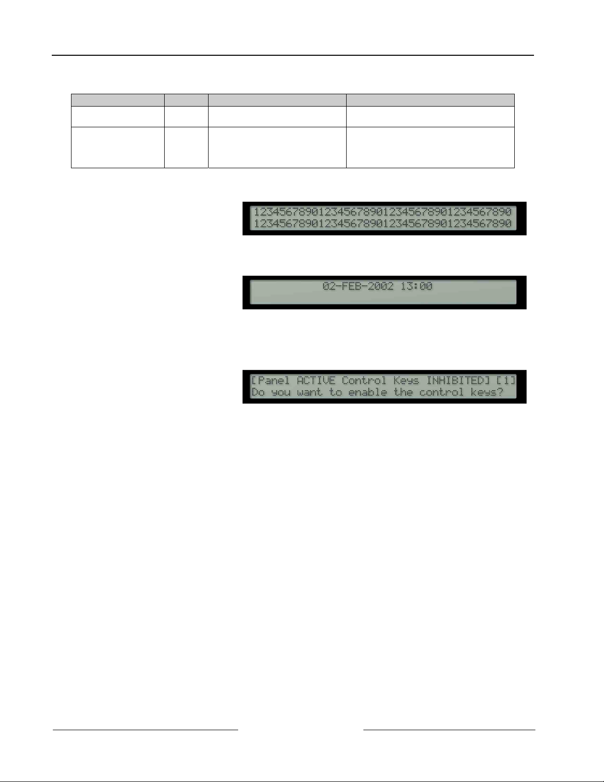
3.1.5 LCD Display Indications
• The alphanumeric liquid
crystal display gives 80
characters of information on a
2-line display. The display is
illuminated to assist viewing
under dim ambient light
conditions.
• When the numeric keypad is
not in use, the display will
revert to automatically
scrolling through any fire
alarm or trouble conditions
present on the panel. If there
are no alarm or trouble
conditions, the display will
show the date and time.
• Pressing the SHIFT key will
show a list of optional
functions or prompt for the
level 2 password.
Red FLASHING: The zone is in a fire
Yellow FLASHING: The zone contains
alarm condition.
faulty devices.
STEADY: The zone is either
disabled or in test mode.
Table 5: Zone LED Functions
Figure 6: LCD Display – 80 characters on 2 lines
Figure 7: Normal Display – Date and Time
Figure 8: Enable Control Keys?
Correct the alarm condition and then perform
a panel reset.
Correct the trouble condition and then
perform a panel reset.
Re-enable devices or cancel test mode.
D8024/D10024A User Manual
50618B Page 12 © 2002 Radionics
Page 13

4.0 Level 1 Display Functions
• At Level 1, the panel operates in a display only mode with the control keys disabled.
• If fire alarm or trouble conditions exist, these will be shown by the LED Indicators and detailed information
will be scrolled on the alphanumeric display.
• The information on the alphanumeric display can be scrolled manually by pressing either the > (forward) or
the < (back) keys.
4.1 Normal Conditions
• When the system is in a normal condition, the green AC Power LED will be illuminated. The alphanumeric
display will show the time and date and will alternate between a user programmed text message and a
system status message.
4.2 Power Fail Conditions
• If the AC power source is interrupted, the AC Power LED will flash and the panel buzzer will sound.
• The back light illumination of the alphanumeric display will be turned off and the display will show an “AC
Fail” message.
• If both the AC input and the Battery Standby Input fail then all LED and alphanumeric display indicators will
be off.
4.3 Fire Alarm Conditions
• If the control panel initiates an alarm condition, the ALARM LED Indicators will be illuminated and, if
appropriate, the relevant ZONE ALARM LED Indicators will flash. The internal buzzer will sound and the
alphanumeric display will give detailed information regarding the fire alarm location.
• If more than one fire alarm condition is present, the alphanumeric display will either automatically scroll
through or, can be manually scrolled through, the fire alarms registered.
4.4 Trouble Conditions
• If the panel detects a trouble, the SYSTEM TROUBLE LED is illuminated along with other appropriate
system condition LED Indicators. The alphanumeric display gives detailed information regarding the nature
of the trouble and the panel buzzer will sound.
• If more than one trouble condition is present, the alphanumeric display will either automatically scroll
through or, can be manually scrolled through, the troubles registered.
D8024/D10024A
Level 1 Display Functions
D8024/D10024A User Manual
© 2002 Radionics Page 13 50618B
Page 14

D8024/D10024A
Level 1 Display Functions
Notes:
D8024/D10024A User Manual
50618B Page 14 © 2002 Radionics
Page 15
D8024/D10024A
Level 2 Control Functions
5.0 Level 2 Control Functions
• All of the functions and operational features described for Level 1 user are available and are the same for a
Level 2 user.
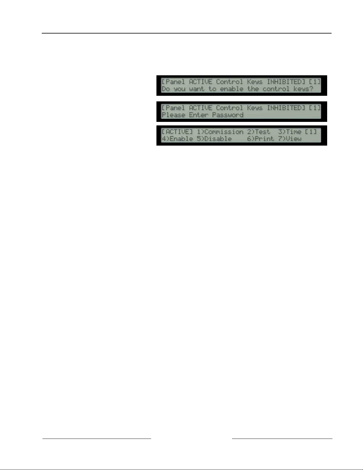
• To enable Level 2 or Level 3
operation, press the SHIFT
key. The display will then
show:
• Press the YES key and the
display will prompt for entry of
the password.
• Enter the 4-digit Level 2
password. The display then
shows the Main Menu of user
options.
• If a key has not been pressed for a certain period, the display will revert to the normal Level 1 display
showing the system status message. To re-show the menu display, press the SHIFT key.
• If a key has not been pressed for a specified period of time, (normally 5 minutes – programmable), then
Level 2 access will be automatically canceled. It will be necessary to re-enter the password to re-activate
Level 2 functions.
5.1 Power Failure Condition
5.1.1 Power Failure Indication
• If the AC input is interrupted, the AC Power LED will flash and the panel buzzer will sound.
• The back light illumination of the alphanumeric display will be turned off. If the power failure lasts longer than
one minute (programmable) the trouble condition will be latched and the display will show an “AC Fail”
message.
• If the AC input returns before the one minute time has elapsed, the panel will return to normal operation, the
AC Power LED will return to ON (Steady) and the buzzer will be automatically silenced.
• If both the AC input and the Battery Standby Input fail then all LED and alphanumeric display indicators will
be off.
5.1.2 User Actions
• To silence the panel buzzer, press the TROUBLE SILENCE key. (
Note: The buzzer will continue to briefly sound about once every 4 to 5 seconds to indicate continued loss of
AC Power.
• When the AC is restored, the AC Power LED returns to steady on and the alphanumeric display returns to
normal.
• To clear the latched AC Trouble, press the SYSTEM RESET key.
5.2 Trouble Conditions
5.2.1 Trouble Indication
• If the panel detects a trouble, the SYSTEM TROUBLE LED is illuminated along with other appropriate
system condition LED Indicators. The alphanumeric display gives detailed information regarding the nature
of the trouble and the panel buzzer will sound.
5.2.2 User Actions
• To acknowledge the event and to silence the panel buzzer, press the TROUBLE SILENCE key. The
TROUBLE SILENCE LED will then be illuminated.
• The panel will not allow a reset until the source of the trouble is corrected. If necessary, the panel allows the
disabling of individual points and zones.
• After correcting the problem, press the RESET key. The SYSTEM TROUBLE, TROUBLE SILENCE and
other appropriate system status LED Indicators will be turned off. The alphanumeric display returns to
normal.
D8024/D10024A User Manual
© 2002 Radionics Page 15 50618B
Page 16
D8024/D10024A
Level 2 Control Functions
5.3 Fire Alarm Conditions
• The panel will indicate a fire alarm condition if it detects an alarm condition of if the FIRE DRILL key is
pressed.
5.3.1 Fire Alarm Indications
• If the control panel initiates an alarm condition, the ALARM LED Indicator will be illuminated and, if
appropriate, the relevant ZONE ALARM LED Indicators will flash. The internal buzzer will sound and the
alphanumeric display will give detailed information regarding the fire alarm location.
• To test the alarm system, or to evacuate the building, press the FIRE DRILL key. The panel will activate all
the NAC output circuits, will illuminate the ALARM LED Indicator and the alphanumeric display will indicate
a ‘Fire Drill’.
5.3.2 User Actions
• Press the TROUBLE SILENCE key to acknowledge the event and to turn off the internal buzzer. The
TROUBLE SILENCED LED is turned on.
• Press the ALARM SILENCE key to silence the NAC output circuits. The SOUNDERS SILENCED LED is
turned on. Press the ALARM SILENCE key again to reactivate the NAC outputs.
• Press the SYSTEM RESET key to reset the system.
5.4 User Option Functions
• The optional functions
available to the user at Level
2 are shown in Table 6.
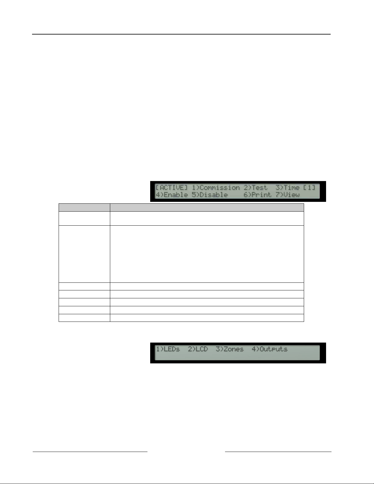
5.4.1 Test
• To display the Test Menu,
• The test menu allows the user to test:
Function Description
Commission This option is not available to Level 2 users. It requires the entry of the Level
3 password before the programming mode can be entered.
Test Allows the user to test parts of the system. The following tests can be
performed:
LED To test the LED indicator lamps. This test will automatically test
each zone indicator and then terminate.
LCD To test the alphanumeric display.
ZONES To perform a ‘Walk Test’ on one or more zones.
OUTPUTS To test the relay and NAC outputs connected to the
system. This test is only available to Level 3 users.
Time To change the date and time in the panel.
Enable To enable zones, inputs, outputs, keys and day mode operation.
Disable To disable zones, inputs, outputs, keys and day mode operation.
Print To print various reports on an internal or remote printer.
View To view devices and system status conditions.
Table 6: User Menu Options
press [2] and the display
shows:
- The LEDs on the front panel display
- The alphanumeric (liquid crystal) display
- The detection and alarm initiating devices connected to the signaling loop.
- The NAC outputs and other alarm condition output devices connected to the system
D8024/D10024A User Manual
50618B Page 16 © 2002 Radionics
Page 17
5.4.1.1 LEDs Test
• To select the option, press [1].
• To terminate the test, press [No].
• The panel will flash all of the indicators on the LED Display and will step through all the Zone ALARM and
TROUBLE indicators.
5.4.1.2 LCD Test
• To select the option, press [2].
• To terminate the test, press [No].
• The alphanumeric display will flash all displayable characters in all positions of the display and then return to
the menu.
5.4.1.3 Zones Test
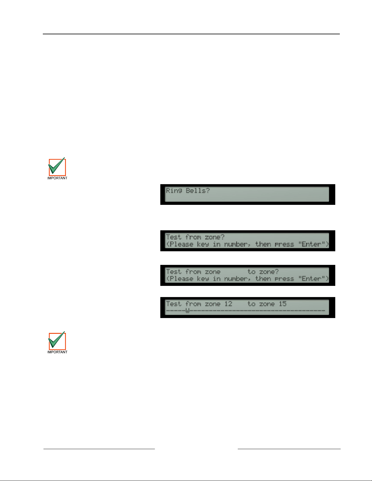
• The ‘Walk Test’ option allows the user to conveniently test the detection and alarm initiating devices without
having to continually reset the panel.
• To select the option, press [3].
If no action is taken at this point, the display will automatically revert to the normal display after 1
minute. Pressing SHIFT or > will return the display to the test display.
• The display will then prompt
for whether the NAC outputs
should ring:
D8024/D10024A
Level 2 Control Functions
• Press [Yes] and the NACs (dependent on their programming) will ring for a few seconds and then be reset
automatically when a device is tested.
• Press [No] and the NACs will not ring.
• The panel can be set to test a
range of zones. The display
will prompt for the first zone to
be tested:
• Key in the number of the first zone to be tested. For example, for zone 12, press [1]+[2]+[Enter].
• The display then prompts the
last zone to be tested:
• Key in the number of the last zone to be tested. For example, for zone 15, press ‘15 ENTER’.
• the bottom line:
When the display indicates that the panel is in ‘Walk Test’, the display will continue to show that
walk test mode is active. If there is no activity for 20 minutes, the panel will terminate the test.
• In the above example, any detector or initiating device going into alarm condition in zones 12, 13, 14 or 15
will:
- Display an activation message on the alphanumeric display, write the event in the event log, sound the
panel buzzer and illuminate the appropriate zone ALARM LED.
- Turn on the LED at the sensor that initiated the alarm
- After a few seconds, the panel will be automatically be reset and the detector LED turned off. The panel
is then ready to test the next detector. (Note: Up to one minute is allowed for smoke detectors to clear).
• If an alarm signal is received from a zone other than those under test, then all NAC output and relay output
circuits will activate as programmed for the zone in alarm. The NACs will continue to ring until silenced from
the panel.
• Press [No] to terminate the walk test.
D8024/D10024A User Manual
© 2002 Radionics Page 17 50618B
Page 18
D8024/D10024A
Level 2 Control Functions
5.4.1.4 Output Test
Access to this test option is only available to users with the Level 3 password.
• To select the option, press [4] and then enter the password ‘####’.
• To terminate the test, press [No].
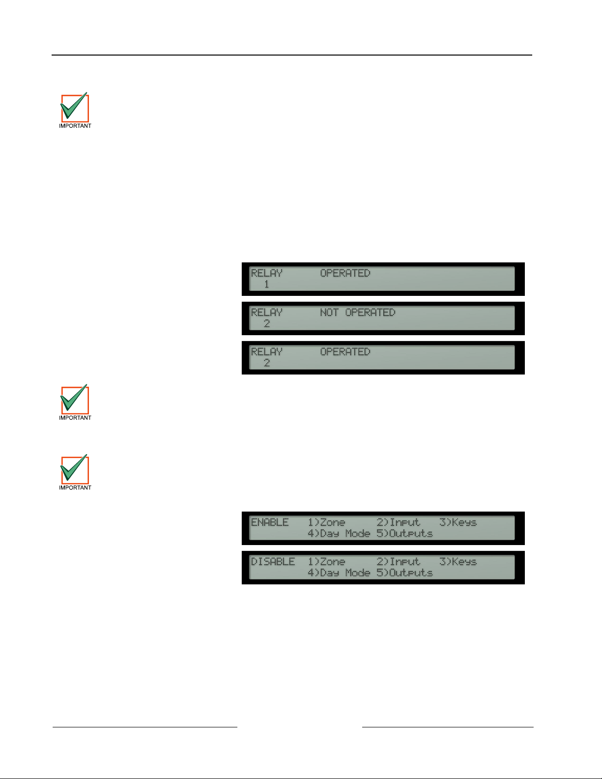
• The output test allows the relays and NACs to be individually operated. The first six outputs are reserved for
the panel’s own onboard relay and NAC circuits as shown below:
- Output 1 – Onboard Relay 1
- Output 2 – Onboard Relay 2
- Output 3 – Onboard NAC A
- Output 4 – Onboard NAC B
- Output 5 – Onboard NAC C (Not available on D8024 panel!)
- Output 6 – Onboard NAC D (Not available on D8024 panel!)
• On entering the test, the
display will show the current
state of the first output:
• To advance to the next
output, press the [>] or the
[Yes] key.
• To change the output state,
press the [Change] key. The
display will show the new
state:
The onboard NAC circuits are constantly monitored for correct end-of-line termination. A NAC error
will be reported if one of the NACs is left in the operated test state for more than 5 seconds.
5.4.1.5 Time
• To change the date and time shown on the alphanumeric display, press [3] from the main user option menu.
On multi-panel systems, it is only necessary to change the time at the Master Panel. All of the other
panels will synchronize their date and time to that of the master panel when a reset is performed on
5.4.1.6 Enable / Disable Functions
the master panel.
• To select the enable or
disable menu options, press
[4] or press [5] as required
from the user main menu.
The display shows for each
option:
• The options available in each menu are identical. This allows the user to enable or disable:
- Zones
- Individual devices
- Panel Keys
- Day Modes
- Outputs (NACs or relays)
5.4.1.7 Enable or Disable Zones
• To enable or disable input devices by zone, select option 1.
D8024/D10024A User Manual
50618B Page 18 © 2002 Radionics
Page 19
Any loop driven output devices such as NACs or relay modules will still activate as programmed
even if disabled. Only the input signal from these devices will be ignored.
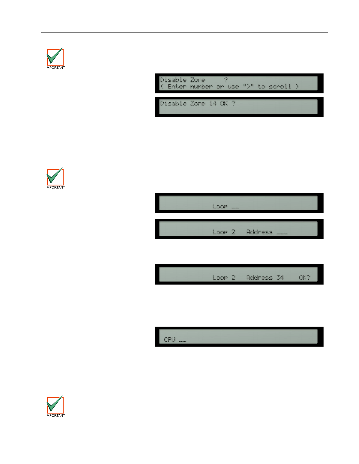
• Press [1] and the display will
prompt for the required zone
number.
• Key in the zone number and
then press the [ENTER] key.
Or use the [>] key to scroll
through the zones.
• The display will then repeat the zone number and ask for confirmation (OK?). Press the [Yes] key to confirm.
• The panel will enable or disable the input devices in the zone.
• When a zone is disabled, the POINT BYPASSED LED and the corresponding yellow Zone TROUBLE LED
will be illuminated.
5.4.1.8 Enable or Disable Inputs
• To enable or disable individual input devices, select option 2.
Any loop driven output devices such as NACs or relay modules will still activate as programmed
even if disabled. Only the input signal from these devices will be ignored.
• Press [2] and the display will
prompt for the signaling loop
circuit number where the
device is located.
• Enter the required loop
number (1-2 for D8024 or 1-5
for D10024A) and the display
will prompt for the numeric
address of the device:
• Enter the address of the device required. If the address is less than 3-digits long (for example address 34),
this can be entered as either [0]+[3]+[4] or [3]+[4] followed by [Enter].
• The display will then ask for
confirmation (OK?).
D8024/D10024A
Level 2 Control Functions
• Press the [Yes] key to confirm.
• When an individual point is disabled, the POINT BYPASSED LED will be illuminated.
• The corresponding Zone TROUBLE LED will only be illuminated if all devices in the zone are disabled.
5.4.1.9 Networked Panels
• Master panels are able to command other panels to enable or disable individual devices.
• In this case, the display will
prompt with an additional,
opening question requesting
the panel (CPU) number.
• Enter the address of the required panel. The display will then prompt for the loop and device address
information as described above.
5.4.1.10 Enable or Disable Keys
• To disable the panel control keys, press [3] from the disable menu.
• The user Level 2 password will then be required to re-enable the panel control keys and provide access to
the User Option Functions.
The panel keys will be automatically disabled if a key has not been pressed for a pre-programmed
period.
D8024/D10024A User Manual
© 2002 Radionics Page 19 50618B
Page 20
D8024/D10024A
Level 2 Control Functions
5.4.1.11 Enable or Disable Delayed Day Modes
• The Delayed Day Mode operation is configured at Level 3 by the installer / maintenance contractor. The
Delayed Day Mode causes the panel to respond to high sensor signals by sounding the panel buzzer and
displaying a warning message on the alphanumeric display. The panel delays the activation of the alarm
condition outputs (NACs or relays) for a programmed period.
• The user may enable or disable the operation of the Delayed Day Mode through the Enable or Disable
Menus.
• To select Delayed Day Mode, press [4] from the Enable or Disable Menus.
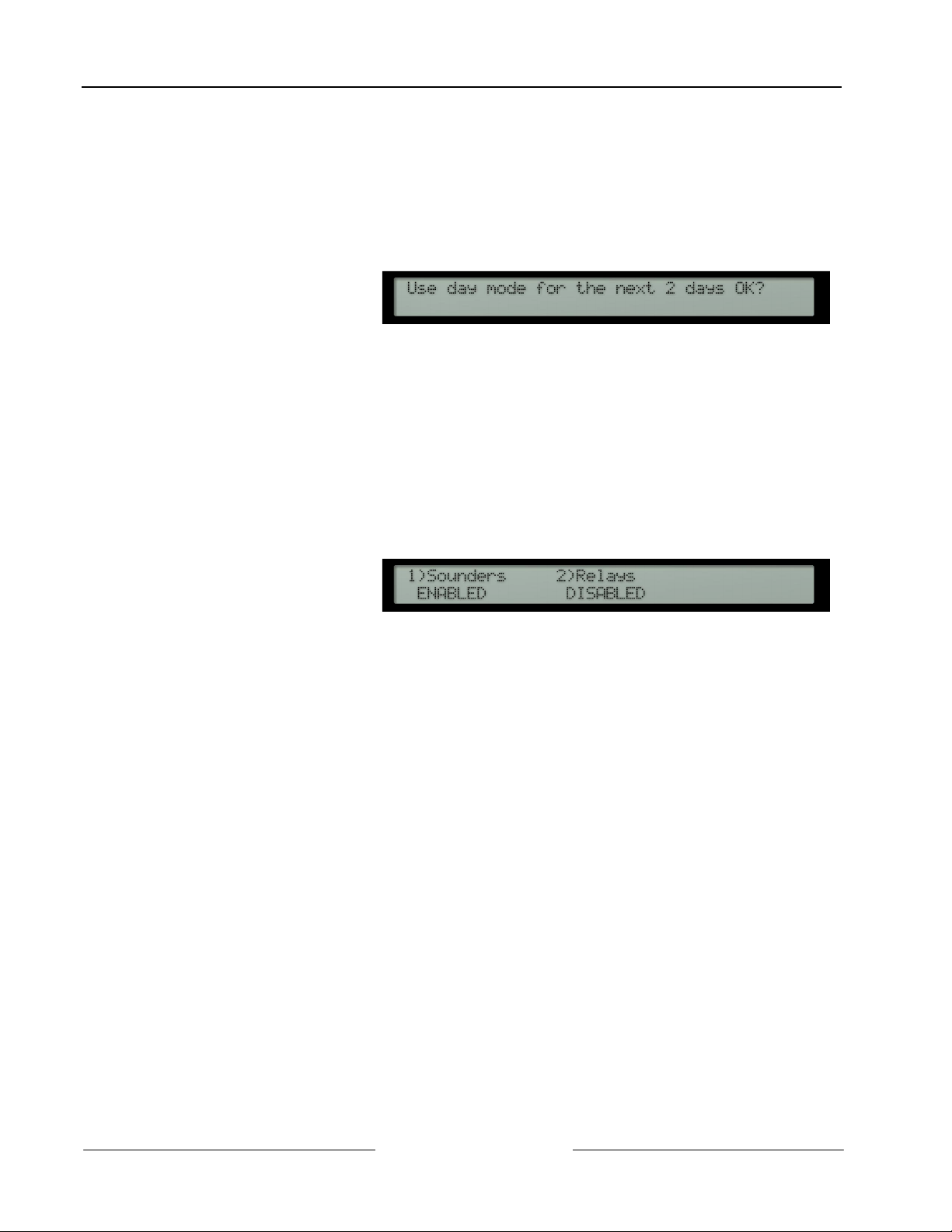
• When enabling the operation
of the Delayed Day Mode
function, the display prompts
for the number of days the
Delayed Day Mode is to be in
operation.
• If the prompted number of days is not as required, press the [Change] key and then enter the required
number of days.
• In the above example, the Delayed Day Mode will be effective for today and tomorrow. The day after
tomorrow, the panel will go immediately into a full fire alarm condition on receiving a high signal from a
device.
• The number of days can be selected in the range 001 to 199. To permanently enable the Delayed Day
Mode operation, enter the number of days as 200.
5.4.1.12 Enable or Disable Outputs
• All output devices (i.e. NACs and relays) can be disabled or enabled for test purposes.
• To enable or disable an output device, press [5] from the enable or disable menus.
• The display then shows a
menu of the devices available
and their current enable /
disable status:
• The POINT BYPASSED and either the SOUNDERS DISABLED or RELAYS BYPASSED LED indicators will
be illuminated when the outputs are disabled. A warning message will also be shown on the alphanumeric
display.
• The NACs can only be disabled after confirmation by re-entering the Level 2 password.
D8024/D10024A User Manual
50618B Page 20 © 2002 Radionics
Page 21
D8024/D10024A
Level 2 Control Functions
5.4.1.13 Print
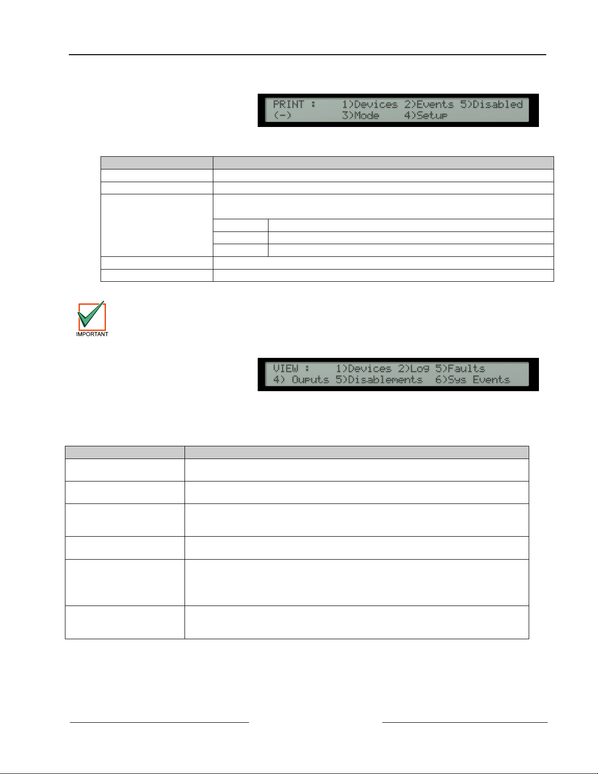
• To select the print menu,
press [6] from the user main,
option menu. The display
then shows:
• This menu controls the operation of the optional front panel printer on the D10024A panel only. The user
options are as follows:
Options Description
Devices prints out the present status and text assigned to all devices on a loop.
Events prints out the contents of the event log.
Mode
Setup sets the type of printer connected to the panel.
Disabled prints a list of all disabled devices.
The printer Setup option can only be performed at Level 3 by an installer / maintenance contractor.
5.4.2 View
• To select the view menu,
press [7] from the user main,
option menu. The display
then shows:
• This menu allows the user to view information about the selected option on the alphanumeric display.
• After viewing an option, press [No] to return to the view menu. From the view menu, press [No] to return to
the main options menu.
• The following View Mode Options are available:
View Option Description of Function
Devices Displays the status and text of anyone detector on a signaling loop. The panel
Log Displays the contents of the event log. Events can be scrolled forwards or backwards
Faults Displays the current panel fault status. The display is identical to the automatic
Outputs Displays the required state of all output (NAC and relay) devices. Pressing the
Disablements Displays a sub menu from which the following can be selected
Sys Events The top line of the display shows the event number (1 – 200). The bottom line,
sets the printing mode. The current mode of operation is shown on the display.
The possible modes are:
Manual prints on demand only
Auto automatically prints troubles and fire alarms as they occur
- the printer is turned off
Table 7: Print Options
prompts for the loop number and device address.
using the [>] or [<] keys.
trouble / fire alarm display, but with the ability to manually scroll through all the
troubles using the [>] and [<] keys.
[
Silence / Resound
1) Zones- Allows all zones that are in either a full or a partial state of disablement, to
be viewed.
2) Inputs- Allows viewing of all inputs that are disabled.
immediately beneath the event number, shows whether the event is present (+) for
non latched events, (*) for latched events or (-) for inactive events.
] key turns all NACs to an off condition.
Table 8: View Mode Options
D8024/D10024A User Manual
© 2002 Radionics Page 21 50618B
Page 22

D8024/D10024A
Level 2 Control Functions
Notes:
D8024/D10024A User Manual
50618B Page 22 © 2002 Radionics
Page 23

6.0 Delayed Day Mode Operation
• The panel can be configured to operate in a delayed day mode during the daytime for any specified zone.
• During this time, high sensor signals received from a detector will generate a fire alarm message on the
panel but delay the ringing of the NACs. The panel will initiate a full fire alarm condition if no action is taken
on this warning within a specified period.
• The use of delayed day mode must be configured at Level 3 by an installer / maintenance contractor before
it is available for use at Level 2.
• The delayed day mode can be configured to only operate at specified times of the day and only in specified
zones if required. The maximum time allowed to acknowledge stage 1 and stage 2 times can be
programmed in intervals of one second.
6.1 Stage 1
• When a fire alarm condition is detected during delayed day mode, the internal buzzer will sound. The sensor
location will be shown on the display along with a warning that the panel has entered stage 1 of a delayed
alarm.
• If the warning is not acknowledged, by pressing [
then a full fire alarm condition will be raised and the NAC outputs will activate.
• Pressing [
6.2 Stage 2
• The stage 2 timer commences counting down as soon as the panel receives the initial high signal from the
detector. (i.e. it commences at the same time a stage 1 begins).
• Setting the stage 2 timer to a longer period than the stage 1 timer will allow the user to investigate the cause
of the alarm and take appropriate action.
• If the panel is not reset, using the [
will be raised and the NAC outputs will activate.
Silence / Resound
] within the time allowed will cause stage 2 of the delayed alarm.
System Reset
D8024/D10024A
Delayed Day Mode Operation
Silence / Resound
] key, within the time allowed then a full fire alarm condition
], within the time allowed for stage 1,
Manual Stations will always generate an immediate fire alarm condition regardless of an delayed
day mode settings.
D8024/D10024A User Manual
© 2002 Radionics Page 23 50618B
Page 24

D8024/D10024A
Delayed Day Mode Operation
Notes:
D8024/D10024A User Manual
50618B Page 24 © 2002 Radionics
Page 25

7.0 Level 3 Programmer Functions
D8024/D10024A
Level 3 Programmer Functions
Refer to the
commissioning and programming the D8024 and D10024A Fire Alarm Control Panels.
D8024/D10024A Operation and Installation Manual
(PN 50616) for complete information on
D8024/D10024A User Manual
© 2002 Radionics Page 25 50618B
Page 26

D8024/D10024A
Level 3 Programmer Functions
Notes:
D8024/D10024A User Manual
50618B Page 26 © 2002 Radionics
Page 27
8.0 Log Book
• In accordance with best practice, the user should maintain a logbook to record all events resulting from or
affecting the system. The logbook should be kept in a place accessible to authorized persons (preferably
near the main panel.
• One or more identifiable individuals should be appointed to oversee or carry out all entries in the logbook.
The names of the persons (and any changes of responsible person) should be recorded.
• All events should be properly recorded (events include real and false fire alarms, troubles, pre-alarm
warnings, tests, temporary disconnection’s and service visits). A brief note of any work carried out or
outstanding should be made.
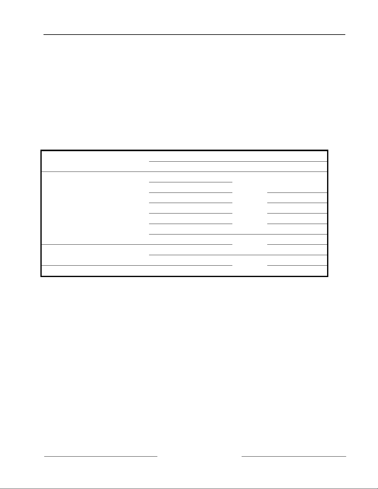
• Sample pages of the logbook are provided here and can be photocopied to produce a suitable logbook. The
sample below is for reference data (e.g. the name of the responsible person), while the sample on the next
page is for the entry of event information.
8.1 REFERENCE DATA
Site Name and Address:
Site Telephone Number:
Responsible Person: Date
The system was installed by:
And is maintained under contract by:
Contact Telephone Number: If Service is Required.
D8024/D10024A
Log Book
Date
Date
Date
Date
Until
Table 9: Logbook Reference Data
D8024/D10024A User Manual
© 2002 Radionics Page 27 50618B
Page 28
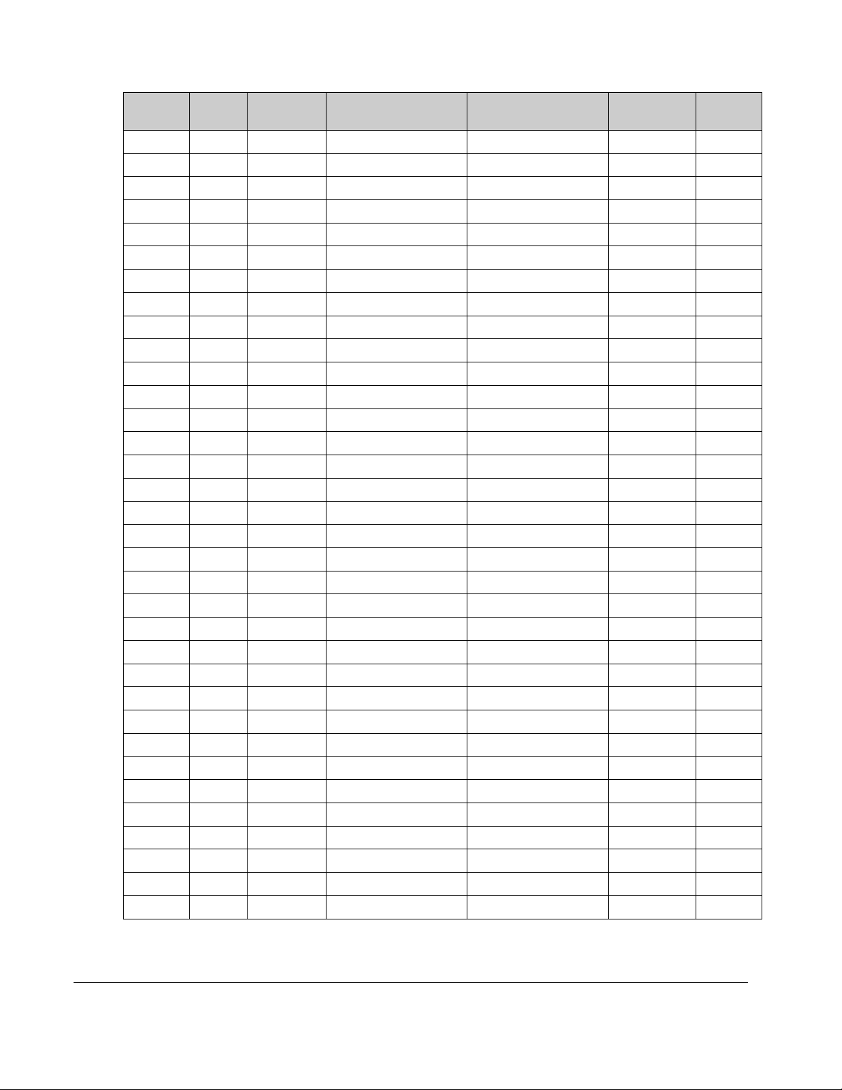
8.2 EVENT DATA
Date Time Counter
Reading
Event Action Required Date
Completed
Initials
Table 10: Logbook Event Data
© 2002 Radionics, a division of Detection Systems, Inc.
PO Box 80012, Salinas, CA 93912-0012, USA
Customer Service: (800) 538-5807
50618B
User Manual
7/02
D8024/D10024A
Page 28 of 28
 Loading...