

Page 1

P/N 35110 8/11/97 1997 Radionics
™
Radionics
D2000 Series
Keypad Diagnostics
Putting the Keypad into the Diagnostics
Mode
The panel sends SERVICE START and SERVICE
END messages upon entering and exiting
Diagnostics Mode.
1. Lock the Standby Switch down.
2. Press the [1] key on the keypad.
3. Enter your “Installer” passcode. The default
Installer passcode is 6 5 4 3 2 1. The default
passcode length is three, so if you have not
changed the default entries, press 6 5 4.
If the passcode you’ve entered is valid, the
keypad’s display scrolls the functions that are
available.
Now that you’re in...
When you select a function, the system displays
messages informing you of test status. Once inside
a function, press the [Clear] key to return to the
previous level.
Bell Test
The Bell Test powers the external bell with the
burglar pattern for 2 seconds.
• Press the [1] key. The display shows:
TESTING BELL
The Bell Test times out after 2 seconds.
Page 2

2
Battery Test
The Battery Test causes the panel to run on the
battery only, for 4 minutes. During this time, if the
voltage drops below 12.2, the trouble tone sounds
and the low battery condition appears in the Check
System mode (Key 4).
When the Battery Test is started, a Low Battery
report or a Missing Battery report will be sent, if
programmed.
• Press the [2] key. The display shows:
TESTING BATTERY
MAY TAKE 4 MIN.
The test times out in approximately 4 minutes, and
the results are displayed. If the battery is good, the
display shows:
BATTERY TEST
PASSED
Press the [Clear] key to return to the main menu.
If the battery is bad, the display shows:
BATTERY TEST
FAILED
Press the [Clear] key to return to the main menu.
Communication Test
The Communication Test sends a test report to the
receiver. If the report fails to be acknowledged after
all dialing attempts, the panel goes into
Communications Failure.
• Press the [3] key. The display shows :
TESTING PHONE
MAY TAKE 10 MIN.
Page 3

3
The test times out in approximately 10 minutes,
and the results are displayed. If the phone line is
good, the display shows:
PHONE TEST
PASSED
Press the [Clear] key to return to the main menu. If
the phone line is bad, the display shows:
PHONE TEST
FAILED
Press the [Clear] key to return to the main menu.
RF Programming
Before RF Points can be learned, the D208
Receiver must be connected to the panel and
powered.
It is possible to encounter RF receiver errors when
attempting these operations. An example would be
programming the point code for point 10 as an RF
point using a receiver on address 8, when there is
no receiver connected to address 8. When you
attempt to learn point 10, the system will be unable
to communicate to a receiver. In this event, you’ll
see the display:
NO REPLY RCVR 8
PRESS CLEAR
After pressing the [Clear] key, the display will return
to the RF menu.
1. Press the [4] key to display the RF
programming menu.
2. The display scrolls the three RF menu options:
Page 4

4
TO LEARN POINTS
PRESS 1
TO TEST POINTS
PRESS 2
TO REMOVE POINTS
PRESS 3
3. To exit the RF Programming menu and return
to the diagnostics menu, press the [Clear] key.
Learning RF Points
To learn a point, you must have previously given it
an RF point code (digits 4 and 5).
1. In the RF menu, press (1) to Learn Points. If
there are unlearned points whose point codes
have been programmed as RF, the keypad
displays the first one to be learned (in this
example, point 1 is the first point programmed
as an RF point):
LEARN POINT 1
PRESS *
To scroll the remaining RF points, press the [C] key
repeatedly. If there is only one RF point, it will be
continually re-displayed.
If there are no points programmed as RF points, or
all programmed points have already been learned,
the display shows the following.
NO POINTS TO LEARN!
PRESS CLEAR
After pressing the [Clear] key, the system returns to
the RF menu.
2. Press the [*] key to select the point displayed.
The display shows:
ACTIVATE
Page 5

5
POINT 1
3. Press the tamper switch on the sensor you
want to learn as point 1. When the
transmission is received, the point is learned
and the display shows:
POINT 1 LEARNED
PRESS CLEAR
If the sensor has already been learned into some
other point, or two points were inadvertently
programmed to the same sensor loop, the display
shows the following (in this example, the sensor
had previously been learned as point 2, although it
could be any point number):
DUPLICATES PT 2
PRESS CLEAR
Press the [Clear] key and repeat the procedure
using a sensor that hasn’t already been learned, or
check point programming making sure that two
points were not assigned to the same location (see
digit 4 and 5 of point code).
4. Pressing the [Clear] key returns the display to
the next RF point to be learned:
LEARN POINT 2
PRESS *
5. Pressing the [Clear] key again returns the
display to the RF menu.
Testing RF Points
To test a point, it must have been learned.
1. In the RF menu, press (2) to Test Points. If
there are RF points which have been learned,
the first one will be shown.
TEST POINT 1
PRESS *
Page 6

6
To scroll the remaining learned points, press the
[C] key repeatedly. If there is only one learned
point, it will be continually re-displayed.
If no RF points have been learned, the display
shows the following:
NO PTS LEARNED!
PRESS CLEAR
2. Press the [*] key to select the point displayed.
The display shows:
TESTING POINT 1
ROUNDS: 00
3. To begin the test, trip the sensor on the point
you’re testing (in this case, point 1), and listen
for and count the beeps from the keypad. The
beeps indicate rounds of data sent from the
sensor when tripped. Each sensor sends 8
rounds per each trip. The counter next to the
word “ROUNDS” is incremented once for each
round received.
4. The number of rounds (beeps) can be used to
determine whether a sensor is in a good
location or not. Intrusion and other types of
sensors (doors/window, shock, PIR & sound
sensors, smoke/heat sensors, portable panics)
have the following validation:
7 to 8 rounds = Acceptable
6 or fewer rounds = Poor or Unacceptable
The testing procedure is slightly different for RF
keypads. Rather than relying on the count of
rounds transmitted, position the keypad where it
will likely be used, and press any key. If you hear a
beep, and the function associated with the key is
performed by the panel, the location is a suitable
one for keypad operation.
5. Pressing the [Clear] key ends the test and
returns the display to the next point to be
tested (if any):
Page 7

7
TEST POINT 2
PRESS *
6. Pressing the [Clear] key again returns the
display to the RF menu.
Removing RF Points
To remove a point, it must have previously been
learned.
1. In the RF menu, press (3) to Remove Points. If
there are RF points which have been learned,
the first one will appear in the display (in this
example, point 1 is the first point programmed
as an RF point):
REMOVE POINT 1
PRESS *
To scroll the remaining learned points, press the
[C] key repeatedly. If there is only one RF point, it
will be continually re-displayed.
If there are no learned RF points, the display shows
the following.
NO PTS LEARNED!
PRESS CLEAR
After pressing the [Clear] key, the system returns to
the RF menu.
2. Pressing the [*] key removes the point
displayed. The display shows:
POINT 1 REMOVED
PRESS CLEAR
3. If the [Clear] key is pressed and there are more
learned RF points, the display shows the next
learned point:
Page 8

8
REMOVE POINT 2
PRESS *
You can continue to remove as many learned RF
points as you want.
4. If there are no more learned RF points, the
display shows:
NO PTS LEARNED!
PRESS CLEAR
Pressing the [Clear] key returns the display to the
RF menu.
5. When you’ve finished removing points, press
the [Clear] key to return to the RF menu.
Point Status
The Point Status function displays the electrical
state of all points. The state of each point is shown
in the system’s display. Points that are not
programmed are displayed as normal.
1. Press the [5] key. The display shows the status
of points 1 and 2:
POINT 1 NORMAL
POINT 2 OPEN
2. Press the [*] key repeatedly to scroll the
remaining points. Points may be Normal,
Open, or Short:
POINT 3 SHORT
POINT 4 OPEN
3. Press the [Clear] key to exit this test.
Relays
The Relays function can activate either of the two
external relay outputs.
Page 9

9
1. Press the [6] key to enter the Relays function.
2. Hold the [1] key to turn on relay 1. The relay
stays on as long as key 1 is held down. Follow
the same procedure to test relay 2.
3. Press the [Clear] key to exit this test.
Power Supply Status*
The Power Supply Status function performs four
different tests on the power supply and battery.
Obtained readings are + or - 200mA / 200mV.
1. Press the [7] key. The display shows:
POWER SUPPLY*
...To display Fire Alarm Load
2. Disconnect the battery.
3. Press the [1] key.
The bell and external relays activate and the
display shows:
FIRE ALARM LOAD
LESS THAN ### MA
4. Use the scale on the following page to verify
that the current consumption is less than
860mA:
* Some panels do not include the Power Supply Status
function.
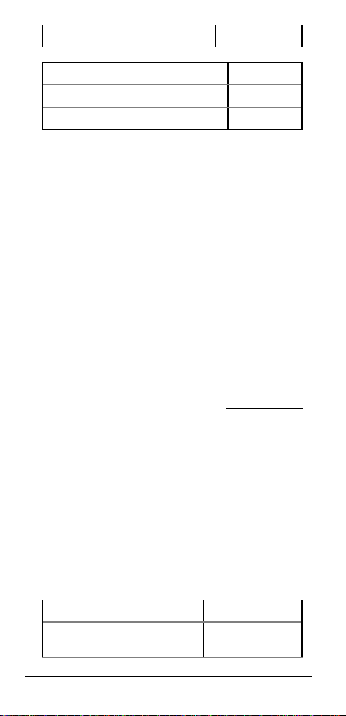
Maximum Fire Alarm Load 860mA
732mA
605mA
Page 10
10
477mA
Max Normal Supervisory Load 350mA
222mA
95mA
5. If current consumption is more than 860mA,
the display will show:
FIRE ALARM LOAD
MORE THAN 860 MA
6. Press the [Clear] key.
7. Reconnect the battery.
...To display the Minimum Battery Voltage
2. Make sure the battery is connected.
3. Press the [2] key.
The panel automatically disconnects AC, and the
display shows the lowest battery voltage during the
test and gives an acknowledge tone after 1 minute:
MIN BATT VOLTAGE
##.# VOLTS
4. Verify that the battery does not drop below
13.2 volts within the minute.
Minimum Battery Voltage
after 1 Minute
13.7 Volts
13.2 Volts
Page 11

11
12.7 Volts
Read Battery Voltage 12.2 Volts
11.7 Volts
11.2 Volts
10.7 Volts
10.2 Volts
5. Press the [Clear] key.
...To Read Battery Voltage
2. Make sure the battery is connected.
3. Press the [4] key. The battery voltage displays:
BATT VOLTAGE
##.# VOLTS
4. Verify that the battery is above 11.7 volts.
5. Press the [Clear] key.
...To display Normal Supervisory Load
2. Disconnect the battery.
3. Press the [5] key. The display shows:
NORMAL LOAD
LESS THAN ##.# AMPS
4. Verify that the current consumption is less than
350mA.
5. Press the [Clear] key.
Page 12

Technical Support: (800) 538-5807
6. Reconnect the battery.
To exit the Power Supply Status function, press the
[Clear] key again.
Programming
Function 8 is the Keypad Programming Mode. For
complete instructions on programming from the
keypad, see the Program Entry Guide.
System Trouble
This diagnostic check is available in the user’s
Check System (Key 4) mode.
1. Press the [Clear] key to exit the Diagnostic
Mode. The display shows:
SYSTEM TROUBLE
PRESS 4 TO VIEW
2. Press the [4] key. The display shows:
CALL FOR SERVICE
3. Press the [5] key. The display scrolls through
the trouble messages:
LOW OR MISSING
BATTERY
STAND-BY SWITCH
LOCKED
AUX PWR TRBL
TERMINAL
BELL PWR TRBL
TERMINAL
RCVR ## TAMPER
RCVR ## TROUBLE
1997 Radionics, Salinas CA. All rights reserved.
The Radionics logo is a registered trademark of Radionics.
Radionics, 1800 Abbott Street, Salinas, CA 93901, USA
Page 13
Users Guides Menu
Documents by Type Menu
Documents by Product Menu
Main Menu
 Loading...