

Seitz Roundshot VR Drive, Roundshot VR Drive s Instruction Manual
Instruction Manual Roundshot VR Drive - version 4.0 – January 2010 - © by Seitz Phototechnik AG / Switzerland www.roundshot.ch page 0
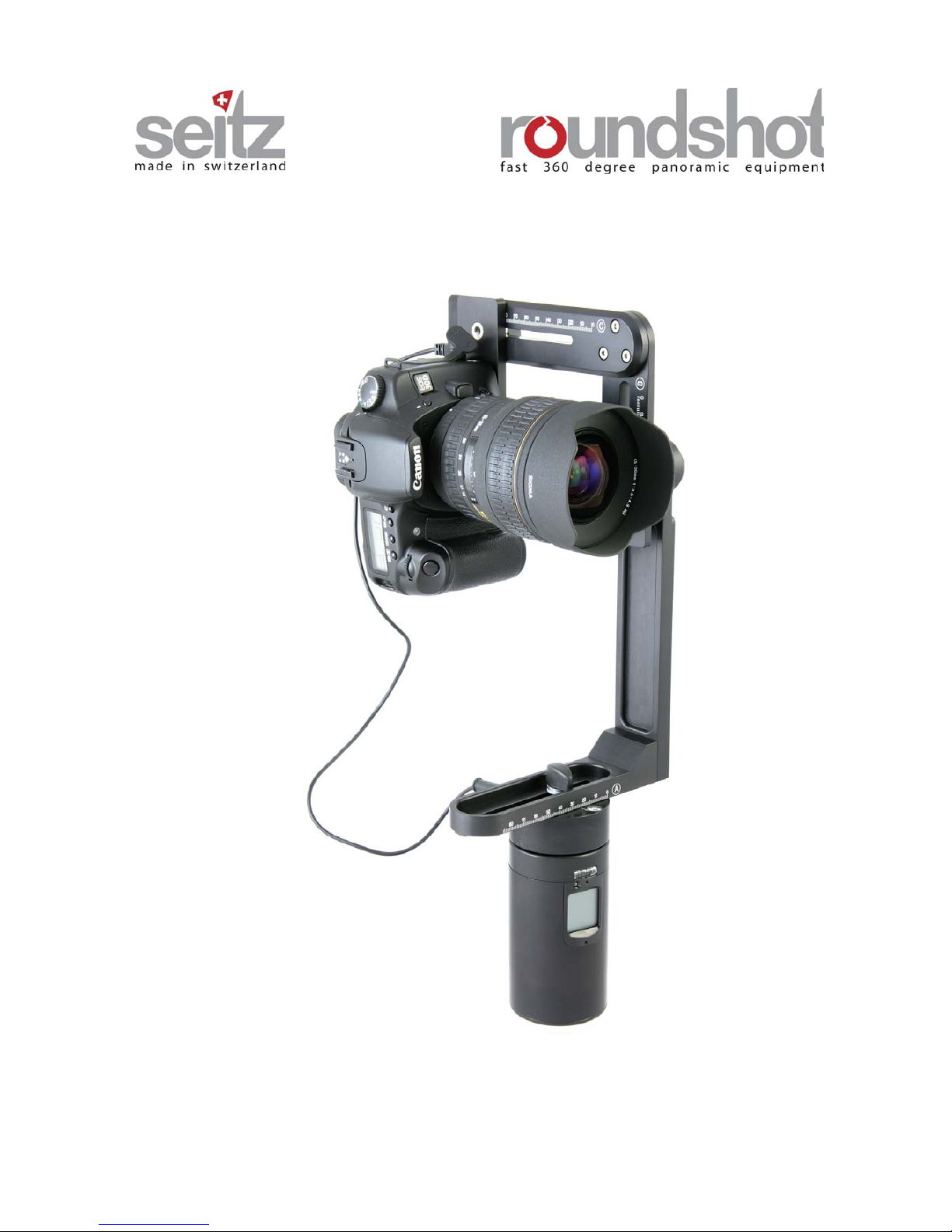
Roundshot VR Drive / Roundshot VR Drive s
Software release: version 4.0 (January 2010)
Instruction Manual
Instruction Manual Roundshot VR Drive - version 4.0 – January 2010 - © by Seitz Phototechnik AG / Switzerland www.roundshot.ch page 1
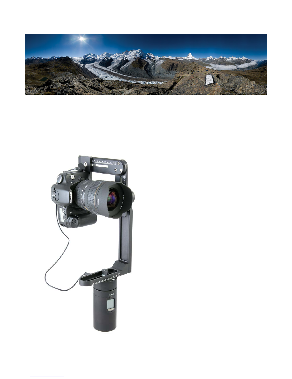
Riffelhorn (2,928 m altitude), Zermatt / Switzerland
180 images taken with digital SLR camera and Roundshot VR Drive, stitched to 1.04 GB panorama (20,900 x 53,743 pixels)
Photographer: Matthias Taugwalder (www.concept360.ch)
This product is available in two versions:
• Roundshot VR Drive
• Roundshot VR Drive s
The Roundshot VR Drive is equipped
with the „quality mode“.
The Roundshot VR Drive s offers both the
„quality mode“ and the „speed mode“.
It is possible to upgrade a VR Drive to the
„s“ version (eprom upgrade) at the Seitz
factory.

Instruction Manual Roundshot VR Drive - version 4.0 – January 2010 - © by Seitz Phototechnik AG / Switzerland www.roundshot.ch page 2
CONTENTS
Page
1. System Overview 3
1.1 Roundshot VR Drive Panorama Set & Object Movie Set 3
1.2 Accessories 4
2. Roundshot VR Drive Panorama Set 5
2.1 Setting up the VR Drive Panorama Set 5
2.2 Cylindrical and spherical panoramas & number of images 10
2.2.1 Cylindrical panoramas 10
2.2.2 Spherical panoramas 11
2.2.3 Number of images to create the panorama 12
2.3 Quality Mode 16
2.3.1 Rotation time (T1) 16
2.3.2 Anti-vibration pause (T2) 16
2.3.3 Time for continuous release (T3) 17
2.3.4 Degrees of panorama 18
2.3.5 Number of images 18
2.3.6 Ramp 19
2.3.7 Repeat 19
2.3.8 Bracketing 20
2.3.9 Timer 21
2.3.10 Manual release 21
2.3.11 Shut down 21
2.4 Speed mode (Roundshot VR Drive s only) 22
2.4.1 Rotation time (T1) 22
2.4.2 Speed mode selection (T2) 23
2.4.3 Release signal time (T3) 23
2.4.4 Degrees of panorama 24
2.4.5 Number of images 24
2.4.6 Repeat 25
2.4.7 Timer 25
2.4.8 Shut down 25
3. Roundshot VR Drive Object Movie Set 26
3.1 Setting up the VR Drive Object Movie Set 26
3.2 Quality Mode 26
4. Maintenance & Warranty 27
4.1 Recharging the VR Drive 27
4.2 Transport & storage 27
4.3 Firmware update 27
4.4 International warranty 28
4.5 Return of equipment / recycling 28
5. Technical Data 29
Instruction Manual Roundshot VR Drive - version 4.0 – January 2010 - © by Seitz Phototechnik AG / Switzerland www.roundshot.ch page 3
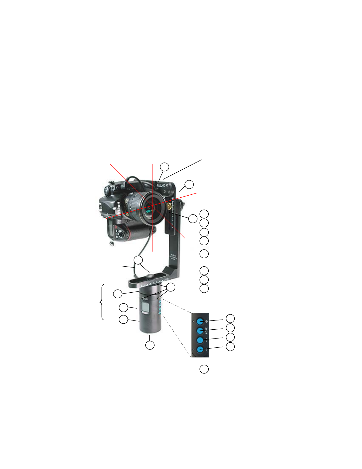
1. System Overview
1.1 Roundshot VR Drive Panorama Set & Object Movie Set
VR Drive
motor with
firmware and
batteries
Digital
camera
3
9
VR Drive bracket / VR Head
9
VR Drive Panorama Set
1
A
B
C
Adjustment bar for x-axis
Adjustment bar for y-axis
Adjustment bar for nodal point
Tilt lever to change z-axis
Y-axis
X-axis
Z-axis
D
Electronic
release
cable
Socket for release cable (panorama
mode)
Spirit level
Display
Socket for release cable (object movie
mode) and for charger cable
Tripod mount (3/8‘‘)
2
5
6
7
8
A
B
C
D
1
3
2
Start/stop button
Mode button
Up button
Down button / power off
4
4

Instruction Manual Roundshot VR Drive - version 4.0 – January 2010 - © by Seitz Phototechnik AG / Switzerland www.roundshot.ch page 4
1.1 Roundshot VR Drive Panorama Set & Object Movie Set (continued)
Fully automatic release of camera,
synchronised with VR Drive
Easy release of the VR Drive if it is in a
higher or inaccessible position.
3 functions:
1. Activate camera from "stand-by"
2. Start camera
3. Stop camera
Ideal for shots in manual mode, when the
VR Drive should not be touched
Practical accessory for precise object
photography (object movies) and for
the scanning of cylindrical objects
(turntable)
Electronic release cable (included in Set)
Between VR Drive
connection (1) and
camera plug
Starter cable (1.6m – other lengths possible)
Into connection for
external release (9)
Turntable set
•Turntableon VR Drive
engine
•Extension cableinto
connection for
external release (9)
and camera plug
VR Drive Object Movie Set
10
Turntable (120mm)
with screw
10
1.2 Accessories

Instruction Manual Roundshot VR Drive - version 4.0 – January 2010 - © by Seitz Phototechnik AG / Switzerland www.roundshot.ch page 5
2. Roundshot VR Drive Panorama Set
2.1 Setting up the VR Drive Panorama Set
TheVR Headcanbeseparatedforeasier
transport:
It can be reassembled in the
following way:
Step 2: Place the VR Drive motor on a tripod
Step 3: Attach the VR Head on top of the VR Drive motor.
Make sure that the VR Head is placed firmly on the VR Drive motor.
Step 1: Assemble the VR Head
Instruction Manual Roundshot VR Drive - version 4.0 – January 2010 - © by Seitz Phototechnik AG / Switzerland www.roundshot.ch page 6
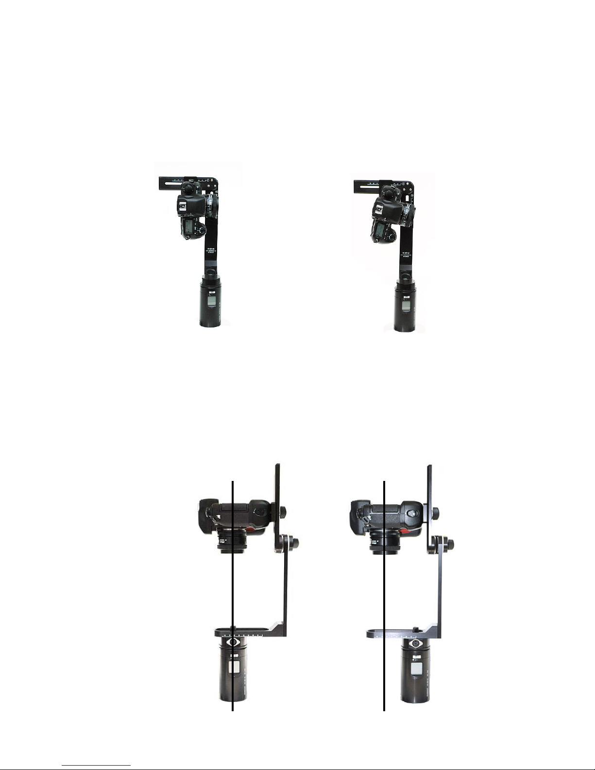
2.1 Setting up the VR Drive Panorama Set (continued)
Step 4: Attach the camera in such a way that the camera is positioned in an exact 90°
angle to the horizon (y-axis). This can be checked with a separate spirit level.
Step 5: Center the camera in the x- and y axis (A+B)
Rotate camera with lens pointing downward using the rotation lever (D).
The camera viewfinder now points on the adjustment bar for x-axis (A). Center the
camera by shifting its position on the x-axis and y-axis (A+B). Rotate the camera back
in its original position (D).
Correct: Wrong:
Shifting along
the x-axis

Instruction Manual Roundshot VR Drive - version 4.0 – January 2010 - © by Seitz Phototechnik AG / Switzerland www.roundshot.ch page 7
2.1 Setting up the VR Drive Panorama Set (continued)
Step 6: Set the nodal point by changing the position of the camera on the
adjustment bar (C).
The basic principle in panoramic photography is to take each shot from the same
turning point. This central axis is called nodal point.
If the nodal point is not accurately set, the perspectives of the images do not match.
This mean that points that lie behind each other do not align when viewed from two
different turning points:
Good nodal point: Bad nodal point:
Shifting along the adjustment bar for nodal point (C):
Instruction Manual Roundshot VR Drive - version 4.0 – January 2010 - © by Seitz Phototechnik AG / Switzerland www.roundshot.ch page 8
2.1 Setting up the VR Drive Panorama Set (continued)
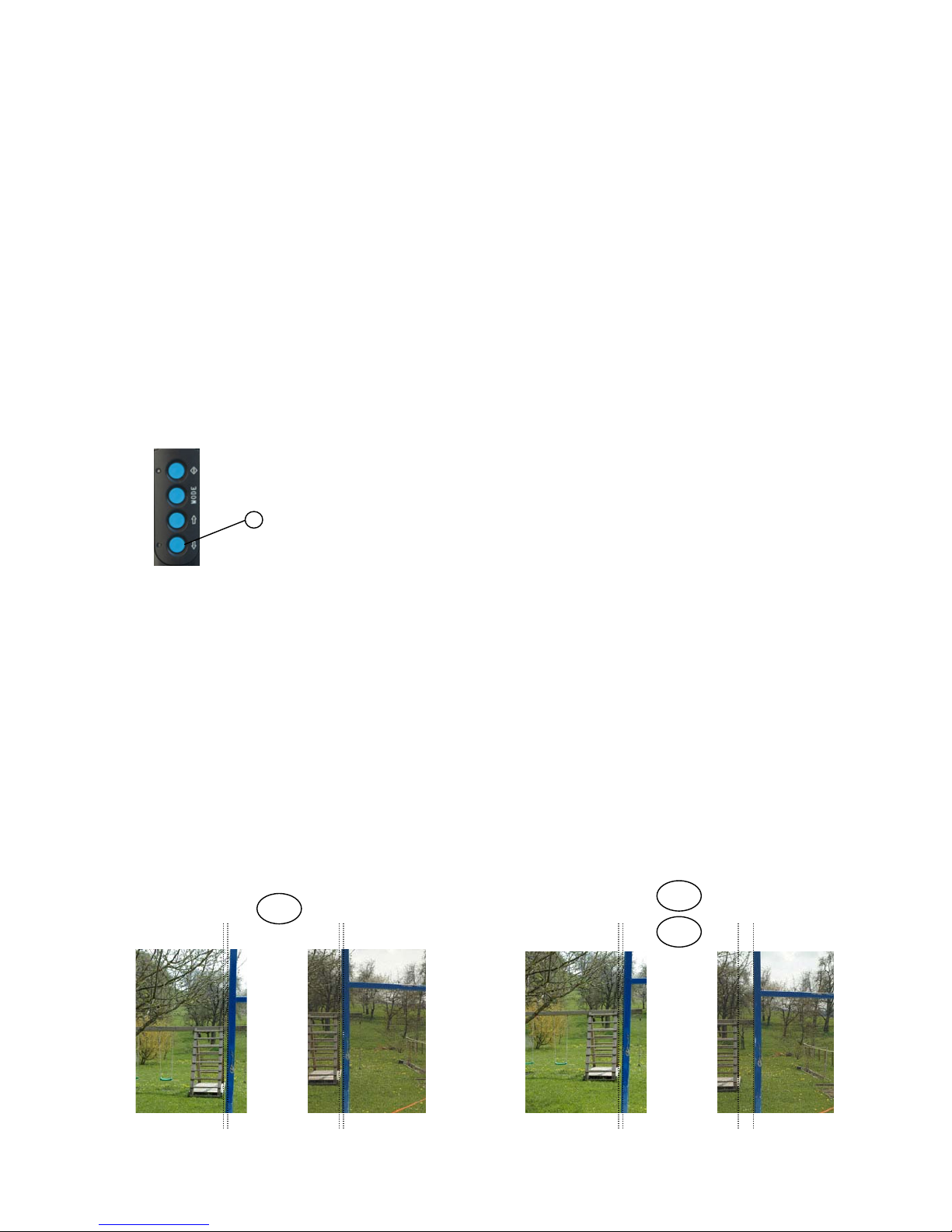
Step 7: Setting the nodal point (continued)
Select two points that lie behind each other in space. Ideal are vertical lines (for instance
of houses, poles, pillars etc.).
Look through the viewfinder of your digital camera.
Position the camera, mounted on the VR Drive, in such a way that both lines are exactly
aligned. Thelineshouldbeeitheron thevery left or very right of the viewfinder /
screen.
Then turn the camera and observe the behaviour of vertical lines in the viewfinder.
If the two lines are still exactly behind each other after turning the camera the nodal point
is correctly set.
If not, change the position of the camera on the adjustment bar (C) forward or backward
and repeat this until both lines are perfectly aligned.
Good nodal point:
Distance between vertical lines does not
change
Bad nodal point:
Distance between vertical lines changes
Power „off“
button
8
Power off the VR Drive motor to make sure that it
is not damaged when turning the VR Head.
This is done by pressing the power „off“ button (8)
for a few seconds.
=
<
>
Instruction Manual Roundshot VR Drive - version 4.0 – January 2010 - © by Seitz Phototechnik AG / Switzerland www.roundshot.ch page 9
2.1 Setting up the VR Drive Panorama Set (continued)
Step 8: Setting the digital camera
Connect the release cable into the camera and plug it into the socket for the release
cable (1) on the VR Drive. Make sure that the plug points to the back of the camera
and not to the front, as otherwise it may be visiblein theimage forsphericalimages.
As light and distance values in a 360° rotation vary greatly, the automatic light meter
and autofocus of the digital camera must be turned off.
Set the exposure to manual and select an average light reading.
Focus manually on the lens, selecting an intermediate focusing distance.
The VR Drive and the digital camera are now ready for image taking.
Setting up the VR Drive Panorama Set is important to obtain the best
possible precision and ease in digital stitching. Note the C-axis values
(nodal points) for different focal lengths in the following table:
Camera + focal length:
…………………………………….
focal length, c-axis value
(nodal point)
mm mm
……………. ……………..
……………. ……………..
……………. ……………..
……………. ……………..
Camera + focal length:
…………………………………….
focal length, c-axis value
(nodal point)
mm mm
……………. ……………..
……………. ……………..
……………. ……………..
……………. ……………..
 Loading...