

Seitz 2A52, 2F55 Operating Instructions Manual

Sicherheit
Bestimmungsgemässe Verwendung
Die Magnetspulen Typen 2A52 bis 2F52 dienen
zum Betätigen von Ventilen der Eugen Seitz AG.
Die passende Magnetspule muss mit dem Hersteller oder einem seiner Repräsentanten ausgewählt werden. Mit der EG-Baumusterprüfbescheinigung PTB 00 ATEX 2211 X sind die
Magnetspulen als Geräte der Kategorie 2 und
der Gerätegruppe II zugelassen und damit für
den Einsatz in Bereichen mit explosionsfähigen
Gas-, Dampf-, Nebel-, Luft-Gemischen der Zonen 1 und 2 sowie Staub-Luft-Gemischen der
Zonen 21 und 22 geeignet.
Autorisierte Personen
Die hier beschriebenen Arbeiten dürfen nur
durch autorisierte Personen ausgeführt werden. Autorisiert sind Personen, die „elektrotechnisch unterwiesen“ sind (EN 60204-1).
Zu dieser Betriebsanleitung
Diese Betriebsanleitung ist Bestandteil des
Produktes und muss in die entsprechende Betriebsanleitung der Anlagen- oder Maschinenbeschreibung integriert werden.
Allgemeine Gefahrenhinweise
Vor Beginn der Anschlussarbeiten
ist sicherzustellen, dass die Betriebsspannung abgeschaltet und
vor unbefugtem Wiedereinschalten
gesichert ist.
Das Gehäuse der Magnetspule kann
über 80 °C heiss sein. Bei Berühren
des Gehäuses besteht Verbrennungsgefahr.
Zur Aufrechterhaltung des Explosionsschutzes müssen unbedingt
die Montagehinweise berücksichtigt werden. Der Einsatzbereich ist
abhängig von der Umgebungstemperatur. Die auf dem Typenschild
angegebene Zuordnung der Temperaturklasse und der maximalen
Oberflächentemperatur zur Umgebungstemperatur muss beachtet
werden. Jegliche Veränderungen an
der Magnetspule sind verboten.
Gewährleistung
Störungsfreier Betrieb
Ein störungsfreier Betrieb der Magnetspule ist
nur dann gewährleistet, wenn die im Kapitel
„Technische Daten“ enthaltenen Eckdaten
eingehalten und die im Kapitel „Betriebsbedingungen“ aufgeführten Bedingungen erfüllt
sind.
Betriebsanleitung
Magnetspulen
2A52 bis 2F55
0102
II 2 G/D
Explosionsschutz-Kennzeichnung
Für Gas-, Dampf-, Nebel-, Luft-Gemische
II 2 G Ex emb II T6, T5 oder T4 (Temperatur-
klasse abhängig von Umgebungstemperatur)
Für Staub-, Luft-Gemische
II 2 D Ex tD A21 IP65 T80°C, T95°C oder
T130°C (max. Oberflächentemperatur ist abhängig von Umgebungstemperatur)
Technische Daten
Nennspannung
gemäss Typenschild: -15 %, +10 %
Nennfrequenz
gemäss Typenschild ±2 %
Nennleistung
gemäss Typenschild
Einschaltdauer
100 % (Dauerbetrieb)
Umgebungstemperatur
bei Nennleistungen ≤ 3 W bzw. ≤ 4 VA
für T1 bis T6 und T80°C: - 20°C bis +60°C
bei Nennleistungen ≤ 4.5 W bzw. ≤ 6 VA
für T1 bis T6 und T80°C: - 20°C bis +50°C
bei Nennleistungen ≤ 6 W bzw. ≤ 8 VA
für T1 bis T6 und T80°C: - 20°C bis +40°C
für T1 bis T5 und T95°C: - 20°C bis +60°C
bei Nennleistungen ≤ 7.5 W bzw. ≤ 10 VA
für T1 bis T5 und T95°C: - 20°C bis +50°C
bei Nennleistungen ≤ 9.5 W bzw. ≤ 13 VA
für T1 bis T5 und T95°C: -20°C bis +40°C
bei Nennleistungen ≤ 14 W bzw. ≤ 18 VA
für T1 bis T4 und T130°C: -20°C bis +40°C
relative Luftfeuchtigkeit
max. 95 % (nicht betauend)
Schutz gegen Verschmutzung
IP 65 gemäss EN 60529
für Spannungsunterbrechung/-einbruch zu-
lässige Werte sind abhängig vom Ventil, ggf.
beim Hersteller erfragen.
Sicherung mit max. dreifachem Nennstrom
der Magnetspule vorschalten (s. Typenschild).
Schaltleistung min. so gross, wie am Einbauort zu erwartender Kurzschlussstrom.
Elektromagnetische Verträglichkeit
Diese Magnetspulen senden keine strahlen-
den Störungen aus (gem. EN 61000-6-3).
Bei Schaltungsart “A” muss mit leitungsge-
führten Störungen gerechnet werden. Mög-
liche Ausschaltüberspannungen:
200 V bei Nennspannung
600 V bei Nennspannung > 60 – 250 V
Magnetspulen sind gegen gestrahlte Stö-
rungen unempfindlich (gem. EN 61000-6-2).
Bei leitungsgeführten Störungen Angaben
zur Stromversorgung beachten.
Zwischen stromführenden und mit Schutz-
leiter verbundenen Teilen sind Steh-Stoss-
spannungen der Überspannungskategorie
III gemäss IEC 60664-1 zulässig.
Erhöhte Anforderungen
Betriebs-/Umgebungsbedingungen mit ionisierender und nichtionisierender Strahlung,
Vibration, Schock, Dauerschock und aggressiven Umgebungsmedien bitte mit Hersteller
absprechen.
≤ 60 V
Montage / Demontage
Vor Beginn müssen „Sicherheit“ und „Allgemeine Gefahrenhinweise“ gelesen und verstan-
den worden sein.
Montage
Magnetspule über Führungsrohr des Ventils
schieben
mit Sicherungsscheibe und Mutter befesti-
gen
Mutter festziehen bis Verdrehen der Ma-
gnetspule durch zu erwartende Erschütte-
rungen nicht mehr möglich ist
Anschlussarbeiten
Deckel öffnen und Magnetspulen über Kabel
(Kupferquerschnitt 0,75 bis 2,5 mm2, Aus-
sen-ø 6 bis 12 mm) an Versorgungsspannung
anschliessen (bei Schaltungsart „E“ Polarität
beachten, Pluspol mit „+“ gekennzeichnet).
Verbindung mit örtlichem Potentialausgleich
über innere Schutzleiterklemme oder äussere
Anschlussklemme
Vor Inbetriebnahme Deckel schliessen und
prüfen, ob angeschlossener Stromkreis mit
Sicherung gem. Typenschild geschützt ist.
Demontage
Anschlusskabel demontieren (“allgemeine
Gefahrenhinweise” beachten)
Befestigungsmutter lösen
Magnetspule von Führungsrohr ziehen
Typenbezeichnung
Die Typenbezeichnung ist wie folgt aufgebaut:
Beispiel einer Typenbezeichnung
2 A 52
Bauform
Schaltungsart
Magnetteil
Eugen Seitz AG CH-8623 Wetzikon Switzerland Phone +41 044 931 80 80 www.seitz.ch info@seitz.ch
Betriebsbedingungen
Stromversorgung
Oberschwingungen haben keinen Einfluss
auf die Funktion, wenn der Effektivwert der
Summe aller Spannungen innerhalb der für
die Nennspannung angegebenen Toleranzen
liegt.
zulässige Spannungsimpulse:
Spitzenwert:
Zeitdauer:
≤ 1’000V
≤ 1,5ms
Entsorgung
Zur Sicherstellung des Explosionsschutzes
dürfen Magnetspulen nicht repariert werden. Entsorgung als Sondermüll oder an
Hersteller zurücksenden.
© EUGEN SEITZ AG 2008 Art. Nr. 128.207.01 Rev. 5 Printed in Switzerland 0803/10.0 Technische änderungen und änderungen im Lieferumfang vorbehalten.
Safety
Correct use
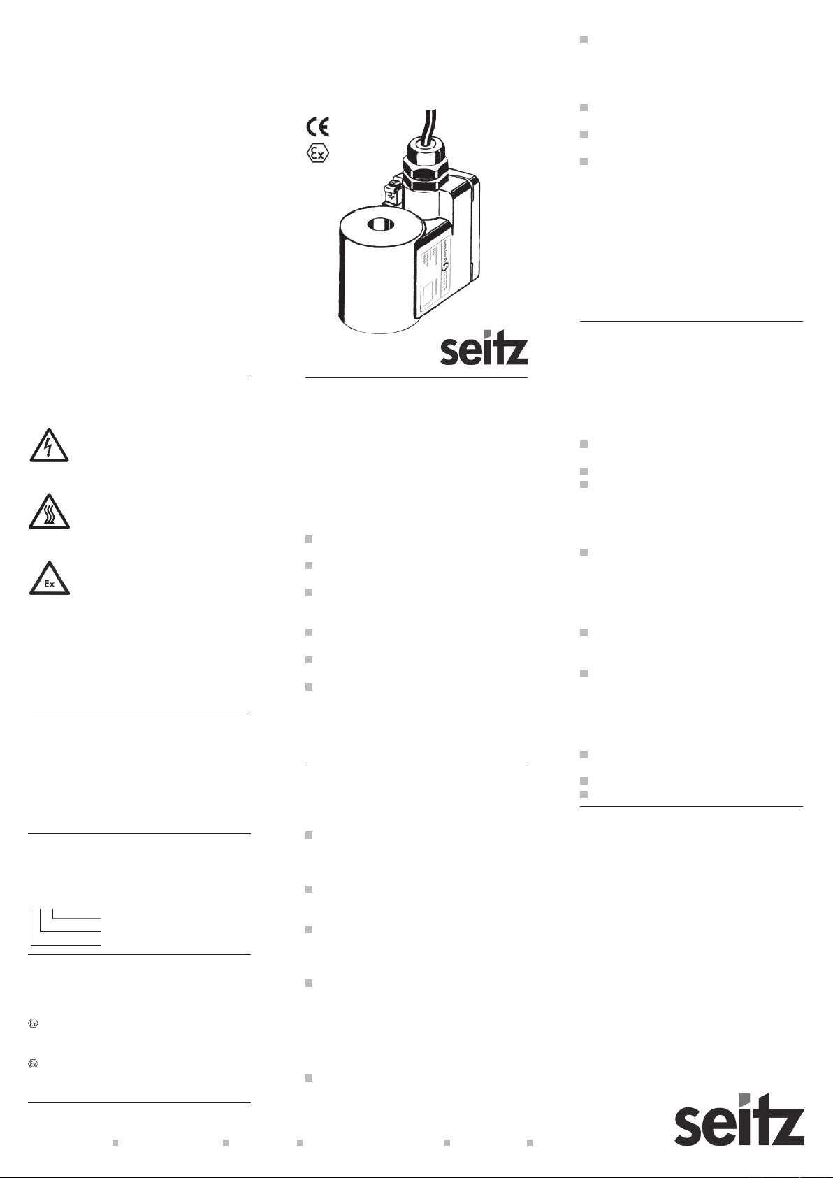
Solenoid types 2A52 to 2F55 are used for operating Eugen Seitz AG valves. The appropriate
solenoid must be selected in conjunction with the
manufacturer or one of his representatives. The
solenoids are classified as category 2 and equipment-group II devices in compliance with ECtype-examination certificate PTB 00 ATEX 2211
X and are therefore suitable for use in areas with
potentially explosive gas-, vapour-, mist- and air
mixtures (zones 1 and 2) and in areas with dust
and air mixtures (zones 21 and 22).
Authorised persons
The tasks described here may only be carried
out by authorised personnel. Authorised personnel are those persons that have undergone
training in electrical engineering (EN 60204-1).
Concerning these operating instructions
These operating instructions form a component
part of the product and must be integrated in the
relevant operating instructions of the system- or
machine description.
General Safety Warnings
Before connection work begins, it
must be ensured, that the power supply is disconnected and protected
against unauthorised reconnection.
The housing of the solenoid can
reach a temperature of more than
80ºC. The danger of burning exists
when the housing is touched.
In order to maintain protection against
explosion, the assembly instructions
must be absolutely adhered to. The location where this device is allowed to
use in dependent upon the prevailing
ambient temperature. Pay attention
to the allocation of temperature class
and maximum surface temperature
to ambient temperature stated on the
name plate. Modifications of any kind
in the solenoids are prohibited.
Warranty
Trouble-free operation
Trouble-free operation is only assured if the prime information contained in chapter „Technical
Data“ is adhered to and the conditions listed in
„Operating Conditions“ are fulfilled.
Type Designation
The type designation is composed as follows:
2 A 52
Construction type
Circuit type
Solenoid size
Explosion Protection
For gas-, vapour-, mist- and air mixtures
II 2 G Ex emb II T6, T5 or T4 (temperature
class dependent on ambient temperature)
For dust- and air mixtures
II 2 D Ex tD A21 IP65 T80°C, T95°C or T130°C
(max. surface temperature is dependent on ambient temperature)
Operating instructions
solenoids
2A52 to 2F55
0102
II 2 G/D
Technical Data
Rated voltage
According to name plate -15 %, +10 %
Rated frequency
According to name plate ±2 %
Rated power
According to name plate
Operating time
100 % (continuous duty)
Ambient temperature
with rated power ≤ 3 W or ≤ 4 VA
for T1 to T6 and T80°C: -20º C to +60º C
with rated power ≤ 4.5 W or ≤ 6 VA
for T1 to T6 and T80°C: -20º C to +50º C
with rated power ≤ 6 W or ≤ 8 VA
for T1 to T6 and T80°C: -20º C to +40º C
for T1 to T5 and T95°C: -20º C to +60º C
with rated power ≤ 7.5 W or ≤ 10VA
for T1 to T5 and T95°C: -20º C to +50º C
with rated power ≤ 9.5 W or ≤13VA
for T1 to T5 and T95°C: -20º C to +40º C
with rated power ≤ 14 W or ≤ 18 VA
for T1 to T4 and T130°C: -20º C to +40º C
Relative humidity
Max. 95 % (non-condensing)
Protection against soiling
IP 65 according to EN 60529
Operating Conditions
Power supply
Harmonic oscillations have no effect on the
functioning of the device if the r.m.s. value of
the sum of all the voltages lies within the tolerances specified for the rated voltage.
Permissible voltage impulses:
Peak value:
Duration:
The permissible values for voltage interrup-
tions or loss depend on the valve. If necessary, these can be obtained from the manufacturer.
The device must be protected for up to a ma-
ximum of three times the rated current of the
solenoid (see name plate). Breaking capacity
at least as great as the short-circuit current to
be expected at the place of installation.
Electromagnetic compatibility
These solenoids do not emit any radiated dis-
turbances (according to EN 61000-6-3).
≤ 1000 V
≤ 1.5 ms
Conducted disturbances are to be expected
in the case of circuit type „A“. Possible tran-
sient switching voltages:
200 V at rated voltage
600 V at rated voltage > 60 V – 250 V
Solenoids are not sensitive to radiated distur-
bances ( according to EN 61000-6-2).
For conducted disturbances, please consult
the specification for the power supply.
Surge voltages of the over-voltage category
III according to IEC 60664-1 are permissible
between current-carrying parts and those
parts connected with the protective con-
ductor.
Extreme demands
Please consult the manufacturer to discuss
extreme operating-/environmental conditions
such as ionising- and non-ionising radiation,
vibration, shock, permanent shock and hostile
environmental conditions.
≤ 60 V
Assembly/ Disassembly
Before beginning, the „Safety“ and „General
Safety Warnings“ sections must be read and
fully understood.
Assembly
Slide solenoid over the guide tube of the val-
ve.
Fasten with securing washer and nut.
Tighten the nut until loosening of the solenoid
due to expected shocks and vibrations is no
longer possible.
Connection work
Open the cover and connect the solenoid
to the power supply using a cable (copper
crosssection of 0.75 to 2.5 mm2, outer ø 6 to
12 mm). In the case of circuit type „E“, please
observe polarity. Positive pole is marked with
a „+“ sign.
Connection with local potential equalisation
via internal earthing clamp or external con-
nection clamp.
Before beginning initial operation, close the
cover and check whether the connected cur-
rent circuit is protected with a fuse according
to that stated on the name plate.
Disassembly
Disconnect the connection cable (observe
„General Safety Warnings“).
Loosen fastening nut.
Withdraw solenoid from the guide tube.
Disposal
To ensure explosion protection, solenoids
may not be repaired. Dispose of as special
waste or return to the manufacturer.
Eugen Seitz AG CH-8623 Wetzikon Switzerland Phone +41 044 931 80 80 www.seitz.ch info@seitz.ch
© EUGEN SEITZ AG 2008 Art. Nr. 128.207.01 Rev. 5 Printed in Switzerland 0803/10.0 Subject of technical changes and changes in the scope of delivery.
 Loading...