

Page 1

USER’S GUIDE
Thermal Printer
MPU-L465
Read this manual carefully before use.
Keep this manual in a place where it can
be accessed quickly.
Seiko Instruments Inc.
Page 2

MPU-L465 THERMAL PRINTER USER’S GUIDE
Document Number: UXXXXXXXXXXX
First Edition:
The information contained herein is the property of SII and shall not be reproduced in whole or in part
without prior written approval of SII.
SII reserves the right to make changes in the specifications and materials contained herein without
notice and shall not be responsible for any damages (including consequential) caused by reliance on
the materials presented, including but not limited to typographical, arithmetic, and listing errors.
This product complies with EU RoHS Directive(2002/95/EC).
For use in Turkey
Complies with Electrical and Electronic Equipment Directive.
Türkiye’ deki Kullanıcılar için
EEE Yönetmeliğine Uygundur.
Copyright 2009 by Seiko Instruments Inc.
All rights reserved.
is a trademark of Seiko Instruments Inc.
Bluetooth is registered trademarks of Bluetooth SIG, Inc.
Applicable EC Directive and Standards
Product: Thermal Printer MPU-L465-1xC-E
Directive:
Standards
Note that the radio frequency band used this equipment has not been harmonized in all the EU.
Title
1999/5/EC EC Radio and Telecommunications Terminal Equipment Directive
EN 300 328 V1.7.1
EN 301 489-1 V1.6.1
EN 301 489-17 V1.2.1
EN55022
EN55024
EN61000-3-2
EN61000-3-3
EN60950-1
Page 3

This product may be used in following all EU and EFTA countries:
EU
Austria, Belgium, Denmark, Finland, France,
Germany, Greece, Ireland, Italy, Luxembourg,
Portugal, Spain, Sweden, The Netherlands, United Kingdom
EFTA
Iceland, Norway, Switzerland, Liechtenstein
Product: Thermal Printer MPU-L465-0xC-E
Directive:
Standards
Product: AC adapter PW-0904-W2-E
Directive:
Standards
Product: Battery Charger PWC-L07A1-W1-E
Directive:
Standards
Title
2004/108/EC EC Electromagnetic Compatibility Directive
EN55022
EN55024
EN61000-3-2
EN61000-3-3
Title
2004/108/EC EC Electromagnetic Compatibility Directive
2006/95/EC EC Low Voltage Directive
EN 55022
EN 61000-3-2
EN 61000-3-3
EN 55024
EN 60950-1
Title
2004/108/EC EC Electromagnetic Compatibility Directive
2006/95/EC EC Low Voltage Directive
EN 55022
EN 61000-3-2
EN 61000-3-3
EN 55024
EN 60950-1
Page 4

Federal Communications Commission (FCC) compliance statement
This equipment has been tested and found to comply with the limits for a Class B digital device,
pursuant to part 15 of the FCC Rules. These limits are designed to provide reasonable protection
against harmful interference in a residential installation. This equipment generates, uses and can
radiate radio frequency energy and, if not installed and used in accordance with the instructions,
may cause harmful interference to radio communications. However, there is no guarantee that
interference will not occur in a particular installation. If this equipment does cause harmful
interference to radio or television reception, which can be determined by turning the equipment off
and on, the user is encouraged to try to correct the interference by one or more of the following
measures:
- Reorient or relocate the receiving antenna.
- Increase the separation between the equipment and receiver.
- Connect the equipment into an outlet on a circuit different from that to which the
receiver is connected.
- Consult the dealer or an experienced radio/TV technician for help.
Any changes in this certified device could void your legal right to operate it.
RF exposure compliance
1) To comply with FCC/IC RF exposure compliance requirements, a separation distance of at least
20 cm must be maintained between the antenna of this device and all persons.
2) This transmitter must not be co-located or operating in conjunction with any other antenna or
transmitter.
Page 5

Industry Canada (IC) compliance statement
Operation is subject to the following two conditions: (1) this device may not cause interference,
and (2) this device must accept any interference, including interference that may cause
undesired operation of the device.
Page 6

INTRODUCTION
Thank you for purchasing the MPU-L465 thermal printer.
This USER’S GUIDE explains how to handle MPU-L465 thermal printer (hereinafter referred to as
printer), specified AC adapter, specified battery charger, specified battery
pack and specified AC cable (hereinafter, omit “specified”).
Read through the SAFETY PRECAUTIONS and OPERATING PRECAUTIONS carefully before using
the printer.
Keep this user’s guide in a place where it can be accessed quickly.
For more detailed technical information on this printer, refer to the MPU-L465 THERMAL PRINTER
TECHNICAL REFERENCE.
The User’s Guide consists of the following sections.
SAFETY PRECAUTIONS ............................................................................................ 2
OPERATING PRECAUTIONS ................................................................................... 13
1. PREPARATION ......................................................................................................... 16
2. NAMES OF PARTS.................................................................................................... 17
3. POWER CONNECTING ............................................................................................ 22
4. PAPER SETUP .......................................................................................................... 25
5. ATTACHING AND DETACHING THE BELT CLIP AND STRAP................................ 31
6. TEST PRINTING ........................................................................................................ 32
7. FUNCTION SETTINGS.............................................................................................. 33
8. CONNECTING TO THE HOST COMPUTER............................................................. 41
9. CHARGING THE BATTERY PACK............................................................................ 43
10. THERMAL HEAD/PLATEN ROLLER MAINTENANCE.............................................. 46
11. TROUBLESHOOTING ............................................................................................... 47
12. SPECIFICATIONS ..................................................................................................... 48
13. OPTIONAL UNITS AND CONSUMABLES................................................................. 51
For more details, please ask your dealer for a copy of the MPU-L465 Technical Reference.
- 1 -
Page 7

SAFETY PRECAUTIONS
The following symbols are used in this manual in order to make proper use of the printer and avoid
incidental damages.
Follow the guidelines marked with each individual symbol.
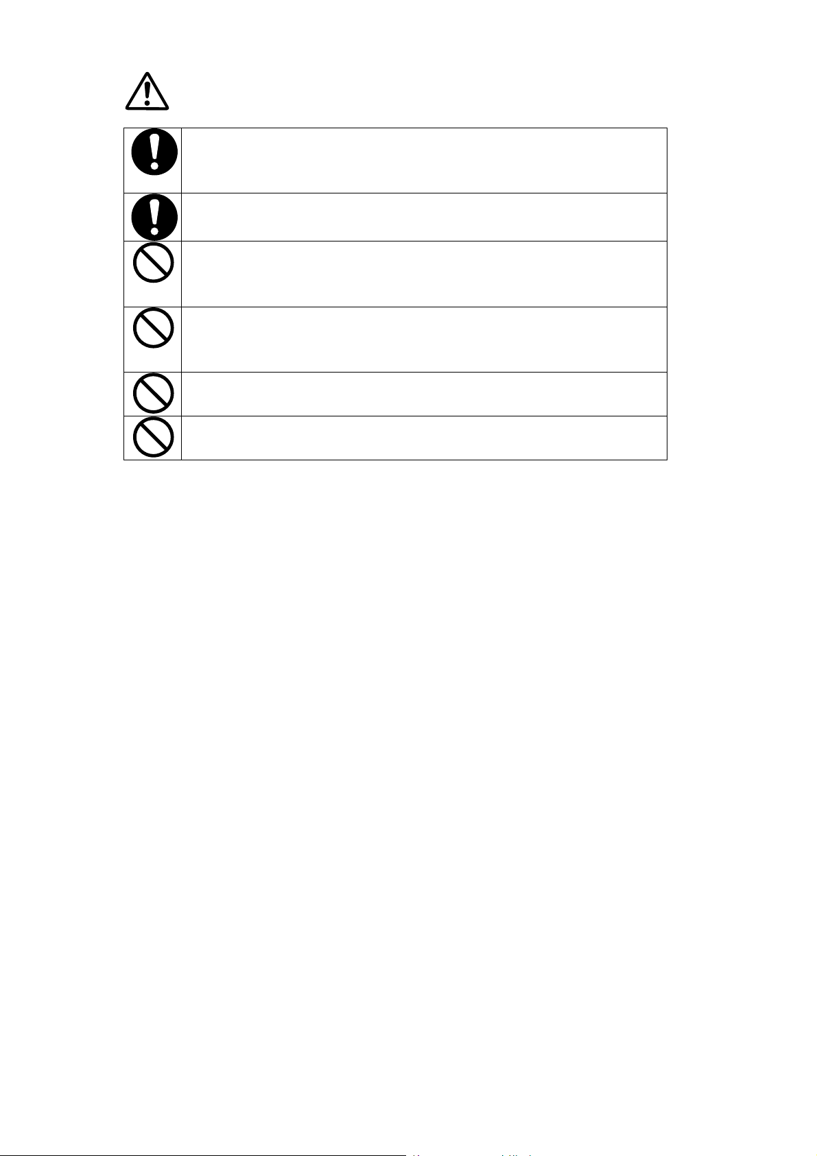
Failure to follow the guidelines marked with this symbol
WARNING
CAUTION
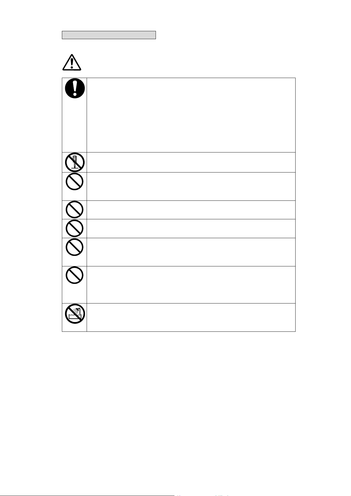
Symbol Examples
The symbol indicates caution (including danger and warning).
This example indicates warning or caution.
The symbol indicates prohibition.
This example indicates prohibition of disassembling.
The symbol
This example asks you to unplug the power cable.
could result in serious personal injury or death.
Failure to follow the guidelines marked with this symbol
could result in minor personal injury or product and/or
peripheral damage.
indicates requirements or what must be done.
- 2 -
Page 8

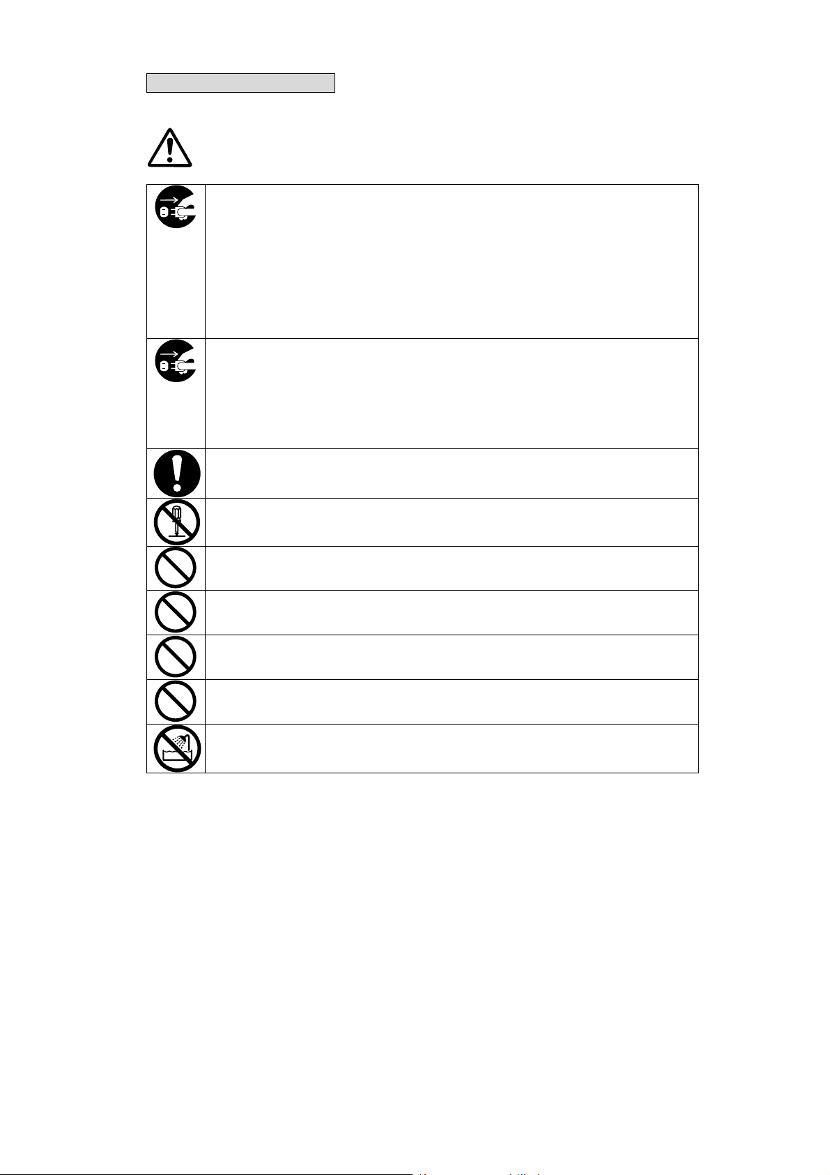
Warning on the Printer
WARNING
If you find any of the following abnormalities in the printer, power off the printer, unplug
the AC cable, and remove the battery pack from the printer.
♦ When an unusual state was not returned to the normal’s.
♦ When the printer gave out a nasty smell or smoke, or generated noise.
♦ When metallic powders, water or other foreign substances entered the printer.
♦ When the printer case was broken.
If not, it might cause fire or an electricshock. Please ask your dealer for repair.
NEVER put metallic powders, water or other foreign substances into the printer from its
opening.
If not, it might cause fire or an electricshock.
NEVER disassemble or remodel the printer. DO NOT try to repair the printer yourself.
If not, it might cause fire, an accident or failure.
DO NOT use any power supply other than our dedicated AC adapter and battery pack.
If not, there is fear of burst, ignition, or generation of heat that might cause fire or an
accident.
Power off the printer, when you attach and detach the battery pack to and from the
printer.
If not, it might cause an electricshock.
The antenna(s) used for this transmitter must be installed to provide a separation
distance of at least 20 cm from all persons and must not be co-located or operating in
conjunction with any other antenna or transmitter.
- 3 -
Page 9

CAUTION
When not in use for long periods of time, power off the printer, unplug the AC cable, and
remove the battery pack from the printer.
If not, it might cause fire or an electricshock.
When you clean the printer, power off the printer, unplug the AC cable, and remove the
battery pack from the printer.
If not, it might cause fire or an electricshock.
Keep the printer away from children.
If not, it might cause injury.
Keep the printer away from direct sun and high temperature. If not, it might cause fire
or a failure.
Keep the printer away from high humidity and dust.
If not, it might cause fire or a failure.
While using the printer, NEVER cover cloth, etc. over it.
If not, it might cause fire or a failure.
Install the printer in a vibration-free place.
Keep the printer away from unstable, shaky, unsteady and slanting environment.
If not, it might cause injury or a failure.
The thermal printhead might reach a high temperature just after printing. NEVER touch
the printhead. Remove paper jam and clean the printhead after making sure that the
printhead has cooled down.
If not, it might cause injury.
The printer is designed so that you can directly touch the thermal head, the paper sensor,
and the platen roller due to improvement of paper insertion mechanism. However,
NEVER touch any of them directly except where necessary.
If not, it might cause injury or a failure.
DO NOT touch the cutter.
If not, it might cause injury.
When inserting the battery pack into the printer, secure the battery cover.
If not, the battery cover is turned over, the battery jumps out, and injury or a failure may
happen.
Do not make your hair, etc. which are easily entangled in the printer approach to the
printer during the operation.
You could be caught into the printer, causing an injury.
- 4 -
Page 10

When the AC adapter is used
WARNING
If you find any of the following abnormalities in the AC adapter, unplug the AC cable.
♦ When the AC adapter gave out a nasty smell or smoke, or generated noise.
♦ When the printer case was broken.
If not, it might cause fire or an electricshock. Please ask your dealer for repair.
NEVER disassemble or remodel the AC adapter. If not, it might cause fire, an accident,
or a failure.
DO NOT use any AC cable other than our dedicated one.
If not, it might cause fire, an accident, or a failure.
DO NOT use the AC adapter at any voltage other than the specified power supply
voltage.
If not, it might cause fire, an accident, or a failure.
DO NOT touch the metallic areas of the AC adapter and the connector to avoid
shortcircuiting.
If not, it might cause fire, an accident, or a failure.
Keep the AC adapter away from rain and water. If not, it might cause fire, an accident or
a failure.
- 5 -
Page 11

CAUTION
Unplug the AC cable when cleaning the AC adapter.
If not, it might cause an electricshock.
Keep the AC adapter away from children.
If not, it might cause injury.
Keep the AC adapter away from direct sun and high temperature. If not, it might cause
fire or a failure.
Keep the AC adapter away from high humidity and dust.
If not, it might cause fire or a failure.
DO NOT touch the AC adapter by wet hand.
If not, it might cause an electricshock.
While using the AC adapter, NEVER cover cloth, etc. over it.
If not, it might cause fire or a failure.
Keep the AC adapter away from unstable, shaky, unsteady and slanting environment.
If not, it might cause injury or a failure.
- 6 -
Page 12
When the battery pack is used
WARNING
If you find any of the following abnormalities in the battery pack, remove the battery
pack from the printer and keep away from fire.
♦ When the battery pack gave out a nasty smell, reached an extraordinarily high
temperature or showed any unusual sign.
♦ When the battery pack case was broken.
♦ When leakage was found.
If not, there is fear of leakage, generation of heat, burst, or ignition that might cause fire
or injury.
NEVER disassemble, remodel, or solder the battery pack. If not, there is fear of
leakage, generation of heat, burst, or ignition that might cause fire or injury.
DO NOT charge the battery pack except by the dedicated battery charger.
If not, there is fear of leakage, generation of heat, burst, or ignition that might cause fire
or injury.
DO NOT touch the metallic area of the battery pack to avoid shortcircuiting.
If not, there is fear of heat generation or an electricshock that might cause fire or injury.
DO NOT throw the battery pack into fire and DO NOT heat it. If not, there is fear of leakage,
generation of heat, burst, or ignition that might cause fire or injury.
DO NOT charge the battery pack in a place at 35 °C / 95 °F or more under burning
scorching or in the close vicinity of fire. If not, there is fear of leakage, generation of
heat, burst, or ignition that might cause fire or injury.
DO NOT apply strong impact to the battery pack with a hammer or a nail, and DO NOT
crush it.
If not, there is fear of leakage, generation of heat, burst, or ignition that might cause fire
or injury.
DO NOT put the battery pack into water. Always keep it away from rain and water. If
not, there is fear of leakage, generation of heat, burst, or ignition that might cause fire or
injury.
- 7 -
Page 13
CAUTION
If liquid inside the battery pack enter your eyes, immediately wash it away with clean water
and take a physician's medical treatment.
If not, your eyesight might be damaged.
Keep the battery pack away from children.
If not, it might cause injury.
Keep the battery pack away from direct sun and high temperature, especially in a car. If
not, there is fear of leakage, generation of heat, burst or ignition that might cause fire or
injury.
DO NOT use or keep the battery pack in a place where is humid and dusty.
If not, there is fear of leakage, generation of heat, burst or ignition that might cause fire
or injury.
DO NOT touch the battery pack by wet hand. If not, it might cause an electricshock or a
failure.
Keep the battery pack away from unstable, shaky, unsteady and slanting environment.
If not, it might cause injury or a failure.
- 8 -
Page 14
When the charger is used
WARNING
When you find any of the following abnormalities in the charger, unplug the AC cable
from the wall socket.
♦ When the charger gave out a nasty smell, reached an extraordinarily high
temperature or showed any unusual sign.
♦ When metallic powders, water or other foreign substances entered the charger.
♦ When the charger case was broken.
If not, it might cause fire or an electricshock. Please ask your dealer for repair.
When the charger gave out a smoke or nasty smell, reached an extraordinarily high
temperature or showed any unusual sign during its charging. Unplug the AC cable
from the wall socket.
If not, there is fear of leakage, generation of heat, burst or ignition that might cause fire
or injury.
NEVER put water and foreign substances into the charger.
If not, it might cause fire or an electricshock.
NEVER disassemble or remodel the charger. If not, it might cause fire or an
electricshock.
DO NOT connect any battery pack other than our specified one to the charger.
If not, there is fear of burst, ignition or generation of heat that might cause fire or injury.
DO NOT use any AC cable other than our dedicated one in the charger.
If not, there is fear of heat generation, or ignition that might cause fire or an accident.
DO NOT use the charger at any power supply voltage other than the specified one.
If not, it might cause fire, an electricshock or a failure.
DO NOT touch any and all of the output terminals of the charger to avoid shortcircuiting.
If not, it might cause fire, an electricshock or a failure.
DO NOT wet the charger. Always it away from moisture. If not, it might cause fire, an
electricshock or a failure.
- 9 -
Page 15

CAUTION
Unplug the AC cable except when using the charger.
The charger is operating whether or not it is equipped with the battery pack.
Unplug the AC cable when cleaning the charger.
If not, it might cause an electricshock.
Keep the charger away from children.
If not, it might cause injury.
Keep the charger away from direct sun light and high temperature. If not, it might cause
fire or a failure.
DO NOT put the charger in a place where is humid and dusty.
If not, it might cause fire or a failure.
DO NOT touch the charger by wet hand.
If not, it might cause an electricshock.
While using the charger, DO NOT cover cloth, etc. over it.
If not, it might cause fire or a failure.
Keep the charger away from unstable, shaky, unsteady and slanting environment.
If not, it might cause injury or a failure.
- 10 -
Page 16

When the AC cable is used
WARNING
Unplug the AC cable if the AC adapter or the charger is damaged.
If not, it might cause fire, an electricshock, or a failure.
Keep the AC adapter and the AC cable of the charger away from dust and metallic
powders.
If not, it might cause fire or an electricshock.
Plug the AC adapter and the AC cable of the charger completely.
If not, it might cause fire or an electricshock.
NEVER damage the AC adapter and the AC cable of the charger. DO NOT bent the AC
cable forcibly, DO NOT place any heavy goods on it, DO NOT pull it, and DO NOT twist
it.
If not, it might cause fire, an electricshock, or a failure.
Always use the dedicated AC cable in the AC adapter and the charger. Use the
respective AC cable specified by country and block shown below.
In Japan: Model CB-JP04-18A-E
In North America: Model CB-US01-18*-E, CB-US04-18A-E
In EU: Model CB-CE01-18B-E
- 11 -
Page 17

CAUTION
When you unplug the AC cable of the AC adapter or the charger from the respective
wall socket or the plug, remove it while holding the connecting area.
Exposure or disconnection of the cable might cause fire or an electricshock.
- 12 -
Page 18

OPERATING PRECAUTIONS
Please follow the precautions shown below to ensure full functionality of the printer and thermal
paper.
■ Printer
♦ Switch the power off when not in use.
♦ DO NOT give a shock intentionary by dropping or hitting the printer. The printer with a rubber
cover has an excellent structure against impact on each surface. However, it may be broken
depending on the surface conditions, the angle of fall or the degradation state of the printer, and
so forth.
♦ Give attention to ambient temperature and humidity during use of the printer. Proper operating
environment is as follows:
Ambient temperature: -15 °C to 50 °C / 5 °F to 122 °F
Relative humidity: 10% to 85% (no-condensing)
♦ DO NOT set/put the printer near any device that generates strong electromagnetic fields, like a
motor in a copying machine.
♦ DO NOT open the paper cover during printing.
♦ DO NOT remove or reinstall the interface cable during printing or transmission. DO NOT touch the
connectors of the interface cable during printing.
♦ NEVER close the paper outlet port or press down the paper which came out. If not, it might cause
paper jam.
♦ Cut only a part of liner with the paper cutter attched to the paper outlet. It may cause a cutting error
or make the cutting edge dull due to label adhesive sticking to the cutter if cutting a part of label
sheet.
♦ Remove the battery pack, when you do not use the printer for long periods of time. If not, it might cause
excessive discharge and then will not allow you to use the printer even after it is charged.
♦ Clean the printer exterior with a soft, lint-free cloth where necessary. DO NOT use alcohol and
other solvent.
♦ Before use, always clean the terminals using a dry, soft, lint-free cloth. If the terminals are dirty, it
may not allow you to ensure proper contact.
♦ Be sure to wipe the printhead with a soft swab, etc. when cleaning the thermal printhead.
♦ Unplug the AC cable except when using the AC adapter.
- 13 -
Page 19

♦ When storing the battery pack for long periods of time, keep it in a cool place. If possible, avoid
long-term storage in the fully charged state. It may affect the battery life.
♦ Clean the terminals of the battery pack regularly (wipe them with a dry cloth).
♦ In order to fully demonstrate the performance of the battery pack, charge the battery at room
temperature and the temperature of the battery pack ranging from 0 °C to 35 °C / 32 °F to 95 °F.
♦ Clean the terminals of the dedicated charger regularly (wipe them with a dry cloth).
♦ DO NOT connect the AC cable of the AC adapter or the charger to the power supply wall socket
which was already connected to any other devices which generate noise.
♦ High-print-rate printing might cause irregular printouts or generate loud noise. This is not a failure
in the printer, but an inherent paper phenomenon.
♦ Always use roll paper whose width is at least 4 mm wider than the print width.
♦ To ensure the bar code printing quality, parts having high printed ratios may be light at a low
temperature.
♦ When using a Bluetooth interface, the radio environment around the printer may cause a failure in
communications. This is due to the specifications of Bluetooth, which is a radio communications
standard.
♦ When handling this product, be aware of static electricity. If the static electricity is discharged, this
could case communication failure. When this problem occurs, disconnect the USB connector that
is connected to the host device and wait few seconds before connect it again.
♦ If dew condensation occurs on the roll label, the peel function may not work well or paper jam may
occur. Avoid drastic changes in the environment.
- 14 -
Page 20

■ Thermal Paper
♦ Store the paper in a cool, dry, and dark place.
♦ DO NOT rub the paper with hard objects.
♦ DO NOT leave the paper near organic solvents.
♦ DO NOT allow the paper to touch plastic film, eraser, or adhesive tape for long periods of time.
♦ DO NOT stack the paper together with diazo and wet-type copies immediately after copying.
♦ DO NOT use chemical glue when starching up.
♦ Always use the specified thermal paper. See Section 13, Optional Units and Consumables, for
details.
Tips and Hints
In addition to safety and operating precautions marked with the respective symbols, tips and hints are
also provided herein (more specifically, from the subsequent pages) to facilitate customers’ smooth
operation of the printer:
•
This box contains helpful tips and hints to be remembered.
Hints
Items To be Remembered
- 15 -
Page 21

AC cable
s*1 AC adapter
Battery pack
Battery charger
Be
lt clip
*2 Shoulder belt*2
Interface cable
Interface cable
1. PREPARATION
Once you have opened the carton, make sure it contains the printer and its User’s Guide. Please
notice that printer functions and package contents differ depending on the printer model.
Main unit (Standard printer)
(-02∗/-16∗)
Main unit (Peeler mounted
printer) (-17∗)
User’s Guide (this manual)
The following are available as optional units:
*1 AC cables for an optional AC adapter and a battery charger are not contained in this carton. Purchase
each. An AC cable can be used for both the AC adapter and the battery charger.
*2 The belt clip allows you to attach the printer to your belt; and the shoulder belt allows you to carry it on
your shoulder.
Keep the carton and packing materials safe for future transport or long-term storage.
(USB)
(Serial)
- 16 -
Page 22

2. NAMES OF PARTS
(12)
(9)
(15)
(11)
(7)
Standard printer (-02∗/-16∗)
(1) POWER button
(14)
(12)
(16)
(13)
(10)
(6)
(7)
(8)
(3) REPRINT button
(5)
(2)
(3)
(4)
(1)
This button is used to turn the printer ON and
OFF. To power the printer on, hold down the
POWER button until the POWER lamp lights. To
turn the printer off, hold down the POWER button
until the POWER lamp goes off.
(2) FEED button
This button is used to feed the paper. Once this
button is pressed when using the marked paper,
the paper is fed to the start of the next paper.
Once this button is pressed when not using the
marked paper, the paper is slightly and gradually
fed. Continuing pressing this button advances
paper feeding.
- 17 -
This button is used to print the previous print
again. Reprint is available when the REPRINT
lamp lights. When the button print is valid, the
REPRINT button has the function to start the next
print. When the REPRINT lamp is blinking 3
times (fast blinking), the REPRINT button
cancels the “suspension” and can start the next
print.
(4) POWER lamp
The POWER lamp lights when the printer is
turned on. See the Power Lamp Indication
shown on page 21 for details.
Page 23

(5) REPRINT lamp
(11) Paper guide unit
The REPRINT lamp lights in case the previous
print can be reprinted.
(6) Interface cover
This cover is used to connect the interface cable
and the AC adapter, and insert the connector.
Open the rubber cover and insert the connector.
(7) Battery rubber cover
This cover is used to mount and secure the
battery pack. Open the rubber cover and then
attach and detach the battery pack.
(8) Battery release lever
This lever is used to remove the battery pack
from the printer.
(9) Paper cover open lever
This lever is used to open the paper cover in
order to install the paper.
(10) Paper outlet port
This is a paper outlet port equipped with a paper
cutter.
This unit is used to install paper. Paper with
various width can be installed.
(12) Paper guide
This guide releases the paper guide lock via lever
(13) according to the paper width and changes
the paper guide width. By attaching and
detaching adapters to it, it is possible to fit several
types of inner diameter.
(13) Paper guide lock lever
This lever is used to release the parper guide lock
when chaging the position of the left and right
paper guides.
(14) Thermal printhead
This printhead prints characters on the paper. Be
careful that It reaches a high temperature just
after printing.
(15) Paper sensor
This sensor detects “no paper “and “timing-mark.”
(16) Paper cutter
This unit cuts paper.
- 18 -
Page 24

(11)
(12)
(9)
(17)
(18)
(19)
(5)
(2)
(12)
(13)
(7)
(10)
(6)
(3)
(4)
(1)
(15)
(14)
(7)
(16)
Peeler mounted printer (-17∗)
(1) POWER button
This button is used to turn the printer ON and OFF.
To power the printer on, hold down the POWER
button until the POWER lamp lights. To turn the
printer off, hold down the POWER button until the
POWER lamp goes off.
(2) FEED button
This button is used to feed the paper. Once this
button is pressed when using the marked paper,
the paper is fed to the start of the next paper.
Once this button is pressed when not using the
marked paper, the paper is slightly and gradually
fed. Continuing pressing this button advances
paper feeding.
(3) REPRINT button
This button is used to print the previous print
again. Reprint is available when the REPRINT
(8)
lamp lights. When the button print is valid, the
REPRINT button has the function to start the next
print. When the REPRINT lamp is blinking 3 times
(fast blinking), the REPRINT button cancels the
“suspension” and can start the next print.
(4) POWER lamp
The POWER lamp lights when the printer is
turned on. See the Power Lamp Indication shown
on page 21 for details.
(5) REPRINT lamp
The REPRINT lamp lights in case the previous
print can be reprinted.
(6) Interface cover
This cover is used to connect the interface cable
and the AC adapter, and insert the connector.
Open the rubber cover and insert the connector.
- 19 -
Page 25

(7) Battery rubber cover
(13) Paper guide lock lever
This cover is used to mount and secure the
battery pack. Open the rubber cover and then
attach and detach the battery pack.
(8) Battery release lever
This lever is used to remove the battery pack from
the printer.
(9) Paper cover open lever
This lever is used to open the paper cover in order
to install the paper.
(10) Paper outlet port
This is a paper outlet port equipped with a paper
cutter.
(11) Paper guide unit
This unit is used to install paper. Paper with
various width can be installed.
(12) Paper guide
This lever is used to release the parper guide lock
when chaging the position of the left and right
paper guides.
(14) Thermal printhead
This printhead prints characters on the paper. Be
careful that It reaches a high temperature just
after printing.
(15) Paper sensor
This sensor detects “no paper “and “timing-mark.”
(16) Paper cutter
This unit cuts paper.
(17) Roller Cover Open Lever
This lever is used to open the roller cover when
setting the stripping paper in use of the label
peeling function.
(18) Stripping Paper Outlet port
This guide releases the paper guide lock via lever
(13) according to the paper width and changes the
paper guide width. By attaching and detaching
adapters to it, it is possible to fit several types of
inner diameter.
- 20 -
The stripping paper is outlet when the label
peeling function is used.
(19) Stripping Paper Cutting Sub Blade
This blade is used as an auxiliary blade when
cutting excess stripping paper in use of the label
peeling function.
Page 26

[POWER Lamp Indication]
The POWER lamp comes in three colors - - -green, red, and orange.
Indication POWER lamp
Power OFF Off
Power ON (print ready) Green On
Standby Dark Green On
Charging Orange On
Power voltage failure Red On
No paper, paper cover open Green blinks
Battery voltage low (needs charge) Orange blinks
Error Red blinks
[REPRINT Lamp Indication]
The REPRINT lamp comes in one color, green.
Indication REPRINT
Reprint disabled, Button print invalid OFF
Reprint enabled Green ON
Button print valid, Non-suspension Green 1-time blinking
(slow blinking)
Button print valid, Suspension Green 3-time blinking
(fast blinking)
The printer provides the “button print” function that suspends the next print temporarily each time
when the printer prints one sheet. If the button print function is set to “valid”, the printer goes in
“reserve” state each time when one sheet is printed. In this case, the print can be restarted by
canceling the reserve state with the REPRINT button.
lamp
- 21 -
Page 27

(1)
(3)
(1)
(1)
3. POWER CONNECTING
The printer can be powered by either battery pack or AC adapter.
■ Attaching and Detaching the Battery Pack
The battery pack should be fully charged. See Section 9, Charging the Battery Pack, for details on the
charging method.
Attaching the battery pack
Open the battery cover, place the electrode side of
the battery pack upward, and insert the battery
pack until being locked by the battery release
lever. Then, mount and lock the battery cover.
The battery cover has lever pins on the left and
right sides and a hook on the lower part. The
printer has a projection for hooking the battery
cover. After pressing the both sides of the battery
cover to push in the lever pins, hook on the
projection of the printer.
(2)
(2)
- 22 -
Page 28

Detaching the battery pack
(1)
(3)
Power the printer off.
Remove the hook located on the lower part of
the battery cover from the projection of the
printer and open the battery cover. When the
battery release lever is released in the arrow
direction, the battery pack is pushed out due to
its spring force.
Hints
If the battery pack starts to run out soon, the battery life has expired. Purchase a
•
new’s.
When the battery pack is used at low temperature, the usable operation period of the
•
printer may be shortened.
Enabling auto-power off function allows the printer to be automatically turned off after
•
passing a certain period with no operation. This prevents unnecessary battery
consumption.
(2)
- 23 -
Page 29

■ Connecting the AC Adapter (Optional Unit)
(1) Connect the AC cable to the AC adapter.
(2) Open the interface cover and insert the DC jack of the AC adapter into the power connector of the
printer.
(3) Insert the AC plug of the AC cable into the electric outlet.
(4) The printer turns on automatically.
Hint
The AC adapter may be heated to some extent during operation. There is no
•
problem.
AC cable
- 24 -
AC adapter
Page 30

4. PAPER SETUP
The printer supports both thermal paper roll and thermal label roll. The printer function setting differs
depending on paper type. See Section 7, Function Settings, for details. Only roll type media is fit to the
printer.
■ Mounting/Removing the Paper Roll Adapter
The printer supports internal diameters of ∅8 mm, ∅12.0 mm, and ∅25.4 mm. Mount the paper roll
adapter according to the internal diameter of the paper roll to be used. Two types of paper roll adapters
are available. Those have been mounted on the printer prior to shipping.
(1) W hen using the paper roll of ∅8.0 mm:
Remove both paper roll adapters of ∅12
mm and ∅25.4 mm.
Push the outer lever pin of the paper guide
toward the inside to remove two types of the
paper roll adapters.
(2) W hen using the paper roll of ∅12 mm:
Mount only the paper roll adapter of ∅12
mm.
Secure the paper roll adapter to the guide
through the lever pins of the adapter.
Push the lever pin into the paper guide
completely.
φ25.4 mm
φ12.0 mm
φ12.0 mm
- 25 -
Page 31

(3) W hen using the paper roll of ∅25.4 mm:
Mount both paper roll adapters of ∅12.0
mm and ∅25.4 mm.
Assemble both paper roll adapters and
secure both paper roll adapters to the paper
guide in the same manner as (2).
φ25.4 mm
φ12.0 mm
(2)
- 26 -
Page 32

■ Paper Setup (Standard printer (-02∗∗∗∗/-16∗∗∗∗))
■ Step 1: Installing Paper to the Paper Guide Unit
(1) Press the paper cover open lever in the arrow direction and open the paper cover.
(2) W iden the paper guide space while pressing the paper guide lock lever in the arrow direction.
(3) Position the control projection part of the paper guide (paper roll adapter) so that it can be
accommodated in the paper roll tube. Then, narrow the paper guide until the paper guide touches
the paper roll.
(4) Release the paper guide lock lever to lock the paper guide.
Paper cover open lever
Paper guide lock lever
■ Step 2: Closing the Paper Cover
(1) Pull out the paper so that paper end can be fed out from the paper outlet port when the paper cover
is closed.
(2) Close the paper cover while supporing the paper so that the paper will not deviate right and left.
Close the paper cover tightly so that the paper cover will not float.
(3) W hen using the marked paper, perform paper print positioning after pressing the FEED button
once.
FEED button
- 27 -
Page 33

■ Paper Setup (Peeler mounted printer (-17∗∗∗∗))
■ Step 1: Setting paper in the paper guide unit
(1) Press the paper cover open lever in the arrow direction and open the paper cover.
(2) W iden the paper guide space while pressing the paper guide lock lever in the arrow direction.
(3) Position the control projection part of the paper guide (paper roll adapter) so that it can be
accommodated in the paper roll tube. Then, narrow the paper guide until the paper guide touches
the paper roll.
(4) Release the paper guide lock lever to lock the paper guide.
Paper cover open lever
Paper guide lock lever
■ Step 2: Close the paper cover
(1) Pull out the paper so that paper end can be fed out from the paper outlet port when the paper cover
is closed.
(2) Close the paper cover while supporing the paper so that the paper will not deviate right and left.
Close the paper cover tightly so that the paper cover will not float.
(3) W hen using the marked paper, perform paper print positioning after pressing the FEED button
once.
FEED button
- 28 -
Page 34

■ Step 3: Installing the Liner in the Peeler Unit (Using automatic peeling function
(1) Press the roller cover open lever in the arrow direction to open the roller cover.
(2) Peel the first label, and let the liner through a gap between roller cover and paper cover.
(3) Close the roller cover while holding the paper by hand to prevent the paper from skewing or
shifting to the left or right. In such a case, close the cover completely, not allowing a play. When
closing the roller cover, press the center or both ends of the roller cover. (W hen closing the roller
cover, pressing either end of cover allows the opposite side not to be locked, causing a paper jam.)
(4) If the liner is loose, pull the liner in the arrow direction to eliminate the looseness.
Roller cover open lever
Roller cover
*1
)
Paper cover
*1
For Peeler mounted model only.
Liner
- 29 -
Page 35

Hints
The printer function setting for the marked paper is different from that for non-marked
•
paper.
See Section 7, Function Settings, for details.
The printer also supports the paper roll of max. 58 mm external diameter.
•
If the internal diameter of the paper roll is different from that of the paper roll adapter,
it is necessary to reduce the external diameter of the paper roll against its loose-fitting.
For details, refer to the
When using a paper roll of a different width, remove the paper powder from the platen
•
roller before use.
See Section 10, Print Head/Platen Roller Maintenance, for cleaning the platen roller.
Using a paper roll for long periods of time may affect print quality.
•
(If a paper roll of a different width from the current installed one is installed for long
periods of time, the print quality may be degraded due to wearing of the platen roller.)
If the label is set in the main body for a long time, it is affected by the ambient
•
environment and the label surface sticks to the head and the label may not be fed. In
this case, open the paper cover, release the contact between the head and the label,
close the paper cover again and perform label positioning (paper print positioning) by
feeding before use.
MPU-L465 Technical Reference
.
Hints
Do not touch the gears attached to the platen roller and feed roller. Doing so might
•
degrade the print quality or cause a failure.
TL-L465NS label is not ideal for automatic peeling. When an automatic peeling
•
function is used, always use TL-L465NP or DTH9500 (MACtac) label.
- 30 -
Page 36

5. ATTACHING AND DETACHING THE BELT CLIP AND STRAP
The belt clip is provided with the grooves to attach the shoulder belt. When using the shoulder belt, it
is necessary to attach the belt clip to the printer.
■ Attaching and Detaching the Belt Clip
Attach the belt clip using screws (3 positions).
The belt clip is already attached to the printer
prior to shipping for the model with a belt clip.
■ Attaching and Detaching the Shoulder Belt
(1) Put the shoulder belt through the grooves
located on the left and right sides of the belt
clip.
(2) Put the shoulder belt as shown in the figure.
Screws
- 31 -
Page 37

6. TEST PRINTING
After setting the paper roll, proceed to test printing. During test printing, the printer function setting data
and character strings for testing are printed.
(1) Make sure that the paper is loaded and the printer is off. If the paper is not loaded, load the paper
as instructed in Section 4, Paper Setup, and turn the printer off.
(2) Press the POWER and FEED buttons simultaneously. When the POWER lamp lights, release the
POWER button, then the FEED button.
(3) Test printing is started as follows:
Mobile Label Printer
MPU-L465-∗∗∗ [Ver.∗. ∗∗]
∗∗.∗∗∗.∗∗∗∗
Copyright (C) : SII
**************************
.
.
.
(4) After test printing is completed, the printer enters the STANDBY mode.
- 32 -
Page 38

7. FUNCTION SETTINGS
The printer allows for numerous function settings according to the operating conditions and
applications.
The settings are saved in the software DIP switches (non-volatile memory) mounted on the printer.
The setting can be controlled by the buttons or commands.
The following describes how to set functions by using buttons.
Hint
See the
•
commands.
■ Function Setting Mode
The printer must be in the function setting mode to set functions with buttons.
Follow steps (1) through (3) to enter the function setting mode:
(1) Make sure that the paper is loaded and the printer is off. If the paper is not loaded, load the paper
as described in Section 4, Paper Setup, and then turn the printer off.
Hint
If an error occurs in the function setting mode, the POWER lamp blinks several times
•
and then the power is turned off.
(2) Press the POWER and REPRINT buttons sumultaneously. W hen the POWER lamp lights, release
the POWER button, then the REPRINT button.
(3) If the message shown below is printed, press the FEED button.
Select Function
Setting Mode: FEED SW
HEX Dump Mode: REPRINT SW
MPU-L465 Technical Reference
for details on function settings with
Hint
If you press the REPRINT button at this time, the printer enters the HEX Dump mode.
•
This mode enables you to see the printer's transmission status. See the
Technical Reference
for details.
- 33 -
MPU-L465
Page 39

(4) If the message shown below is printed, press the FEED button.
[SETTING MODE]
Yes: FEED/No: REPRINT
Hint
If you press the REPRINT button at this time, the printer exits from the function setting
•
mode and is automatically turned off.
The printer is now in the function setting mode. You can set functions by pressing buttons.
- 34 -
Page 40

■ Changing Settings
In the function setting mode, you can initialize or modify settings. To initialize the settings to the default,
follow step (1) shown below. To change the settings, follow step (2) shown below.
(1) Initializing software DIP switch settings
1. When the message shown below is printed in the function setting mode, press the FEED
button.
Load Default Setting?
Yes: FEED/No: REPRINT
2. When the message shown below is printed, the printer is turned off. The settings are set to the
default. Initialization is completed.
Default Setting Saved.
Setting Mode Finished.
(2) Changing software DIP switch settings
When the message shown below is printed in the function setting mode, press the REPRINT
button.
Load Default Setting?
Yes: FEED/No: REPRINT
Hint
When the REPRINT or FEED button is pressed in the function setting mode, the
•
POWER lamp blinks once. Verify that the POWER lamp blinks.
- 35 -
Page 41

Operation 1: Transmission selection
If you press the FEED button when the following message is printed, the printer moves to
the transmissions selection mode. W hen the REPRINT button is pressed, the printer moves
to the paper selection mode without changing the setting.
DIP Switch setting mode.
I/F=******** Change Setting?
Yes: FEED/No: REPRINT
(1) Input bit7 (MSB) through bit0 (LSB) in sequential order when the following message is
printed.
Input 8 bits.
1: FEED/0: REPRINT
When input [1] : Press the FEED button.
When input [0] : Press the REPRINT button.
For example, when setting “10101110,” continuously press the FEED, REPRINT, FEED,
REPRINT, FEED, FEED, FEED, and REPRINT buttons in order.
(2) When the FEED or REPRINT button is pressed eight times (for 8 bits), the printer outputs
the following message.
I/F=******** Save Setting?
Yes: FEED/No: REPRINT
When the FEED button is pressed, the printer outputs the following message and the setting
is saved.
I/F Setting=******** Saved.
When the REPRINT button is pressed instead of the FEED button, the printer outputs the
following message and the setting does not change.
I/F Setting Not Changed.
Hint
"********" shows a DIP switch setting. The left side digit shows the MSB (bit7) and the
•
right side digit shows the LSB (bit0).
- 36 -
Page 42

Operation 2: Paper selection
If you press the FEED button when the following message is printed, the printer moves to
the paper selection mode. When the REPRINT button is pressed, the printer moves to the
exit of the function setting mode without changing the setting.
DIP Switch setting mode.
Paper=******** Change Setting?
Yes: FEED/No: REPRINT
(1) Input bit7 (MSB) through bit0 (LSB) in order when the following message is printed.
Input 8 bits.
1: FEED/0: REPRINT
When input [1] : Press the FEED button.
When input [0] : Press the REPRINT button.
For example, when setting “10101110,” continuously press the FEED, REPRINT, FEED,
REPRINT, FEED, FEED, FEED, and REPRINT in order.
(2) When the FEED or REPRINT button is pressed eight times (for 8 bits), the printer outputs
the following message.
Paper=******** Save Setting?
Yes: FEED/No: REPRINT
When FEED button is pressed, the printer outputs the following message and the setting is
saved.
Paper Setting=******** Saved.
If the REPRINT button is pressed instead of FEED button, the printer outputs the following
message and the setting is not changed.
Paper Setting Not Changed.
Hint
"********" shows a DIP switch setting. The left side digit shows the MSB (bit7) and the
•
right side digit shows the LSB (bit0).
- 37 -
Page 43

Operation 3: Exit function setting mode
If you press the FEED button when the message shown below is printed,
you can return to “Operation 1:Transmission selection” (page 31) and set transmission
selection again.
DIP Switch setting mode.
Continue: FEED/Quit: REPRINT
If you press the REPRINT button, the message shown below is printed. The printer exits the
function setting mode and is turned off. The function setting is now completed.
Setting Mode Finished.
Hint
You can confirm the settings by test-printing after the function setting.
•
- 38 -
Page 44

■ Software DIP Switch Setting
1 0 0
1 0 0
: Factory settings
Interface selection DIP switch
Posi-
Function Setting
tion
Bit7 Not used 1
Bit6 1 Even 0 Odd
Bit5
Bit4 Serial
Serial Parity
1 None 0 Yes
1 Busy 0 Xon/Xoff
Flow control
Bit3 1
Bit2
Bit1 1
Bit0
Serial
Baud rate
Transmission
selection
1
1
115200
Auto
57600
0
Bluetooth
0
Hints
When “Auto” is selected for transmission selection, the printer recognizes and selects
•
the connected transmission method.
Depending upon the host computer, the transmission method may not be recognized.
In this case, manually set the transmission method to be used.
When “Auto” is selected for transmission selection, serial transmission is recognized
•
by DSR signal of the host computer.
Accordingly, serial transmission of the host computer which does not use the DSR
signal cannot be automatically recognized.
In this case, manually set the transmission method to “Serial.”
1
1
38400
USB
19200
0
Serial
0
- 39 -
Page 45

Paper selection DIP switch
1 1 1 1 0 0 0 0
1 1 0 0 1 1 0 0
1 No 0 No 1
Posi-
tion
Function Setting
Bit7 Paper Mark 1 Non Mark 0 Mark
Bit6 Print speed 1 High 0 Low
Bit5
Bit4
Bit3
Print density
115
%
110
%
0
1
Bit2
Bit1
Paper See the following table.
Bit0
Paper type
Bit2
Bit1 Bit0
Paper type
1 1 1 Setting prohibition
1 1 0 Setting prohibition
1 0 1 Setting prohibition
1 0 0 Setting prohibition
0 1 1 TP-L465CAH
0 1 0 DTH9500(KL470-ST95)
0 0 1 TL-L465NS/TL-L465NP
0 0 0 TP-L465CXH
100
%
90
%
0
80
%
1
70
%
0
- 40 -
Page 46

8. CONNECTING TO THE HOST COMPUTER
The MPU-L465 thermal printer supports serial and USB transmissions via an interface cable. The
Bluetooth-mounted printer supports Bluetooth (Ver.2.0+, Serial port profile)-compliant wireless
transmission.
The printer function setting differs depending upon a transmission method to be used. See Section 7,
Function Settings, for details.
An interface cable is needed for serial or USB transmission. An appropriate interface cable must be
selected in accordance with the host computer. See Section 12, Specifications, for details of interface
specifications.
The communication speed might be reduced depending on data processing by software as well as
print type and size.
NOTE: Non-mounted Bluetooth printer doesn’t support wireless transmissions.
■ Serial/USB Transmission via an Interface Cable
Follow the steps shown below:
(1) Power the printer off.
(2) Select a transmission method to be used. See Section 7, Function Settings, for details.
(3) Open the interface connector cover and connect the interface cable to the connector of the printer.
The interface cable connector for serial transmission is provided with a lock. Push the connector
in until it is locked.
(4) Power the printer on and send data from the host computer to the printer.
(5) Verify that the data is correctly printed.
(6) The interface cable connector for serial transmission is provided with a lock. To disconnect the
cable, pull it out, while holding the connector hook.
Lock
Interface cable for serial communication
- 41 -
USB cable
Page 47

■ Bluetooth-based Wireless Transmission (Bluetooth-mounted Printer)
(1) Power the printer off.
(2) Select a transmission method to be used. See Section 7, Function Settings, for details.
(3) Power the printer on and send data from the host computer to the printer.
(4) Verify that the data is correctly printed.
Hint
The maximum distance of transmission is approx. 10 m.
•
The maximum distance of transmission may differ depending on the radio
interference and environment.
WARNING
The printer may affect medical or other electronic devices. Obtain information and
♦
data concerning influence due to radio interference from the respective
manufacturers or dealers.
When using the printer in medical institutions, follow their guidelines.
♦
Turn the printer off in an airplane for safety.
♦
DO NOT use the printer in any area or district where its use is probibited.
♦
- 42 -
Page 48

9. CHARGING THE BATTERY PACK
Immediately after purchasing or leaving the printer unused for long periods of time, charge the battery
pack before use.
This battery pack does not need to be used up or discharged before charging.
The battery pack can be charged when it is installed in the printer connected with an AC adapter. The
battery pack can also be charged by a dedicated battery charger.
■ Charging the Battery Pack in the Printer
An AC adapter and an AC cable are needed to charge the battery pack in the printer.
(1) Turn the printer off.
(2) Install the battery pack in the printer.
(3) Connect the AC adapter to the printer.
(4) Connect the AC cable to the AC adapter and insert the AC plug of the AC cable into the wall outlet.
(5) The printer turns on automatically and starts charging the battery.
(6) The POWER lamp continues to light orange while charging. When charging is completed, the
POWER lamp lights green. The charging time depends on the ambient temperature and the
voltage level of the battery pack.
Hints
The printer can print or receive data while it is charging the battery pack.
•
To interrupt charging, turn the printer off. To start recharging, turn the printer on as it
•
is.
- 43 -
Page 49

■ Charging by a Dedicated Battery Charger (Optional Unit)
Dedicated battery charger
Follow the steps shown below to charge:
(1) Connect the AC cable to the battery charger.
(2) Put the AC cable plug into the inlet.
(3) Mount the battery pack on the battery charger so that the electrodes of the battery pack can be
aligned with the metallic terminals of the battery charger.
(4) The CHARGE lamp on the battery charger lights red to start charging.
(5) The CHARGE lamp changes to green when the battery is fully charged.
(6) Remove the battery pack after charging is completed.
(7) Unplug the AC cable from the inlet.
AC cable
Battery charger
Battery pack
- 44 -
Page 50

CHARGE lamp (Recharge state indication)
Battery state CHARGE lamp
Not connected Off
During charging Red on
Charge completion Green on
Error Red blinks
Hints
If the CHARGE lamp does not light for a few minutes after start of charging, the
•
battery pack is out of order.
Stop using the battery pack.
If an error is detected in the battery pack, the CHARGE lamp blinks.
•
The error may be caused by going out of the battery life, so replace the battery pack
with a new’s.
The battery pack and the battery charger may be heated to a very slight extent during
•
charging. There is no problem.
- 45 -
Page 51

10.
THERMAL HEAD/PLATEN ROLLER MAINTENANCE
If paper dust accumulates, wipe and clean the thermal printhead and the platen roller to ensure the
print quality for long periods of time.
■ Cleaning the Thermal Printhead and the Platen Roller
(1) Power the printer off.
(2) Open the paper cover.
(3) Wipe gently the thermal printhead and the platen roller with a cotton swab that has been dampened
with a small amount of ethyl alcohol.
(4) Close the paper cover after verifying that ethyl alcohol remaining on the thermal printhead and the
platen roller disappears into thin air.
Thermal head
Platen roller
Standard model(-02∗/-16∗)
Hint
Do not touch the gears attached to the platen roller. Doing so might degrade the print
quality or cause a failure.
- 46 -
Page 52

11. TROUBLESHOOTING
Please check the following points before asking for repair.
■ Power does not turn on:
• Make sure the recommended AC adapter or battery pack is used.
• Make sure the AC cable and AC adapter are correctly connected.
• Make sure the AC adapter is correctly connected to the printer.
• Make sure the battery pack is fully charged.
■ Printer does not print:
• Make sure the interface cable is correctly connected.
• Make sure the interface cable that meets the Interface Specifications listed on page 49.
• Make sure the transmission conditions for the printer and the host computer are correct.
• Make sure the recommended paper is used and the paper orientation (top/bottom) is correct.
■ POWER lamp blinks:
• See the Lamp Indication on page 21.
■ Battery pack is not installed:
• Make sure the battery pack is correctly aligned.
• Make sure the correct battery pack is used.
■ Battery runs out soon after charging:
• Make sure the battery has been correctly charged.
• If the battery does not recover to its full charge, it is almost dead. Replace it with a new one.
- 47 -
Page 53

12. SPECIFICATIONS
■ Printer Specifications
Standard Printer (-02∗∗∗∗/-16∗∗∗∗)
Item Specification
Printing method Thermal
Print speed 85 mm/s maximum
Dots available 1280 dots
Printable width 108.4 mm maximum
Dot density 300dpi
Paper feed pitch 0.085 mm
Paper type Paper roll
Paper width 70 to 115 mm
Paper external diameter Max. ∅58 mm
Paper internal diameter 8, 12, 25.4 mm
Interface USB Ver.1.1
RS-232C
Bluetooth Ver.2.0+EDR SPP
Operating temperature range
-15°C to 50°C / 5°F to 122°F
Relative humidity range 10 to 85%RH
(no condensing)
Character size
(H x W) Standard size:36 x 18 / 24 x 12 (dots)
(H x W) Kanji size: 36 x 36 / 24 x 24(dots)
Kinds of characters
Katakana character
Extension graphic character
Downloaded character
JIS level 1 and level 2 Kanji character
User defined character
Optional font
Kinds of barcodes
UPC A/E, EAN 8/13, ITF,
CODE39, CODABAR,
CODE93, CODE128, EAN128
Kinds of two dimensional codes
PDF417, QRCode,
MAXICode, DATAMATRIX
Dimensions (W x D x H)
168 x 155 x 87mm*2
Mass Approx. 760 g *
*1
For Bluetooth model only.
*2
Excluding projections. Including a rubber cover.
*3
Excluding battery, paper roll, and belt clip.
3
Including a rubber cover.
Peeler mounted printer (-17∗∗∗∗)
Item Specification
Print method Thermal
Print speed 85 mm/s maximum
Dots available 1280 dots
Printable width 108.4 mm maximum
Dot density 300 dpi
Paper feed pitch 0.085 mm
Paper type Paper roll
Paper width 70 to 115 mm
Paper external diameter Max. ∅58 mm
Paper internal diameter 8, 12, 25.4 mm
Interface USB Ver.1.1
RS-232C
Bluetooth Ver.2.0+EDR SPP
Operating temperature range
*1
Operating humidity range 10 to 85%RH
(no condensing)
-15°C to 50°C / 5°F to 122°F
Character size
(H x W) Standard size: 36 x 18 / 24 x 12(dots)
(H x W) Kanji size: 36 x 36 / 24 x 24(dots)
Kinds of characters
Katakana characters
Extended graphic characters
Downloaded characters
JIS level 1 and level 2 Kanji
character
User-defined characters
Optional fonts
Kinds of barcodes
UPC A/E, EAN 8/13
ITF, CODE39
CODABAR, CODE93
CODE128, EAN128
Kinds of two dimensional codes
PDF417, QRCode,
MAXICode, DATAMATRIX
Dimensions (W x D x H)
168 x 155 x 87 mm *2
Mass Approx. 790 g *
*4: For Peeler mounted printer only.
Excluding battery, paper roll, and belt clip.
Including a rubber cover.
4
- 48 -
Page 54

■ Interface Specifications
Serial interface (conforms to RS-232C)
Item Specification
Syncronizing method Asynchronous
Baudrate 19200, 38400, 57600, 115200
bps
Data length 8 bits
Parity None, Even, Odd
Flow control Busy, Xon/Xoff
Connector
3260-8S3(01) made by HIROSE (equivalents)
Pin No. Signal name I/O
1 N.C. -
2 TxD O
3 RxD I
4 DSR I
5 GND -
6 DTR O
7 CTS I
8 RTS O
USB interface
Item Specification
Version Conforms to Ver.1.1
Data transmission mode
Bulk transmission (12 Mbps)
Connector
Mini B type
Pin No.
1 Vbus
2 D -
3 D+
4 NC
5 GND
Signal name
Bluetooth interface
■ Battery Pack (BP-L0720-A1-E) Specifications
(Optional unit)
Item Specification
Battery Lithium ion
Rated voltage 7.4 VDC
Rated capacity 2000 mAh
Operating temperature range:
-15°C to 50°C / 5°F to 122°F (discharge)
0°C to 35°C / 32°F to 95°F (charge)
Mass Approx. 99g.
*1
The recycle mark on the battery pack( ) is
valid only in Japan.
Its mark does not mean recycle mark in
nations except Japan.
■ AC Adapter (PW-0904-W2-E) Specifications
(Optional unit)
Item Specification
Input voltage 100 - 240 VAC, 50/60 Hz
Output capacity 9.0 VDC, 4A
Operating temperature range
0°C to 40°C / 32°F to 104°F
Operating humidity range: 20 to 85%RH
(no condending)
Dimensions (W x D x H)
111 x 52 x 32mm
*1
Mass Approx. 280g*1
*1
Excluding power cable
Item Specification
Version Conforms to Ver.2.0+EDR
Output Class II
Topology Peer to Peer
Profile Serial port
- 49 -
Page 55

■ Single-Battery Charger (PWC-L07A1-W1-E)
Specifications (Optional unit)
Item Specification
Input voltage 100 - 240 VAC, 50/60 Hz
Rated output 8.4 VDC,1.0A
Specified battery BP-L0720-A1-E
Charge slot 1
Operating temperature range
0°C to 35°C / 32°F to 95°F
Operating humidity range: 20 to 85%RH
(no condending)
Dimensions (W × D × H)
70 x 120 x 41mm*1
Mass Approx. 140g
*1
Excluding power cable
*1
- 50 -
Page 56

13. OPTIONAL UNITS AND CONSUMABLES
■ Optional units
Name Model
Specified Battery pack BP-L0720-A1-E
Specified AC adapter PW-0904-W2-E
Specified Single-battery charger
PWC-L07A1-W1-E
Specified AC cable*
for Japan: CB-JP04-18A-E
for USA: CB-US01-18*-E
CB-US04-18A-E
for EU: CB-CE01-18B-E
1
Specified Belt clip BLT-A01-1-E
Specified Shoulder belt
STR-A02-1-E
Specified Serial cable IFC-S01-1-E
Specified USB cable IFC-U01-1-E
*1
The shape of the power outlet differs from
country to country. Please confirm it before
use. The AC cable can be used for both the
AC adapter and dedicated battery charger.
■ Paper
Name Model
Thermal paper TP-L465CXH
Thermal paper TP-L465CAH
Label thermal paper TL-L465NS *2
Label thermal paper TL-L465NP
Label thermal paper DTH9500 (MACtac)
(KL470-ST95)
If the recommended paper is not used, the
print quality or the printhead life may be out of
specifications.
*2
TL-L465NS label is not ideal for automatic
peeling. When an automatic peeling
function is used, always use TL-L465NP or
DTH9500 (MACtac) label.
- 51 -
Page 57

Seiko Instruments Inc.
1-8, Nakase, Mihama-ku Chiba-shi, Chiba 261-8507, Japan
Print System Division
Seiko Instruments USA Inc.
Thermal Printer Div.
2990 Lomita Blvd., Torrance CA 90505, USA
Telephone:+1-310-517-7778 Facsimile:+1-310-517-8154
Seiko Instruments GmbH
Siemensstrasse 9 D-63263 Neu-lsenburg, Germany
Telephone:+49-6102-297-0 Facsimile:+49-6102-297-222
(Specifications are subject to change without notice.)
Telephone: +81-43-211-1106
Facsimile: +81-43-211-8037
 Loading...