


S4E16400/S4E16401
Technical Manual
Read this manual carefully and use the product correctly.
Rev.1.1

NOTICE
No part of this material may be reproduced or duplicated in any form or by any means without the written
permission of Seiko Epson. Seiko Epson reserves the right to make changes to this material without notice.
Seiko Epson does not assume any liability of any kind arising out of any inaccuracies contained in this material
or due to its application or use in any product or circuit and, further, there is no representation that this material
is applicable to products requiring high level reliability, such as, medical products. Moreover, no license to
any intellectual property rights is granted by implication or otherwise, and there is no representation or warranty
that anything made in accordance with this material will be free from any patent or copyright infringement of a
third party. This material or portions thereof may contain technology or the subject relating to strategic
products under the control of the Foreign Exchange and Foreign Trade Law of Japan and may require an export
license from the Ministry of Economy, Trade and Industry or other approval from another government agency.
All other product names mentioned herein are trademarks and/or registered trademarks of their respective
companies.
©SEIKO EPSON CORPORATION 2008, All rights reserved.

Table of Contents
1. OVERVIEW .....................................................................................................................1
1.1 Overview........................................................................................................................................1
1.2 Features.........................................................................................................................................1
1.3 Product Codes and Packaging ....................................................................................................2
2. SPECIFICATIONS ........................................................................................................... 3
2.1 System Configuration...................................................................................................................3
2.1.1 System Configuration ...............................................................................................................3
2.2 Specifications of Secondary Module ..........................................................................................5
2.2.1 Overview of Specifications........................................................................................................5
2.2.2 Block Diagram ..........................................................................................................................5
2.2.3 Pin Description .........................................................................................................................7
2.2.4 Absolute Maximum Ratings ......................................................................................................8
2.2.5 Electrical Characteristics ..........................................................................................................8
2.2.6 Functional Description ..............................................................................................................9
2.2.7 Embedding Conditions ...........................................................................................................10
2.3 Specifications of Secondary Module ........................................................................................11
2.3.1 Overview of Specifications......................................................................................................11
2.3.2 Block Diagram ........................................................................................................................ 11
2.3.3 Pin Description .......................................................................................................................13
2.3.4 Absolute Maximum Ratings ....................................................................................................14
2.3.5 Electrical Characteristics ........................................................................................................14
2.3.6 Functional Description ............................................................................................................15
2.3.7 External Connection Examples (Reference)...........................................................................16
2.3.8 Embedding Conditions ...........................................................................................................16
2.4 Overall Specifications ................................................................................................................20
2.4.1 Overview of Specifications......................................................................................................20
2.4.2 Functional Description ............................................................................................................20
2.4.3 Transmission monitoring.........................................................................................................20
2.4.4 Sequence ...............................................................................................................................22
2.4.5 Safety against Foreign Metal Objects.....................................................................................25
2.4.6 Embedding Conditions ...........................................................................................................26
3. EXTERNAL DIMENSIONS............................................................................................28
4. PRECAUTIONS............................................................................................................. 30
4.1 General precautions ...................................................................................................................30
4.2 Precautions on Handling............................................................................................................30
4.3 Precautions on radio laws and regulations..............................................................................31
5. SATISFIED LAWS AND REGULATIONS...................................................................... 32
5.1 Japan ...........................................................................................................................................32
5.2 The United States of America ....................................................................................................32
5.3 Europe (R&TTE member nations)..............................................................................................32
5.4 Taiwan..........................................................................................................................................33
6. EXPORTING.................................................................................................................. 33
6.1 Notes on Exporting to US ..........................................................................................................33
6.2 Notes on exporting to R&TTE member nations .......................................................................34
6.3 Notes concerning export to Taiwan ..........................................................................................35
REVISION HISTORY.........................................................................................................37
S4E16400/S4E16401 Technical Manual EPSON i
(Rev.1.1)


1. OVERVIEW
1. OVERVIEW
1.1 Overview
This product is a wireless power transmission system used for charging lithium-ion battery or other secondary
batteries, consisting of the primary module (a module on the primary side) used for power transmission and the
secondary module (a module on the secondary side) used for power reception.
Prior to staring power transmission, the primary module and the secondary module exchange ID to ensure
that they are the predefined combination permitted to transmit/receive power.
Note that assurance of quality and safety is ensured only for combined use of the S4E16400 and S4E16401,
i.e., as the primary module used for power transmission and as the secondary module used for power reception
respectively. Total quality assurance including safety will not be applied to environments other than this
combination. If any of the modules is modified, the assurance will also not be applied. For precautions when
using this product, read Chapter 4 carefully to use this product correctly.
1.2 Features
This product uses following functions to provide a reliable safety wireless power supply system that allows
for reducing charge pins, improving waterproof feature, and preventing an accident due to unpermitted power
supply process.
Transmission current: 500 mA typical *1 Standby power: 50 mW or less
Transmission efficiency: 70% maximum. *1 Recharge function
After ID authentication Detection of removal of secondary
Oscillation frequency: 121.21kHz Detection of foreign object
Detection of landing Detection of abnormal temperature
Power save after fully charged Detection of AC adapter
*1 Specification depends on operating conditions. For details, see Section 2.3.5 describing electrical
conditions.
S4E16400/S4E16401 Technical Manual EPSON 1
(Rev.1.1)
1. OVERVIEW
1.3 Product Codes and Packaging
Primary module
S4E164000010000
Secondary module
S4E164010010000
Sales code
Primary circuit module
S4E964000110000
Primary coil unit
S4E964000120000
Secondary circuit module
S4E964010110000
Secondary coil unit
S4E964010120000
Packaging
Tray package
Tray package
Tray package
Tray package
2 EPSON S4E16400/S4E16401 Technical Manual
(Rev.1.1)
2. SPECIFICATIONS
y
2. SPECIFICATIONS
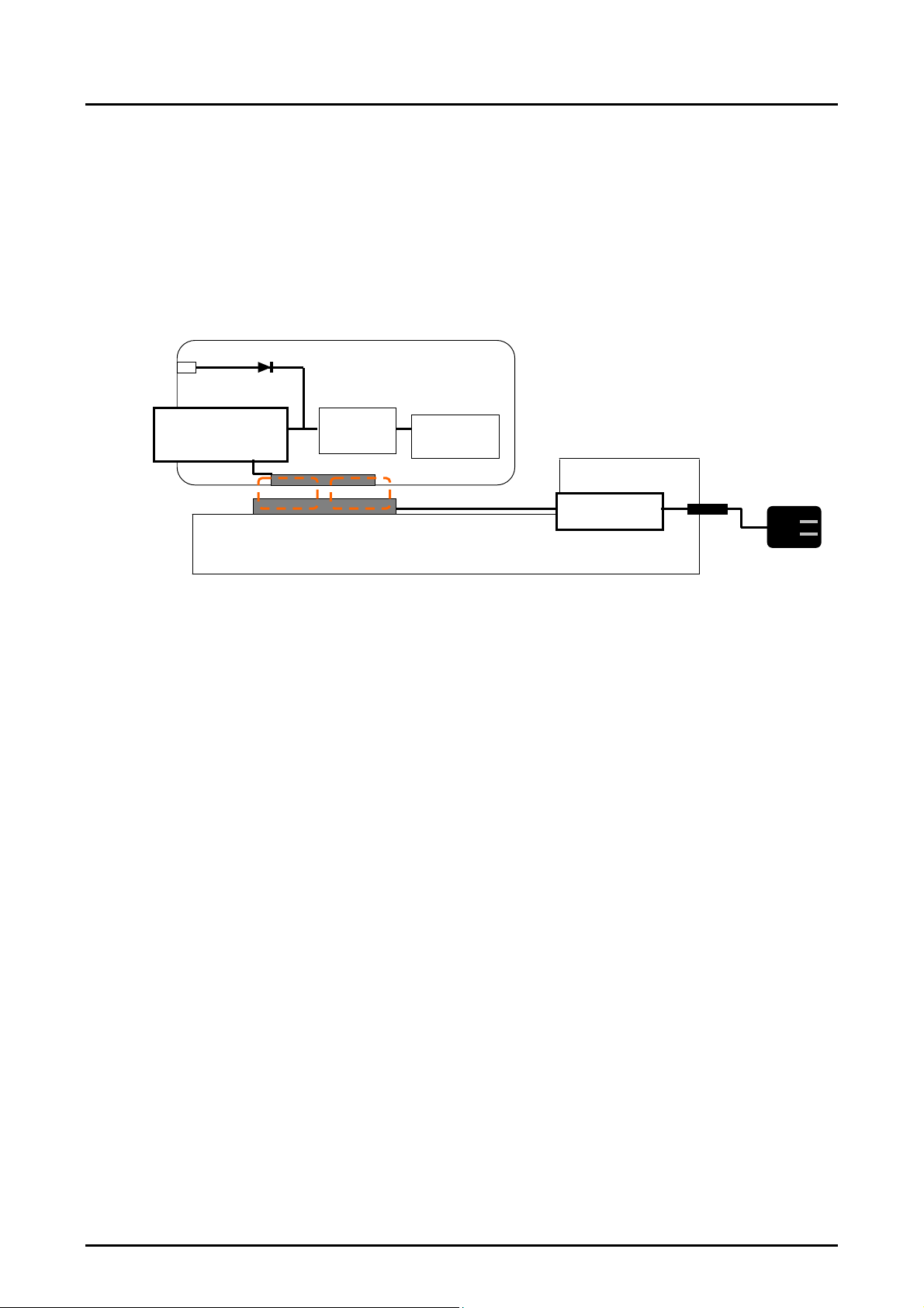
2.1 System Configuration
System Configuration
2.1.1
The following diagram shows an example of system configuration for the noncontact power transmission
modules.
Connector
for external
power supply
Secondary circuit module
Rectification circuit
Control circuit
Voltage control
Secondar
Primary coil unit
Charge
control
circuit
coil unit
Flux
Secondary
battery
Primary circuit module
Control circuit
Driving circuit
Fig.1 Example of System Configuration
AC Adapter
S4E16400/S4E16401 Technical Manual EPSON 3
(Rev.1.1)
2. SPECIFICATIONS
A
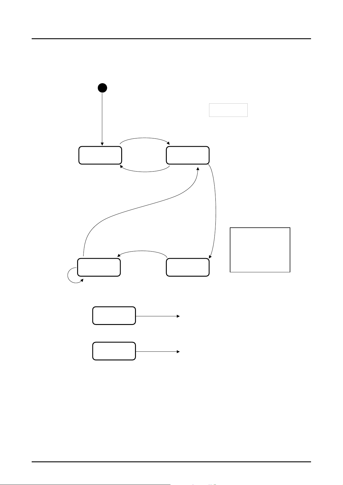
The operation of modules on the primary side and the secondary side must satisfy overall specifications
described in Section 2.4. Operations sequence is specified in the same section, whereas the system operation
sequence of Start - Charge - Finish is as outlined in the following:
(1)Standby
E:Battery voltage < Recharge
voltage (Battery has dropped)
(4)Save mode
E:Battery voltage ≥ Recharge voltage
A:Initialization
Starts intermittent output 1
E:Landing detection
(The secondary module has been placed on the top of the
primary module)
(2)ID exchange
E : ID exchange fail
E : Fully charged (Charging has been completed)
A : Starts intermittent output 2
Any state
E: Removal (The secondary module has been
removed from the primary module)
A: Stops transmission
Any state
E: Foreign object detection (Foreign metal object has
been detected)
: Stops transmission
(3)Charging
Fig.2 Sequence (Outline)
(1) To standby
(1) To standby
E:Event
A:Action
E:ID exchange succeeds
A:Starts serial output
Starts charging (Charging process begins)
Intermittent output 1:
interval = 300 mS approx.
(Standby)
Intermittent output 2:
Interval = 5 S approx.
(Save mode)
4 EPSON S4E16400/S4E16401 Technical Manual
(Rev.1.1)

2. SPECIFICATIONS
2.2 Specifications of Secondary Module
Overview of Specifications
2.2.1
This chapter describes the specifications of the primary module (module on the primary side) that belongs to
the noncontact power transmission modules.
The main function of the primary module is to convert power supplied by AC adapter into magnetic energy
and transmit it to the secondary module (module on the secondary side).
The module has the following functions allowing for safety charging process.
♦ Detection of foreign metal objects
♦ Detection of abnormal temperature
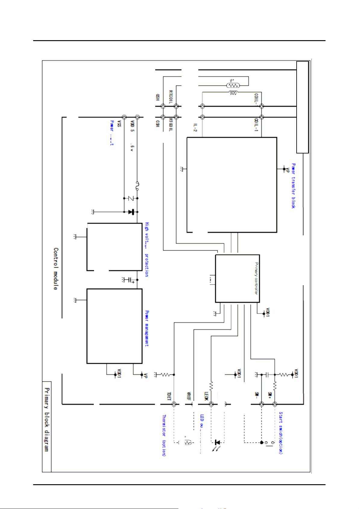
Block Diagram
2.2.2
The block diagram of the primary module is shown in the next page. The primary module consists of (1) Coil
unit and (2) Circuit module, and the following explains each of the functional blocks.
(1) Primary coil unit
♦ Coil and magnet sheet for inducing electromagnetic field
♦ Thermistor for detecting abnormal temperature
(2) Primary circuit module
♦ Control IC IC specifically for the module (S1F8811) manufactured by Seiko Epson
♦ Driving block Switcing driver consisting of power MOSFET family.
♦ Overvoltage protection block Overvoltage protection circuit for input voltage using a
voltage monitoring circuit and transistor
♦ Power management block Generates VDD1 power supply for control IC and VP power
supply for driver.
S4E16400/S4E16401 Technical Manual EPSON 5
(Rev.1.1)
2. SPECIFICATIONS
P
i
y
bl
k
di
g
p
(
p
)
(
p
)
r
g
p
A
A
VDD1
tion
o
Start switch
SW+
VDD1
tion
o
ut
ram
a
LED out
UTO
SW-
VDD1
LED
LEDK
VREF
Thermistor (option)
oc
TDET
VP
VDD1
ement
Power mana
mar
r
8M
Primary controle
Control module
High voltage protection
VP
Power transfer block
ut
CSH
COIL-1
COIL-2 COIL-2
RTCOIL
VDD 5.2 to 5.6V
VSS
Power in
COIL-1
6 EPSON S4E16400/S4E16401 Technical Manual
CSH
RTCOIL
Coil unit
(Rev.1.1)

2. SPECIFICATIONS
2.2.3 Pin Description
Pin Description Table for Primary Coil Unit (4 pins Connector)
No. Pin Name Description
* RTC
1
2 SH A thermistor pin. Connect this with the CSH pin on the circuit module connector -2.
3 COIL-2 A coil connection pin. Connect this with the COIL-2 pin on the circuit module connector -2.
4 COIL-1 A coil connection pin. Connect this with the COIL-1 pin on the circuit module connector -1.
Pin Description Table for Primary Circuit Module
Connector - 1
No. Pin Name In/Out Description
1 VDD I Power pin
2 VSS I GND pin
Connector - 2
No. Pin Name Description
1 COIL-1 A coil connection pin. Connect this with the COIL-1 pin on the coil unit.
2 COIL-2 A coil connection pin. Connect this with the COIL-2 pin on the coil unit.
3 SH A thermistor pin. Connect this with the CSH pin on the coil unit.
* RTC
4
Pins for Soldering -1
No. Pin Name In/Out Description
1 VDD
2 VSS
3 SW+ I
4 SW- O
5 AUTO I When selecting SW mode, short between this pin and SW-.Leave this pin open for
6 LEDA
7 LEDK
8 VREF
9 TDET
A thermistor pin. Connect this with the RTCOIL pin on the circuit module connector -2.
A thermistor pin. Connect this with the RTCOIL pin on the coil unit.
-
-
-
-
-
-
Power pin
GND pin
When SW mode is selected, install a momentary switch between SW+ and
SW-.When auto-start mode is selected, leave these pins open.
auto-start mode.
For driving the LED used for displaying primary module status.
External thermistor can be added. Leave these pins open when no external
thermistor is used.
S4E16400/S4E16401 Technical Manual EPSON 7
(Rev.1.1)

2. SPECIFICATIONS
Pins for Soldering -2
No. Pin Name In/Out Description
1 TEST1
2 TEST2
3 TEST3
4 TEST4
5 TEST5
6 TEST6
Absolute Maximum Ratings
2.2.4
Item Symbol Standard Unit Remarks
Supply voltage VDD -0.3 to +7.0 V
Input current Iin Max. 800 mA
Input pin voltage Vin -0.3 to +7.0 V
Performance assurance
temperature
Operating humidity Hop Max. 90 %RH
Storage temperature Tst -20 to +60
Storage humidity Hst Max. 90 %RH
[Caution] Using with a condition exceeding the above absolute maximum rating may result in malfunction or
unrecoverable damage. Moreover, normal function may be achieved temporarily but its reliability
may be significantly low.
Electrical Characteristics
2.2.5
The following describes the electrical characteristics of the primary circuit module.
Item Symbol Conditions Min. Typ. Max. Unit
Supply voltage VDD 5.2 5.4 5.6 V
Input current Iin 700 mA
Standby power Pstb Excluding AC adapter 50 mW
Low input voltage
detection
Transmission frequency F1 During power transmission 121.21 kHz
Transmission frequency
Transmission frequency
[Caution] Do not use the product over the range of the power voltage or input current. The authentication
function and various detection functions may not properly operate and cause a functional failure.
[Caution] Only the coil unit specified by Epson must be connected for use. When using a coil unit or circuit
module other than specified, or using a modified coil unit or circuit module, safety and other
functions may not operate normally. Using such items results nonconformity of technical standards
related to the radio law.
-
-
-
-
-
-
Test pin. Leave this pin open.
Test pin. Leave this pin open.
Test pin. Leave this pin open.
Test pin. Leave this pin open.
Test pin. Leave this pin open.
Test pin. Leave this pin open.
Top -10 to +45
Vlow
F2
F3
For continuous 5 sec.
During authentication
(Approx. 500 msec)
During detection of a foreign
material (including a metal)
(Approx. 1 msec)
°C
°C
3.8 4.0 4.2 V
129.03 kHz
114 kHz
8 EPSON S4E16400/S4E16401 Technical Manual
(Rev.1.1)
2. SPECIFICATIONS
Electrical Characteristics of Primary Coil Unit
Item Symbol Condition Min. Typ. Max. Unit
Inductance L1c 19.6 uH
Resistance R2c 203
Functional Description
2.2.6
The following describes the functions of the primary module.
Item Description
Detection of landing Monitors intermittently to check whether the secondary module is placed on the top
of the primary module.
Fig. 3 shows the timing of the landing detection.
Detection removal Detects removal of the secondary module from the primary module, and enters
standby status.
Authentication Reciprocal process of authentication between the primary module and secondary
module. The process ensures that the power transmission is permitted only between
the predefined combination. The authentication procedure will be defined
separately.
Detection of foreign metal
objects
Detection of foreign metal
objects
Monitors constantly to check whether any foreign metal object is inserted. If
detected, the module stops power transmission. However some metals objects may
not be detected depending on the method of embedding the module into chassis or
characteristics of the object. Therefore, this function is not assured to detect every
bit of the foreign objects. After the foreign metal object is removed, the module
resumes the initial state.
Detects the temperature of the center of coil, and when it becomes 70 °C or higher,
stops the power transmission. Power-on reset is required to resume the
transmission.
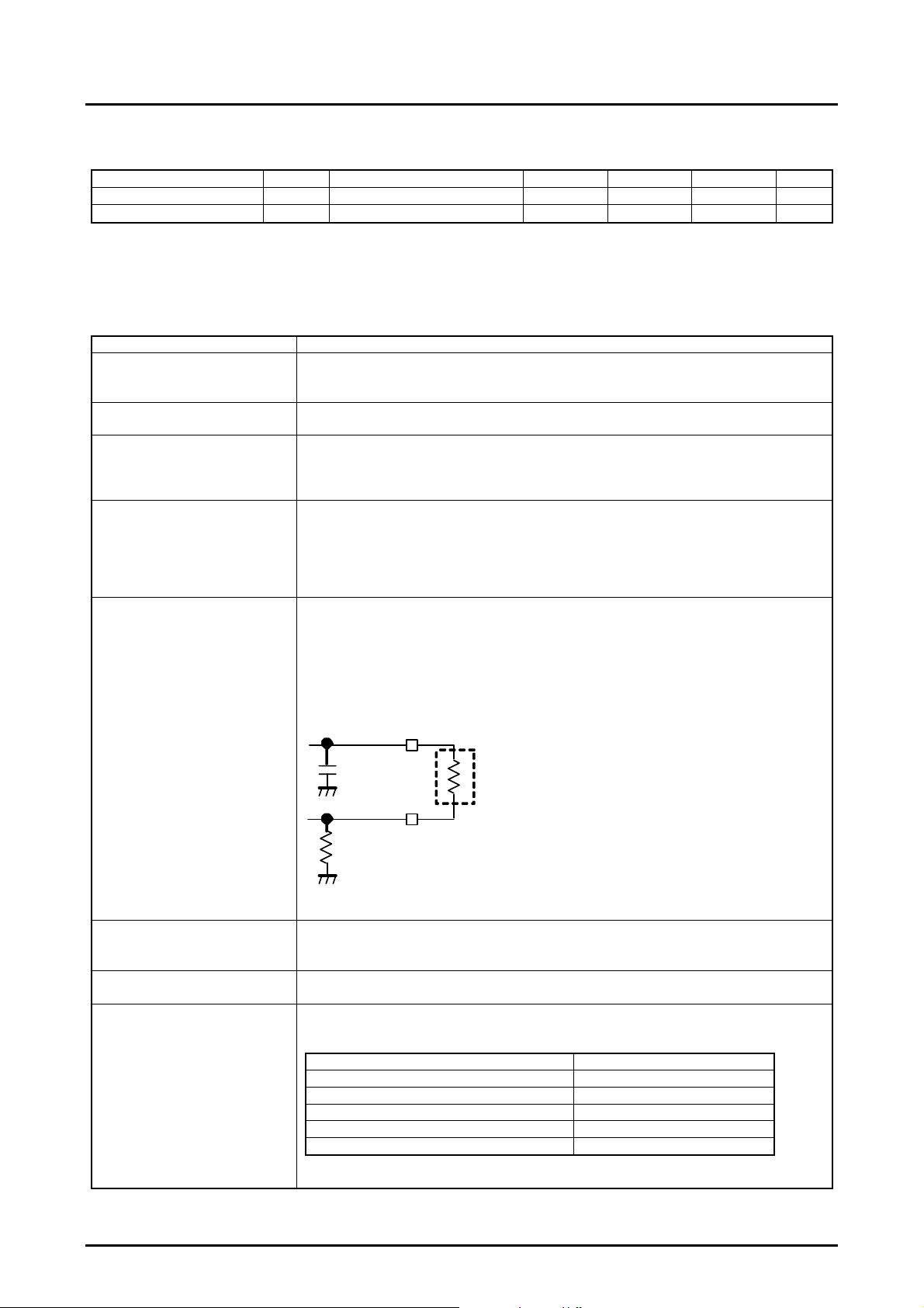
Installing thermistor between VREF and TDET as shown in the following diagram
enables you to detect temperature at any position.
Detected temperature: 60°C (absolute temperature, recommended component is
used)
VREF
mΩ
1000pF
TDET
RT
External
100KΩ
Recommended component
Murata Manufacturing NCP15WF104F03RC (100KΩ ±1%/4250K±1%)
Overvoltage protection Stops power supply to the subsequent overvoltage protection blocks immediately
when input voltage exceeds 6.2 ± 0.2V.When the input voltage returns to normal
level, the module resumes the initial state.
Detection of low voltage Stops power transmission when input voltage drops below 4.0 V during the
transmission. Power-on reset is required to resume the transmission.
Detection of low voltage Can display the state of primary module by connecting LED with the LEDA and
LEDK pins.
State LED
Standby Off
During power transmission On
Standby after fully charged Off
When detecting abnormal temperature Blinking
When detecting low voltage Blinking
S4E16400/S4E16401 Technical Manual EPSON 9
(Rev.1.1)

2. SPECIFICATIONS
線
2.2.7 Embedding Conditions
This section describes conditions required to embed the primary module.
To connect the primary coil unit and the primary circuit module, be sure to use the cable with specifications
shown in the following (1) or (2).
[Caution] If cables having different specifications are used, they may violate the technical standards related to
Transmission circuit drives
Transmission circuit stops
Driving time for detecting
landing 5ms
(1)
(2)
the radio law.
(Time)
Interval time
325ms
Fig.3 Landing Detection Timing
コネクタ:JST 社製 型番 SHR-04V-S
Connector: Model number SHR-04V-S manufactured by JST
:AWG#28
Line: AWG#28
50 ± 3mm
110 ± 3mm
Fig.4 Specification of Cable
10 EPSON S4E16400/S4E16401 Technical Manual
(Rev.1.1)

2. SPECIFICATIONS
y
f
The following shows an example of embedding the primary coil unit.
2.8 ± 0.2mm (*1)
Primar
coil - Surface of cradle
(*1) Reference value. Will be
defined separately in view o
probable generalization and
compatibility.
Temperature
detection element
Magnet sheet
25 mm or more for metal
chassis
Primary coil
Fig.5 Section of Primary Module (Coil Unit)
x Material
Resin must be used for the material of chassis.
[Caution] In order to prevent the temperature detection element from being damaged by shock, consider
installing “escape” on a chassis or other solution when designing the chassis.
2.3 Specifications of Secondary Module
Overview of Specifications
2.3.1
This chapter describes the specifications of circuit on the secondary side that belongs to the noncontact power
transmission modules.
The main function of the circuit on the secondary side is to convert flux supplied from the primary module
into direct-current power and supply it to the charge control circuit.
The circuit also has the function of detecting fully charged state for the purpose of power saving, as well as
the recharging function.
Block Diagram
2.3.2
The block diagram of the circuit on the secondary side is shown in the next page. The secondary module
consists of (1) Coil unit and (2) Circuit module. The following explains each of the functional blocks.
(1) Primary coil unit
♦ Coil and magnet sheet for inducing electromagnetic field
(2) Secondary circuit module
♦ Control IC IC specifically for the module (S1F8820B) manufactured by Seiko Epson
♦ Rectification unit Rectification circuit
♦ Load modulation unit For transmit information to the primary side.
♦ Voltage control unit For regulating output voltage.
♦ Output control unit Output gate using power MOSFET.
S4E16400/S4E16401 Technical Manual EPSON 11
(Rev.1.1)

2. SPECIFICATIONS
AC adaptor input
Output Control
VDD
Charger circuit
VOUT+
Battery
Charger circuit
Secondary block diagram
VOUT-
ACIN(input)
Power output
LEDRI(input)
Full charge detector
AC adapter detect
VDD
Load reduce signal
ICUT (output)
VBAT (input)
Battery voltage detect
LED Indicator (N-ch Open drain)
LEDRI(output)
Rectifier Load modulation Voltage regulation
Secondary controller
Control module
COIL-1
COIL-2
COIL-1
COIL-2
Coil unit
12 EPSON S4E16400/S4E16401 Technical Manual
(Rev.1.1)

2. SPECIFICATIONS
2.3.3 Pin Description
Pin Description Table for Secondary Coil Unit (Pins for Soldering)
No. Pin Name Description
1 COIL-2 A coil connection pin. Connect this with the COIL pin on the circuit module.
2 COIL-1 A coil connection pin. Connect this with the COIL pin on the circuit module.
Pin Description Table for Secondary Circuit Module (20 Pins Connector)
No. Pin Name In/Out Description
1,3 COIL1 I
2,4 COIL2 I
5,6,7,8 NC
9,10 VOUT+ O DC output (+)
11,12 VOUT- O DC output (-)
13 ACIN I
14 VBAT I
15 ICUT O A load reduction signal used for periodical authentication.
16 LEDRI I A full charge detection pin. Charging process is determined to be completed
17 TEST1 - Test pin. Connect this with VOUT-.
18 TEST2 - Test pin. Connect this with VOUT-.
19 LEDG O For outputting the state of the secondary module.
20 NC - A NC pin. Leave this pin open.
-
(*) For the coil connection pin, the coil connection land (2 positions) that supports soldering can be used in
addition to the 20 pins connector.
A coil connection pin. Connect this with the COIL pin on the coil unit.(*)
A coil connection pin. Connect this with the COIL pin on the coil unit.(*)
A NC pin. Leave this pin open.
An AC adapter detecting pin. Output from VOUT ± is stopped when AC adapter
is detected. Leave these pins open if the function of detecting AC adapter is not
used.
A battery voltage monitoring pin. Leave this pin open if the recharging function is
not used.
when H level state continues for 5 seconds, and the module enters full charge
standby state. Connect this pin with VOUT- if the function of detecting full
charge state is not used.
State Output
During power output L level (-10 mA max.)
During stop of power output Open
S4E16400/S4E16401 Technical Manual EPSON 13
(Rev.1.1)

2. SPECIFICATIONS
2.3.4 Absolute Maximum Ratings
Item Symbol Standard Unit Remarks
Input pin voltage Vin Vout - -0.3 to Vout + +0.3 V VBAT, LEDRI, ACIN
Performance assurance
temperature
Operating humidity Hop Max. 90 %RH
Storage temperature
Storage humidity Hst Max. 90 %RH
Top
Tst
[Caution] Using with a condition exceeding the above absolute maximum rating may result in malfunction or
unrecoverable damage. Moreover, normal function may be achieved temporarily but its reliability
may be significantly low.
Electrical Characteristics
2.3.5
The following describes the electrical characteristics of the secondary circuit module.
Item Symbol Conditions Min. Typ. Max. Unit
Output voltage Vout unloaded 4.9 5.2 5.5 V
Output voltage ripple Loaded with 100 mA 100 mV
Voltage detected by LEDRI VLEDRI 2.2 2.5 2.8 V
ICUT output current
Detected voltage by ACIN VACIN 4.0 4.1 4.2 V
Detected voltage by VBAT VVBAT 3.8 3.9 4.0 V
LEDG current ILEDG -6 mA
I
ICUTH
I
ICUTL
[Caution] Only the coil unit specified by Epson must be connected for use.
[Caution] Do not connect a load that drops Vout to 3V or less. Doing so may cause secondary circuit
module to reset.
Electrical Characteristics of Secondary Coil Unit
Item Symbol Conditions Min. Typ. Max. Unit
Inductance L2c 11.68 uH
Resistance R2c 196
-10 to 45
-40 to 80
With maximum load
ICUT=Vout-0.1V
High, V
ICUT=0.1V
Low, V
°C
°C
150 mV
0.2 mA
0.3 mA
mΩ
14 EPSON S4E16400/S4E16401 Technical Manual
(Rev.1.1)

2. SPECIFICATIONS
Output Voltage - Current Characteristics
The following shows the characteristics of output voltage to output current. The characteristics vary greatly
depending on positional relation between coils on the primary side and the secondary side. If you consider a
design with large deviation, therefore, be sure to check whether the design can supply necessary power.
When you determine the location where the power greater than the 4.5V voltage and 400mA current can be
output, refer to Section 2.4.6 "Embedding Conditions".
Output V-I curve
6
5.5
5
4.5
4
3.5
3
2.5
2
Output voltage Vout(V)
1.5
1
0.5
0
0 100 200 300 400 500 600
(*)
upper
lower
Output current Iout(mA)
[Conditions] Input power : Vin=5.4V Iin≤680mA, Positional deviation: z=3.3 to 4.3mm / x=0.0 - 5.0mm
(*) Do not use in a Vout < 3.0V condition. Doing so may cause the control circuit on the secondary side to
reset.
Fig.6 Output Voltage and Current Characteristics
Functional Description
2.3.6
This section describes functions of circuit on the secondary side.
Item Description
Stops power supply to the charge control circuit by turning the LEDRI pin L ≥ H
Detection of fully charged state
Recharge function
Detection of AC adapter
Authentication
when fully charged state stops the charging process, and transmits the power save
mode command to the primary module. Connect the LEDRI pin with VOUT- if this
function is not used.
Starts recharging process if the battery voltage becomes recharge voltage (3.9 ±
0.1V) or less when the module enters power save mode due to fully charged state.
If this function is not used, leave the VBAT pin open.
Prioritizes AC adapter to supply power to the charge control circuit if the power is
currently supplied direct from the AC adapter. If this function is not used, leave the
VBAT pin open.
Reciprocal process of authentication between the primary module and secondary
module. The process ensures that the power transmission is permitted only
between the predefined combination. The authentication procedure will be defined
separately.
S4E16400/S4E16401 Technical Manual EPSON 15
(Rev.1.1)

2. SPECIFICATIONS
2.3.7 External Connection Examples (Reference)
Example of Application to Charging Circuit
[Caution] Circuit examples described above show connection examples for peripheral circuits of this product
and do not guarantee charging operation. Make a full evaluation on the actual application to select
parts. When you charge the battery, secure the service range and conditions recommended by the
battery manufacturer by detecting the battery condition (voltage, current, temperature) outside the
battery and build in protective circuits and control devices that operate when they detect a problem
to assure safety.
Embedding Conditions
2.3.8
This section describes examples of embedding the secondary module.
This product is designed on the premise of a metal shield being placed on the top of the secondary coil
unit.Place an aluminum, copper or another metal sheet with the size of approx. 35 × 35 mm on a position 0 to 5
mm away from the surface of the secondary coil unit. If the metal shield and the battery pack are not mounted,
the accuracy of the foreign metal detection function drops. Also, if a metallic housing or another metallic or
magnetic part is placed in the non-metal area of Figure 8, the leaked flux is absorbed by those metals and the
authentication range may become smaller. If the leaked flux is absorbed by the metal, the input current to the
primary module increases. Therefore, you can determine whether the leaked flux is absorbed by the metal or not
by simply measuring an increase of input current to the primary module without connecting the secondary
module to a load. The following shows the permissible value of increased input current to the primary module
that does not affect on the authentication range.
You can also check the authentication range using the special jig.
Permissible value of increased input current to the primary module caused by shield and other metal (*): 5 15mA
(Vertical distance from the primary coil: 4.0 mm)
(Vertical distance from the primary coil: 0.0mm)
16 EPSON S4E16400/S4E16401 Technical Manual
(Rev.1.1)

2. SPECIFICATIONS
A
The following describes checking procedure when the top of the secondary coil unit is in situation (1) - (4) as
shown below.
(1) No metal, (2) Battery pack, (3) Circuit board, (4) Metal or magnetic component
(1) When no metal is placed on the secondary coil unit
OK
(2) When a battery pack is placed on the secondary coil unit.
OK
Measure input current I1 to the primary module at
the (X, Z) = (0, 4) position and without any load
Measure input current I2 after affixing a 35 × 35
(mm) aluminum sheet to the secondary coil unit.
Yes
Adjust the aluminum sheet, and affix it to the
secondary coil unit then measure input current I2.
Measure input current I1 to the primary module at
the (X, Z) = (0, 4) position and without any load.
Place the battery pack at the same distance of an actual
equipment from the secondary coil unit, and measure
input current I2.
Yes
djust the position of the battery pack, and
measure input current: I2.
5≤I2-I1≤15mA?
No
5≤I2-I1≤15mA?
No
S4E16400/S4E16401 Technical Manual EPSON 17
(Rev.1.1)

2. SPECIFICATIONS
A
A
A
c
t
(3) When a circuit board is placed on the secondary coil unit.
OK
(4) When metal or magnetic component is placed on the secondary coil unit.
Measure input current I1 to the primary module at the (X,
Z) = (0, 4) position and without any load
ffix an A x A (mm) aluminum sheet to the secondary coil unit, and place
the circuit board at the same distance of an actual equipment from the
secondary coil unit, and then measure input current I2.
Yes
djust the aluminum sheet, and affix it to the secondary
coil unit then measure input current I2.
(Measure input current I1 to the primary module at
the (X, Z) = (0, 4) position and without any load.
Place the metal or magnetic component at the same distance of an
actual equipment from the secondary coil unit, and measure inpu
current I2.
OK
Yes
component, and measure input current: I2.
5≤I2-I1≤15mA?
No
5≤I2-I1≤15mA?
No
djust the position and size of the metal or magneti
18 EPSON S4E16400/S4E16401 Technical Manual
(Rev.1.1)

2. SPECIFICATIONS
The secondary coil unit and the secondary circuit module must be connected using a 50 to 200-mm long wire
lead or conductive pattern.
0 - 5mm
Secondary coil - Surface of cradle
Satisfies requirements in overall
specifications described in section 2.4.5
Fig.7 Section of Secondary Module (Coil Unit)
x Material
Resin must be used for the material of chassis.
Secondary coil unit
Metal shield
25mm
Primary coil unit
68mm
Metal-free area
Fig.8 Metal-Free Area
[Caution] The description in Section 2.3.8 may be subject to change.(The specification is not final.)
Metal shield
Magnet sheet
Secondary coil
S4E16400/S4E16401 Technical Manual EPSON 19
(Rev.1.1)

2. SPECIFICATIONS
2.4 Overall Specifications
Overview of Specifications
2.4.1
This chapter describes the overall specifications of the primary module (a module on the primary side) and
the secondary module (a module on the secondary side), consisting of the noncontact power transmission
modules.
The primary module drives intermittently while in standby state to keep detecting the landing of the
secondary module. If the primary module detects the secondary module, they execute reciprocal authentication
to ensure that they are the predefined combination permitted for the power transmission. If they pass the
authentication process, then the transmission can begin.
When the secondary module detects the fully charges state, it communicates with the primary module to enter
save mode, and shifts itself to save mode. If the secondary module maintains the landing state, the secondary
module detects that the battery voltage drops below the voltage defined to start recharging, and transmits the
information to the primary module to start recharging. If the recharging function is not used, the secondary
module continues to wait for the detection of removal.
During charging process, the secondary module reduces load periodically, and the primary module checks
whether the eddy-current loss occurs on the secondary side, caused by foreign metal objects. If any foreign
metal object is detected, the primary module stops power transmission.
Functional Description
2.4.2
The following describes the functions available when the primary module and the secondary module are
combined.
Item Description
Authentication Reciprocal process of authentication between the primary module and secondary
module. The process ensures that the power transmission is permitted only between
the predefined combination. The authentication procedure will be defined separately.
Transmission monitoring Monitors constantly to check whether any foreign metal object is inserted. If detected,
the power transmission is stopped. For this purpose, the secondary module reduces
load periodically, and the primary module checks whether the eddy-current loss occurs
on the secondary side, caused by foreign metal objects. However some metals objects
may not be detected depending on the method of embedding the module into chassis or
characteristics of the object. Therefore, this function is not assured to detect every bit of
the foreign objects.
Transmission monitoring
2.4.3
The noncontact power transmission module uses the following detection method assuming that metal objects
may erroneously be inserted into transmitter area during transmission. The secondary module enters unloaded
state at the timing shown in the following diagram, and flows load modulation current for a certain period of
time. The primary module monitors that load is changed between low and high state periodically. For example,
the primary module determines the eddy-current caused by foreign metal objects by detecting in low state the
higher load than standard value. When the primary module detects a foreign object, it stops transmission and
enters standby state.
The output current from the secondary module must be synchronized with the output from the ICUT pin of
secondary control IC (see the secondary circuit block diagram), and it must be above 5mA (inclusive) but below
40 mA (inclusive) in the low load state.
20 EPSON S4E16400/S4E16401 Technical Manual
(Rev.1.1)

2. SPECIFICATIONS
Load reduction
signal
(ICUT)
Load reduction
signal
(ICUT)
Load current
Load modulation
H
L
Low load time
416clk(3.43mS)
H
L
Normal load
5mA to 40mA
ON
OFF
Normal load time
151512clk(1250mS)
16clk(132µS)
200clk(1.65mS)
Fig.9 Transmission Monitoring Timing
(Time)
Normal load time
151512clk(1250mS)
Transmission frequency:121.21KHz
S4E16400/S4E16401 Technical Manual EPSON 21
(Rev.1.1)

2. SPECIFICATIONS
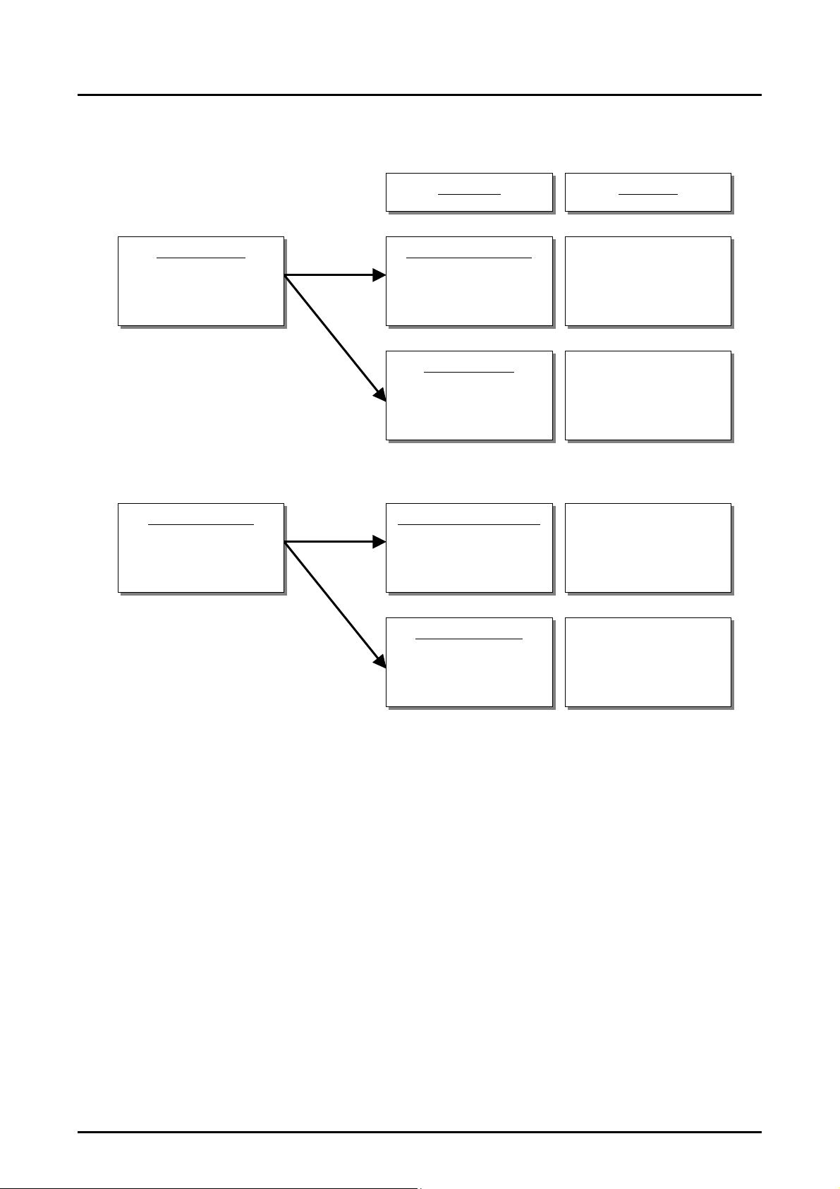
2.4.4 Sequence
This section describes the operations sequence of the noncontact power transmission modules.
However, ID code system will be defined separately because it will include items that should be handled as
confidential.
The following state transition diagrams show the sequence of the primary module and of the secondary
module.
22 EPSON S4E16400/S4E16401 Technical Manual
(Rev.1.1)

2. SPECIFICATIONS
A
A
E:Timer 300 mS approx.
A:Transmits power 5 mS (detects landing)
E:ID code NG
Detects foreign object
:Stops transmission
E:Timeout
A:Stops transmission
E:Receives VBAT response command
(Vbat =< recharge voltage)
A:Stops transmission
Clears SAVE_f
E:Receives VBAT response
command
(Vbat > recharge voltage)
A:Stops transmission
E:No removal x 64
E:Timer 5 s
A:Transmits power 40 mS
(detects removal)
(1)p Standby state
(2)p Negotiation
state
(3) p Setup state
E:Receives start command (SAVE_f=1)
A:Sends VBAT command
(6)p Fully charged
standby
state
Any state error
(4) p "Determine
command" state
E:Receives save command
A:(LED is OFF)
Stops transmission monitoring
Stops removal detection
Stops transmission
Sets SAVE_f
E:Abnormal temperature/A:Stops transmission
Fig.10 Primary Module
E:Power-ON
A:System reset
Clears all flags
E:Detects landing
A:Starts serial transmission
E:Receives secondary ID code
A:Sends primary ID code
E:Receives setup command
A:Sends setup command (result)
(5)p Power
transmission state
End
E:Event
A:Action
E:Receives start command (SAVE_f=0)
A:Sends start charging command
E:Receives response to start charging command
A:(LED is ON)
Starts transmission monitoring
Starts removal detection
Starts charging transmission
E:Detects foreign object
:(LED is OFF)
Stops start transmission
Stops removal detection
Stops transmission
S4E16400/S4E16401 Technical Manual EPSON 23
(Rev.1.1)

2. SPECIFICATIONS
E: Timeout
A:
E: Timer 1 s
A: Sends save command
E: Timeout
A:
(5) s “Determine
recharge” state
(7) s Fully charged
state
Any state
Fig.11 Secondary Module
Initialization
Clears all flags
(1) s Standby state
(2) s ID exchange
state
(3)s Setup state
E: Receives VBAT command
A: Measures VBAT
Sends VBAT response command
E: Fully charged (LEDRI)
A: Stops transmission monitoring
Closes output gate
Sends save command
E: Detects AC adapter
A: Closes output gate
Sets AC_f
E: Voltage level OK
A: Sends secondary ID code
E: Receives primary ID code
A: Sends setup command
E: Receives setup command
(result)
A: Sends start command
(4) s “Determine
command” state
(6) s Power
transmission state
(1)To: s Standby state
E: Timer 30 mS
A: Opens output gate
Starts detecting full
charge
E: Receives start charging command
A: Sends response to start charging
command
Starts transmission monitoring
24 EPSON S4E16400/S4E16401 Technical Manual
(Rev.1.1)

2. SPECIFICATIONS
Safety against Foreign Metal Objects
2.4.5
As this system uses electromagnetic induction for power transmission, metal placed on the primary coil may
generate heat due to induction heating. The following design is incorporated into the modules against heat
generation of metal.
<Before ID authentication>
If a foreign metal object placed before authentication is detected, the system does not execute authentication
process and does not start power transmission.
<After ID authentication>
If a foreign metal object inserted after the authentication and during power transmission is detected by the
primary side, the system stops transmission and execute authentication process again. A metal object with
material and size that cannot be detected before and after the authentication must not rise its temperature higher
than 55 deg C under room temperature (25°C).
[Caution] The detecting ability may vary depending on the condition that the module is built on the product.
Make a full evaluation on it and check that there is nothing inconvenient before using. If it doesn’t
properly detect foreign matters, they may generate heat due to induction heating and reach
dangerous temperature.
[Caution] The detecting ability is not assured to detect all heat generating metals. Add safety circuits if
necessary and secure safety before using.
S4E16400/S4E16401 Technical Manual EPSON 25
(Rev.1.1)

2. SPECIFICATIONS
2.4.6 Embedding Conditions
Output voltage on the secondary side depends on the position of primary coil unit and secondary coil unit.
Therefore the following defines the horizontal distance (X) and the vertical distance (Z) of the center of each
coil. Consider the following positional relation when you design a chassis for your product into which the coil
unit is embedded.
Item Recommended Value Allowable value
Transmission distance (vertical distance) 4.0mm See Figure 12.
Deviation of the center of coil (to horizontal) 0.0mm See Figure 12.
Distance between coils:Z(mm)
6.0
(X,Z)
5.0
(5.0,4.3)
4.0
(5.0,4.3)
(5.0,3.3)
7.0 1.0 2.0 3.0
6.0 0.0
5.0
4.0
3.0
2.0
1.0
1.02.03.0
Allowable range for authentication
and 4.5 V/400 mA output
4.0
(5.0,3.3)
5.0 6.0 7.0
Deviation of Center of Coil: Z (mm)
Fig.12 Allowable Range for Authentication and 4.5 V/400 mA Output
(Deviation of position between the primary coil unit and secondary coil unit.)
[Caution] The value shown above may vary depending on the condition that the module is built on the
product. Make a full evaluation on it and check that there is nothing inconvenient before using
26 EPSON S4E16400/S4E16401 Technical Manual
(Rev.1.1)

2. SPECIFICATIONS
f
t
Secondary coil uni
3.3 – 4.3mm
2.8mm is
recommended
Primary coil unit
Fig.13 Section of Primary Coil Unit and Secondary Coil Unit
[Caution] The description in Section 2.4.5 may be subject to change.(The specification is not final.)
5mm max.
Deviation of the center o
coil
S4E16400/S4E16401 Technical Manual EPSON 27
(Rev.1.1)

3. EXTERNAL DIMENSIONS
3. EXTERNAL DIMENSIONS
The following diagrams are attached to this document.
♦ Module on the primary side S4E164000010000 Product diagram
28 EPSON S4E16400/S4E16401 Technical Manual
(Rev.1.1)

3. EXTERNAL DIMENSIONS
♦ Module on the secondary side S4E164010010000 Product diagram
S4E16400/S4E16401 Technical Manual EPSON 29
(Rev.1.1)

4. PRECAUTIONS
4. PRECAUTIONS
4.1 General precautions
♦ This product is designed and manufactured for general consumer use and is not designed for an
application for any life-support or other devices that require a very high degree of reliability. We are
not responsible for any results caused by the use of this product or those devices for such application.
♦ The content of this document is subject to change without prior notice.
♦ Neither a part or the whole of this document may be transferred, reproduced, or used for any other
purpose without our permission
♦ Application circuits, programs and usage contained in this document are reference information. We do
not provide any guarantee on the right (including intellectual property right and know-how, hereafter
intellectual property) of a third party infringement or generation of damage. This document may not
be construed as granting anyone a license of the intellectual property right of us or any other third
parties.
♦ Characteristics, large and small, indicate magnitude relationships on the number line.
♦ Of the products referred to in this document, the export of those falling under the strategic material
category stipulated in the Foreign Exchange and Foreign Trade Control Law shall require the granting
of an export license according to said law.
♦ The warranty period of this product is one year after shipment of the product. Though we shall be
responsible for replacing the product due to a trouble within the scope of this specification, we shall
not be liable for other damages. We do not guarantee products for which 1 year has passed since the
shipment.
4.2 Precautions on Handling
♦ Provide full safety measures to the system and devices using this product.
♦ Metal placed on the primary coil may generate heat due to induction heating. We recommend that you
describe the following points in the instruction manual and the finished product case.
( Do not place other products than the specified secondary products on the primary side. They
♦ Do not allow input exceeding the maximum rating and DC characteristics. It can cause troubles of
♦ Some adapters may generate a noise. In this case, install a ferrite core to prevent it.
♦ As transmission characteristics of a noncontact power transmission module changes due to the usage
♦ If you find a trouble such as smoke, abnormal smell and overheating during operation (charging) and
♦ Be careful of the following when you install a module.
may cause heat and a trouble.
( Do not place metal such as coins and clips on the primary product (charger) when they are
live and on standby as they are in danger of generating heat.
various detecting functions including generation of overheat and detection of foreign matters,
authentication function and permanent damage. We recommend that you describe the following points
in the instruction manual and the finished product case.
( Manufacturer providing built-in finished products) Use the specified AC adapter.
( Using other ones than is specified can cause heat, smoke and a trouble.
Example of taking measures: Ferrite core Kitagawa Kogyo RFC-8 3 turns Mounting location: Near the
module
environment (size of the housing, material, phase position of the primary and secondary coils,
environment with metal parts) of this module, we cannot guarantee operation in all usage environments.
Check the operating condition and safety in the actual usage environment. Add protective circuits and
redundant circuits in necessary and secure safety before using.
standby, stop using it immediately.
¾ Install a module properly to the case device, jigs and tools in order not to add stress such as
30 EPSON S4E16400/S4E16401 Technical Manual
(Rev.1.1)

4. PRECAUTIONS
warpage and distortion. Generation of deformation, flaking and damage may cause a functional
trouble and imperfect condition.
¾ Be careful not to rub the coil with a sharp edge and damage it by rubbing it. Damage on the
insulating coating may cause a functional trouble and imperfect condition.
¾ Make a full evaluation on physical stress including deformation and shock with your product
before using.
¾ Design the layout so that the product may not be exposed to liquid leakage when you install this
module.
¾ Each module has a part where wiring is exposed such as a coil terminal. So take full care against
short-circuit to other parts or leak when you handle the unit.
¾ Be careful so that conductive material such as metal fragments may not enter and interfere with
the circuit area of this product. They may cause malfunction and damage.
¾ Water entered into this product can cause malfunction of instruments and damage. We do not
guarantee operation if condensation is caused.
¾ As this module may cause flaking, floating and lysis due to organic solvent, be careful enough to
wipe it using organic solvent.
¾ Use the material that desn’t generate high-voltage leak for the equipment, tools and workers and
make a ground when you assemble this module.
¾ We recommend that you assemble the module in the environment that is not directly exposed to
dust, corrosive gas, direct sunlight and strong ultraviolet where the temperature and humidity is
apprpriate.
♦ Do not use the product under the following environment.
¾ The place where corrosive gas is generated
¾ The place where strong eadio wave and magnetic force are generatedOutput characteristic, ID
authentication and various sensor functions may not properly operate
¾ The environment where strong shock and vibration are produced
¾ Do not put this product in a microwave and on an electromagnetic cooking device. It may cause
heat, smoke and a fire.
♦ Be careful of the following as this product emits radio wave.
¾ If you find this product causing radio wave interference with other wireless devices, use it apart
from them or turn off the power on the primary side to prevent radio wave interference.
¾ Do not place a magnetic cared near the product and have it caught by it. Magnetic data may be
lost.
¾ Turn off the power on the primary side near a electronic device that handles high control and faint
signals. Electronic devices amy malfunction. Check the effect by the radio wave interference
when you use the product for those device or use it near them.
Example ・・・Heart pacemaker, audiophone, fire alarm, automatic door and other
electro-medical apparatus
¾ Do not use the product in a medical institution and a aircraft. Turn off the power on the primary
side and abstain from the use of the product in a place where use of wireless devices is generally
restricted.
4.3 Precautions on radio laws and regulations
This product (module) is scheduled to support the following standards related to the radio law. If you
disassemble and modify this product, you may receive punishment based on nonconformity of standard of each
country. Never modify the product. Contact our sales division for the latest standard support status.
¾ Japan: Radio law enforcement regulations Article 100 paragraph one number one and Article 44
paragraph two (1)
¾ United States:.FCC Part 15 Subpart C
¾ Europe: (R&TTE member nations): EN300330-1V1.3.1 and –2 V1.3.1(Receiver class 3, Product
class 1, Duty class 4)
¾ Taiwan: Administrative Regulations on Low Power Radio Waves Radiated Devices
♦ Please handle this product or bult-in products according to regulations of the country to which you
export or put them on sale.
♦ Take note that you may need to take various procedures due to regulations for exporting and sales to
other countries than is specified.
S4E16400/S4E16401 Technical Manual EPSON 31
(Rev.1.1)

5. SATISFIED LAWS AND REGULATIONS
t
d
5. SATISFIED LAWS AND REGULATIONS
5.1 Japan
This product is compliant with the Radio law enforcement regulations article 100 paragraph one number one
and article 44 paragraph two (1). We recommend that you clearly specify describe notes on the following points
in the instruction manual of built-in products.
x This product is compliant with the Radio law enforcement regulations article 100 paragraph one
number one and article 44 paragraph two (1).
As this product is designed based on domestic regulations, use it only in Japan.
x
x
If you disassemble and modify this product, you may receive punishment based on
nonconformity of the Radio law enforcement regulations. Never modify the product.
( If you find this product causing radio wave interference with other wireless devices, use i
apart from them or turn off the power on the primary side to prevent radio wave
interference.
( Make an inquiry on the use of the product to the contact described below.
Carrier wave frequency 121.2kHz
Contact: To the company name providing the finishe
5.2 The United States of America
This product is compliant with the following standard.
Intentional radiation device standard FCCpart15 Subpart C
FCC ID: BKMDGE001
Attach the label showing the following contents to the built-in product.
“Contains Transmitter Module FCC ID: BKMDGE001” or “Contains FCC ID: BKMDGE001”
Precautions
FCC WARNING
Changes or modifications not expressly approved by the party responsible for compliance could void the
user’s authority to operate the equipment.
This transmitter must not be co-located or operated in conjunction with any other antenna or transmitter.
This device complies with Part 15 of the FCC Rules. Operation is subject to the following two conditions: (1)
this device may not cause harmful interference, and (2) this device must accept any interference received,
including interference that may cause undesired operation.
5.3 Europe (R&TTE member nations)
This product is compliant with the following standard.
Wireless device technical standard: EN300330-1 V1.3.1 and EN300330-2 V1.3.1
Receiver class 3
Product class 1
Duty class 4
R&TTE member nations (As of February, 2008)
Austria, Belgiumj, Bulgaria, Cyprus, Czech, Denmark, Estonia, Finland, France, Germany, Greece, Hungary,
Iceland, Italy, Lichtenstein, Lithuania, Latvia, Luxembourg, Malta, Netherlands, Norway, Poland, Portugal,
Slovakia, Slovenia, Spain, England, Rumania
32 EPSON S4E16400/S4E16401 Technical Manual
(Rev.1.1)

6. EXPORTING
科學及醫療用電波輻射性電機設備之干
5.4 Taiwan
This product (or module) is compliant with the “Administrative Regulations on Low Power Radio Waves
Radiated Devices” and “Low-power Radio-frequency Devices Technical Regulations (LP0002)”.
The following device handling instructions shall be followed.
Article 12. Without permission granted by the DGT, any company, enterprise, or user is not allowed to
change frequency, enhance transmitting power or alter original characteristic as well as performance to a
approved low power radio-frequency devices.
Article 14. The low power radio-frequency devices shall not influence aircraft security and interfere legal
communications; if found, the user shall cease operating immediately until no interference is achieved. The said
legal communications means radio communications is operated in compliance with the Telecommunications Act.
The low power radio-frequency devices must be susceptivle with the interference from legal communications or
ISM radio wave radiated devices.
We recommend that you clearly specify describe notes on the following points in the instruction manual of
built-in products.
Permission No.
低功率電波輻射性電機管理辦法
第十二條
第十四條
經型式認證合格之低功率射頻電機、非經許可、公司、商號或使用者均不得擅自
變更頻率、加大功率或變更原設計之特性及功能。
低功率射頻電機之使用不得影響飛航安全及干擾合法通信;經發現有干擾現象
時、應立即停用,並改善至無干擾時方得繼續使用。
前項合法通信、指依電信法規定作業之無線電通信。
低功率射頻電機須忍受合法通信或工業、
擾。
Example of the sentense:
CCAB08LPxxxOTY
6. EXPORTING
6.1 Notes on Exporting to US
The primary and built-in products of this product (module) fall under the category of intentional and
unintentional radiation devices regulated in US.Check that the product is compliant with the following
standards before exporting it for the sale in US.
♦ Required approval As of February, 2008
Finished devices embedded with this product require approval from FCC authorities concerned as
intentional and unintentional radiation devices. You need to have an official authentication authority
certify that the product conforms to the following standard to get a license.
(1) Intentional radiation device standard FCCpart15 Subpart C
(2) Unintentional radiation device standard FCCpart15 Subpart B
(3) Product Safety Standard UL standard (varies depending on the device)
Since this product has already acquired the certificate of conformance of (1), you do not need to aquire a new
certificate of conformance of (1) for finished goods containing this product (except for the case where a
technology to which the Intentional radiation device standard applies). You need to clearly describe notes on (1)
in the specified method on the finished goods or in the instruction manual.
S4E16400/S4E16401 Technical Manual EPSON 33
(Rev.1.1)

6. EXPORTING
r
FCC WARNING
Changes or modifications not expressly approved by the party responsible for compliance
could void the user’s authority to operate the equipment.
This transmitter must not be co-located or operated in conjunction with any other antenna o
transmitter.
This device complies with Part 15 of the FCC Rules. Operation is subject to the following two
conditions: (1) this device may not cause harmful interference, and (2) this device must accept
any interference received, including interference that may cause undesired operation.
Also, attach the label showing the following contents to the finished goods.
“Contains Transmitter Module FCC ID: BKMDGE001” or
“Contains FCC ID: BKMDGE001”
If you use a module for which certificate of conformance of (1) has been acquired by us, and you need the
certificate conformance, please contact with us accordingly.
Customers who sell finished goods need to acquire certificate of conformance as finished built-in goods for
(2) to (3). The information to be provided on the finished goods or in the instruction manual must follow the
applicable standards and regulations.
♦ (Unauthorized export) Regulations as of February, 2008
You can export up to 200pcs per model with the Form740 document (have it prepared by a US
importer and present it according to a request by an inspecter to pass customs) to export the product
for evaluation and exhibition. You need to acquire FCC ID to prepare Form740.
Post a notice to show that this product is not in conformity to the standard (example shown below) to
introduce and evaluate the product in public places such as an exhibition. You may need to make a
special application by the guidance of the regulating authority. Observe the guidance of the authority
in that case.
You may not export the product for the purpose of putting it on sale in US.
This device has not been authorized as required by the rules of the Federal Communications
Commission. This device is not, and may not be, offered for sale or lease, or sold or leased,
until authorization is obtained.
6.2 Notes on exporting to R&TTE member nations
The primary and built-in products of this product fall under the category of wireless devices regulated in
R&TTE member nations. Check that the product is compliamt with the following standards before exporting it.
♦ Required approval As of February, 2008
You can sell finished devices embedding this product as electric equipment with a wireless function
provided that you have acquired a CE mark.
You need to have an official authentication authority certify that the finished devices conform to the
following standard to get a CE mark.
(1) Wireless device technical standard EN300330-1 V1.3.1 and EN300330-2 V1.3.1
(2) Wireless device EMC standard EN301489-1 V1.6.1 and EN301489-3 V1.4.1
(3) Product safety standard (Example) EN60950-1 (appropriate standard selection by
application)
(4) Electric product leakage magnetic field standard EN50366 : 2003 version
(5) Home electric equipment EMC standard EN55014
(1) to (5) are standards required to acquire a CE mark as wireless devices or electric equipment with a
wireless function.
(1) The certificate of conformance of (1) is scheduled to be acquired by this product (module).
Customers who sell finished goods need to acquire certificate of conformance as finished built-in
goods for (2) to (5)
34 EPSON S4E16400/S4E16401 Technical Manual
(Rev.1.1)

6. EXPORTING
You do not need to aquire a new certificate of conformance of (1) for finished goods embedded with a
module for which certificate of conformance of (1) has been acquired. As the certificate of conformance of (1)
(such as the test report, technical documents, and other documents required to acquire the certificate of
conformance of customer's products) is required for application of CR markings, consult us for details.
You can use products compliant with all standards described above outside a car. Do not use it in a car. You
need to acquire an additional standard (ISO7637-1 and ISO7637-2) if you are supposed to use it in a car.
♦ Export before acquiring a CE mark As of February, 2008
You may not use the product to put it on the market in R&TTE member countries. Include
precautionary notes describing the following points and give users a guidance in advance before
exporting the product. Post a notice to show that this product is not in conformity to the standard in an
exhibition. You may need to make a provisional application by the guidance of the regulating
authority. Observe the guidance of the authority in that case.
This equipment falls under the category of wireless equipment. You may import the equipment for
experiment, research or display in an exhibition and may not use it for sales.
Example of the sentense:
This device has not been authorized as required by the rules of the Federal Communications
Commission. This device is not, and may not be, offered for sale or lease, or sold or leased,
until authorization is obtained.
♦ Export after acquiring a CE mark As of February, 2008
The following markings are required on the equipment.
Manufacturer Manufacturer name of the equipment for which a CE mark has been acquired
Trademark Trademark of the equipment for which a CE mark has been acquired
Equipment name Name of the equipment for which a CE mark has been acquired
Clear indication of the receiver class It is class 3.
For subassemble shipment, markings described above on the package can be alternative.
You can export the product to put in on the market in R&TTE member countries. The product need to be
compliant with the regulation in the final demand country (the country in which the product is sold) if you
export the product to a third country via the member country.
As other UE nations than R&TTE member nations have their own regulations, you need to check if the
product conforms to the regulation per country.
6.3 Notes concerning export to Taiwan
This product (or module) is controlled by the “Administrative Regulations on Low Power Radio Waves
Radiated Devices” and “Low-power Radio-frequency Devices Technical Regulations (LP0002)”. Check that the
product is compliant with these standards before exporting it for the sale in Taiwan. For details, consult with the
Taiwan authority.
The following device handling instructions shall be followed.
Article 12. Without permission granted by the DGT, any company, enterprise, or user is not allowed to
change frequency, enhance transmitting power or alter original characteristic as well as performance to a
approved low power radio-frequency devices.
Article 14. The low power radio-frequency devices shall not influence aircraft security and interfere legal
communications; if found, the user shall cease operating immediately until no interference is achieved. The said
legal communications means radio communications is operated in compliance with the Telecommunications
Act. The low power radio-frequency devices must be susceptivle with the interference from legal
communications or ISM radio wave radiated devices.
We recommend that you clearly specify describe notes on the following points in the instruction manual of
built-in products.
S4E16400/S4E16401 Technical Manual EPSON 35
(Rev.1.1)

6. EXPORTING
科學及醫療用電波輻射性電機設備之干
低功率電波輻射性電機管理辦法
第十二條
第十四條
經型式認證合格之低功率射頻電機、非經許可、公司、商號或使用者均不得擅自
變更頻率、加大功率或變更原設計之特性及功能。
低功率射頻電機之使用不得影響飛航安全及干擾合法通信;經發現有干擾現象
時、應立即停用,並改善至無干擾時方得繼續使用。
前項合法通信、指依電信法規定作業之無線電通信。
低功率射頻電機須忍受合法通信或工業、
擾。
Example of the sentense:
36 EPSON S4E16400/S4E16401 Technical Manual
(Rev.1.1)

REVISION HISTORY
Date Page Esstab./Rev. Description
2008/05/27 Full page New
2008/08/05 All Revised Major modification
REVISION HISTORY
S4E16400/S4E16401 Technical Manual EPSON 37
(Rev.1.1)


International Sales Operations
AMERICA
EPSON ELECTRONICS AMERICA, INC.
HEADQUARTERS
2580 Orchard Parkway
San Jose , CA 95131,USA
Phone: +1-800-228-3964 FAX: +1-408-922-0238
SALES OFFICES
Northeast
301 Edgewater Place, Suite 210
Wakefield, MA 01880, U.S.A.
Phone: +1-800-922-7667 FAX: +1-781-246-5443
EUROPE
EPSON EUROPE ELECTRONICS GmbH
HEADQUARTERS
Riesstrasse 15 Muenchen Bayern,
80992 GERMANY
Phone: +49-89-14005-0 FAX: +49-89-14005-110
ASIA
EPSON (CHINA) CO., LTD.
7F, Jinbao Bldg.,No.89 Jinbao St.,
Dongcheng District,
Beijing 100005, China
Phone: +86-10-6410-6655 FAX: +86-10-6410-7320
SHANGHAI BRANCH
7F, Block B, Hi-Tech Bldg., 900, Yishan Road,
Shanghai 200233, CHINA
Phone: +86-21-5423-5522 FAX: +86-21-5423-5512
EPSON HONG KONG LTD.
20/F., Harbour Centre, 25 Harbour Road
Wanchai, Hong Kong
Phone: +852-2585-4600 FAX: +852-2827-4346
Telex: 65542 EPSCO HX
EPSON (CHINA) CO., LTD.
SHENZHEN BRANCH
12/F, Dawning Mansion, Keji South 12th Road,
Hi- Tech Park, Shenzhen
Phone: +86-755-2699-3828 FAX: +86-755-2699-3838
EPSON TAIWAN TECHNOLOGY & TRADING LTD.
14F, No. 7, Song Ren Road,
Taipei 110
Phone: +886-2-8786-6688 FAX: +886-2-8786-6660
EPSON SINGAPORE PTE., LTD.
1 HarbourFront Place,
#03-02 HarbourFront Tower One, Singapore 098633
Phone: +65-6586-5500 FAX: +65-6271-3182
SEIKO EPSON CORPORATION
KOREA OFFICE
50F, KLI 63 Bldg., 60 Yoido-dong
Youngdeungpo-Ku, Seoul, 150-763, KOREA
Phone: +82-2-784-6027 FAX: +82-2-767-3677
GUMI OFFICE
2F, Grand B/D, 457-4 Songjeong-dong,
Gumi-City, KOREA
Phone: +82-54-454-6027 FAX: +82-54-454-6093
SEIKO EPSON CORPORATION
SEMICONDUCTOR OPERATIONS DIVISION
IC Sales Dept.
IC International Sales Group
421-8, Hino, Hino-shi, Tokyo 191-8501, JAPAN
Phone: +81-42-587-5814 FAX: +81-42-587-5117
Document Code: 411529401
Revised August 2008 in JAPAN
First Issue June 2008
 Loading...