

Page 1
Operating
Instructiona
*
*********
* T H - 2 B
* *
* T H - 6 B *
* • *
* T H - 7 B *
* *
* T H - 8 B *
*************
• *
SEIKO
SEWING.
MACHINE
CO.
Page 2
1
Lubrication
2
Setting
3
Thre
ad 2
4
Removal
Contents
the
and
needle
insertion
2.
2
of bobbin ' 3
5 Winding
6 Needle
7 Tension
the
threading
of
8 Pressure of
9 Adjustment of
10
Determination
forward
11
Timing
12 Removal
13
Adjusting
(A)
and backward amount 7
of
shuttle
Adjusting
of
feed
(B) Adjusting the
(C) Adjustment
(D)
Adjusting the forward and backward
needle
(E) Timing of
®
Positioning
®
Adjusting
® Adjusting the
® Adjusting the clearance
01
hook
®
Determination
rock
® Each
foot
bobbin
bobbin
presser
stitch
of
thread
on
the
needle
dog. (7B &
for
bar
frame
needle
the
frame
timing
(2B &
thread
thread
and
needle
thread
foot
length
positioning
tension
hook 9
each
points
position
8B
height
timing
and hook
between the
height
position
of
the
for
7B & 8B
for
up/down moving amount
8B
only)
for
stitch
releasing
mechanism
against
Types) 9
length
needle
at
..i.......
hole
of feed dog 10
of
feed
of
of the
position
dog-rise
upper
needle
between
position
side
bar
tip
needle
of
needle
of
of
needle
hook
and
bar
of
of
eye. 11
the
presser
10
10
11
11
tip
12
12
I3
4
5
5
7
7
8
g
Page 3
Specification
for
Model
TH
Types
Max.
Needle:
Feed
Presser
Needle
Bed
Working
Use:
Sewing
mechanism:
lift:
bar
size:
space:
speed:
stroke:
800
Sewing
models
DDX1,
(8B)
(7B)
(6B)
(2B)
20mm
(s.p.m.)
speed
and
BY X 1
Alternating
Flat
presser;
Roller
Alternating
(10mm
56™"
253inmx656mm
180mm
Suitable
materials
sproting
X
400mm
for
such
goods
may
be
applications.
(forTH-2B)
pressers
or
flat
pressers
by
lever)
sewing
as
shoeSf
and
changed
presser
of
thick
extra
bagSt
fabrics*
,
by
heavy
the
leathert
Page 4
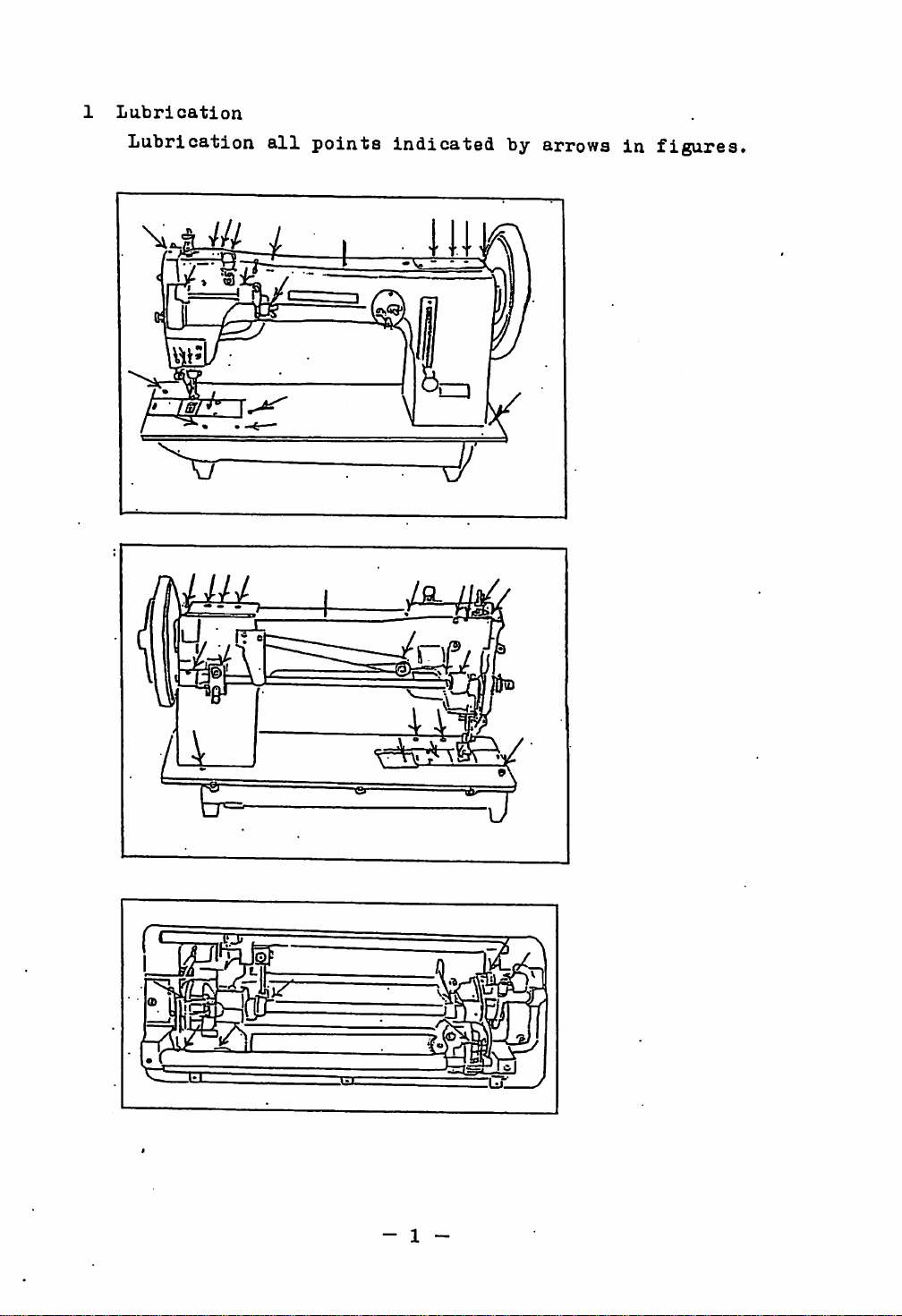
1
Lubrication
Lubrication
all
points
indicated
by
arrows
in
figures.
- 1 -
Page 5
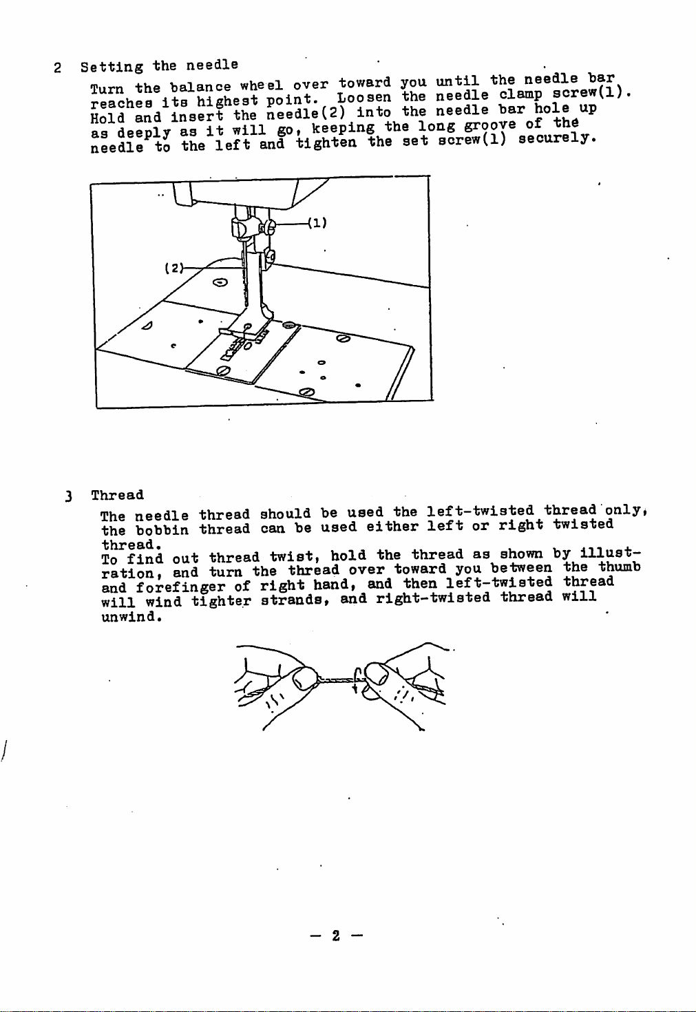
Setting
Tii-rn
Sold
as
deeply
needle
the
needle
+hP
balance wheel over tov/ard you
ita
Ind
to
hisLst
insert
as
it
the
left
Mint.
the
Ledle(2)
will
and
go,
tighten
Loosen
keeping
into
the
the
the
the
long
set
until
the needle
needle
needle
groove
sorew(l)
clamp
bar
hoi®
of the
securely.
"bar
sorew(l).
"P
3
Thread
The
the
To
find
ration,
and
will
unwind.
needle
bobbin
forefinger
wind
thread
thread
out
thread
and turn the thread over toward
tighter
should be
can be
twist,
of
right
strands,
used
used
hold the
hand,
and
the
left—twisted
either
and
right-twisted
left
thread
then
left-twisted
or
right
as
you
shown
between the
thread
thread
twisted
by
illust
thread
will
only»
thumb
- 2 -
Page 6
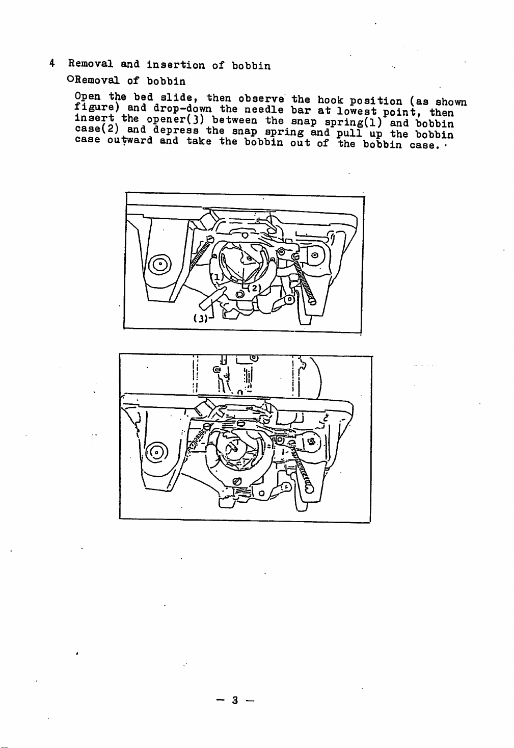
4
Removal
ORemoval
Open
the
figure)
caseu)
case
outward and
and
of
and
and
insertion
bobbin
bed
slide,
drop-do^
depress
of
bobbin
then observe the
the needle
the
take
the
snap
bobbin
bar
spring
out
hook
at
and
position (as
lowest
apring(l)
pull
up
of the bobbin
point,
and
the
case.
shown
then
bobbin
bobbin
•
b
- 3 -
Page 7

OInsertion
Put
down
bobbin
slit(7).
the
the
of
bobbin
bobbin(4)
thread
case
spring!6;
and
into
pass
to
the
bobbin
the
lead
thread
it
easel5)
through
out
from
while
underneath
the
bobbin
holding
the
case
5 Winding
the
bobbin
thread
Pass the thread in the order numerically
in
figures.
(1)
Spool
teneion thread guide
tension discs
guide—?-(5)
(6)
Move
pin—^(2)
»-(4)
Bobbin
the
bobbin winding
Thread
»-the
Meedle
guide
clearance between
thread tension
(winding several timesj ^
lever#
un-\U
instructed
(am)-^(3)
Needle
two
thr^d
Winding
left
length
&
rightward
shouldbeadjusted^by
the
positioning of the lever(6).
- 4 -
screw(7)
and
Page 8

6
Needle
threading
Pass
in
(3) Clearance between two
the
the
Spool
thread
figures.
pin—^(2)
in
the
Thread
order
tension
numerically
guide
of
discs
guide of thread tension ^(5) Thread
-I
®
^7^
Tension
Tension
(9) Thread guide on
(11)
Needle
single
sprffig_~^'(g)
spring
turn
^(q)
face
el
>-(6) Thread guide
Thread
plate
take
-^(10)
instructed
thread
tension
^(4)
controller
up
levIT^^
Needle clamp
Thread
discs
5^
Tension of bobbin
(A)
When
stitch tension is
IS enpged with the needle thread
material
(B)
Pig.
(B)
loose
thread
thickness,
shows
bobbin
and
as
unbalanced
thread.
- 5 _
needle
well
shown
(B)
thread
Balanced
balanced,
by
Tight
bobbin
tension, tight
(C)
Loose
bobbin
tension
at
fig.
the center of
(A)
needle
thread
needle or
thread
the
bobbin
of
loose
tension
needle
tension
thread
given
thread or
tight
Page 9

Adjusting
By
turning
nut
clockwiseneedle
tension
By
turning
nut
counter-clockwise^^^
thread
needle
increases.
tension
thread
the
tension
the
tensionregulating
decreases.
tension
regulating
thread
needle
S
Adjusting
By
loosening
screw(1).
The
set
the
bobbin
By
turning the tension
thread
regulating
decreases.
hoBbin
screw(l)
thread
tension
screw
set
thread
screw(l)
should
tension
tension
regulating
increases
counter—clockwise
and
exactly
was
and
tension
be
adjusted.
by
turning
regulating
tightened
screw
thread
after
clockwise/^
the
tension
tension
- 6 -
Page 10

8
Pressure
Loosen
of
the
clockwise^^pressre
thumb screw
^ter
in
adjustment,
accordance
presser
nut,
counter-clockwise^^>.pressure
with
lU
(ill
foot
then
tighten
the
turn
the
increases
the
materials
pressure
turn the pressure
nut.
Adjustment
to
regulating
be
sewn.
decreases,
should
thumb
screw
regulating
be made
Adjustment
perfSLld!
deoreasea,
ias
determined
of
Md
stitch
length
regulating
lever(l),
lever{l),
reverse
stitch
forward
knurling nut(2) 4 (3) clockwise/'"^ feed
by
turning the knurling nut(2) & (3) oounte?-
}^:
increases.
®^
ikO/.- A
The
knurling
®^^®^
(Note)
When
of
desired
upward
the
loosened,
feed
& downward movemei
regulating
the
screw(4) should be
is
atitlh
nut(2)
stitch
feed
performed,
is
length
&
length
lever
adjusting
tightened,
;
10
Determination
forward
Equivalent
obtained
feed
ing
and
by
regulating
collar
of
positioning
backward
stitch
adjustment
B)
should be placed
amount
length
set
plate(A)-, and
for
stitch
at
forward
of t upward &
back-lever(feed
on
feed regulating
- 7 -
length
and
backward
downward
at
can be
position
regulat
set
of
plate
(A)
Page 11

11
Timingofthread
(a)
When
(b)
moving
thread
Adjustment
Pull-up
clearance
of
disc(5)
releasing
the
should
tension
the
and
tension
the
be
—
presser
should
tighten
plate.
releasing
meohanism
lifting lever(l),
adjusted
"bar
be made
releasing
the
so
as
lifter(3),
over
plate(4)
screws(2)
to
3mm
upper
Sdo.
the
between
and
tension
on
the
tip
tension
ii
Page 12

12 Removal
Pull-down the opening &
lever(A) instructed in
tnd
then
and
remove
(B)
at
feed dog
Pig-3
shuttle
pull-down
-t—the
the
raised
instructed
shows
hook
removal
closing
the
fig-li
It
rlghtward
outer
position
in
hook
oi
the
of the shuttle
ring
Setting the shuttle
made
the
in
above
13 Adjusting
(A)Adjusting
Ledle^hoildhepositioned
feed
the
contrary
description.
hook
order
can
he
of
ri
rig-
2
on
the each points , *
dog
needle
and
position
moved
against
needle
together , the
Fig-
x.
holeoffeed
1
f7-B
dog.(
amount
out) of feed shaft
screw(3)
(Needle
is
to
of
needle
dog.)
be
•
dorpping
set
at
hole
point
the
of
("PP®r\acrew(3)
center
the
feed
- 9 -
(Note)
Peed
should
without
connector(A)(4).
shaf
t(upper)
be
moving
fixed
^ .
connector(
by the
feed
shaft(upper)
and
needle
..
AU4;
screw(3)
.
Page 13

(B)
Adjusting
the
height
of
feed
dog
(C)Adjuatment
I —
for
L^LIS
timingoffeed
and
position.
lipper&lowerf^d
aorews(l)
sh^t
ah^t
aMit(2)
8hlft?pf
„\^®
feed^do/shouid
at
the
dog-rise
vihfating
AdjustSenI
showf"^
o ^
oonneotor
la
"PP®''^lower
eod
-®^ace
PLUS^lwus+nK
of'^e^'e'^
set
adjusted
downwird!
materialstoSe
'r
foot
hf'
««
^®®'^
''®
116-5^(85"'
lower
screw
at
®^J*i3ted
fe,^.
'^og
®«°a
"^wo
Ot
a
^^^hoiltiin®
position
of
ri'T^s
16—17m*
0
Adjustment of the clearance between
presser
made
by
L.
forward
needle
»•
bar
and
the
acrew(l).
ZISlr
bar
needle
and
backward
frame
bar
rHis
is
to
be
e:?c:
O
imlQ
2
-10-
Page 14

(E)Timing
®
Positioning
When
from
hook
of
needle
the
its
should
of
needle
lowest
meet
and
needle
bar
positioni
the
hook
and
has
center
the
risen
the
tip
of
hook
4.5nutt - 5.5mm
tip
of
the
line
of
the
needle
Distance
and
the
©Adjusting
Loosen
between
tip
the
by wrench which
4^
V *4-
of
the
height
screw
the
the
inserts
2.3niiii'—3iaa
4.5iDni'-~5>
hook
of
adjust the needle bar{3) ^
©Adjusting
Loosen
spanner,
backward
of
hook.
adjustment.
the
the
then
(high
Tighten
position
screw(4)
determine
or
low
the
upper
should
of
needle
needle
to
of
of
the
the
speed)
screw(4)
5iiun
side
bar
the
upward
the
shaft
forward
of
the
be 2.5mm —
bar
connecting
hole(l)
and
tip
of
hook
crank
the
or
tip
of
after
needle-eye
3mm.
3tud(2)
of
arm and
downward.
by
£
m n
-
11
-
Page 15

©Adjusting the .clearance.between
needle
and
the tip of
hook
Loosen
rock
should
ward
set
frame,
be
or
leftward.
screw(l)for
then
mo-ved"4—^
Ij
needle
Pig--
©determination
lieedle
fdt
(4) positioned lower part of needle bar rock frame(2),
bar
ooai
rock
of
the
frame
position
for
7B & 8B
the
fi
of
needle
needle
bar
bar
rock
rock
frame
frame
outer
(Fig.
aP
/ - tip
—
tip
—0.05—0.3mn
hinge
hinge
hook
hook
right-
6)
hook
of
hook
stud,
stud(small)
and
also the
of
of
of
thT
feed
2^
® ^
dog
needle
°
moving
the balance
position,
bar rock
the
needle
needle
wheel,
r
Inn^
rock
wh«i f ^ frame(2),
wheel and
stitoh^skipplng
^
frame
tighten
looseness
hin^
position
needle
stud(small)(4) to slightly
bracket(8).
bar
rook frame hinge
the
of
each
the
screw
leftward
exactly.
&
rightward
resulted
frame
^Se
and
tighten
and
in
the
hinge
bar
determines
center
stud(large)
then
stud(large) (6).
stud(large)(6)
rock
frame
smooth
of
the
needle
the
set
screw(l)of
-fclie
needle
the
needle
bar bar
(6)
turn the balance
^ of the needle
leftward
to
breakingofneedle,
@
to
&
position
hole
bar
the
aide
12
-
Page 16

@Eaoh
a
timiag
Timingofinside
before
of
needle—eye
nrlsaei-
AdjS^ln?
for
up/down
bar
lifter,
irmade
moving
preeser
reaches
by
turning
two
amountofpresaer
to
feed
set
torews(2)ofupward&downward
the
dogi
after
balance
foot
Snwnina
downing
wheel
toward
(2B&8B
the^lever°®
only)
you.
By^up"!
needle
As
for
set
to
b For the
foot e(iuivalently, the
pinch
Ajustment should be
c
Up/down
presser foot
Upthe
Down
doTO^lifting
is
touch with feed dog
2B
Type,
at
same
setting
acrew(3)
moving
3crew(4)i
the
adjusting feed
point
of
io
amount
can
screw(4)
eooentriot-1'inside
either
dog
on
the upper face of the needle
inside
"to
made
be
obtained
the
,
be
presser
lifting
adjusted.
by the
of inside presser foot
amount
the
amount
eccentric connection crank
materials
by
loosing the screwt4;.
increases.
decreases.
J
Presser
speedily or slowly.
and
outer presser foot
foot
and outside
being
foot
and
against
plate.
presser
sewn.
outside
— 1 3 —
Page 17

1.
POSITION
Turn
its
the
( or
And
*
top dead
groove
-l^urn
on the
at
its
tighten
Needle
its
OF
the
h^Andwheel
the
cam
highest
lowers
highest
CAM(i^^28102)
until
center.
on
the
cam
cam,
and the
/'/28102,
center
point
the
screw(a)
//28102
by
0.4
point
FOR
the needle
At
this
faces
to
shown
securely.
mm
from
CONNECTING
bar
point,
the
make
of
the upper
as
the
center
upper
shaft
top.
set
i^mm
following
of
* Needle
ROD
lowers by
the
distance
shaft
I
Groove.
O.ifmm
cam(;^f28l02)
between
when
figure.)
the
1
1^
at
the
highest
from
with
the
groove
needle
• 1
i
is
1\
point
2.
POSITION OF FEEDING CAM(//28063)
STANDARD:
HOW
TO
(7B
Turn
screw
hole
(6B,
Turn
screw
groove
When
up
Imin
should
ADJUST:
and
8B
the
feed
in
rotating
A on
2B
and
the feed
in
rotating
on
swaying
and
down
this
type)
side
be
still.
cam(/ff28063)
direction
the
cara(#28102) and
2/RF
type)
cam(J/28063)
direction
the
cam
and
the
at
stitch
the
of
the
until
until
tighten
point
needle,
aligns
aligns
length
where
the
with
tighten
the lower
with
the
screw(B).
regulating
the
the
lower
the
the
the
point
feed
edge
dog
of
upper
screw(B).
edge
7p,oB
of the second
upper
(Fig.
lever(//28l6i|)
of
hook
and
the
edge
(Fig.
edge
4 )
^^ype
reaches
the
needle
second
of
the
3 )
of
the
center
qhaf
of
uppei
t
F;,.
3
Page 18

3.
HEIGHT OF
STANDARD;When
To
make
NEE;DLE
the
from
the
needle
surface
edge of the needle eye
f
30
pk'fe I
sure;
The
part
at
S
upper edge of the needle eye should
A of the needle guard
the
needle
is
of
is
its
the
its
highest
needle
is
30•
lowest
e
point,
plate
5^0.5>nra,
on
the
point.
the
to
height
the
shuttle
lower
reach
driver)
.
POSITION OF
Turn
extreme
the
hook with B
should
be
SHUTTLE
handwheel
left
side.
part
at
1mm
of
from
HOOK
until
At
the
the
this
driver,
the
shuttle
point,
edge
driver(#28/h51)
when
the
point
of
the
For adjustment, loosen the screw(^2810it
for
Flat
bed
type)
, , x
contacting
of the
shuttle
for
Cylinder type,
reaches
C
shuttle
race(E).
part
at
of
the
hooktD)
#28805
PL/IT
TTft-
_paPtf^
.
Page 19

;7^
"t
4-
V
6B.
Zb.CH^RF
i • Ji
w—^
 Loading...