

Page 1
TE
TF-B.BB
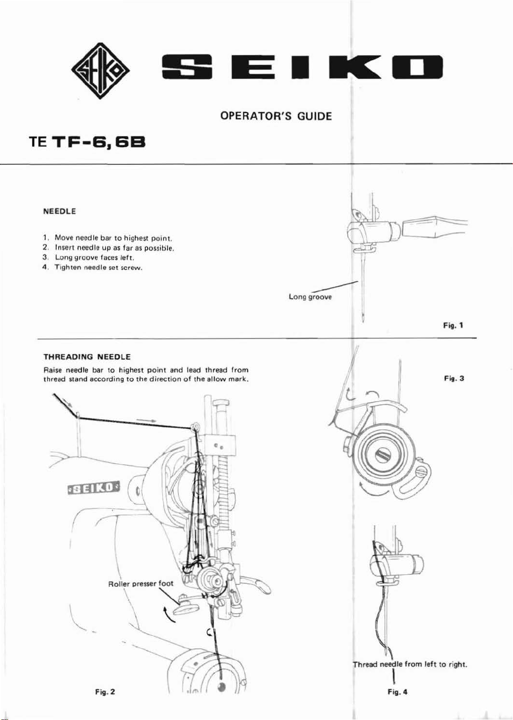
NEEDLE
OPERATOR
'S GUIDE
1. Move needle bar to highest poi
2. Insert needle
3. Long groove faces
4. Tighten needle set screw.
THREADING
Raise needle bar
thread stand according
up
as
left
NEEDLE
to
highest
far
to
as
possitile.
.
the
point
direction
~
:----
.....:
-=--
nt.
and lead thread
of
the
allow
from
mark
Long g
roov
e
----
Fig. 1
.
Fig. 3
Thread needle
F
ig.
2
\
\
Fig. 4
from
left
to right
.
Page 2
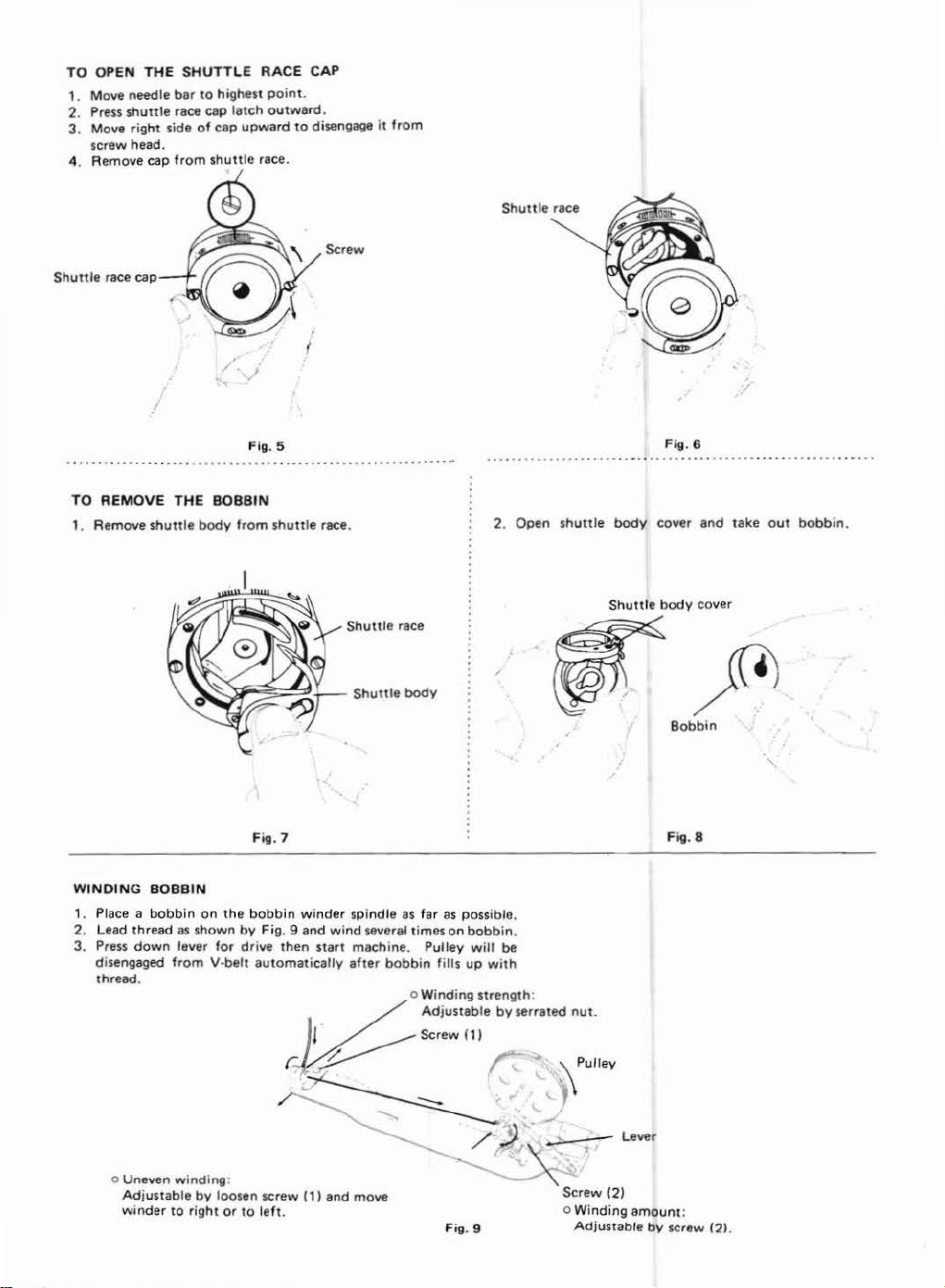
TO OPEN
1.
Move
2.
Press
3.
Move
screw head.
4.
Remo
Shuttle
THE
needle
shuttle
right
ve
cap
race cap
SHUTT
bar
to
race cap
side
of
from
LE
RACE
highest point.
latch
outward.
cap
upward
shuttle
race.
/
CAP
to
disengage it
Screw
from
TO
REMOVE
1. Remove
WINDING
1. Place a
2. Lead thread
3.
shuttle
BOBBIN
bobbin
Press
down
disengaged
thread.
THE
BOBBIN
body
on
the
as
shown
lever
for
from V·belt
Fig. 5
from
shutt
le race.
Shuttle
Fi
g.
7
bobbin winder spind le
by
Fig. 9
and
then
wind
start
mach
after
drive
automatically
race
as far
several times
ine.
Pulley
bobb
in f
as
possible.
on
bobbin
will
ills up
2. Open
.
be
with
Fig. 6
shuttle body
~~
Shuttle
cover
body
Bobbin
and
cover
take
out
bobbin.
'
Fig. 8
~Lever
Un
o
Ad
winder
even windi
justable
ng:
by
loosen screw (1)
to
right
or
to
left
Screw
and
.
move
Fig. 9
o Win
ding
Adjustable
(2)
amount
by
screw
:
121
.
Page 3

THREADING
1.
Hold
shuttle
shown
and
3.
Close
shuttle
THE SHUTTLE
in l
eft
bobb
cover
hand
in
place
body
(~
with
into
.
the
it.
open
side
Fig.
up
as
10
2.
Pass
THREAD
thread
TENSION
into
slot
as
shown
.
Fig.
11
BOBBIN
To
ADJUSTING
1.
2.
adjust,
To
shorten
feed
regulator
To
lengthen
Thumb
THREAD
turn
.. ,
adjusting
\ I
STITCH
the
sti t
downward
the
stitch, move feed
scre_w
Tension spring
screw
;(S$
·-
~.Q{J
\.~
LENGTH (Tf -6)
ch,
loosen
thumb
.
Tension
screw
screw and
regulator
Fig.
regulating
14
Fig.
move
upward
Fig.
16
12
.
~
~
~
NEEDLE
To
(TF·
6B)
Loosen
between
stitch
length
setting
Serrated
Fig.
13
THREAD
adjust,
turn
the
serrated
F and 0
in
setting
to 0 positiflo.
c . . t
nut
Lever
Perfect
Tight
Loo
se
serrated
nut
marks o n the
nut
and
adjust
to F position
<:1
....
----0
~
stitching
tension of needle thread
tension
of
needle thread
Serrated
stitch
plate. To
F
P
late
and
nut
length
increase
to
decrease
Fig.
by
Fig.
15
lever
the
17
in
REVERSE STITCHIN
(
only
Tf ·6B)
Press
down lever
Lever
/
as
far
T
G
as
ot will
..
go.
-----0
1
Fig. 18
TO
REGULATE
The
pressure
hile still
w
on
the met
sufficie.nt
PRESSER
More
~
erial
to
insure
FOOT
~
}
should
correct
PRESSURE
Less
be
as
light
feeding.
Fig.
as
possible,
19
Page 4

LUBRI
CATION
Use
white
sufficiently
-
...
~
-
t
,
...
r/
~
~-
·-
F
ig.
INSTALLATI
1.
Set
up
machine
2.
Attach
under
3. Install
bobbin
spindle oil. When
to
respective necessary
I
\
........
\ L
/•
20
ON OF THE
the
table
clut
table.
machine
and
ch
etc.,
moto
head
to
head.
the
the
the
winder,
starting
parts
.J
1-
MAC
HIN
stand before
r, knee lifter,
and
table
fix
.
the
the
before
E
the
the
machine
starting
I t
\
'~
'
'
·.
~-
.. ' •7-'\..
Fig. 21
installment
switch,
thread
initially
operation
~
~-
"'
~
y
-.
.
.~
• ·
#v·
~
~,,
'~
~
.
~;
~
of
etc.,
to
stand,
and
.
-
after
kept
and
pre-running. (l
2
away
for
a lo ng
....
/
Fig.
oiling
.. :
22
time
without
point)
-lb-
using
at
Fig.
all, oil
23
Fig.
24
1
0
.
'"
...
y
0
0
3
V-belt
Thread
stand
t 1 .
·'·
·--
h
l }
Fgi.
25
SEIKO
11
-3, lma
Tel
: (03)
Cabl
e Address:
SEWING
do
1-<:home,
872·6171-7,
"SEIKOSEWMCO"
MACHINE CO.,LTD
Telto-ku,
7288
Tokvo.
Telex: 26571
TOKYO
48
1 1 1
SEIKO
-\
Pedal
Jepen
Fig.
26
.
.
J
 Loading...