

Seiko S651A Service Manual
SERVICE GUIDE CAL. S651A
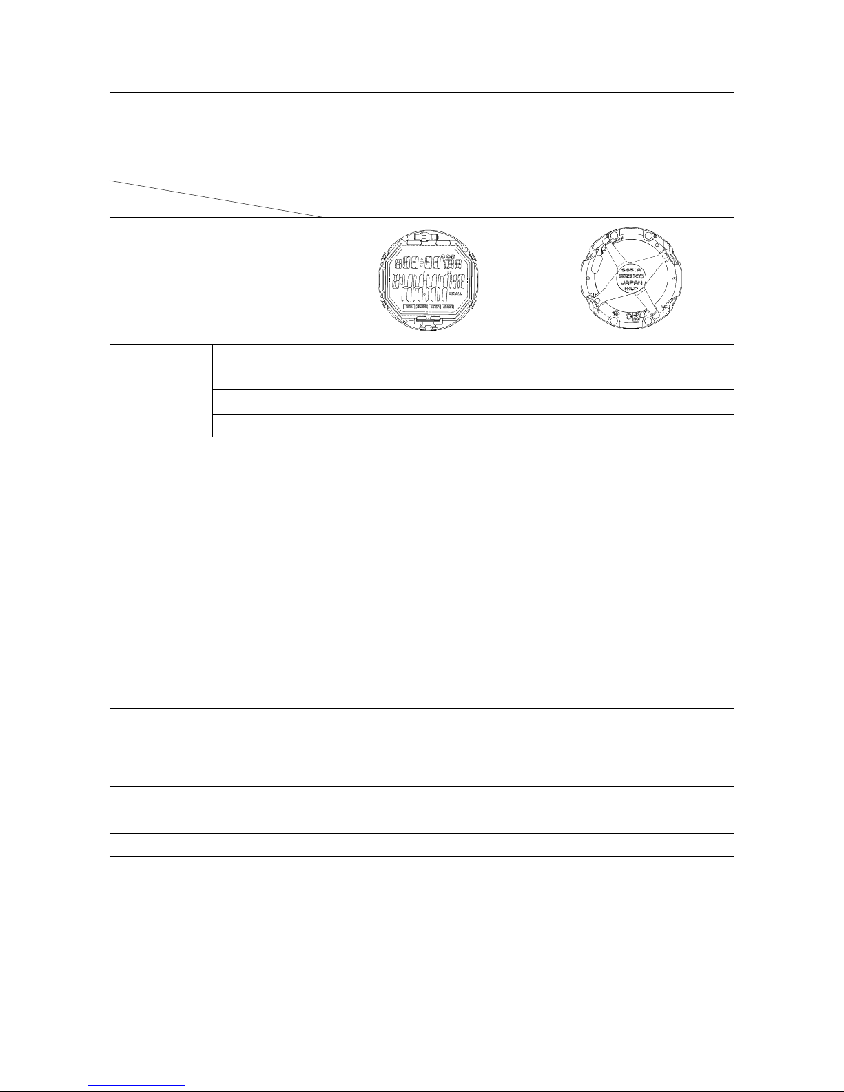
1. SPECIFICATIONS
S651A
Movement
Item
Cal. No.
(x 1.0)
ø27.9 mm
27.5 mm between 3 o’clock and 9 o’clock sides
27.7 mm between 6 o’clock and 12 o’clock sides
Movement size
Outside diameter
—
Casing diameter
Height
5.9 mm (6.0 mm including the battery portion)
Nematic Liquid Crystal, FEM (Field Effect Mode)
Display medium
Multiplex driving systemDriving system
Calendar display
• Month, date and day; full auto calendar (from January 1995 to
December 2044)
Time display
• Hours, minutes and seconds
Stopwatch display (Up to 10 hours in 1/100 second increments)
Memory recall display
• Lap time memory (Up to 8 lap times)
Timer display (Countdown timer in one second decrements)
• Adjustable timer (Up to 9 hours 59 minutes in one minute
increments)
• Preset timer (Selection of the preset time: 3, 5, 10 and 15 minutes)
Alarm display
• Daily alarm
Display system
Additional mechanism Electroluminescent panel
Confirmation sound for button operation
Battery life indicator
Sound demonstration
Auto illumination and auto signal function
Loss/gain Monthly rate at normal temperature range: less than 20 seconds
Regulation system Nil
Measuring gate by quartz tester Any gate can be used.
Battery
SEIKO CR2025, Sony CR2025, Matsushita CR2025, Maxell CR2025,
Eveready ECR2025
Battery life is approximately 2 years.
Voltage : 3.0 V
2. VALUE CHECKING
• Current consumption: less than 5.5 µA
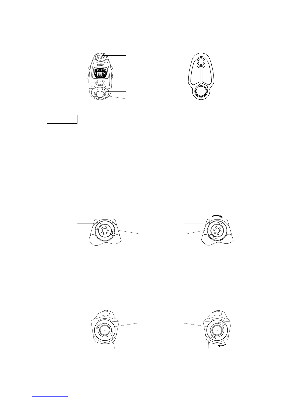
● PARTS OF THE AIR CHAMBER UNIT
● Before removing the air chamber from the watch case or attaching it to the case for such purposes as cleaning
and replacement with a new one, be sure to let the air completely out of it.
● When attaching the air chamber to the watch case, be sure to set the protruding portions of both the rings
at the 6 and the 12 o’clock sides to the small protrusions on the case to fix the air chamber. Otherwise, the
air chamber may come off of the case.
1. HOW TO REMOVE / ATTACH THE RING AT THE 12 O’CLOCK SIDE
● How to remove
Turn the ring in the direction of the arrow to set
its protruding portion to the small hole on the
case, and then, remove the ring.
● How to attach
To fix the ring, set the protruding portion of the
ring to the small hole on the case, and turn the
ring in the opposite direction to the arrow until
the ring’s protruding portion aligns with the
small protrusion on the case.
Remarks
For the parts code, refer to the Casing Parts Catalogue of each model.
Ring
Air pump
Ring (Air release button)
Air chamber
Small hole
on the case
Ring at the 12 o’clock side
Small protrusion
on the case
Ring’s protruding portion
2. HOW TO REMOVE / ATTACH THE RING AT THE 6 O’CLOCK SIDE
● How to remove
Turn the ring in the direction of the arrow to set
its protruding portion to the small hole on the
case, and then, remove the ring.
● How to attach
Set the protruding portion of the ring to the small
hole on the case, and turn the ring in the opposite
direction to the arrow until the ring’s protruding
portion aligns with the small protrusion of the
case. The ring will fix into place with a click.
Ring at the 6 o’clock side
Ring’s protruding portion
Small hole on the case Small protrusion on the case
 Loading...