

Seiko S140A, S143A Parts Catalogue /technical Manual
1
PARTS CATALOGUE / TECHNICAL GUIDE
Cal. S140A, S143A
Cal. No.
Item
S140A
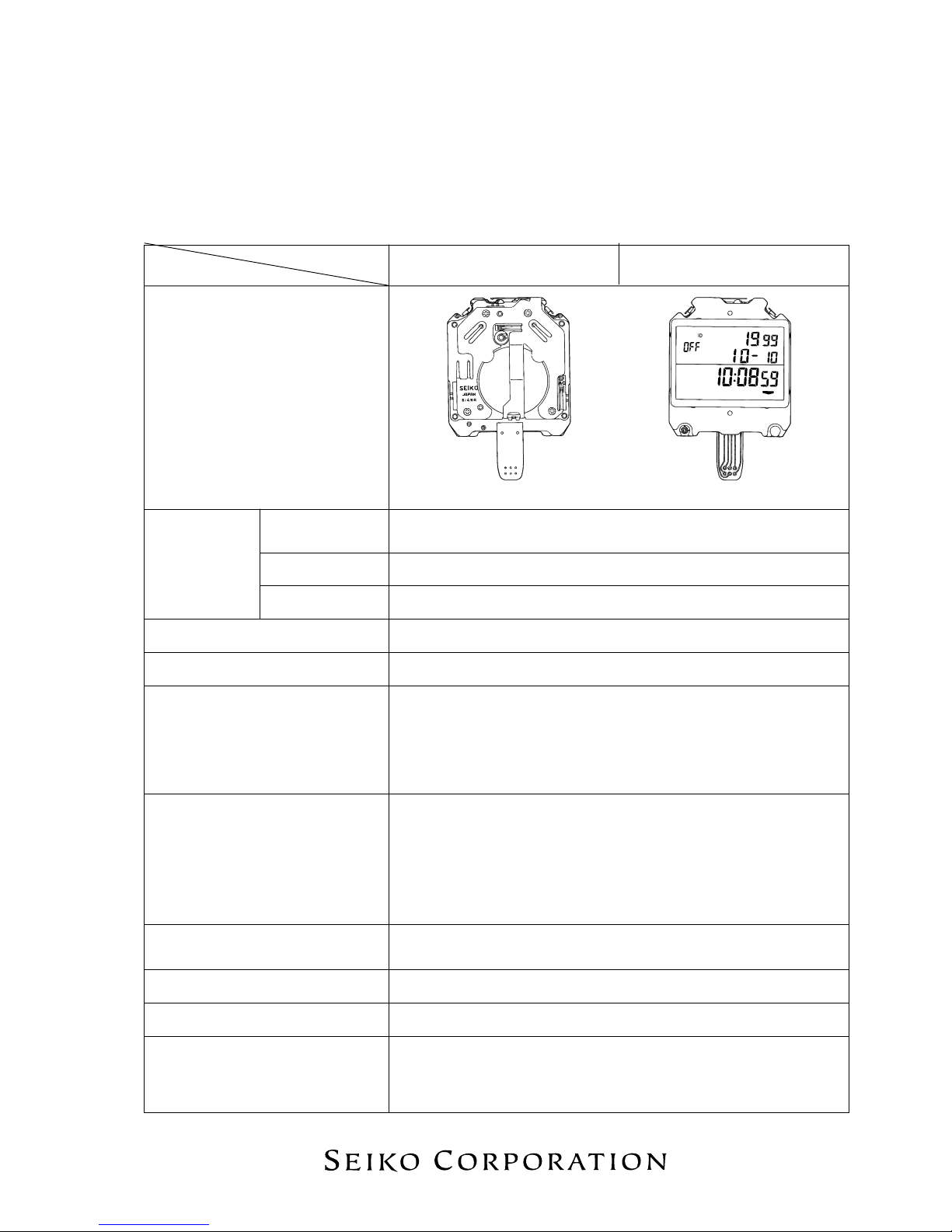
(x 0.7)The illustrations refer to Cal. S143A.
Module
Module size
Outside diameter 49.3 mm between 6 o’clock and 12 o’clock sides
43.0 mm between 3 o’clock and 9 o’clock sides
[SPECIFICATIONS]
S143A
–Casing diameter
Height 8.75 mm
Display medium Nematic Liquid Crystal, FEM (Field Effect Mode)
Liquid crystal driving system
1/4 multiplex driving system
Display system • Stopwatch display (Up to 10 hours)
• Split time/lap time measurement
• Total time measurement/lap time measurement in progress
• Time/calendar display
• Stroke display (Only for Cal. S140A)
Additional mechanism • Memory function: Up to 300 measurements
• Memory capacity indicator
• Confirmation sound for watch operation
• Contrast adjustment function
• Battery life indicator
• Printout function (Only for Cal. S143A)
Regulation system
Nil
Measuring gate by quartz tester Any gate can be used.
Battery SEIKO CR2430, Sony CR2430
Battery life is approximately 3 years.
(When the stopwatch is used for 3 hours a day or less)
Voltage: 3.0 V
±0.0006% at normal temperature range (corresponds to a loss/gain
(monthly rate) of less than 15 seconds)
Loss/gain
2
PARTS CATALOGUE
Cal. S140A, S143A
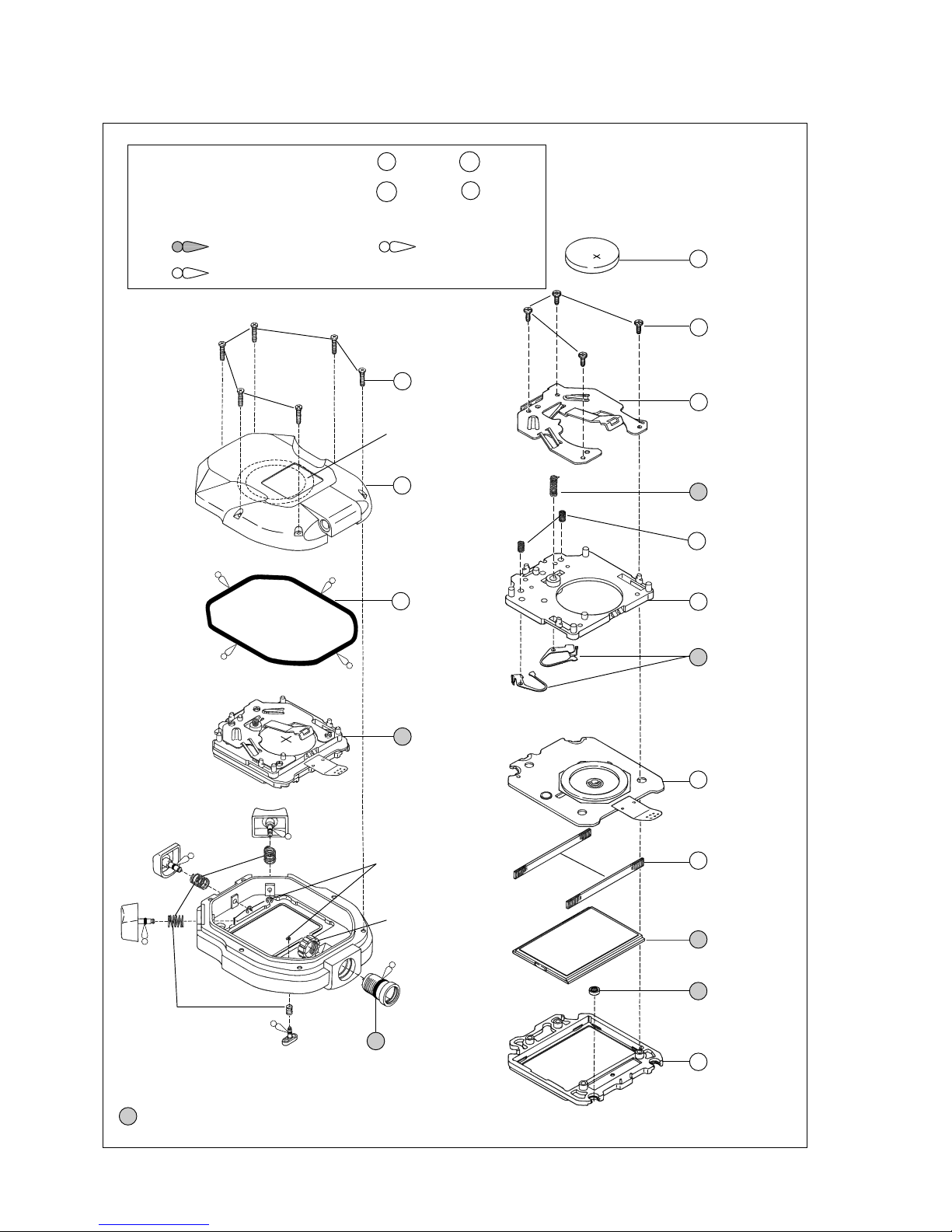
Disassembling procedures Figs. : 1 → 17
Reassembling procedures Figs. : 17 → 1
Lubricating: Types of oil Oil quantity
SEIKO Watch Oil S-6 Normal quantity
Silicone oil 500,000
➡
Please see the remarks on the following pages.
(Lubricating of some parts is shown in “III. REMARKS ON DISASSEMBLING AND REASSEMBLING”)
1 Case back screw
2 Case back
Piezoelectric element
3 Case back
gasket
4 Module
5 7504 620
Jack
(only for Cal. S143A)
Jack nut
(only for Cal. S143A)
Button B
Button C
Button A
Button D
Button spring clip
Button spring
7 0022 922
Circuit block
cover screw
6 Battery
(See the
front page.)
8 4457 753
(for Cal. S140A)
4457 754
(for Cal. S143A)
Circuit block
cover
9 4246 825
Buzzer lead
terminal
10 0353 503
Spring for
switch
conductivity
11 4410 779
Circuit block
case
12 4450 851
Switch lever
13 4000 875
(for Cal. S140A)
4000 872
(for Cal. S143A)
Circuit block
14 4313 825
Connector
15 Liquid crystal
panel
16 4313 826
Switch connector
17 4512 850
Liquid crystal
panel frame
3
Remarks:
PARTS CATALOGUE
Cal. S140A, S143A
TECHNICAL GUIDE
• The explanation here is only for the particular points of Cal. S140A and S143A.
• For the repairing, checking and measuring procedures, refer to the “TECHNICAL GUIDE, GENERAL
INSTRUCTIONS”.
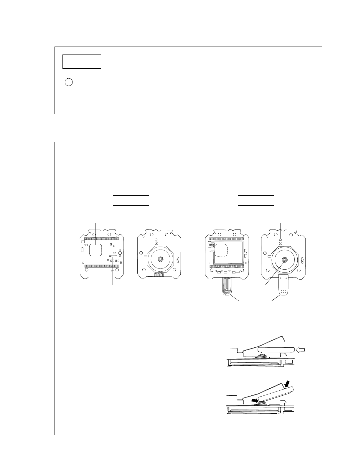
I. STRUCTURE OF THE CIRCUIT BLOCK
II. REMARKS ON BATTERY REPLACEMENT
Cal. S140A, S143A
15 Liquid crystal panel 4520 504
The type of liquid crystal panel is determined based on the design of cases. Check the case number and
refer to “SEIKO Casing Parts Catalogue” to choose a corresponding liquid crystal panel.
Cal. S140A Cal. S143A
C-MOS-LSI Input terminal (+)
Input terminal (–)Crystal unit
C-MOS-LSI Input terminal (+)
Input terminal (–)
Jack lead terminal
• Remarks on installing the battery
· Keep the battery level while installing it lest it should
touch the circuit block cover.
· Be careful not to short-circuit the battery connection (–)
and the circuit block cover. In that case, the display may
remain blank after the battery is installed.
* If the display remains blank, wait until the battery voltage
returns to the normal level. The normal display will
return.
Example of short circuit
4
TECHNICAL GUIDE
Cal. S140A, S143A
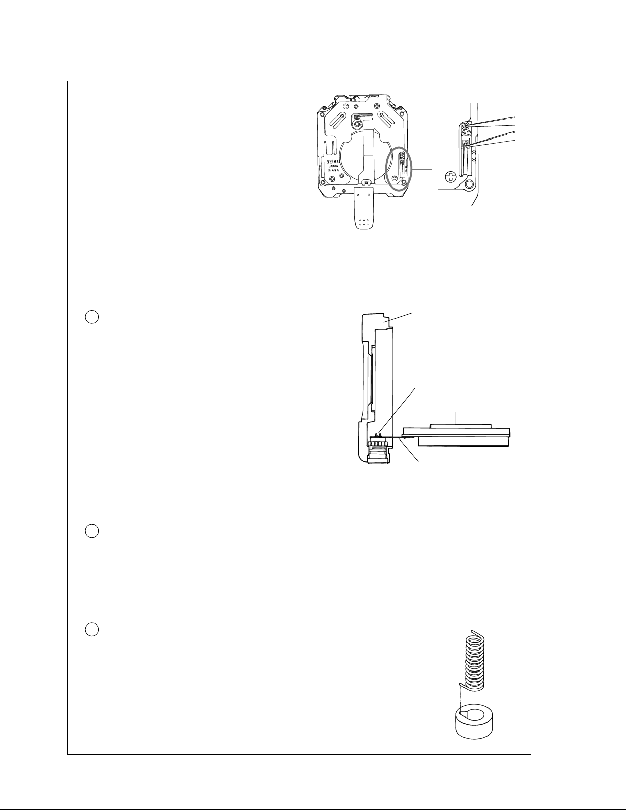
• Remarks after installing the battery
After the battery is replaced with a new one, or after
the battery is re-installed following the repairing
procedures, be sure to short-circuit the AC terminal
of the circuit block and the circuit block cover with
conductive tweezers for more than 2 seconds as
illustrated at right to reset the circuit.
▼
III. REMARKS ON DISASSEMBLING AND REASSEMBLING
Use the universal movement holder for disassembling and reassembling.
4 Module (Only for Cal. S143A)
• How to remove
Unsolder them with a soldering iron, soak up the
melted solder completely with a solder wick or the
like, and then, remove the jack lead terminal.
• How to install
Set the jack lead terminal to the jack pin, taking care
not to set it upside down. Then, re-solder them with
the soldering iron.
The jack and the jack lead terminal are soldered together.
Note: When using the soldering iron, take utmost care not to deform or damage the case and other
parts by the heat of the soldering iron.
Case
Liquid crystal panel
Jack lead terminal
Soldered portion
5 Jack
The jack is only available for supply with the nut.
• How to install
To reassemble the jack, set the notch of the jack to the groove of the case.
9 Buzzer lead terminal
• How to remove
Remove the buzzer lead terminal after detaching the circuit block case from
the circuit block.
• How to install
To install the buzzer lead terminal, set the end portion of the buzzer lead
terminal to the groove of the circuit block case, and then, turn the buzzer lead
terminal slightly so that it does not come off.
 Loading...