

Page 1

USER'S GUIDE
Thermal Printer
MP-A40 SERIES
Read this USER'S GUIDE carefully before using the printer.
Keep this USER'S GUIDE in a place where it can be accessed
quickly.
Page 2

MP-A40 SERIES THERMAL PRINTER USER'S GUIDE
U00137991300 August 2016
U00137991301 November 2016
U00137991302 January 2018
The information contained herein is the property of SII and shall not be reproduced in whole or in part without prior written
approval of SII.
SII reserves the right to make changes in the specifications and materials contained herein without notice and shall not be
responsible for any damages (including consequential) caused by reliance on the materials presented, including but not
limited to typographical, arithmetic, and listing errors.
Copyright 2016-2018 by Seiko Instruments Inc.
All rights reserved.
is a trademark of Seiko Instruments Inc.
Apple®, iPhone®, iPad®, iPod® are trademarks of Apple Inc.
Bluetooth® is a registered trademark of Bluetooth SIG, Inc.
IOS is a trademark or registered trademark of Cisco in the U.S.
and other countries and is used under license.
All other trademarks are the properties of their respective companies.
Applicable EC Directive and Standards
Product: Thermal Printer MP-A40-B
Directive: Title
2014/53/EU Radio Equipment Directive
2011/65/EU Restriction of the use of certain hazardous substances (RoHS) Directive
Standards
EN 301 489-1
EN 301 489-17
EN 300 328
EN 60950-1
EN 50581
Product: Thermal Printer MP-A40-W
Directive: Title
2014/53/EU Radio Equipment Directive
2011/65/EU Restriction of the use of certain hazardous substances (RoHS) Directive
Standards
EN 301 489-1
EN 301 489-17
EN 300 328
EN 301 893
EN 60950-1
EN 50581
Restrictions: Operations in 5150-5250 MHz band is for indoor use only.
This product may be used in following all EU and EFTA countries:
EU
Austria, Belgium, Bulgaria, Croatia, Cyprus, Czech Republic, Denmark, Estonia,
Finland, France, Germany, Greece, Hungary, Ireland, Italy, Latvia, Lithuania,
Luxembourg, Malta, Poland, Portugal, Romania, Slovakia, Slovenia,
Spain, Sweden, Netherlands, United Kingdom
EFTA
Iceland, Norway, Switzerland, Liechtenstein
Page 3

Product: AC adapter PW-D0940-W2
Directive: Title
2014/30/EU EC Electromagnetic Compatibility Directive
2014/35/EU EC Low Voltage Directive
2011/65/EU Restriction of the use of certain hazardous substances (RoHS) Directive
Standards
EN 55032 Class B
EN 61000-3-2
EN 61000-3-3
EN 55024
EN 60950-1
EN 50581
Product: Battery Charger PWC-A071-A1
Directive: Title
2014/30/EU EC Electromagnetic Compatibility Directive
2011/65/EU Restriction of the use of certain hazardous substances (RoHS) Directive
Standards
EN 55032 Class A
EN 61000-3-2
EN 61000-3-3
EN 55024
EN 50581
Federal Communications Commission (FCC) compliance statement
NOTE: This equipment has been tested and found to comply with the limits for a Class A digital device, pursuant to part 15
of the FCC Rules. These limits are designed to provide reasonable protection against harmful interference when the
equipment is operated in a commercial environment. This equipment generates uses and can radiate radio frequency
energy and, if not installed and used in accordance with the instruction manual, may cause harmful interference to radio
communications. Operation of this equipment in a residential area is likely to cause harmful interference in which case the
user will be required to correct the interference at his own expense.
The changes or modifications not expressly approved by the party responsible for compliance could void the user’s
authority to operate the device.
Operations in 5150-5250 MHz band is for indoor use only.
Industry Canada (IC) compliance statement
This device complies with Industry Canada’s licence-exempt RSSs. Operation is subject to the following two conditions:
(1) This device may not cause interference; and
(2) This device must accept any interference, including interference that may cause undesired operation of the device.
Operations in 5150-5250 MHz band is for indoor use only.
RF exposure compliance
This transmitter must not be co-located or operating in conjunction with any other antenna or transmitter.
Applied to only Bluetooth model:
contains FCC ID: QOQBT121
contains IC: 5123A-BGTBT121
Applied to only WLAN model:
contains FCC ID: C4ZAB000005
contains IC: 4445A-AB000005
Page 4

1. INTRODUCTION
This manual describes how to handle MP-A40 thermal printer (hereinafter referred to as printer), battery
pack, AC adapter, AC cable, car charger, and battery charger.
Read through "2. SAFETY PRECAUTIONS" and "3. OPERATING PRECAUTIONS" carefully before
using the products, and handle them safely and properly.
Keep this manual in a place where it can be accessed quickly.
See "MP-A40 SERIES THERMAL PRINTER TECHNICAL REFERENCE" for more detailed function and
specifications on the printer.
This USER'S GUIDE consists of the following sections.
1. INTRODUCTION ................................................................................................................................. 1
2. SAFETY PRECAUTIONS .................................................................................................................... 2
3. OPERATING PRECAUTIONS ............................................................................................................. 7
4. PREPARATION .................................................................................................................................. 11
5. IDENTIFYING THE MODEL TYPE .................................................................................................... 13
6. EACH PART OF PRINTER ................................................................................................................ 14
7. LED DISPLAY OF PRINTER ............................................................................................................. 16
8. POWER CONNECTION .................................................................................................................... 19
9. THERMAL PAPER SETTING ............................................................................................................ 23
10. TEST PRINT ...................................................................................................................................... 27
11. FUNCTION SETTINGS ..................................................................................................................... 33
12. CONNECTING TO THE HOST DEVICE ........................................................................................... 36
13. PAPER WIDTH SETTING .................................................................................................................. 40
14. INSTALLING BELT CLIP / SHOULDER STRAP ............................................................................... 44
15. CHARGING BATTERY PACK ............................................................................................................ 49
16. CHARGING BY CAR CHARGER ...................................................................................................... 53
17. CHARGING BY BATTERY CHARGER ............................................................................................. 58
18. PRINTER MAINTENANCE ................................................................................................................ 65
19. TROUBLESHOOTING ....................................................................................................................... 66
20. SPECIFICATIONS ............................................................................................................................. 67
21. ACCESSORIES AND CONSUMABLE PARTS ................................................................................. 71
22. MS SETTINGS LIST .......................................................................................................................... 72
1
Page 5

2. SAFETY PRECAUTIONS
In this SAFETY PRECAUTIONS, the following symbols are used to ensure safe and proper use of
products and prevent from damaging devices.
WARNING
CAUTION
About symbols
The symbol indicates information which you should pay attention to (including danger
and warnings).
The symbol indicates information about prohibited procedures.
indicates "Disassembly is prohibited."
The symbol indicates information about obligated or instructed procedures.
indicates "Unplug the power plug from an outlet."
Failure to follow the instructions marked with this symbol could
result in severe personal injury or death.
Failure to follow the instructions marked with this symbol could
result in minor personal injury or property damage.
2
Page 6

OPERATING PRECAUTIONS
The "products" shall collectively mean the printer, the battery pack, the AC adapter, the AC cable, the car
charger, and the battery charger.
WARNING
Never attempt the followings. Failure to follow the instructions leads to fire, electric shock, or accident.
DO NOT disassemble or reconstruct the products.
Take care not to spill liquid on the products.
DO NOT touch the products with wet hands.
DO NOT insert any foreign objects such as a piece of metal or any liquid into the products.
Keep the terminals of the products, power connector, AC plug, DC plug, and cigar plug away from
dust and metal objects.
DO NOT touch the terminals of the products, power connector, AC plug, DC plug, and cigar plug.
To avoid short circuits, prevent terminals of the products, power connector, AC plug, DC plug, and
cigar plug from touching any conductor such as metal.
Make sure that the AC plug, DC plug, and cigar plug are securely plugged in when using the
products.
DO NOT damage the AC cable, AC plug, DC plug, and cigar plug.
DO NOT bend, pull, twist the cable forcibly or place heavy stuff on it.
Use the printer only with the specified battery pack, specified AC adapter, specified AC cable, and
specified car charger.
Use the AC adapter only for the specified printer or specified battery charger.
DO NOT connect any AC cable other than specified with the AC adapter.
Use the battery charger only with the specified battery pack, specified AC adapter, and specified
AC cable.
DO NOT connect the car charger to the battery charger.
DO NOT use the AC adapter and the car charger at a voltage other than the specified voltage.
DO NOT charge the battery pack by any printer or battery charger other than the specified printer
or specified battery charger.
Be sure to charge the battery pack under the specified temperature range. Otherwise, it may
cause leakage, overheating, rupture, or fire.
3
Page 7

DO NOT expose the battery pack in a fire or heat it.
DO NOT leave the battery pack under high temperature conditions such as in scorching heat,
inside a car, or near a fire. It may cause leakage, overheating, rupture, or fire.
DO NOT apply strong impact to the battery pack with a hammer or a nail, and DO NOT crush it.
DO NOT print out during a vehicle driving. Ejected thermal paper may hinder a vehicle driving.
Be sure to observe the following instructions. Failure to follow the instructions may lead to fire, electric
shock, or accident.
Be sure to use only in countries where the products meet the regulations.
Using non-compliant products may endanger the safety of products or be considered against
regulations.
Be sure to hold the plug when unplugging the AC cable, DC cable, or cigar plug from an outlet.
Make sure to turn off the printer before connecting the AC adapter. After plugging the DC plug of
AC adapter, plug the AC plug to an outlet.
Make sure to turn off the printer before connecting the car charger. After plugging the DC plug of
the car charger, plug the cigar plug to a car accessory socket.
Make sure to turn off the printer when installing/removing the battery pack.
Make sure to unplug the AC plug from an outlet after using the battery charger. And make sure to
remove the battery pack from the battery charger.
Make sure to unplug the cigar plug from a car accessory socket after using the car charger.
4
Page 8

Procedures to take when in trouble
Follow the instructions in the following cases. Failure to follow the instructions may lead to fire, electric
shock, or accident.
Turn off the printer, and unplug the AC plug from an outlet in any of the following cases. (In case
of using the car charger, unplug the cigar plug from a car accessory socket.) And then, remove
the battery pack.
Abnormal status continues.
◆
◆ The products are giving off an unusual smell, smoke, excessive heat or unusual noise.
◆ A piece of metal, water or other foreign objects get into the products.
◆ The case is broken.
When the cable of the AC adapter or AC cable is damaged, unplug the AC plug from an outlet.
DO NOT use a damaged AC adapter or AC cable.
When the cable of the car charger is damaged, unplug the cigar plug from a car accessory
socket. DO NOT use the car charger which has damaged cable.
In any of the following cases, remove the battery pack from the printer or battery charger. Then,
stop using the battery pack and never put it close to fire.
The battery pack is giving off an unusual smell, smoke or excessive heat.
◆
◆ The case is broken.
◆ Liquid is leaking.
When leaking liquid from battery pack gets into eyes, flush them immediately with clean water
and see a doctor immediately.
Otherwise it may cause vision loss.
For wireless communication
Observe the following instructions.
Always turn off the printer in areas or regions where its use is prohibited, such as on the airplane.
This function may adversely affect medical and electronic devices. Consult the manufacturer or
the dealer of the devices to determine when they are shielded adequately.
5
Page 9

Observe the following instructions. Failure to follow the instructions may lead fire, electric shock, or
accident.
Turn off the products and unplug the AC plug from an outlet when not in use for a long time or
before maintenance. And remove the battery pack from the printer or battery charger.
DO NOT use or store the products in the following locations:
Locations exposed to direct sunlight or high temperature such as in a car.
◆
◆ Locations exposed to high humidity, a lot of dust, and liquid.
◆ Locations subject to strong vibration or unstable locations.
DO NOT cover the products with a cloth when in use.
NEVER touch the thermal head immediately after printing because it may get hot. Be sure to allow
it to cool down before clearing a paper jam or cleaning its head.
The printer has 2 paper cutters on the paper outlet: one is on the printer side, and the other is on
the paper cover side. DO NOT touch the cutters directly with hands. Especially, make sure not to
touch the exposed cutters while the printer cover is open.
Keep loose objects such as long hair away from the printer while the printer operates. When they
fall into the printer, it may cause personal injury or damage the printer.
To prevent the battery pack from dropping off, be sure to install and fix the battery pack securely to
the printer or battery charger. Dropped battery pack may cause personal injury or malfunction.
When using the belt clip, be sure to install the battery pack in the printer because the belt clip
comes off too easily from the printer without installing the battery pack. Dropped printer may
cause personal injury or malfunction.
When using the shoulder strap, be sure to install the shoulder strap securely to the printer.
Dropped printer may cause personal injury or malfunction.
Avoid the direct skin contact with the battery pack while using the belt clip or shoulder strap.
Prolonged skin contact may cause low-temperature burns.
Keep the products away from infants and children.
When leaking liquid from battery pack contacts your skin or clothing, flush them immediately with
clean water.
6
Page 10

3. OPERATING PRECAUTIONS
Be careful of the following precautions and use the products properly in order to deliver and maintain the
full performance of the products.
Using the Products
Precautions for using conditions
◆ Be careful not to drop or bump the products on a hard surface.
◆ DO NOT install the products in direct sunlight.
◆ Be careful about the ambient temperature and humidity.
Suitable environment for the use of the printer is as follows:
Range of the temperature Range of the humidity
Print with battery pack -4°F to 122°F
(-20°C to 50°C)
Print with AC adapter 32°F to 104°F
(0°C to 40°C)
Charge battery pack 32°F to 104°F
(0°C to 40°C)
10%RH to 90%RH
(Non condensing)
20%RH to 80%RH
(Non condensing)
20%RH to 80%RH
(Non condensing)
See "MP-A40 SERIES THERMAL PRINTER TECHNICAL REFERENCE" for the certifiable humidity
range at each temperature.
◆ DO NOT install the products near devices that generate strong electromagnetic fields such as a
copy machine motor.
◆ DO NOT install the products in a location that is subject to corrosive gas, siloxane and so on.
◆ DO NOT connect the AC adapter or the AC cable to the same outlet with devices that generate
noise.
Precautions when using or driving
◆ DO NOT print without the thermal paper.
◆ DO NOT use thermal papers taped together.
◆ NEVER pull out the thermal paper when the thermal paper is set.
◆ DO NOT open the paper cover during printing.
◆ DO NOT touch the thermal paper during printing. Covering the paper outlet or pulling out the
thermal paper when ejecting may cause a paper jam or line feed failure.
◆ DO NOT connect or disconnect the interface cable during printing or transmission.
DO NOT touch the plug of the interface cable during printing.
◆ When handling the printer, be aware of static electricity. When the static electricity is discharged,
this could cause a USB communication failure.
When this problem occurs, disconnect the USB plug that is connected to the host device and wait a
few seconds before connecting it again.
◆ DO NOT remove the battery pack or AC adapter during printing or transmission.
7
Page 11

◆ Even if the printer connects with the AC adapter during printing or communication using the battery
pack as the power source, the power supply from the battery pack will continue until printing or
communication is completed.
If the printer suspends printing because the battery remaining capacity becomes low, connect the
AC adapter and resume printing or communication.
◆ DO NOT use the thermal head when it is wet. Doing so may damage the printer.
◆ Using the printer under low temperature environment or printing at a high print rate might cause
unclear printing or generate loud sound. This is not a failure in the printer but an inherent paper
phenomenon.
◆ Continuous printing with high print rate might cause temporarily stop printing by temperature
detection of the printer. Printing resumes when the printer's temperature cools down. When this
error occurs and "Data discarding when error occurs" in the Function Settings is "Enabled", the
transmitted print data while this error occurs is discarded.
◆ When the battery pack is used at low temperature, the operating time of the printer can be used may
be shortened.
◆ The indicator of battery remaining capacity displayed in the POWER LED is for reference. The
battery level may be changed depending on the printer operation, so charge the battery pack before
the battery becomes low.
◆ The battery pack should be charged at 32°F to 104°F (0°C to 40°C).
◆ The charging time depends on the ambient temperature and the voltage level of the battery pack.
Normally, using the printer or the battery charger "PWC-A071-A1", it takes about 4 hours to
complete charging after running down the battery pack.
Using the quad battery charger "PWC-A074-A1", it takes about 5 hours.
◆ The battery pack, AC adapter and car charger may get hot when in use. This is normal and not a
malfunction.
◆ After using the battery charger, unplug the AC plug from the outlet. And then, remove the battery
pack from the battery charger.
◆ Set the paper width before using the printer for the first time. DO NOT change the paper width after
starting to use the printer. Doing so may damage the printer.
◆ Always use the specified thermal paper. See "21. ACCESSORIES AND CONSUMABLE PARTS" for
details.
◆ DO NOT touch the thermal head directly. Doing so may result in poor printing quality due to the dirt
or damage by the static electricity.
◆ DO NOT touch the thermal head, paper sensor, or platen roller directly with hands while opening the
paper cover to install the thermal paper. Doing so may cause injury or other accidents.
◆ The printer has 2 paper cutters on the paper outlet: one is on the printer side, and the other is on the
paper cover side. DO NOT touch the cutters directly with hands. Especially, make sure not to touch
the exposed cutters while the printer cover is open.
◆ Be careful not to get your fingers or hands caught in the printer when opening or closing the paper
cover.
8
Page 12

◆ Cutting label sheets at the part other than release paper with the paper cutter, the label sheet
adhesive may stick to the cutter, and the cutting ability may deteriorate.
◆ The car charger is only for charging. Even if the car charger is connected to the printer, the printer
cannot print without the battery pack.
◆ Charging the battery pack by car charger is possible while the car engine is running or in accessory
position. Ensure that the car battery remaining capacity is sufficient before using the car charger in
accessory position.
◆ After using the car charger, be sure to unplug the cigar plug from a car accessory socket.
◆ DO NOT print out during a vehicle driving. Ejected thermal paper may hinder a vehicle driving.
◆ DO NOT drop or insert any foreign objects such as clips, pins, and screws in the internal parts or
slot of the products.
◆ DO NOT drop any liquid or spray a solvent to the products.
◆ NEVER use sharp object such as pen tip to push the switch on the operation panel.
◆ Make sure not to injure your body or other objects by the plate edge.
◆ When something goes wrong with the printer during use, stop using it immediately, unplug the AC
plug or cigar plug from the outlet or car accessory socket, and remove the battery pack.
◆ NEVER disassemble the printer without a serviceman.
Precautions for Wireless communication
◆ When using the Bluetooth interface, the communication may become unstable due to the influence
from any external radio waves. This is the specification of Bluetooth for wireless communication
standard.
◆ The Bluetooth model uses 2.4GHz frequency range. The Wireless LAN model IEEE802.11b/g/n
uses 2.4GHz frequency range, and IEEE802.11a/n uses 5GHz frequency range. So if these models
are used around any equipment with the same frequency range such as other wireless LAN
networks and microwave oven, radio frequency interference may occur, and the communication
may become unstable. When it happens, turn off the interfering equipment or increase the distance.
In addition, shorten the distance between the host device and the printer as much as possible.
◆ When using the Wireless LAN model IEEE 802.11a/n, the printer may stop communication
temporarily before outputting radio wave to the target channel not to affect the weather radar, air
traffic control radar or others. This is to monitor the presence of radar waves for a certain time. If the
printer detects radio waves such as radar during operation, it may switch to another channel.
Precautions for maintenance
◆ Clean the products’ cases using a soft and lint-free cloth. DO NOT use alcohol or other solvent.
◆ Before using, always clean the terminals using a dry, soft, and lint-free cloth. When the terminals are
dirty, it may cause contact failure.
◆ When cleaning the thermal head, wipe the thermal head with a cotton swab or other soft material.
9
Page 13

Precautions for storing
◆ Turn off the power when not in use.
In addition, when the printer is not used for a long time,
・Unplug the AC plug from an outlet.
・Remove the battery pack from the printer. If not, it may cause overdischarge, and the battery pack
is not available for use even if it is charged.
・Set thermal paper to protect the platen.
◆ When the printer is not used for a long time, store the battery pack in a cool place. Avoid storing the
battery pack for a long time with fully charged condition as much as possible because it may shorten
the life span of the battery pack.
Thermal Paper Handling
◆ Store the thermal paper in a cool, dry, and dark place.
◆ DO NOT rub the thermal paper with hard objects.
◆ DO NOT leave the thermal paper near organic solvents.
◆ DO NOT allow plastic film, erasers, or adhesive tape to touch the thermal paper for long periods.
◆ DO NOT stack the thermal paper with diazo copies immediately after copying.
◆ DO NOT use chemical glue.
Precautions on Discarding
When discarding used products, discard them according to the disposal regulations and rules of each
respective district.
Notations
The following 2 types of notations are used throughout this manual to denote operating precautions and
items to remember besides the symbols shown in "2. SAFETY PRECAUTIONS":
NOTE
Operating Precautions
◆
This box contains items that may lead to a malfunction or deterioration of performance when not
followed.
HINT
Items to Remember
•
This box contains helpful hints to remember when using the products.
10
Page 14

4. PREPARATION
Pr
i
n
t
e
r
Be
l
t Cli
p
P
a
r
ti
ti
on Pl
ate
A
ttac
hm
en
t 8
0
Saf
ety Precauti
ons:
1 set
(
3 sheets)
CD-R
OM
(User Gu
ide /
Related Softw
are
)
Pa
r
ti
t
ion Plate
P
ar
t
it
ion
P
la
t
e
Att
a
ch
m
ent
100
Make sure that the printer and its accessories are contained.
Keep the package and packing materials for future transportation or long-term storage.
11
Page 15

The available accessories are shown below.
Battery Pack
AC Adapter
USB Interface Cable
AC Cable
Battery Charger
Car Charger
Shoulder Strap
Quad Battery Charger
See "20. SPECIFICATION" and "21. ACCESSORIES AND CONSUMABLE PARTS", and be sure to
purchase our specified products listed on these references.
12
Page 16

5. IDENTIFYING THE MODEL TYPE
The printer model is identified as follows:
MP-A40-x06JK1x
Series Name
Interface
B : Bluetooth + USB
W : Wireless LAN + USB
Country/Region*
U : USA, Canada
E : E U, EFTA, Turkey
J : Japan
B : Brazil
*: The wireless LAN model only.
13
Page 17

6. EACH PART OF PRINTER
2
1
3
5
4
6
7
1
0
9
8
10
a
1
7
1
7
1
1
14
10b
13
12
1
5
1
6
14
Page 18

1 POWER Switch
The POWER Switch turns the power on or off.
The POWER LED lights when turning on the
power. To turn off the power, hold down the switch
for longer than 1 second.
2 FEED Switch
The FEED Switch operates paper feed. When
holding down the switch for a few seconds, the
printer feeds the thermal paper continuously for
the period of held.
In the mark mode, the printer feeds the thermal
paper until paper mark detection by pressing this
switch once.
10 Paper outlet
Thermal paper is ejected from here. Two paper
cutters are installed: one is on the printer side,
and the other is on the paper cover side (10a,
10b).
Be careful not to touch these paper cutters.
11 Paper holder
The paper holder holds the thermal paper.
12 Thermal head
The thermal head prints data on the thermal
paper. NEVER touch the thermal head with hands
immediately after printing because it may get hot.
3 ERROR LED
The ERROR LED lights when something is wrong
with the printer. For more details, see "7. LED
DISPLAY OF PRINTER".
4 POWER LED
The POWER LED lights when turning on the
power. For more details, see "7. LED DISPLAY
OF PRINTER".
5 WIRELESS LED
The WIRELESS LED displays the connection
status of wireless communication (Bluetooth /
Wireless LAN). For more details, see "7. LED
DISPLAY OF PRINTER".
6 Power connector
The AC adapter or car charger is connected here.
Open the cover and insert the DC plug.
7 USB interface connector
The USB interface cable is connected here. Open
the cover and insert the cable.
13 Platen
The platen brings the thermal paper into contact
with the thermal head. The platen is turned to
feed the paper.
14 Paper sensor
The sensor detects thermal paper presence or
paper mark.
15 Battery pack compartment
The optional battery pack is installed here.
16 Belt clip installation hole
The belt clip is installed here for carrying the
printer.
17 Shoulder strap installation hole
The optional shoulder strap is installed here for
carrying the printer.
8 Paper cover open button
The button is for opening the paper cover.
9 Paper cover
The platen is released from the thermal paper
when opening this cover. Open this cover to
replace the thermal paper or to clean the thermal
head.
15
Page 19

7. LED DISPLAY OF PRINTER
LED Display of Printer
The 3 LEDs of the printer show the printer status.
• ERROR LED and POWER LED : Table 7-1 Printer Status
• WIRELESS LED : Table 7-2 Bluetooth / Wireless LAN Status
Table 7-1 Printer Status
Description
Printer Status
Color
ERROR LED POWER LED
Lighting
Pattern
Color
Lighting
Pattern
Power/Battery
status
Power off - Off - Off
Connected to AC
adapter only
Battery level1
Battery level2*2 Green Blink-1
Battery level3*2 Orange Blink-3
Power
on
Battery level4*2 Orange Blink-4
Battery level5*2 Red Blink-1
Charging Orange On
Charging battery
temperature error
Connected to car
charger only
Error status Out-of-paper error,
Paper jam error while detecting
mark,
Paper cover open error
Output buffer full Red Blink-1
Head temperature error,
Battery temperature error
Voltage error,
Battery error
Hardware error Red Blink-2 Red Blink-2
Operating
mode
Initializing Red On - Off
In rewriting firmware mode Red Blink-3 - Off
Rewriting firmware*4 Red Blink-4 Off
Rewriting FLASH memory*5 Red Blink-4
*1
,
*2
Display "Error status"
Green On
*3
Red Blink-3
*1
Green Blink-4
Red On
Display "Power/Battery
status"
Red Blink-2
Red Blink-3
Display "Power / Battery
status"
In function setting mode - Off Red On
*1: The battery pack is not installed in the printer.
*2: The POWER LED displays the battery remaining capacity regardless of whether the AC adapter is connected.
*3: Displays the error status excluding the hardware error.
*4: Since the printer is rewriting the firmware, do not turn it off while this mode is displayed.
*5: Since the printer is rewriting the FLASH memory, do not turn it off while this mode is displayed.
16
Page 20

Table 7-2 Bluetooth / Wireless LAN Status
0.8s
0.2s
0.2s
0.8s
0.1s
0.7s
0.1s
0.1
s
0.1s
WIRELESS LED
Wireless Communication Status
Color
Lighting
Pattern
Wireless off - Off
Connecting Blue On
Unconnected Blue Blink-2
Initializing wireless communication Blue Blink-4
In pairing mode* Blue Blink-3
*: Only for the Bluetooth model and when its Inquiry Response in the Function Settings is set to Pairing Mode.
Table 7-3 Blink Pattern
Status Pattern
Blink-1
Blink-2
Blink-3
Blink-4
Table 7-4 Guide of Battery Remaining Capacity
Battery Status Battery Remaining Capacity
Battery level 1 Approx. 80 %
Battery level 2 Approx. 40 %
Battery level 3 Approx. 10 %
Battery level 4 Need to charge*
Battery level 5 0% (Stop)
*: Charge the battery as soon as possible. Or printing may be stopped depending on print contents.
HINT
The indicator of battery remaining capacity displayed in the POWER LED is for reference.
•
The battery level may be significantly changed depending on the printer operation, so
charge the battery pack before the battery becomes low.
17
Page 21

Error and Recovery Procedure
When an error occurs, the printer stops printing operation. However, the data receiving is enabled. The
table below lists errors and their recovery procedures.
Table 7-5 Error and Recovery Procedure
Error Detail Recovery Procedure Priority
The printer suspends
charging because the
Charging battery
temperature error
battery pack temperature
*2
is out of the operating
temperature range
(charging).
Connected to car
charger only
*2
(Battery pack is not
installed)
Output buffer full
The printer cannot print
because the battery pack
is not installed.
Output buffer of the printer
is full.
Out-of-paper No thermal paper.
The printer automatically resumes charging
when the battery temperature is within the
operating temperature range (charging).
Wait for a while in the place where the ambient
temperature is 32°F to 104°F (0°C to 40°C).
Install the battery pack to the printer when
using the car charger.
*3
Read response data from the host device. 1
Open the paper cover, set thermal paper, and
then close the paper cover.
-
-
2
Paper jam error
while detecting mark
Paper cover open
error
Voltage error
Head temperature
error
Battery temperature
error
The mark cannot be
detected.
The paper cover is
opened.
The voltage of the AC
adapter or car charger is
out of the allowable range.
The thermal head
temperature is out of the
operating temperature
range.
The battery pack
temperature is out of the
operating temperature
range (printing).
Use marked paper.
Close the paper cover. 3
Replace the AC adapter or car charger with a
new one.
4
The printer automatically recovers when the
thermal head temperature is within the
operating temperature range.
5
Wait for a while in the place where the ambient
temperature is -4°F to 122°F (-20°C to 50°C).
The printer automatically recovers when the
battery temperature is within the operating
temperature range (printing).
6
Wait for a while in the place where the ambient
temperature is -4°F to 122°F (-20°C to 50°C).
Remove the battery pack from the printer and
install it again. When the terminals are dirty,
Battery error
There is an abnormality in
the battery.
clean the terminals using a dry, soft, and
lint-free cloth.
7
If the problem is unsolved, change the battery
pack.
An abnormality occurs in
Hardware error
the thermal head or the
circuit board.
*1: This indicates the priority when the multiple errors occur simultaneously. The bigger number indicates higher priority.
For example, when "Output buffer full" and "Out-of-paper" occur simultaneously, the LED displays "Out-of-paper" based on the
priority.
*2: When "Charging battery temperature error" or "Connected to car charger only" occurs, the error is displayed by the POWER LED.
If the error occurs simultaneously with another error, the errors are displayed by POW ER LED and ERROR LED respectively.
*3: The car charger is only for charging. See "Charging by Printer and Car Charger" in "16. CHARGING BY CAR CHARGER" for
details.
Recovery is not possible.
Request for repair.
8
*1
18
Page 22

8. POWER CONNECTION
A B
b
a
There are 2 ways to supply power to the printer; from the battery pack or the AC adapter.
While supplying power from the AC adapter, the printer can print without the battery pack.
The AC cable is required for using the AC adapter.
The car charger is only for charging. Even if the car charger is connected to the printer, the printer cannot
print without the battery pack.
Be sure to see "16. CHARGING BY CAR CHARGER" for connecting the car charger.
The battery pack, the AC adapter, the AC cable, and the car charger are optional accessories.
See "20. SPECIFICATION" and "21. ACCESSORIES AND CONSUMABLE PARTS", and be sure to
purchase our specified products listed on these references.
Installing/Removing the Battery Pack
NOTE
Make sure to turn off the printer when installing/removing the battery pack.
◆
If the battery pack is removed during saving the registration data by registration
◆
command or settings by function setting command, the data may be lost.
When the printer is not used for a long time, remove the battery pack from the printer.
◆
See "2. SAFETY PRECAUTIONS" and "3. OPERATING PRECAUTIONS" for the
◆
precautions of the battery pack.
Installing Battery Pack
The battery pack is installed to the printer in the direction as shown in Figure 8-1.
The battery pack cannot be inserted in the wrong direction.
Figure 8-1 Installing the Battery Pack (1)
19
Page 23

(1) Ensure that the power of the printer is off.
(2) Insert the tab "a" of the battery pack into the groove "A" of the printer.
Figure 8-2 Installing the Battery Pack (2)
Press the battery pack in the direction of the arrow in Figure 8-3 until the tab "b" of the battery pack
(3)
locks into the groove "B" of the printer.
Figure 8-3 Installing the Battery Pack (3)
Make sure that the battery pack is installed in the printer correctly.
(4)
• Ensure the tab "a" of the battery pack is inserted under the groove "A" of the printer.
• Ensure the tab "b" of the battery pack is locked in the groove "B" of the printer.
20
Page 24

Removing the Battery Pack
1
2
c
(1) Turn off the printer.
(2) As shown in Figure 8-4, pressing the lever "c" of the battery pack in the direction of the arrow 1,
remove it by pulling up in the direction of the arrow 2.
Figure 8-4 Removing the Battery Pack
HINT
The battery pack may get hot when in use. This is normal and not a malfunction.
•
If the usable time of the battery pack has become shorter significantly, the battery is at the
•
end of life. Please purchase a new battery pack.
When the battery pack is used at low temperature, the usable operating time of the printer
•
may be shortened.
The battery may deteriorate even if not used.
•
When Auto Power Off Setting is set to Enable, the printer is automatically turned off after
•
not operated for the set time, and this can prevent the useless consumption of the battery.
For details, see "11. FUNCTION SETTINGS".
Dispose the used or unnecessary batteries according to local regulations.
•
21
Page 25

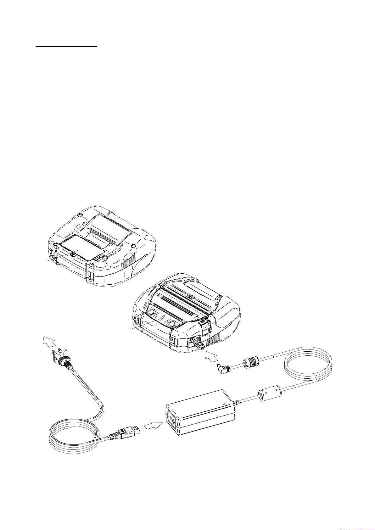
Connecting the AC Adapter to the printer
2
3
4
1
(1) Turn off the printer.
(2) Connect the AC cable to the AC adapter.
(3) Connect the DC plug of the AC adapter to the power connector of the printer.
(4) Connect the AC plug of the AC cable to an outlet. Then, the LED of the AC adapter lights up green.
.
Figure 8-5 Connecting the AC adapter to the Printer
NOTE
Turn off the printer before installing/removing the AC adapter.
◆
When the printer is not used for a long time, unplug the AC cable from an outlet.
◆
HINT
When Auto Activation by AC is enabled, the printer is automatically turned on by inserting
•
the AC plug of the AC cable into an outlet. For details, see "11. FUNCTION SETTINGS".
The AC adapter may get hot when in use. This is normal and not a malfunction.
•
22
Page 26

9. THERMAL PAPER SETTING
The printer uses the thermal paper roll (hereinafter referred to as thermal paper).
Use the thermal paper with printable surface rolled outwards.
Four types of the thermal paper width can be used in the printer. For setting the paper width,
see "13. PAPER WIDTH SETTING".
And, the function settings of the printer differ depending on the used thermal paper.
See "11. FUNCTION SETTINGS" for details.
Thermal Paper Setting
(1) Press the paper cover open button in the direction of the arrow shown in Figure 9-1, and open the
paper cover.
Figure 9-1 Paper Cover Open Button
NOTE
Press the paper cover open button to the end.
◆
If not, the paper cover may be not opened.
23
Page 27

(2) Set the thermal paper into the paper holder with its printing surface facing to the thermal head.
Printing surface
CORRECT
INCORRECT
If the setting direction is wrong, the printer cannot print.
Figure 9-2 Thermal Paper Setting Direction
NOTE
The printer has 2 paper cutters on the paper outlet: one is on the printer side, and the
◆
other is on the paper cover side. Be careful not to cut your fingers by the paper cutters
during setting the thermal paper.
NEVER touch the thermal head immediately after printing because it may get hot.
◆
DO NOT touch the platen and gears in the printer. Doing so may cause loss of printing
◆
quality or damage.
(3) Pull the thermal paper straightly until the tip of the thermal paper appears 5 cm or longer from the
paper outlet.
Make sure that the thermal paper does not slant.
Figure 9-3 Thermal Paper Setting Direction Example
NOTE
If the thermal paper is set into the paper holder at an angle, the thermal paper may not
◆
be ejected straightly. If so, set the thermal paper correctly.
24
Page 28

(4) Push firmly the center of the paper cover (the arrow in Figure 9-4) to close the paper cover.
Figure 9-4 Paper Cover
NOTE
If the paper cover is not completely closed, the ERROR LED indicates "Paper cover
◆
open error" when turning on the printer. In that case, open and close the paper cover
again.
When the paper cover is closed, the top of thermal paper may be colored because of the
◆
friction with a part of the printer. In that case, feed the thermal paper a few centimeters
and cut the top of the thermal paper before starting printing.
(5) When using the marked paper, press the FEED Switch once to feed the paper to the home position.
In this case, the mark mode setting is needed.
See "2.1.8 Mark (Paper) Sensor Specifications" in "MP-A40 SEREIS THERMAL PRINTER
TECHNICAL REFERENCE" for details of the mark mode setting, paper position or specifications.
NOTE
DO NOT cover the paper outlet or hold down the thermal paper ejected. Doing so may
◆
cause a paper jam.
HINT
Leaving the printer with the thermal paper for a long time may cause a paper-feeding
•
problem because the surface of the thermal paper sticks to the thermal head due to the
environmental changes. In that case, open the paper cover to separate the thermal paper
from the thermal head, and then close the paper cover before use.
25
Page 29

Thermal Paper Shape
CORRECT
INCORREC
T
INCORREC
T
CORRECT
INCORRECT
Always use the specified thermal paper. See "21. ACCESSORIES AND CONSUMABLE PARTS" for
details.
NOTE
Use the thermal paper whose maximum diameter is 58 mm or less.
◆
Use the thermal paper whose maximum width is equal or less than the each paper width
◆
+0.5 mm including winding deviation.
DO NOT use the thermal paper with glued or taped end.
◆
Use the thermal paper whose core inside diameter is 12 mm or more for receipt sheet
◆
and 18 mm or more for label sheet.
NOTE
DO NOT use deformed thermal paper. Doing so may cause the printer damaged.
◆
NOTE
In case of using loosened thermal paper roll, rewind the roll before using it.
◆
26
Page 30

10. TEST PRINT
The printer can perform a test print.
In the test print, the firmware version, setting values of function settings, etc. are printed.
Test Print Procedure : Bluetooth Model
(1) Install the thermal paper in the printer as instructed in "9. THERMAL PAPER SETTING".
Ensure that no error occurs, and then turn off the printer.
(2) Press the POWER Switch while holding down the FEED Switch. Release the POWER Switch first.
When the test print is started, release the FEED Switch.
* Bluetooth Communication *
Printer Name: MP-A40
Address: XX:XX:XX:XX:XX:XX
Profile: SPP
Auto Connection: Disable
Inquiry Response: Pairing Mode
Figure 10-2
Bluetooth Information Printing Sample
Table 10-1
Bluetooth Communication Information
Item Description
Figure 10-1
Test Print Sample (Bluetooth Model)
Printer Name Bluetooth Device Name
Address Bluetooth Address
Profile Selected Profile
Auto Connection iOS Auto Connection
Inquiry Response Selected Searching Mode
27
Page 31

(3) After the test print, the mode selection message is printed as shown in Figure 10-3.
To return to the print-ready status, select "0 : Normal Mode". (Press the POWER Switch without
pressing the FEED Switch.)
To select other modes, press the FEED Switch for the number of times corresponding to the
selected mode number, and then press the POWER Switch.
[Mode Select]
0 : Normal Mode
1 : Setting Mode
2 : Wireless ON/OFF Mode
3 : Hex Dump Mode
Press the FEED switch an equal
number of times to the selected number.
After that, press the POWER SW.
Figure 10-3 Mode Selection Message (Bluetooth Model)
28
Page 32

Test Print Procedure: Wireless LAN Model
(1) Install the thermal paper in the printer as instructed in "9. THERMAL PAPER SETTING".
Ensure that no error occurs, and then turn off the printer.
(2) Press the POWER Switch while holding down the FEED Switch. Release the POWER Switch first.
When the test print is started, release the FEED Switch.
Figure 10-4 Test Print Sample (Wireless LAN Model)
29
Page 33

(3) After the test print, the mode selection message is printed as shown in Figure 10-5.
To print Wireless LAN information, select "4 : Print WLAN Information". (Press the FEED Switch 4
times, and then press the POWER Switch.)
The printer starts preparation for printing Wireless LAN information.
[Mode Select]
0 : Normal Mode
1 : Setting Mode
2 : Wireless ON/OFF Mode
3 : Hex Dump Mode
4 : Print WLAN Information
Press the FEED switch an equal
number of times to the selected number.
After that, press the POWER SW.
Figure 10-5 Mode Selection Message (Wireless LAN Model)
It takes about 15 to 30 seconds to start printing Wireless LAN information. Meanwhile, Getting
(4)
Wireless LAN Information Message in Figure 10-6 is printed. Please wait for a while.
Getting WLAN information. Please wait...
Figure 10-6 Getting Wireless LAN Information Message
30
Page 34

After getting Wireless LAN information, Wireless LAN information is printed as a sample shown in
Figure 10-7.
* WLAN Communication *
Mode: Simple AP
Radio: 802.11b/g/n
Country: JP
Channel: Auto
SSID: SII-Printer
Security: None
DHCP Server: Enable
MAC Address: XX:XX:XX:XX:XX:XX
IP Address: 192.168.0.1
Subnet Mask: 255.255.255.0
Gateway Address: 0.0.0.0
Module Ver.: 01.XX.XX
Figure 10-7 Wireless LAN Information Sample
Table 10-2 Wireless LAN Communication Information
Item Description
Mode Selected Wireless LAN Operation Mode
Radio Selected Wireless LAN Standard
US: USA, Canada
Country
JP: Japan
EU: EU, EFTA, Turkey
BR: Brazil
Channel Selected Channel
SSID SSID Setting
Security Selected Security
DHCP Server Selected DHCP Server (in Simple AP Mode)
DHCP Client Selected DHCP Client Mode (in Client Mode)
MAC Address MAC Address
IP Address IP Address*
Subnet Mask Subnet Mask*
Gateway Address Gateway Address*
*: When Wireless LAN Mode is set to Client Mode, IP address, subnet mask and gateway address
obtained from the DHCP server are printed. While waiting for getting information from the DHCP server,
the information is printed as "---,---,---,---". In case of DHCP timeout, the setting value is used and printed.
31
Page 35

(5) After the Wireless LAN information printing, the mode selection message is printed as shown in
Figure 10-5.
To return to the print-ready status, select "0 : Normal Mode". (Press the POWER Switch without
pressing the FEED Switch.)
To select other modes, press the FEED Switch for the number of times corresponding to the
selected mode number, and then press the POWER Switch.
32
Page 36

11. FUNCTION SETTINGS
This printer can set various functions according to use conditions and intended use.
The setting contents are stored in the Memory Switch (hereinafter referred to as MS) in the FLASH
memory mounted in the printer, and it is possible to set MS by using the switches or command input.
This section describes the setting procedure by using the switches.
See "22. MS SETTINGS LIST" for the MS setting list.
NOTE
Be sure to set the value as instructed when "Fixed" is stated for 0 or 1 in the table.
◆
Otherwise, the printer may not work correctly or may crash.
HINT
See "MP-A40 SERIES THERMAL PRINTER TECHNICAL REFERENCE" for details of
•
the function settings by using the switches and other methods.
When neither switch is pressed within 30 seconds after the message is printed, the printer
•
exits the Setting Mode and returns to the print-ready status.
Procedure for Setting Functions Using Switches
To set the functions using the switches, set the printer in the Setting Mode.
To enter the Setting Mode, follow the procedure below.
(1) Install the thermal paper in the printer as instructed in "9. THERMAL PAPER SETTING".
And check that no error occurs, and then turn off the printer.
See "7. LED DISPLAY OF PRINTER" for the error status.
(2) Press the POWER Switch while holding down the FEED Switch. Release the POWER Switch first.
When the test print is started, release the FEED Switch.
(3) After the test print, the mode selection message is printed as shown in Figure 11-1.
To enter the Setting Mode, select "1 : Setting Mode". (Press the FEED Switch once, and then press
the POWER Switch.)
[Mode Select]
0 : Normal Mode
1 : Setting Mode
2 : Wireless ON/OFF Mode
3 : Hex Dump Mode
4 : Print WLAN Information
Press the FEED switch an equal
number of times to the selected number.
After that, press the POWER SW.
・"4 : Print WLAN Information" is printed only for the Wireless LAN model.
・When pressing the FEED Switch once, "1 : Setting Mode" is selected.
・When pressing the POWER Switch without pressing the FEED Switch, "0 : Normal Mode" is selected.
Figure 11-1 Mode Selection Message
33
Page 37

(4) When the printer enters the Setting Mode, a message for selecting MS to be set is printed as shown
in Figure 11-2.
Press the FEED Switch the number of times corresponding to the selected MS number, and then
press the POWER Switch.
[MS Selection]
0 : Exit
1 : MS1
2 : MS2
3 : MS3
4 : MS4
5 : MS5
6: MS7,8
7 : MS9
8 : MS10
9 : MS13
10: I/F Setting
11: USB Setting
12: International Character
13: Character Code Table
14: Default Setting
Press the FEED switch an equal number of times to the selected
number. After that, press the POWER SW.
・When pressing the FEED Switch once, "1 : MS1" is selected.
・When pressing the POWER Switch without pressing the FEED Switch, "0: Exit" is selected.
・"10: I/F Setting" is printed only for Bluetooth model. When setting Bluetooth connection,
select this.
Figure 11-2 MS Selection Message
(5) A message for selecting the functions assigned to the selected MS is printed as a sample shown in
Figure 11-3.
Press the FEED Switch the number of times corresponding to the selected function number, and
then press the POWER Switch.
[Function selection of MS1]
0 : Return to MS selection
1 : Interface
2 : Mark Mode
3 : Command System
4 : Error Through
5 : Auto Activation by AC
6 : Response Data Discarding
Press the FEED switch an equal number of times to the selected
number. After that, press the POWER SW.
・When pressing the FEED Switch 3 times, "3 : Command System" is selected.
・When pressing the POWER Switch without pressing the FEED Switch, "0 : Return to MS Selection"
is selected.
Figure 11-3 Function Selection Message
(Example: Selected MS1)
34
Page 38

(6) A message for selecting the setting value of the selected function is printed as a sample shown in
number. After that, press the POWER SW.
Figure 11-4.
Press the FEED Switch the number of times corresponding to the selected setting value number,
and then press the POWER Switch.
[Command System]
0 : Return to function selection
1 : ESC/POS
2 : HTML
3 : CPCL
Press the FEED switch an equal number of times to the selected
・When pressing the FEED Switch once, "1 : ESC/POS" is selected.
Figure 11-4 Setting Value Selection Message
(Example: Selected Command System)
A message for confirming the selected setting value is printed as a sample shown in Figure 11-5.
(7)
[Command System]
Set ESC/POS
Save setting : Feed SW
Discard setting : Power SW
Figure 11-5 Setting Value Confirmation Message
(Example: Selected ESC/POS)
To save the setting value to the memory, press the FEED Switch. Figure 11-2 MS Selection
Message is printed.
To discard the selected item, press the POWER Switch. Function Selection Message is printed
as a sample shown in Figure 11-3. If select "0 Return to MS Selection", function selection is
not performed, and Figure 11-2 MS Selection Message is printed. (Press the POWER Switch
without pressing the FEED Switch.)
To continue to set functions, return to (4).
(8) To exit the Setting Mode, select "0 : Exit" in Figure 11-2 MS Selection Message. (Press the POWER
Switch without pressing the FEED Switch.)
The test print and Figure 11-1 Mode Selection Message printing start again. Verify that the functions
are properly set.
To return to the print-ready status, select "0 : Normal Mode" in Mode Selection Message. (Press the
POWER Switch without pressing the FEED Switch.)
To set functions again, return to (3).
35
Page 39

12. CONNECTING TO THE HOST DEVICE
The printer supports USB communication and Bluetooth communication or Wireless LAN
communication.
Select the Bluetooth model or Wireless LAN model depending on the communication method to use.
• Bluetooth model (MP-A40-Bxxxxxx) : Bluetooth + USB
• Wireless LAN model (MP-A40-Wxxxxxx) : Wireless LAN + USB
The function settings of the printer differ depending on the communication method to use. See "MP-A40
SERIES THERMAL PRINTER TECHNICAL REFERENCE" for details.
An optional USB interface cable is required to perform USB communication.
See "20. SPECIFICATIONS" for details of the interface specifications.
The communication speed may be reduced depending on processing by software or print contents.
Wireless communication is required to be disabled in places where its use is prohibited.
To switch wireless on/off, press the POWER Switch 3 times within 3 seconds while the power is on.
The WIRELESS LED lights on or blinks when wireless communication is enabled.
The WIRELESS LED lights off when wireless communication is disabled.
36
Page 40

USB Communication
(1) Ensure that the power of the printer is off.
(2) Connect the USB interface cable to the USB interface connector of the printer.
(3) Turn on the printer, and send data from the host device to the printer.
(4) Verify that the data is printed correctly.
Figure 12-1 Interface Cable for USB Communication
NOTE
When connecting the USB interface cable to the USB interface connector, push the plug
◆
to the end.
When connecting or disconnecting the interface cable, hold the connector, not the
◆
cable.
37
Page 41

Bluetooth Communication
(1) When the USB interface cable is connected to the printer, disconnect it from the printer.
(2) Turn on the printer and pair it with the host device.
In the factory shipment state, the printer enters pairing mode for about 60 seconds by pushing the
power switch for 7 seconds or more. When the pairing mode starts, the WIRELESS LED blinks
twice per second. During this time, pair the printer with the host device.
Pairing is conducted by SSP (Simple Secure Pairing), however, PIN code is used when the host
device does not support SSP. The PIN code is "0000" at the shipping.
(3) Conduct Bluetooth connection with the host device.
After the Bluetooth connection is established, the WIRELESS LED lights up.
(4) Check the communication status on the host device.
(5) Send data from the host device, and verify that the data is printed correctly.
WARNING
The printer may affect medical or other electronic devices. Obtain information and data
◆
concerning influence due to radio interference from the respective manufacturers or
dealers.
When using the printer in medical institutions, follow their guidelines.
◆
DO NOT use the printer in any area or district where its use is prohibited.
◆
HINT
The distance of communication is approximately 10 m. However, the distance may differ
•
depending on the radio interference and environment.
When the printer is connected from an iPhone or iPad by Bluetooth, "Profile" should be
•
set to "iAP2". When connected from an Android terminal or PC, "Profile" should be set to
"SPP".
The setting is "SPP" at the shipping.
•
To switch SPP/iAP2, press the POWER Switch 5 times within 3 seconds while the power
•
is on.
38
Page 42

Wireless LAN Communication
(1) When the USB interface cable is connected to the printer, disconnect it from the printer.
(2) Turn on the printer and connect it to the host device by wireless communication.
In the factory shipment state, the function settings are as follows:
Mode : Simple AP (simple access point)
Communication Standard : 802.11b/g/n (2.4GHz frequency range)
SSID : SII-Printer
Security : None
DHCP Server : Enable
Printer IP address : mina192.168.0.1
(3) View the page "http://192.168.0.1" from the Web browser.
The printer setting screen is displayed. Make necessary settings.
These settings are enabled after rebooting.
(4) Check the communication status on the host device.
(5) Send data from the host device, and verify that the data is printed correctly.
WARNING
The printer may affect medical or other electronic devices. Obtain information and data
◆
concerning influence due to radio interference from the respective manufacturers or
dealers.
When using the printer in medical institutions, follow their guidelines.
◆
DO NOT use the printer in any area or district where its use is prohibited.
◆
39
Page 43

13. PAPER WIDTH SETTING
Partition Plate
Attachment
80
Partition Plate
Attachment
100
Partition Plate
80mm
p3
10
0mm
p2
105mm
p1
This printer can use thermal paper of 105 mm, 100 mm, and 80 mm in width by installing the partition
plate and partition plate attachments included with the printer.
The partition plate attachment (hereinafter referred to as attachment) has 2 types.
Figure 13-1 Partition Plate and Attachments
In accordance with the thermal paper width, install the partition plate and each attachment to the printer.
Table 13-1 below shows the combination of the partition and attachment.
See Figure 13-2 for the installing position of the partition plate and attachment at each paper width.
Table 13-1 Partition Plate and Attachment Combination List
Thermal Paper Width
112 mm 105 mm 100 mm 80 mm
Partition Plate -
Partition Plate Attachment 100 - - Partition Plate Attachment 80 - - -
Partition Plate Position (Figure 13-2) - p1 p2 p3
Figure 13-2 Partition Plate and Attachment Position
40
Page 44

d
D
e
g
f
F
E
G
Installing Partition Plate
This section describes how to install the partition plate and attachment for 80 mm paper width.
(1) Turn off the printer.
(2) Remove the battery pack from the printer. When the AC adapter is connected, unplug the AC plug of
the AC cable from an outlet.
(3) Press the paper cover open button to open the paper cover.
(4) Combine the part "D" of the partition plate with the part "d" of Attachment 80 as shown in Figure
13-3.
Figure 13-3 Combining Partition Plate with Attachment
Fix the tabs "e", "f", and "g" of the partition plate to the grooves "E","F", and "G" of the printer by the
(5)
following procedure 1 to 3.
The printer has the same-shaped grooves by each of the paper width.
Figure 13-4 Partition Plate Installation (1)
41
Page 45

1. Align the tab "e" of the partition plate to the groove "E" of the printer as shown in Figure 13-5.
e
g
Figure 13-5 Partition Plate Installation (2)
2. Rotate the partition plate clockwise with the tab "e" as a supporting point, and set the tab "f" into
the groove "F" of the printer.
3. Push the partition plate until the tab "g" of the partition plate is locked in the groove "G" of the
printer as shown in Figure 13-6.
Figure 13-6 Partition Plate Installation (3)
Make sure that the partition plate is installed securely into the printer.
(6)
• Ensure the tab "e" is fixed in the groove "E"
• Ensure the tab "f" is fixed in the groove "F"
• Ensure the tab "g" is fixed in the groove "G"
(7) When the paper width is set by the partition plate, set the paper width in General Setting 3 (MS3) of
the Function Settings.
See "4.2 FUNCTION SETTINGS (MS)" in "MP-A40 SERIES THERMAL PRINTER TECHNICAL
REFERENCE" for details.
42
Page 46

Removing Partition Plate
h
Follow the below procedure to remove the partition plate from the printer.
(1) Pull up the part "h" of the partition plate pressing in the direction of the arrow as shown in the figure
below.
Figure 13-7 Partition Plate Removal
NOTE
The printer has 2 paper cutters on the paper outlet: one is on the printer side, and the
◆
other is on the paper cover side. When installing/removing the partition plate, be careful
not to cut your fingers by the paper cutters.
Set the paper width before using the printer for the first time. DO NOT change the paper
◆
width after starting to use the printer. Doing so may damage the printer.
When the thermal paper smaller than 112 mm in width is used with using the partition
◆
plate, rubber crumbs of the platen may be generated because the platen contacts with
the thermal head. Remove rubber crumbs regularly to maintain the printing quality.
43
Page 47

14. INSTALLING BELT CLIP / SHOULDER STRAP
j
J
The belt clip and the shoulder strap convenient for carrying the printer can be attached to this printer.
The belt clip is included with the printer.
The shoulder strap is an optional accessory. See "21. ACCESSORIES AND CONSUMABLE PARTS",
and be sure to purchase our specified products listed on the reference.
Installing Belt Clip
(1) Turn off the printer.
(2) Remove the battery pack from the printer.
When the AC adapter is connected, disconnect the AC plug of AC cable from an outlet.
(3) Insert the part "j" of the belt clip into the hole "J" of the printer in the direction of the arrow as shown
in Figure 14-1.
The belt clip cannot be installed in wrong direction.
Figure 14-1 Belt Clip Installation (1)
44
Page 48

(4) Rotate the belt clip 90 degrees.
k
Figure 14-2 Belt Clip Installation (2)
Install the battery pack in the printer.
(5)
(6) Hook the part "k" of the belt clip in Figure 14-3 to your belt.
Figure 14-3 Belt Clip Installation (3)
NOTE
Be sure to install the battery pack to the printer when using the belt clip because the belt
◆
clip comes off too easily from the printer without installing the battery pack. Dropped
printer may cause personal injury or malfunction.
Avoid the direct skin contact with the battery pack while using the belt clip. Prolonged
◆
skin contact may cause low-temperature burns.
45
Page 49

Installing Shoulder Strap
(1) Pass the tip of shoulder strap through the installation hole of the printer as shown in Figure 14-4.
Loosen the shoulder strap at the adjuster part.
Figure 14-4 Shoulder Strap Installation (1)
(2) Pass the tip of folded shoulder strap through the ring as shown in Figure 14-5.
Figure 14-5 Shoulder Strap Installation (2)
46
Page 50

(3) As shown in Figure 14-6, pass the tip of shoulder strap through the adjuster hole on farther side
from the printer.
Figure 14-6 Shoulder Strap Installation (3)
(4) As shown in Figure 14-7, pass the tip of shoulder strap through the adjuster hole on closer side from
the printer.
And then, pass the tip of shoulder strap through the ring again.
Figure 14-7 Shoulder Strap Installation (4)
47
Page 51

(5) As shown in Figure 17-8, install the other shoulder strap by the same procedure described (1) to (4).
Tighten the looseness of adjuster part and adjust the length of the shoulder strap.
Figure 14-8 Shoulder Strap Installation (5)
NOTE
Be sure to install the shoulder strap to the printer securely when using the shoulder
◆
strap. Dropped printer may cause personal injury or malfunction.
Avoid the direct skin contact with the battery pack while using the shoulder strap.
◆
Prolonged skin contact may cause low-temperature burns.
48
Page 52

15. CHARGING BATTERY PACK
The battery pack can be charged using the printer or battery charger.
By the Printer
1. Charged from an AC power supply using the AC adapter.
2. Charged from an accessory socket of a car using the car charger.
By the Battery Charger
3. Charged from an AC power supply using the AC adapter.
This chapter describes how to charge from an AC power supply by the printer using the AC adapter.
The AC adapter requires the specified AC cable.
Be sure to see "16. CHARGING BY CAR CHARGER" for the charging method by the car charger.
And be sure to see "17. CHARGING BY BATTERY CHARGER" for the charging method by the battery
charger.
The battery pack is partially charged prior to shipping and provides sufficient power to check the printer
operation. To use the printer for an extended time, fully charge the battery pack.
This battery pack does not need to be used up or discharged before charging.
The battery pack, the AC adapter, and the AC cable are optional accessories.
See "20. SPECIFICATIONS" and "21. ACCESSORIES AND CONSUMABLE PARTS", and be sure to
purchase our specified products listed on these references.
NOTE
DO NOT remove the battery during charging.
◆
The battery pack should be charged at 32°F to 104°F (0°C to 40°C).
◆
Charging by Printer and AC Adapter
There are 2 methods for charging the battery pack by the printer using the AC adapter.
• Normal charging : Charging starts regardless of a battery remaining capacity.
• Long life charging : Repeating to charge and discharge the battery pack with
enough battery remaining capacity may accelerate the battery
pack deterioration.
To prevent this, charging starts when a battery remaining
capacity falls down battery level 2 or less.
For the battery remaining capacity and the error status, see "7. LED DISPLAY OF PRINTER".
Select the charging method depending on the procedure.
49
Page 53
Normal Charging
3
4
5
1
2
Before connecting the AC adapter, install the battery pack in the printer.
(1) Ensure that the printer power is off.
(2) Install the battery pack in the printer.
(3) Connect the AC cable to the AC adapter.
(4) Plug the DC plug of the AC adapter to the power connector of the printer.
(5) Plug the AC plug of the AC cable to an outlet.
(6) The printer turns on automatically.
After the POWER LED displays the battery remaining capacity for approximate 3 seconds, the
POWER LED changes to orange, and then charging starts.
During charging, the POWER LED lights on orange.
(7) When the charging is successfully complete to full charge, the power is shut off automatically.
In case that a battery error occurs during charging, the ERROR LED displays the error status.
When it happens, the power is not shut off automatically.
Figure 15-1 Normal Charging by AC Adapter
50
Page 54

Long Life Charging
2
3
4
1
5
6
After connecting the AC adapter, install the battery pack in the printer.
When the battery pack has already been installed, remove it from the printer.
(1) Ensure that the printer power is off.
(2) Connect the AC cable to the AC adapter.
(3) Plug the DC plug of the AC adapter to the power connector of the printer.
(4) Plug the AC plug of the AC cable to an outlet.
(5) Install the battery pack to the printer.
(6) Turn on the printer.
After the POWER LED displays the battery remaining capacity for approximate 3 seconds,
the POWER LED turns orange and charging starts when the battery remaining capacity is battery
level 2 or less.
When the battery remaining capacity is battery level 1, the POWER LED stays displaying the battery
remaining capacity, and charging does not start.
During charging, the POWER LED lights on orange.
(7) When the charging is successfully complete to full charge, the POWER LED turns to green.
The power is not shut off automatically.
In case that a battery error occurs during charging, the ERROR LED displays the error status.
Figure 15-2 Long Life Charging by AC adapter
51
Page 55

HINT
The printer can print or receive data while charging by the printer and AC adapter.
•
During printing, the POWER LED displays the battery remaining capacity continuously
and the printer pauses charging.
After printing is completed, the printer resumes charging, and the light of the POWER
LED changes to orange.
When the printer performs printing or receiving data during charging with the normal
charging method, the power is not shut off automatically even when charging is
completed.
To stop charging, press the power switch to turn off the power.
•
To resume charging, press the power switch again.
For the long life charging method, please note that further charging will not be continued if
the remaining capacity of the battery pack has recovered to the battery level 1 at the time
of charge resumption.
When resuming charging by the above procedure during normal charging, the charging
•
method is switched to the long life charging method, and therefore the power is not shut
off automatically even when charging is completed. To resume charging with the normal
charging method, turn off the printer, then unplug the AC plug of the AC adapter from the
outlet, and plug it again.
The charging time depends on the ambient temperature and the voltage level of the
•
battery pack. Normally, it takes about 4 hours to complete charging after running down
the battery pack.
The AC adapter may get hot when in use. This is normal and not a malfunction.
•
52
Page 56

16. CHARGING BY CAR CHARGER
The battery pack can be charged by connecting a car accessory socket and the printer using the car
charger.
The car charger is only for charging. Even if the car charger is connected to the printer, the printer cannot
print without the battery pack.
Charging the battery pack by the car charger is possible while the car engine is running or in the
accessory position. Ensure that the car battery remaining capacity is sufficient before using the car
charger in accessory position.
The battery pack and the car charger are optional accessories. See "20. SPECIFICATIONS" and
"21. ACCESSORIES AND CONSUMABLE PARTS", and be sure to purchase our specified products
listed on these references.
NOTE
DO NOT remove the battery pack during charging.
◆
DO NOT connect the battery charger to the car charger.
◆
The battery pack should be charged at 32°F to 104°F (0°C to 40°C).
◆
After using the car charger, unplug the cigar plug from the car accessory socket.
◆
DO NOT print out during a vehicle driving. Ejected thermal paper may hinder a vehicle
◆
driving.
53
Page 57

1
2
3
Each Part of Car Charger
Figure 16-1 Each Part of Car Charger (CC-A12-A1)
1 DC Plug
The DC plug connects to the power connecter.
2 Cigar Plug
The cigar plug connects to a car accessory socket.
3 LED
The LED displays the activate state.
The LED lights on green when the car engine is running or in the accessory position.
Charging by Printer and Car Charger
There are 2 methods for charging the battery pack by the printer using the car charger.
• Normal charging : Charging starts regardless of a battery remaining capacity.
• Long life charging : Repeating to charge and discharge the battery pack with
enough battery remaining capacity may accelerate the battery
pack deterioration.
To prevent this, charging starts when a battery remaining
capacity falls down battery level 2 or less.
For the battery remaining capacity and the error status, see "7. LED DISPLAY OF PRINTER".
Select the charging method depending on the procedure.
54
Page 58

Normal Charging
3
4
1
2
Before connecting the car charger, install the battery pack in the printer.
Ensure that the car engine is running or in the accessory position.
(1) Ensure that the printer power is off.
(2) Install the battery pack in the printer.
(3) Connect the DC plug of the car charger to the power connector of the printer.
(4) Plug the cigar plug of the car charger to a car accessory socket.
(5) The printer turns on automatically.
After the POWER LED displays the battery remaining capacity for approximate 3 seconds, the
POWER LED changes to orange, and then charging starts.
During charging, the POWER LED lights on orange.
(6) When the charging is successfully complete to full charge, the power is shut off automatically.
In case that a battery error occurs during charging, the ERROR LED displays the error status.
When it happens, the power is not shut off automatically.
Figure 16-2 Normal Charging by Car Charger
55
Page 59

Long Life Charging
2
3
1
4
5
After connecting the car charger, install the battery pack in the printer.
When the battery pack has already been installed, remove it from the printer.
Ensure that the car engine is running or in the accessory position.
(1) Ensure that the printer power is off.
(2) Connect the DC plug of the car charger to the power connector of the printer.
(3) Plug the cigar plug of the car charger to a car accessory socket.
(4) Install the battery pack in the printer.
(5) Turn on the printer.
After the POWER LED displays the battery remaining capacity for approximate 3 seconds,
the POWER LED turns orange and charging starts when the battery remaining capacity is battery
level 2 or less.
When the battery remaining capacity is battery level 1, the POWER LED stays displaying the battery
remaining capacity, and charging does not start.
During charging, the POWER LED lights on orange.
(6) When the charging is successfully complete to full charge, the POWER LED turns to green.
The power is not shut off automatically.
In case that a battery error occurs during charging, the ERROR LED displays the error status.
Figure 16-3 Long Life Charging by Car Charger
56
Page 60

HINT
The printer can print or receive data while charging by the printer and car charger.
•
But note that the power for operating the printer is supplied from the battery.
During printing, the POWER LED displays the battery remaining capacity continuously
and the printer pauses charging.
After printing is completed, the printer resumes charging, and the light of the POWER
LED changes to orange.
When the printer performs printing or receiving data during charging with the normal
charging method, the power is not shut off automatically even when charging is
completed.
To stop charging, press the power switch to turn off the power.
•
To resume charging, press the power switch again.
For the long life charging method, please note that further charging will not be continued if
the remaining capacity of the battery pack has recovered to the battery level 1 at the time
of charge resumption.
When resuming charging by the above procedure during normal charging, the charging
•
method is switched to the long life charging method, and therefore the power is not shut
off automatically even when changing is completed. To resume charging with the normal
charging method, turn off the printer, then unplug the cigar plug from the car accessory
socket, and plug it again.
The charging time depends on the ambient temperature and the voltage level of the
•
battery pack. Normally, it takes about 4 hours to complete charging after running down
the battery pack.
The car charger may get hot when in use. This is normal and not a malfunction.
•
57
Page 61

17. CHARGING BY BATTERY CHARGER
1
1
2
2
2
2
2
The battery pack can be charged using the battery charger.
To use the battery charger, the AC adapter and the AC cable are required.
The battery pack, the AC adapter, the AC cable, and the battery charger are optional accessories.
See "20. SPECIFICATIONS" and "21. ACCESSORIES AND CONSUMABLE PARTS", and be sure to
purchase our specified products listed on these references.
There are 2 specified battery chargers; one is "PWC-A071-A1" that can charge 1 battery pack, and the
other is a quad battery charger "PWC-A074-A1" that can charge maximum 4 battery packs.
NOTE
The battery pack should be charged at 32°F to 104°F (0°C to 40°C).
◆
Keep the terminal of the battery charger away from dust and metal objects.
◆
DO NOT install the battery pack when installing/removing the AC adapter.
◆
After using the battery charger, unplug the AC cable from the outlet.
◆
Remove the battery pack after charging.
◆
DO NOT connect the car charger to the battery charger.
◆
Each Part of Battery Charger
PWC-A071-A1 PWC-A074-A1
Figure 17-1 Each Part of Battery Charger
1 Power Connector
The DC plug of the AC adapter is connected.
2 LED
The LED displays the activate state.
58
Page 62

0.2s
0.8s
0.1s
0.7s
0.1s
0
.1s
0.1
s
LED Display of Battery Charger
Table 17-1 Battery Charger Status
Battery Pack Status
Not installed Green On
Charging completed Green On
Charging Orange On
Charging battery temperature error Red Blink-2
Battery installation error Red Blink-3
Battery error Red Blink-4
Hardware error Red On
Table 17-2 Blink Pattern
Status Pattern
Color
LED
Lighting
Pattern
Blink-2
Blink-3
Blink-4
59
Page 63

1
2
3
Connecting the Battery Charger and the AC adapter
This section describes how to connect the battery charger PWC-A071-A1 and the AC adapter.
When the battery pack has already been installed, remove it from the battery charger.
(1) Connect the AC cable to the AC adapter.
(2) Plug the DC plug of AC adapter to the power connector of the battery charger.
Fix the cable of the AC adapter in the groove of the battery charger as shown in Figure 17-3.
(The cable can be fixed on either the left or right groove.)
(3) Plug the AC plug of the AC cable to an outlet.
The LED of the battery charger changes from lighting off to green lighting.
Figure 17-2 Battery Charger, AC Adapter and AC Cable Connection
Figure 17-3 Fixing Cable
60
Page 64

a
b
B
A
Charging Battery Pack by Battery Charger
This section describes how to charge the battery pack by the battery charger PWC-A071-A1.
The battery pack is installed to the battery charger in the direction as shown in Figure 17-4.
The battery pack cannot be inserted in the wrong direction.
Figure 17-4 Battery Pack Direction
(1) Insert the tab "a" of the battery pack under the groove "A" of the battery charger.
Figure 17-5 Battery Pack Installation (1)
(2) Press the battery pack in the direction of the arrow in Figure 17-6 until the tab "b" of the battery pack
locks in the groove "B" of the battery charger.
Figure 17-6 Battery Pack Installation (2)
61
Page 65

c
1
2
(3) Make sure that the battery pack is installed to the battery charger correctly.
• Ensure the tab "a" of the battery pack is inserted under the groove "A" of the battery charger.
• Ensure the tab "b" of the battery pack is locked in the groove "B" of the battery charger.
(4) The LED of the battery charger changes to orange, and then charging starts.
During charging, the POWER LED lights on orange.
When the LED doesn't turn to orange, install the battery pack again.
In case the LED doesn't turn to orange even if the battery pack is installed again, take action in
accordance with "■Error Handling Procedures".
(5) When charging is completed, the LED of the battery charger changes to green.
Press the lever "c" of the battery pack in the direction of the arrow 1 in Figure 17-7, and remove the
battery pack by pulling up in the direction of the arrow 2.
It is not a problem to remove the battery pack during charging.
In case that a battery installation error or battery error occurs during charging, the LED starts to blink
in red.
When it happens, take action in accordance with "■Error Handling Procedures".
Figure 17-7 Battery Pack Removal from Battery Charger
HINT
The charging time depends on the ambient temperature and the voltage level of the
•
battery pack. Normally, using the battery charger "PWC-A071-A1", it takes about 4 hours
to complete charging after running down the battery pack. Using the quad battery charger
"PWC-A074-A1", it takes about 5 hours.
The battery charger and the AC adapter may get hot when in use. This is normal and not
•
a malfunction.
62
Page 66

Error Handling Procedure
Table 17-3 Error Handling Procedure
Phenomenon Possible Cause Corrective Action
LED doesn't light up The battery charger doesn't connect
to the power supply.
The AC adapter is failed or AC
cable is broken.
The battery charger is failed. Replace the battery charger with a
LED displays other than
green lighting without the
battery pack
LED displays charging
temperature error
LED displays battery
installation error
LED displays battery error The battery pack is failed. Replace the battery pack with a new
LED displays hardware error The battery charger or AC adapter
The battery charger is failed. Replace the battery charger with a
The battery pack temperature is out
of the operating temperature range
(charging).
The battery pack is installed in the
wrong direction.
Contact failure of a terminal of the
battery pack
The battery pack is failed. Replace the battery pack with a new
is failed.
Certainly connect the battery
charger to the AC adapter and the
AC cable to receive the power.
Replace the AC adapter or AC
cable with a new one.
new one.
new one.
Charging automatically resumes
when the battery pack temperature
is within the operating temperature
range (charging).
Wait for a while in the place where
the ambient temperature is 32°F to
104°F (0°C to 40°C).
Install the battery pack again.
Remove the battery pack from the
battery charger, clean the terminal,
and install it again.
one.
one.
Replace the battery charger or AC
adapter with a new one.
63
Page 67

Mounting to Wall
37 ±1
PWC-A071-A1
PWC-A074-A1
22
2
±1
This battery charger can be mounted to a wall with using the bottom holes shown in Figure 17-8.
• Recommended screw: pan head screw 3 mm
(head shape: φ5.5 mm, head size: 2 mm)
Mounting Size
Figure 17-8 Bottom of Battery Charger
NOTE
Check the place and the material/structure of the wall, and then install the battery
◆
charger securely. Injury or destruction of property might occur by dropping off.
64
Page 68

18. PRINTER MAINTENANCE
The thermal head of the printer does not require user maintenance.
When paper powder accumulates, cleaning the thermal head can maintain the print quality for an
extended period of time.
Cleaning Thermal Head/Platen
(1) Turn off the printer.
(2) Remove the battery pack from the printer.
When the AC adapter is connected, unplug the AC plug of the AC cable from an outlet.
(3) Open the paper cover.
(4) Clean the thermal head and/or the platen with a cotton swab moistened with a small amount of ethyl
alcohol. (See Figure 18-1.)
Figure 18-1 Thermal Head / Platen Cleaning
Wait until any ethyl alcohol remaining on the thermal head and the platen dries out completely, and
(5)
then close the paper cover.
NOTE
Clean the thermal head after it cools down.
◆
Be sure to wipe the thermal head with a cotton swab or other soft material.
◆
The printer has 2 paper cutters on the paper outlet: one is on the printer side, and the
◆
other is on the paper cover side. Be careful not to cut your fingers by the paper cutters
during cleaning.
DO NOT touch the gear of the platen. Doing so may cause loss of printing quality or
◆
damage.
65
Page 69

19. TROUBLESHOOTING
Check the following points before requesting for repair:
The power does not turn on
• Is specified battery pack or AC adapter being used?
• Is the battery pack sufficiently charged?
• Is the battery pack installed correctly?
• Are the AC cable and the AC adapter connected correctly?
• Are the AC adapter and the printer connected correctly?
The printer does not print or connect
• Is the interface cable connected correctly?
• Are the specifications of the interface cable conformed to its specifications of this manual being
used?
• Are used communication method and the function settings of the printer correct?
• Is the Bluetooth / Wireless LAN communication status normal?
• Is the communication condition between the printer and the host device correct?
• Is the specified thermal paper being used? Is the paper orientation (surface/back) correct?
An error is displayed
• See "7. LED DISPLAY OF PRINTER".
• Are the function settings of the printer correct?
The battery pack cannot be installed
• Is the battery pack correctly oriented?
• Is the specified battery pack being used?
The battery runs out soon even if charged
• Has the battery been charged correctly?
• If the battery pack is charged correctly but does not last for a long time, it is almost dead.
Replace it with a new one.
66
Page 70

20. SPECIFICATIONS
Printer Specifications
Item Specifications
Model MP-A40-B06JK1 (Bluetooth Model)
MP-A40-W06JK1 (Wireless LAN Model)
Printing method Thermal printing
Dot density 8 dots/mm
Paper width / Printing width 80 mm / 72 mm (576 dots)
(Number of effective dots) 100 mm / 92 mm (736 dots)
105 mm / 97 mm (776 dots)
112 mm / 104 mm (832 dots)
Number of characters per line
16 dots × 8 dots 72 digits
Paper width 100 mm: 24 dots × 12 dots 61 digits
16 dots × 8 dots 92 digits
Paper width 105 mm: 24 dots × 12 dots 64 digits
16 dots × 8 dots 97 digits
Paper width 112 mm: 24 dots × 12 dots 69 digits
16 dots × 8 dots 104 digits
Character size 1-byte: H 24 dots × W 12 dots, H 16 dots × W 8 dots
(H × W) 2-byte: H 24 dots × W 24 dots, H 16 dots × W 16 dots
Printing speed max. 105 mm/s
Operating temperature -4°F to 122°F (-20°C to 50°C)
Relative humidity*2 10%RH to 90%RH
Dimensions (W × D × H) 156 mm × 152 mm × 71 mm
Mass Approx. 760 g
(including the battery pack, excluding the thermal paper)
Falling resistance 2 m (6.6 feet)
Dust and drip proof IP54*3
*1: The number is for 1-byte character, and when character spacing is 0 dots.
*2: See "MP-A40 SERIES THERMAL PRINTER TECHNICAL REFERENCE" for the certifiable humidity range at each
temperature.
*3: This number is test result based on SII procedures, not a guaranteed value.
*1
Paper width 80 mm: 24 dots × 12 dots 48 digits
*3
AC Adapter Specifications (Specified Accessories)
Item Specifications
Model PW-D0940-W2
Input voltage AC100 to 240 V, 50/60 Hz
Rated output DC9.0 V, 4 A
Operating temperature 32°F to 104°F (0°C to 40°C)
Dimensions (W × D × H) 53 mm × 114 mm × 37 mm*
Mass Approx. 318 g
*: Excluding the cable.
67
Page 71

Battery Pack Specifications (Specified Accessories)
Item Specifications
Model BP-A0720-A1
Battery Lithium ion
Rated voltage DC 7.4 V
Rated capacity 1950 mAh
Operating temperature -4°F to 122°F (-20°C to 50°C) (printing)
32°F to 104°F ( 0°C to 40°C) (charging)
Mass Approx. 119 g
Battery Charger Specifications (Specified Accessories)
Item Specifications
Model PWC-A071-A1
Input voltage DC9.0 V
Specified battery BP-A0720-A1
Operating temperature 32°F to 104°F (0°C to 40°C)
Dimensions (W × D × H) 54 mm × 123 mm × 41.3 mm
Mass Approx. 82 g
Quad Battery Charger Specifications (Specified Accessories)
Item Specifications
Model PWC-A074-A1
Input voltage DC9.0 V
Specified battery BP-A0720-A1
Operating temperature 32°F to 104°F (0°C to 40°C)
Dimensions (W × D × H) 240 mm × 123 mm × 41.3 mm
Mass Approx. 304 g
Car Charger Specifications (Specified Accessories)
Item Specifications
Model CC-A12-A1
Input voltage DC12.0 V, DC24.0 V
Rated output DC12.0 V, 1.5 A
Operating temperature 32°F to 104°F (0°C to 40°C)
Dimensions (W × D × H) 107 mm × 38 mm × 20.4 mm*
Mass Approx. 70 g
*: Excluding the cable.
68
Page 72

Interface Specifications
USB interface specifications
Item Specifications
Version Ver. 2.0
Printer data transmission mode Bulk transfer (12 Mbps)
Bluetooth interface specifications
tem Specifications
Version Ver. 4.1
Transmission power class Class 2
Profile SPP, iAP2
Wireless LAN interface specifications
Item Specifications
Communication Standard 802.11b/g/n, 802.11a/n
Network Configuration Infrastructure
Station type Access Point (Simple AP mode), Client (Client mode)
Certification/encryption Open, WEP, WPA-PSK, WPA2-PSK, EAP-TTLS*, PEAP*
*: For Client mode only
69
Page 73

Sale Destinations
Sale destinations for the printer are listed below.
Country/Region*1 Bluetooth Model Wireless LAN Model
Japan
USA
Canada
EU
EFTA
MP-A40-B06JK1
MP-A40-W06JK1J
MP-A40-W06JK1U
MP-A40-W06JK1E
Turkey
Brazil MP-A40-W06JK1B
*1: Ask your SII sales representative when you want to operate the products in countries/regions
other than those listed above.
*2: The model differs by country/region.
Sale destinations for the specified accessories are listed below.
Country/Region*1 Battery Pack AC Adapter
Japan
Battery
Charger
Car Charger AC Cable
CB-JP04-18A-E
USA, Canada CB-US04-18A-E
EU (except UK)
EFTA
Turkey
BP-A0720-A1 PW-D0940-W2
PWC-A071-A1
PWC-A074-A1
CC-A12-A1
CB-CE01-18B-E
UK CB-UK01-20A-E
Brazil *2
*1: Ask your SII sales representative when you want to operate the products in countries/regions other than those listed above.
*2: Use the AC cable of 2.0 meters long that complies with safety standards in Brazil.
70
Page 74

21. ACCESSORIES AND CONSUMABLE PARTS
Specified Accessories
Name Model
Battery pack BP-A0720-A1
AC adapter PW-D0940-W2
AC cable* CB-JP04-18A-E
CB-US04-18A-E
CB-CE01-18B-E
CB-UK01-20A-E
Battery charger PWC-A071-A1
PWC-A074-A1
Car charger CC-A12-A1
Shoulder strap STR-A03-1
USB interface cable IFC-U01-1-E
*: The shape of an outlet differs by country. Confirm it before using.
Specified Thermal Paper
*1 *2
Paper Type Model Manufacturer
Receipt sheet TF50KS-E2D Nippon Paper
PD160R Oji Paper
P220VBB-1 Mitsubishi Paper Mills.
Alpha400-2.1*3 Appvion
KT48PF Papierfabrik August Koehler
F5041 Mitsubishi HiTec Paper
Label sheet*4 HW76MW Lintec
KIP370
*5
Kanzaki Specialty Papers
KLS46*5 KANZAN Spezialpapiere
*1: Use the thermal paper whose maximum diameter is 58 mm or less.
Use the thermal paper whose paper width is 112 mm, 105 mm, 100 mm and 80 mm.
Use the thermal paper whose maximum width is equal or less than the each paper width + 0.5 mm including winding deviation.
*2: See "MP-A40 SEREIS THERMAL PRINTER TECHNICAL REFERENCE" for details of the position and specifications of the
mark and the size of the label sheet.
*3: Printing at a high print rate might cause unclear printing.
*4: Printing under low temperature (32°F (0°C) or lower) environment might cause unclear printing. Make sure to confirm the
printing quality on the printer.
*5: This is the model number of surface paper used for the label sheet. The printing quality may not be fulfilled depending on the
type of release paper used for label processing. Confirm the printing quality in advance using the label-processed paper.
When using different thermal paper from the one specified, the printing quality or specified life of the
thermal head would not be guaranteed.
71
Page 75

22. MS SETTINGS LIST
: Default value
General Setting 1
MS Function
1-1 Interface Selection (Interface) USB USB/Wireless
1-2 Mark Mode Selection (Mark Mode) Enable
000B : ESC/POS
1-3 to 5
1-6
1-7
1-8
General Setting 2
MS Function
Command System Selection
(Command System)
Data Discard Selection When an Error Occurs
(Error Through)
Auto Activation by AC Selection
(Auto Activation by AC)
Data Discard Selection When Output Buffer
Full Occurs
(Response Data Discarding)
011B : HTML
100B : CPCL
Other than those above: Prohibition
0 1
Enable Disable
Enable
Enable Disable
0 1
Val ue
Disable
Disable
Val ue
Initialization Performance Selection After
2-1
2-2
2-3 to 4
2-5 to 6
2-7 Reserved - Fixed
2-8 Reserved -
*: Standard : The printing speed is highest out of all 3 options. The printing quality is normal.
Quality 1 : The printing speed is lower than "Standard", but the printing quality is appropriate for printing an image or barcode.
Quality 2 : The printing speed is lowest, but the printing quality is highest out of all 3 options.
Paper Setting
(Paper Set Handle)
Realtime Command Selection
(Realtime Command)
*
Print Quality Selection
(Print Quality)
LED Brightness Selection
(LED Brightness)
Form Feed
Enable Disable
01B : Quality 2
10B : Quality 1
11B : Standard
Other than those above: Prohibition
00B : Level 1 Minimum
01B : Level 2
10B : Level 3
11B : Level 4 Maximum
None
Fixed
72
Page 76

General Setting 3
MS Function
011000B : 80 mm / 576 dots
101100B : 100 mm / 736 dots
3-1 to 6
3-7 Reserved -
3-8 Reserved - Fixed
General Setting 4
MS Function
4-1 to 8
General Setting 5
Paper Width Selection
(Paper Width)
Print Density Selection
(Print Density)
110001B : 105 mm / 776 dots
111000B : 11 2 mm / 832 dots
Other than those above : Prohibition
(Setting value = (number of dots - 384) / 8 )
70% to130% (Unit : 1%)
(Default setting : 100%)
0 1
0 1
Val ue
Val ue
Fixed
MS Function
5-1 to 8
Auto Power Off Time Setting (Lower 8 bits)
MS Function
7-1 to 8
Thermal Paper Selection
(Thermal Paper)
Auto Power Off Time Setting
(Auto Power Off Time) Lower 8 bits
Val ue
0 1
00000000B : TF50KS-E2D
00000001B : PD160R
00000010B : P220VBB-1
00000011B : Alpha400-2.1
00000100B : KT48PF
00000101B : F5041
00000110B : HW76MW
00000111B : KIP370
00001000B : KLS46
Other than those above : Prohibition
Val ue
0 1
Set in seconds
(Total of higher 8 bits and lower 8 bits :
0 to 65535 seconds, 0 : Disable)
73
Page 77

Auto Power Off Time Setting (Higher 8 bits)
MS Function
8-1 to 8
ESC/POS Setting
MS Function
9-1
9-2
9-3 to 8
Auto Power Off Time Setting
(Auto Power Off Time) Higher 8 bits
Automatic Status Response Selection
<ESC/POS>
(Auto Status Back <ESC/POS>)
Initialized Response Selection <ESC/POS>
(Init. Response <ESC/POS>)
Reserved -
Reserved -
Reserved - Fixed
Reserved - Fixed
Val ue
0 1
Set in seconds
(Total of higher 8 bits and lower 8 bits :
0 to 65535 seconds, 0 : Disable)
Val ue
0 1
Enable Disable
Enable
Disable
Fixed
Fixed
Reserved -
Reserved -
HTML Setting
MS Function
Automatic Status Response Selection
10-1
10-2
10-3 to 8
<HTML>
(Auto Status Back <HTML>)
Initialized Response Selection <HTML>
(Init. Response <HTML>)
Reserved -
Reserved - Fixed
Reserved -
Reserved -
Reserved -
Reserved - Fixed
Val ue
0 1
Enable
Enable
Fixed
Fixed
Disable
Disable
Fixed
Fixed
Fixed
Fixed
74
Page 78

Command Setting
MS Function
13-1 Kanji Code System (Kanji Code) Shift-JIS Code JIS Code
13-2
13-3 to 8
International Character Setting
MS Function
15
180° Reverse Function Selection
(Reverse Function)
Reserved -
Reserved -
Reserved -
Reserved -
Reserved - Fixed
Reserved -
00000000B : USA
00000001B : France
00000010B : Germany
00000011B : United Kingdom
00000100B : Denmark I
00000101B : Sweden
00000110B : Italy
00000111B : Spain I
International Character Selection
(International Character Select)
00001000B : Japan
00001001B : Norway
00001010B : Denmark II
00001011B : Spain II
00001100B : Latin America
00001101B : Prohibition
00001110B : Prohibition
00001111B : Prohibition
00010000B : Prohibition
00010001B : Arabia
Other than those above : Prohibition
0 1
Enable
0 1
Val ue
Disable
Val ue
Fixed
Fixed
Fixed
Fixed
Fixed
75
Page 79

Character Code Table Setting
MS Function
16
Character Code Table Setting
(Character Code Table Select)
Val ue
0 1
00000000B : Codepage 437(USA, Standard Europe)
00000001B : Katakana character set
00000010B : Codepage 850 (Multilingual)
00000011B : Codepage 860 (Portuguese)
00000100B : Codepage 863 (Canadian-French)
00000101B : Codepage 865 (Nordic)
00001101B : Codepage 857 (Turkish)
00001110B : Codepage 737 (Greek)
00010000B : Codepage 1252 (Latin)
00010001B : Codepage 866 (Russian)
00010010B : Codepage 852 (Eastern Europe)
00010011B : Codepage 858 (Euro)
00100010B : Codepage 855 (Cyrillic)
00100101B : Codepage 864 (Arabic)
00101101B : Codepage 1250 (Central European)
00101110B : Codepage 1251 (Cyrillic)
00101111B : Codepage 1253 (Greek)
00110000B : Codepage 1254 (Turkish)
11111111B : User Page
Other than those above : Prohibition
Mark Position Correction (Lower 8 bits)
MS Function
21-1 to 8
Mark Position Correction (Higher 8 bits)
MS Function
22-1 to 8
Setting of Paper Feed Length for Mark Detection (1)
MS Function
Mark Position Correction
Lower 8 bits
Mark Position Correction
Higher 8 bits
Val ue
0 1
Total of higher 8 bits and lower 8 bits :
-48 to 2400 dots
(Default : 0)
Val ue
0 1
Total of higher 8 bits and lower 8 bits :
-48 to 2400 dots
(Default : 0)
Val ue
0 1
23-1 to 8
Mark Detection Maximum Feeding Length
Setting
Lower 8 bits
76
Total of higher 8 bits and lower 8 bits :
1 to 2400 dots
(Default : 2400)
Page 80

Setting of Paper Feed Length for Mark Detection (2)
MS Function
Mark Detection Maximum Feeding Length
24-1 to 8
Mark Detection Threshold Value
MS Function
25-1 to 8 Mark Detection Threshold Value
Setting
Higher 8 bits
Val ue
0 1
Total of higher 8 bits and lower 8 bits :
1 to 2400 dots
(Default : 2400)
Val ue
0 1
01H to EFH
(Default : 18H)
77
Page 81

Seiko Instruments Inc.
1-8, Nakase, Mihama-ku, Chiba-shi,
Chiba261-8507, Japan
Print System Division
Telefon:+81-43-211-1106
Fax:+81-43-211-8037
Seiko Instruments USA Inc.
Thermal Printer Div.
21221 S. Western Avenue, Suite 250, Torrance, CA 90501, Vereinigte Staaten
Telefon:+1-310-517-7778 Fax:+1-310-517-7779
Seiko Instruments GmbH
Siemensstrasse 9, D-63263 Neu-lsenburg, Deutschland
Telefon:+49-6102-297-0 Fax:+49-6102-297-222
info@seiko-instruments.de
Seiko Instruments (H.K.) Ltd.
4-5/F, Wyler Center2,200 Tai Lin Pai Road, Kwai Chung, N.T., Kowloon, Hongkong
Telefon:+852-2494-5160 Fax:+852-2424-0901
(Spezifikationen können ohne Ankündigung geändert werden.)
 Loading...