

Seiko LTP1245R-C384-E, LTP1245S-C384-E, LTP1245T-S384-E, LTP1245U-C384-E Technical Reference

LTP1245X-X384-E
LINE THERMAL PRINTER MECHANISM
TECHNICAL REFERENCE
U00085320001
Seiko Instruments Inc.

LTP1245X-X384-E LINE THERMAL PRINTER MECHANISM TECHNICAL REFERENCE
Document Number U00085320001
First Edition December 2003
Second Edition March 2005
Copyright © 2003, 2005 by Seiko Instruments Inc.
All rights reserved.
Seiko Instruments Inc. (SII) has prepared this manual for use by SII personnel, licensees, and customers.
The information contained herein is the property of SII and shall not be reproduced in whole or in part without
the prior written approval of SII.
SII reserves the right to make changes without notice to the specifications and materials contained herein
and shall not be responsible for any damages (including consequential) caused by reliance on the materials
presented, including but not limited to typographical, arithmetic, or listing errors.
SII is a trademark of Seiko Instruments Inc.

PREFACE
This reference manual describes the specifications and basic operating procedures for the LTP1245 (for
RoHS) Line Thermal Printer Mechanism.
For the LTP1245 (RoHS supporting), four models are available:
• LTP1245R-C384-E
• LTP1245S-C384-E
• LTP1245T-S384-E
• LTP1245U-S384-E
In this reference manual, the information mentioned as LTP1245 is common to all models
unless otherwise noted, and if the information is different depending on the model, specific
model name is mentioned clearly.
Chapter 1 “Precautions” describes safety, design and operational precautions. Read it thoroughly before
designing so that you are able to use the LTP1245 properly.
SII has not investigated the intellectual property rights of the sample circuits included in this manual. Fully
investigate the intellectual property rights of these circuits before using.
Also, when designing the circuits based on the sample circuits in this reference manual, use them after
thorough verification.
iii

iv

TABLE OF CONTENTS
Section Page
CHAPTER 1 PRECAUTIONS
1.1 SAFETY PRECAUTIONS ............................................................................................ 1-1
1.2 DESIGN AND HANDLING PRECAUTIONS................................................................ 1-2
1.2.1 Design Precautions......................................................................................... 1-2
1.2.2 Handling Precautions...................................................................................... 1-3
1.2.3 Precautions on Discarding .............................................................................. 1-4
CHAPTER 2 FEATURES
CHAPTER 3 SPECIFICATIONS
3.1 GENERAL SPECIFICATIONS..................................................................................... 3-1
3.2 HEAT ELEMENT DIMENSIONS.................................................................................. 3-3
3.3 PAPER FEED CHARACTERISTICS............................................................................ 3-4
3.4 STEP MOTOR CHARACTERISTICS........................................................................... 3-5
3.4.1 Motor Drive Circuit........................................................................................... 3-6
3.4.2 Motor Timing.................................................................................................... 3-8
3.4.3 Precautions for Driving the Motor.................................................................... 3-10
3.5 THERMAL HEAD ......................................................................................................... 3-14
3.5.1 Structure of the Thermal Head........................................................................ 3-14
3.5.2 Printed Position of the Data............................................................................. 3-16
3.5.3 Head Resistance............................................................................................. 3-17
3.5.4 Head Voltage................................................................................................... 3-17
3.5.5 Peak Current ................................................................................................... 3-17
3.5.6 Thermal Head Electrical Characteristics......................................................... 3-18
3.5.7 Timing Chart.................................................................................................... 3-19
3.6 CONTROLLING THE HEAD ACTIVATION (DST) PULSE WIDTH............................. 3-20
3.6.1 Calculation of the Head Activation Pulse Width.............................................. 3-20
3.6.2 Calculation of the Applied Energy................................................................... 3-20
3.6.3 Adjustment of the Head Activation Voltage..................................................... 3-21
3.6.4 Adjustment of the Head Resistance................................................................ 3-21
3.6.5 Determination of Activation Pause Time and Activation Pulse Period............ 3-22
3.6.6 Head Activation Pulse Term Coefficient.......................................................... 3-22
3.6.7 Calculation Sample for the Head Activation Pulse Width ............................... 3-23
3.6.8 Thermistor Resistance .................................................................................... 3-24
3.6.9 How to Print Using 2-ply Thermal Paper......................................................... 3-25
3.6.10 Detecting Abnormal Temperatures of the Thermal Head............................... 3-26
3.7 HEAD-UP/PAPER DETECTOR................................................................................... 3-27
3.7.1 General Specifications .................................................................................... 3-27
3.7.2 Sample External Circuit................................................................................... 3-28
3.7.3 Automatic Paper Load..................................................................................... 3-29
3.8 Mode Code Label......................................................................................................... 3-30
v

Section Page
CHAPTER 4 CONNECTING EXTERNAL CIRCUITS
4.1 THERMAL HEAD CONTROL TERMINALS................................................................. 4-2
4.2 MOTOR AND DETECTOR TERMINALS..................................................................... 4-3
CHAPTER 5 DRIVE METHOD
5.1 THERMAL HEAD DRIVE TIMING................................................................................ 5-1
5.2 MOTOR DRIVE TIMING .............................................................................................. 5-2
CHAPTER 6 HOUSING DESIGN GUIDE
6.1 SECURING THE PRINTER ......................................................................................... 6-1
6.1.1 Printer Mounting Method................................................................................. 6-1
6.1.2 Precautions for Securing the Printer............................................................... 6-1
6.2 LAYOUT OF PRINTER AND PAPER .......................................................................... 6-2
6.3 WHERE TO MOUNT THE PAPER HOLDER.............................................................. 6-2
6.4 WHERE TO MOUNT THE PAPER CUTTER............................................................... 6-2
6.5 OUTER CASING STRUCTURE................................................................................... 6-3
CHAPTER 7 APPEARANCE AND DIMENSIONS
CHAPTER 8 LOADING/UNLOADING PAPER AND HEAD CLEANING
8.1 LOADING/UNLOADING PAPER PRECAUTIONS ...................................................... 8-1
8.2 HEAD CLEANING PROCEDURE AND PRECAUTIONS............................................ 8-3
CHAPTER 9 PERIPHERAL EQUIPMENT
9.1 AUTOCUTTER UNIT ................................................................................................... 9-1
9.1.1 Installation........................................................................................................ 9-2
9.1.2 Opening and Closing the Autocutter Unit........................................................ 9-3
9.1.3 Inserting Recording Paper .............................................................................. 9-4
9.1.4 Clearing Paper Jams....................................................................................... 9-4
9.1.5 Hints for Use.................................................................................................... 9-5
9.1.6 External View when the LTP1245 is equipped with the Autocutter................. 9-6
9.2 LTP1245 MOUNT (OP-L1245A-E)............................................................................... 9-7
9.2.1 Installation........................................................................................................ 9-7
9.2.2 OP-L1245A-E External View........................................................................... 9-8
vi

FIGURES
Figure Page
3-1 Heat Element Dimensions............................................................................................ 3-3
3-2 Print Area...................................................................................................................... 3-3
3-3 Sample Drive Circuit (Motor)........................................................................................ 3-6
3-4 Input Voltage Signals for the Sample Drive Circuit (Motor)......................................... 3-7
3-5 Motor Start/Stop Timing (Sample Drive Circuit (Motor) )............................................. 3-8
3-6 Motor Drive Timing Chart (in use at temperature over -5°C)....................................... 3-10
3-7 Motor Drive Timing Chart (in use at temperature below -5°C)..................................... 3-11
3-8 Thermal Head Block Diagram...................................................................................... 3-15
3-9 Printed Position of the Data.......................................................................................... 3-16
3-10 Timing Chart................................................................................................................. 3-19
3-11 Thermistor Resistance vs. Temperature...................................................................... 3-24
3-12 How to Drive 2-ply Thermal Paper............................................................................... 3-25
3-13 Sample External Circuit of the Head-Up/Paper Detector............................................. 3-28
3-14 Flowchart for Automatic Paper Load............................................................................ 3-29
3-15 Model Code Label ........................................................................................................ 3-30
4-1 Thermal Head Control Terminals (FFC)....................................................................... 4-2
4-2 Motor and Detector Terminals (FPC)........................................................................... 4-3
5-1 Example of Timing Chart of the Thermal Head Driving ............................................... 5-1
5-2 Example of Motor Drive Timing Chart.......................................................................... 5-4
6-1 Paper Layout................................................................................................................ 6-2
6-2 Sample Outer Casing Structure................................................................................... 6-3
7-1 LTP1245R-C384-E Appearance and Dimensions....................................................... 7-2
7-2 LTP1245S-C384-E Appearance and Dimensions ....................................................... 7-3
7-3 LTP1245T-C384-E Appearance and Dimensions........................................................ 7-4
7-4 LTP1245U-C384-E Appearance and Dimensions....................................................... 7-5
8-1 Head Cleaning Procedure............................................................................................ 8-3
9-1 Installation .................................................................................................................... 9-2
9-2 Designing a Mount ....................................................................................................... 9-
9-3 Opening and Closing of Autocutter Unit....................................................................... 9-3
9-4 Head-up Lever Position................................................................................................ 9-3
9-5 Best Cutting Position for Efficient Paper Use............................................................... 9-5
9-6 External View when the LTP1245 is equipped with the Autocutter ............................. 9-6
9-7 LTP1245 Mount Installation.......................................................................................... 9-7
9-8 LTP1245 Mount External View (OP-L1245A-E)........................................................... 9-8
3
vii

TABLES
Table Page
3-1 General Specifications ................................................................................................. 3-1
3-2 Sample Motor Drive Frequency................................................................................... 3-4
3-3 General Motor Specifications....................................................................................... 3-5
3-4 Excitation Sequence..................................................................................................... 3-7
3-5 Acceleration Steps ....................................................................................................... 3-13
3-6 Blocks and Activated Heat Elements........................................................................... 3-16
3-7 Head Voltage................................................................................................................ 3-17
3-8 Thermal Head Electrical Characteristics...................................................................... 3-18
3-9 Activation Pulse Width.................................................................................................. 3-23
3-10 Temperature and Corresponding Thermistor Resistance............................................ 3-25
3-11 Detector's Status and Output Signals .......................................................................... 3-27
3-12 Absolute Maximum Ratings of Detectors..................................................................... 3-27
3-13 Detectors Input / Output Conditions............................................................................. 3-28
4-1 Recommended Connectors ......................................................................................... 4-1
4-2 Thermal Head Control Terminal Assignments............................................................. 4-2
4-3 Motor and Detector Terminals Assignments................................................................ 4-3
viii

CHAPTER
PRECAUTIONS
Read through this manual to use the printer properly.
Also, design the product taking the detailed precautions that are noted in each section into consideration.
This reference manual subjects to change without notice.
Ask the latest information of the printer to our service.
Damage due to improper handing of the printer without following the instruction described in this
reference manual will not be responsible for SII.
To use the printer safely, design the product taking the precautions described below into
consideration.
Also, attach the safety precautions to all of user's manuals to further inform the users
concerning usage safety.
1.1 SAFETY PRECAUTIONS
To use the printer safely, design the product taking the precautions described below into consideration.
Also, attach the safety precautions to all of user’s manuals, as well as place warning labels on the products
to further inform the users concerning usage safety.
Precautions to prevent the thermal head from overheating
If the thermal head heat element, which always has electricity supplied by the CPU,
malfunctions, the thermal head may overheat, causing smoke and fire.
To prevent personal injury, the printer should be controlled so that the detection of abnormal
temperatures of the thermal head is performed as described in Section 3.6.9.
Turn printer off immediately if abnormal conditions occur.
Precautions on temperature of the thermal head when handling
Design the outer case to prevent the user from being burnt by touching the thermal head and its
periphery directly due to the fact that the thermal head and its periphery are hot when printing
and remains so immediately after printing. Regarding paper insertion and head cleaning,
prepare caution descriptions in the manual stating to perform these operations after the head
temperature drops. To allow cooling, insert clearance between the head and the outer case in
designing the outer case.
Precautions regarding raising the temperatures of the motor
Give warning to prevent the user from being burnt by touching the thermal head directly due to
the fact that the motor is hot when operated and remains so immediately after operating. To
allow cooling, insert clearance between the head and the outer case in designing the outer
case.
Precautions regarding sharp edges of the printer body
The printer body and/or some parts may have some sharp edges. Design the outer case to
prevent the user from being injured by touching said sharp edges and provide warnings
concerning this.
1
1-1

1.2 DESIGN AND HANDLING PRECAUTIONS
To maintain the initial level of performance of the LTP1245 and to prevent future problems from occurring,
observe the following precautions.
1.2.1 Design Precautions
If too much energy is applied to the thermal head, it may overheat and become damaged.
Always use the printer with the specified amount of energy.
Do not input a pulse over than 2V and 20 nsec to each signal terminal of the thermal head.
Use C-MOS IC chips (74HC240 or equivalent) for CLK, LATCH, DAT and DST signals of the
thermal head.
When turning the power on or off, always DISABLE (put in “Low” state) the DST terminals.
To prevent the thermal head from being damaged by static electricity:
• Fix the printer to the Frame Ground (FG) by the FG connection parts as shown in Figure
7-1.
• Connect the GND terminal (SG) to FG through an approximate 1 MΩ resister.
Keep the Vp power off when not printing in order to prevent the thermal head from becoming
electrically corroded.
In addition, design the printer so that the signal GND of the thermal head and the frame GND of
the printer mechanism become the same electric potential.
Make the wire resistance between the power supply and the Vp as well as GND terminals on the
thermal head controller as small as possible (below 50 mΩ). Maintain a considerable distance
from signal lines to reduce electrical interference.
Surge voltage between Vp and GND should not exceed 10 V.
As a noise countermeasure, connect the capacitor noted below between Vdd and GND pins
near the thermal head control connector.
Vp ↔ GND: approximately 10 µF
Vdd ↔ GND: approximately 1 µF
Turn on power in the following manner:
At power ON: 1) Vdd (5 V) → 2) Vp
At shut down: 1) Vp → 2) Vdd (5 V)
Always detect the outputs of the head up detectors and paper detectors. Incorrect activation of
the thermal head may reduce its longevity and the platen, and damage the thermal head and
the platen.
To prevent malfunction of the detector, design the printer so that the infrared ray is not input
around the head up detector.
1-2

Design the outer case so that the thermal head control terminals can move after fixing to the
connector because they move 2 to 3 mm due to the up/down action of the thermal head.
Design the outer case so that it prevents the paper feed out from being caught in the platen.
If the thermal head remains in contact directly with the platen, they may stick tight each other.
When the printer is not in use, put the paper between the thermal head and platen or place the
thermal head in an upward position. If the thermal head and the platen stick tight, it is only
necessary to release the thermal head so that the problem can be avoid.
Design software that will deactivate the heat elements if the thermal head thermistor (TH)
detects a temperature higher than 80 °C (thermistor resistance RTH ≤ 2.48 kΩ), and reactivate
the heat elements when a temperature lower than 60 °C (RTH ≥ 4.46 kΩ) is detected. If the
thermal head continues to be activated at a temperature higher than 80 °C, the life of the
thermal head may be shortened significantly.
The cutting surface of the motor flange may generate discoloration and rust according to
operating condition.
This is no problem for functions, however, take it into external view consideration.
1.2.2 Handling Precautions
Incorrect handling may reduce the efficiency of the printer and cause damage. Handle the printer with the
following precautions.
Also, get an operator’s attention.
To prevent the heat elements, ICs, etc. from being damaged due to static electricity, take
measures against electrification for both machine and human before handling the printer.
Care should be taken in particular regarding the thermal head control terminals when handling.
Do not apply stress to the thermal head control terminals; otherwise connectors, FPC (Flexible
Printed Cable) and FFC (Flexible Flat Cable) for the thermal head may be damaged.
If any paper other than that specified is used, a high print quality and longevity of the thermal
head cannot be guaranteed.
Possible problems that may occur are:
• Poor printing quality due to low-sensitive paper
• Abrasion of the thermal head due to a paper surface which is too rough
• Sticking between the thermal layer of the paper and the thermal head resulting in
excessive noise when printing
• Print fading due to low print preservation
• Corroded thermal head due to poor thermal layer of the paper.
Do not activate without paper; otherwise, the platen or thermal head may become damaged.
Do not hit or scratch the surface of the thermal head with sharp or hard objects. It may become
a source of damage to the heat element.
The thermal head is pressurized at the time of delivery from the factory. Place the thermal head
in an upward position before use. The head down, neutral and head up positions can be set
with the head up/down lever.
1-3

Connect or remove the connectors after powering off the printer.
When printing at a high print rate (black or zigzag pattern) in a low temperature or high humidity
environment, the vapor from the paper during printing may cause condensation to form on the
printer or may soil the paper itself.
Keep the thermal head away from water drops.
It may become the source of a corroded thermal head.
If condensed, power off the Vp until dried.
The LTP1245 is not a water-proof printer. Prevent contact with water and do not perform
operations with wet hands. They may become sources of damages to short circuits,
overheating and fire.
The LTP1245 is not a dust-proof printer. Use in a dusty place may cause damage to the
thermal head and cause paper feed problems.
1.2.3 Precautions on Discarding
When discarding used printers, discard them according to disposal regulations and rules of each
respective district.
1-4

CHAPTER
2
FEATURES
The LTP1245 Line Thermal Printer Mechanism is a compact, high-speed thermal line dot printing
mechanism. It can be used with a measuring instrument and analyzer, a POS, a communication device,
or a data terminal device.
Since the LTP1245 Line Thermal Printer Mechanism can be battery driven, it can easily be mounted onto
a portable device such as a hand-held terminal.
The LTP1245 has the following features:
Uses a 5 V power supply or battery power supply
The voltage used to drive the thermal head is equal to the logic voltage, or is driven by a 5 V
single power line.
The range of operating voltage is wide, so four to six Ni-Cd batteries or Ni-MH batteries can also
be used. Two Lithium-ion batteries can be used.
Compact and light
The mechanism is compact and light: 72 mm in width, 39.5 mm in depth, 16 mm in height, and
approximately 45 g in weight.
High resolution printing
A high-density print head of 8 dots/mm produces clear and precise printing.
Longevity
The mechanism is a maintenance-free device with a long life of 50 km print length and/or 100
million pulses. (Coupling with recommended thermal paper.)
High speed printing
1
A maximum print speed of 200 dot lines per second (25 mm per second) at 5 V, 450 dot lines
per second (56.25 mm per second) at 7.2 V, and 500 dot lines per second (62.5 mm per
second) at 8.0 V is attainable.
Low current consumption
The printer can be driven on low discharge current lithium-ion batteries.
Paper loading path
2
Two systems of paper loading path are provided, curl path and straight path, and the straight
path allows thick paper to be printed.
Low noise
Thermal line dot printing is used to guarantee low-noise printing.
2-1

Automatic paper load
The paper detector enables the LTP1245 to load paper automatically.
Paper feed knob
2
The paper feed knob for manual paper feed is optionally attached depending on the
specification. It is selectable according to the applications.
Thermal head cleaning
Move the head up lever to open position to clean the thermal head.
1
Print speed differs depending on working and environmental conditions.
2
The paper loading paths (curl path and straight path) and the presence of paper feed knob
are optionally set in the factory.
Please consult our sales representative when ordering them.
2-2

CHAPTER
3
SPECIFICATIONS
3.1 GENERAL SPECIFICATIONS
Table 3-1 General Specifications
Item Specification
Print method Thermal dot line printing
Dots per line 384 dots
Resolution 8 dots/mm
Print width 48 mm
Maximum printing speed 200 dot lines/s (25.0 mm/s) (at 5 V)
Paper feed pitch 0.125 mm
Head temperature detection Via thermistor
Head-up detection Via photo interrupter
Out-of-paper detection Via photo interrupter
Operating voltage range
V
V
Current consumption
For driving the head (V
For driving the motor (V
For head logic (V
line (for head and motor drive)
P
line (for head logic)
dd
)
P
)
P
)
dd
450 dot lines/s (56.25 mm/s) (at 7.2 V)
500 dot lines/s (62.5 mm/s) (at 8.0 V)
4.2 V to 8.5 V
2
(equivalent to four through six Ni-Cd or Ni-MH
batteries, or two lithium-ion batteries)
4.5 V to 5.5 V
Average:
1.5 A (at 5 V), 2.2 A (at 7.2 V), 2.6 A (at 8.5 V)
Maximum:
1.6 A (at 5 V), 2.3 A (at 7.2 V), 2.7 A (at 8.5 V)
Maximum 0.46 A
Maximum 0.01 A
1
1
1
3
3
3-1

Table 3-1 General Specifications (Continued)
Item Specification
Operating temperature range
-30°C to 70°C 4
(No codensation)
Storage temperature range
-35°C to 75°C
(No codensation)
Life span (at 25°C and rated energy)
Activation pulse resistance
Abrasion resistance
100 million pulses or more (print ratio=12.5%)
5
50 km or more (excluding damage due to an alien
substance such as rubbish)
Paper width 58 mm
0
-1
Paper feeding force 0.49 N (50 gf) or more
Paper holding force 0.78 N (80 gf) or more
Dimensions (width×depth×height) 72 × 39.5 × 16 mm (excluding head up lever)
Weight Approximately 45 g
Recommended thermal paper
6
-5°C to 50°C
• TF50KS-E2D (Normal thermal paper)
from Nippon Paper Industries
• AF50KS-E (Normal thermal paper)
from Jujo thermal Ltd.
• KT55F20 (Normal thermal paper)
from Koehler AG
• F5041 (Normal thermal paper
from
Mitsubishi Hitec Paper
• TL69KS-HG76 (label paper)
7
from Nippon Paper Industries
-30°C to 70°C
• TL51KS-R2 (High heat-resistant paper)
from Nippon Paper Industries
• TL69KS-R2 (High heat-resistant paper)
from Nippon Paper Industries
5°C to 40°C
• TW80KK-S (2-ply thermal paper)
5, 7
from Nippon Paper Industries
1
The maximum printing speed is attained, for example, in the following case:
Driving voltage 8.0V, head temperature over 10°C, and simultaneously activated dot number within 64 dots
2
At the operating temperature below -5°C, the printing of 7.0V or less (Vp) becomes light.
3
Given when simultaneously activated dot number is 64 dots during head driving.
4
Do not perform continuous printing for more than 5 minutes at the temperature over 50°C.
In out of temperature range -5 to 50°C, drive the head in the fixed 2-division driving mode.
At the temperature below -20°C, thermal agent may attach to the head. In such a case, clean the head.
5
In the case of thermal copying paper, the printing is executed in the 2 pulses/1 dot mode, and therefore the printing
corresponds to 50 million dots line.
6
If printing in other than this range, the printing may blur or become light.
7
Not be used in a curled path (LTP1245R, S).
3-2

3.2 HEAT ELEMENT DIMENSIONS
The LTP1245 contains a thermal head with 384 heat elements (dot-size).
48 mm (384 DOTS)
0.125 mm
0.125 mm
Figure 3-1 Heat Element Dimensions
5 mm
0
58 mm (PAPER WIDTH)
-1
48 mm (PRINTING WIDTH)
5 mm
0.125 mm
(PAPER
FEED
PITCH)
Figure 3-2 Print Area
3-3

3.3 PAPER FEED CHARACTERISTICS
Paper is fed in a forward direction when the motor shaft is rotating in the normal direction
(clockwise) when seen from the motor gear side.
The motor is driven by a 2-2 phase excitation, constant current chopper method and feeds paper
by 0.125 mm (equivalent to a single dot pitch) every two steps of the motor drive signal.
To prevent deterioration in printing quality due to backlash of the paper feed system, the motor
should be driven 40 steps in a reverse direction then 40 steps in the normal direction during
initialization or following backward feeding.
During paper feeding, the motor should be driven lower than the value obtained by equation (1).
When at - 5°C or higher:
Equation (1):
Vp × 165 - 220 (pps) (max.1000 (pps) )
When at lower than 5°C:
300 (pps)
During printing, motor drive frequency should be adjusted according to working conditions such as
voltage, temperature, number of activated dots, etc. (For details, see CHAPTER 5 DRIVE
METHOD.)
Drive the motor at 200 pps when automatically loading paper, regardless of the voltage.
As for the motor current value, to keep the motor torque, activate the motor by only the first setting
current value (i.e. one current) for the entire motor drive step time. (See Chapter 3.4.3
Precautions for Driving the Motor.)
It is not possible to print while the motor is rotating in a reverse direction.
Table 3-2 Sample Motor Drive Frequency
Operating
Voltage
4.2 V 473 pps 200 pps
5 V 605 pps 200 pps
6 V 770 pps 200 pps
7.2 V 968 pps 200 pps
8 V 1000 pps 200 pps
8.5 V 1000 pps 200 pps
Drive Frequency
when feeding paper
3-4
Drive Frequency
when automatically
loading paper

3.4 STEP MOTOR CHARACTERISTICS
Table 3-3 General Motor Specifications
Item Specification
Type PM
Number of phases 4-phase
Drive method Bipolar chopper
Excitation 2-2 phase
Winding resistance per phase 14 Ω ±10%
Rated voltage 4.2 - 8.5 V
Rated current 0.23 A/phase, 0.15 A/phase
Maximum current consumption 0.46 A
Drive frequency 50 - 1000 pps (according to drive voltage)
1
See 3.4.3 Precautions for Driving the Motor.
When at lower than - 5°C, the motor is driven at 0.23 A/phase only.
1
3-5
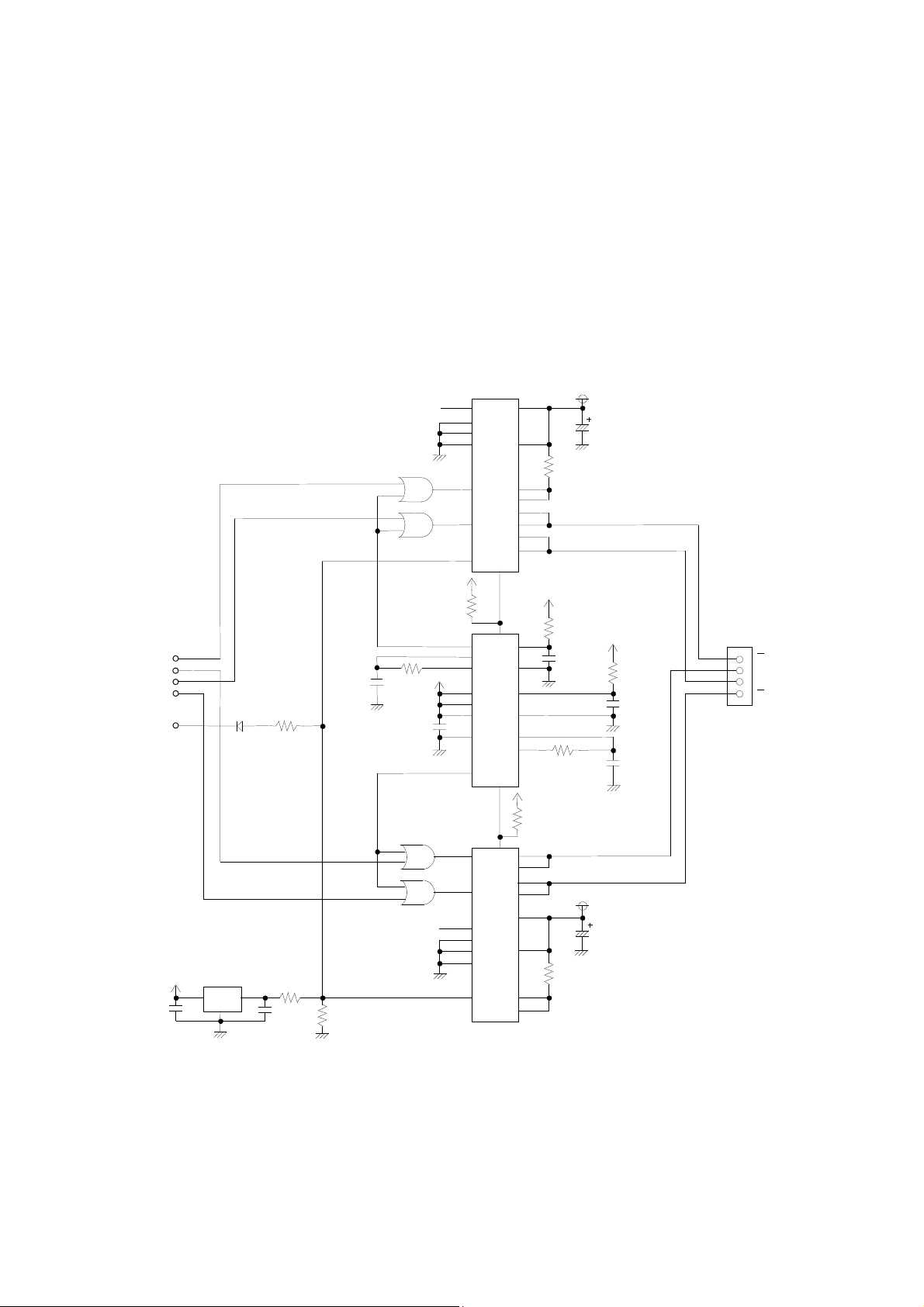
3.4.1 Motor Drive Circuit
4
1%
1%
3
11 20
16
20 11
6 1 15 14
12 12
3
19 6
Vp
18
2
12
(1) Sample Drive Circuit
Sample drive circuit for the motor are shown in Figure 3-3.
NC
9
1
13
14
LB1843V-E
10µF
0.51Ω
1%
1/2W
50V
15
5
3
74HC123A
9
LB1843V-E
19
7
6
10
Vcc
10KΩ
2
18
15
4
5
Vcc
3KΩ
1%
0.01µF
10%,10%
1KΩ
1%
0.51Ω
1%
1/2W
Vp
10µF
50V
Vcc
3KΩ
1%
0.01µF
10%,10%
0.01µF
10%,10%
6
A
7
B
8
A
9
B
PH1
PH2
PH3
PH4
CTCRL
0.1µF
Vcc
1SS294
(TE85L, F)
µPC1060C-A
1
74HC32
0.01µF
10%,10%
1.8KΩ
1%
2.7KΩ
2
0.1µF
3.3KΩ
1KΩ
1%
0.1µF
74HC32
NC
Vcc
10KΩ
Vcc
17
13
2
4
3
11
8
5
13
14
9
1
17
Figure 3-3 Sample Drive Circuit (Motor)
3-6

(2) Excitation Sequence
L
H
H
B
As shown in Table 3-4, the LTP1245 feeds paper in the normal direction when the motor is excited
in the order of step 1, step 2, step 3, step 4, step 1, step 2, . . . . On the other hand, to rotate the
motor in a reverse direction, drive the motor in the reverse order of: step 4, step 3, step 2, step 1,
step 4, step 3, . . . .
Table 3-4 Excitation Sequence
Signal Name Sequence
Step 1 Step 2 Step 3 Step 4
A Low High High Low
B High High Low Low
A High Low Low High
B Low Low High High
A
B
H
L
H
A
L
L
1 DOT LINE
Figure 3-4 Input Voltage Signals for the Sample Drive Circuit (Motor)
3-7

3.4.2 Motor Timing
H
H
PAUSE
STATE
Refer to the timing chart in Figures 3-5 and 3-6 when designing the control circuit or software for starting
and stopping the motor. Also take note of the following precautions:
Precautions for Designing the Motor Control Circuit and Software
(1) Stop step
To stop the motor, excite for a single step period with a phase that is the same as the last one in
the printing step.
(2) Pause state
In the pause state, do not excite the step motor in order to prevent the motor from heating. Even
when the step motor is not excited, it maintains a holding force to prevent paper from sliding.
(3) Start step
To restart the motor from the stop step, immediately shift the motor into the printing sequence.
To restart the motor from the pause (no excitation) state, shift the motor into the printing sequence
after outputting a phase that is the same as that of the stop step for a single step.
When using the Sample Drive Circuit (Motor) :
1 DOT LINE
PH1
L
H
PH2
L
H
PH3
L
PH4
L
STOP
STEP
START
STEP
PRINT STEP
PRINT STEP
Figure 3-5 Motor Start/Stop Timing (Sample Drive Circuit (Motor) )
3-8

(4) Others
Do not print paper at the intermittent feed mode. Doing so may deteriorate the printing quality due
to irregular paper feeding pitch.
To print characters and bit images, always follow the start step and stop step.
3-9
 Loading...