

OPERATING
LSW-27BLK
INSTRUCTIONS
MODELS
LTW-27B,
•27BK,
-27BM
SEIKO
SEWING
TOKYO•JAPAN
MACHINE
CO.,
LTD.
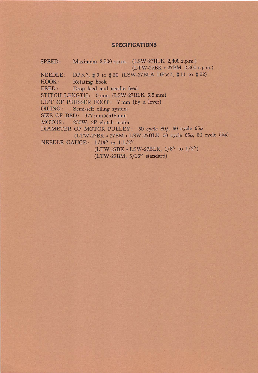
SPECIFICATIONS
SPEED:
Maximum 3,500 r.p.m. (LSW-27BLK 2,400 r.p.m.)
NEEDLE: DPX7,
HOOK:
FEED:
STITCH
LIFT
OILING:
SIZE
MOTOR:
DIAMETER
OF
OF
Rotating hook
Drop
LENGTH:
PRESSER
Semi-self oiling system
BED:
177
250W, 2P clutch motor
OF
MOTOR
(LTW-27BK•27BM•LSW-27BLK50cycle
NEEDLE
GAUGE:
(LTW-27BK . 27BM 2,800 r.p.m.)
#9to#20
feed
and
5mm
FOOT:
mmX518
1/16"
(LSW-27BLK DPX7, #11 to #22)
needle feed
(LSW-27BLK 6.5mm)
7 mm (by a lever)
mm
PULLEY:
to
1-1/2"
50 cycle
(LTW-27BK.LSW-27BLK,
(LTW-27BM,
5/16"
80^6,
standard)
60 cycle
6656,60cycle
1/8" to 1/2")
65,6
55?^)
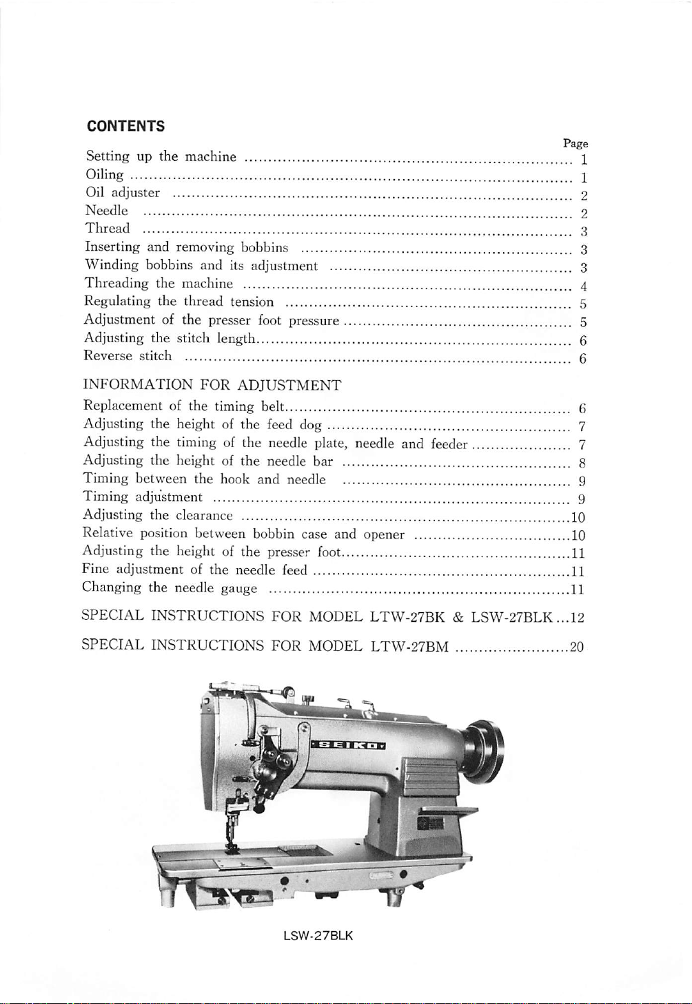
CONTENTS
Page
Setting up the machine 1
Oiling I
Oil adjuster 2
Needle 2
Thread
Inserting
Winding
Threading
Regulating
and
removing bobbins 3
bobbins
the
the
and
its adjustment 3
machine 4
thread
tension 5
Adjustment of the presser foot pressure 5
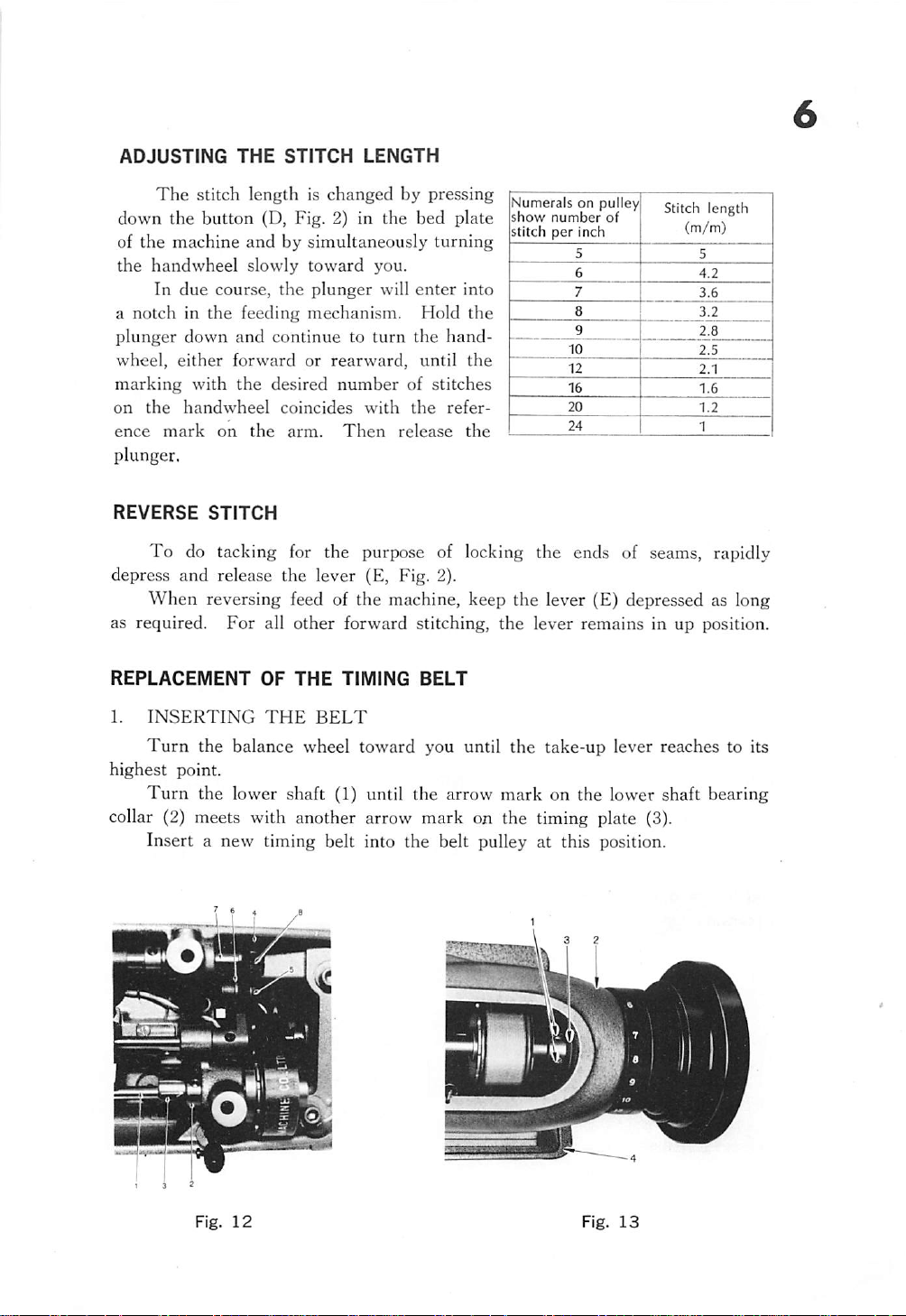
Adjusting the stitch length 6
Reverse stitch 6
3
INFORMATION
FOR
ADJUSTMENT
Replacement of the timing belt 6
Adjusting the height of the feed dog 7
Adjusting the timing of the needle plate, needle and feeder 7
Adjusting
Timing
Timing
Adjusting
the
heightofthe
between
adjustment 9
the
the hook
clearance 10
needle
and
bar
needle 9
Relative position between bobbin case and opener 10
Adjusting the height of the presser foot 11
Fine
adjustment of the needle feed 11
Changing the needle gauge 11
SPECIAL
SPECIAL
INSTRUCTIONS
INSTRUCTIONS
FOR
FOR
MODEL
MODEL
LTW-27BK
LTW-27BM
&
LSW-27BLK...12
20
8
LSW-27BLK
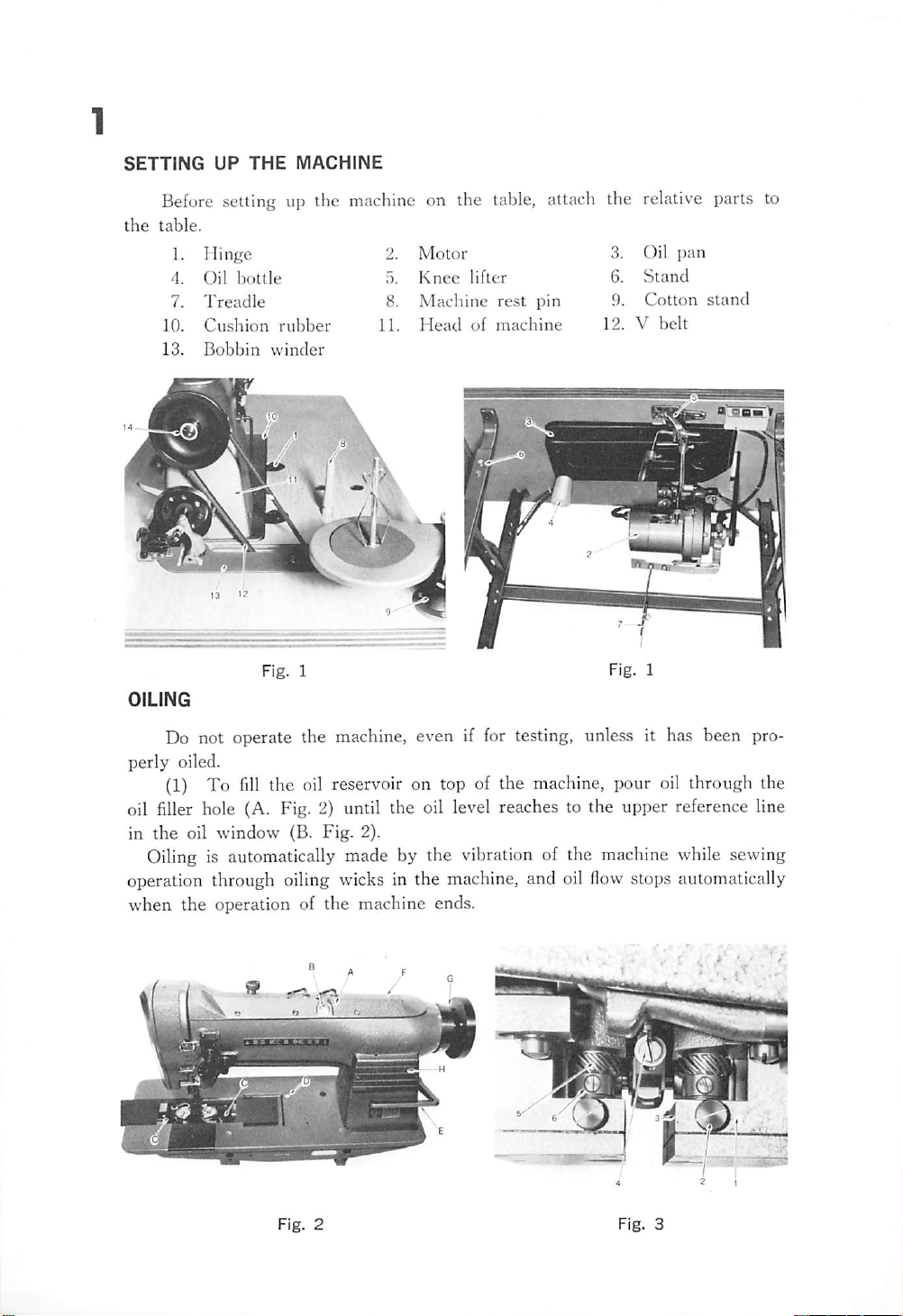
SETTING
UP
THE
MACHINE
Before setting up the machine on the table, attach the relative parts to
the
table.
1. Hinge 2. Motor 3. Oil pan
4.
Oil
7.
10.
13.
OILING
bottle
Treadle
Cushion
Bobbin
rubber
winder
Fig.
1
5.
Knee
lifter
6.
Stand
8. Machine rest pin 9. Cotton stand
11.
Head
of
machine
12. V
Fig.
belt
1
Do not operate the machine, even if for testing, unless it has been pro
perly oiled.
(1)
To
fill
oil
in
the oil reservoir on top of the
filler
hole (A. Fig. 2) until the oil level reaches to the upper reference line
the
oil
window
(B.
Fig.
2).
machine,
pour oil through the
Oiling is automatically made by the vibration of the machine while sewing
operation through oiling wicks in the machine, and oil
when the operation of the machine ends.
Fig.
2
flow
stops automatically
Fig.
3
(2)
The
hook
mechanism
the
machine.
Push open the slide-plates in the bed and pull out the oil
Fig.
2).
should
receive
careful
attention whenlubricating
gauges
(C.
Fill oil in the reservoirs for the rotating hook mechanism up to the level
marked on each oil gauge.
Care
must
be
taken
that
oil flow stops
when
oil level falls to
the
bottom.
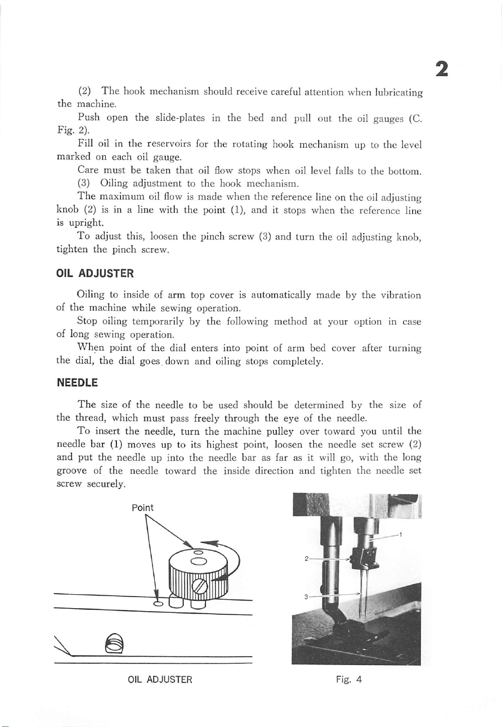
(3) Oiling adjustment to the hook mechanism.
The maximum oil
flow
is made when the reference line on the oil adjusting
knob (2) is in a line with the point (1), and it stops when the reference line
is
upright.
To adjust this, loosen the pinch screw (3) and turn the oil adjusting knob,
tighten
OIL
the
pinch screw.
ADJUSTER
Oiling to inside of arm top cover is automatically made by the vibration
of the machine while sewing operation.
Stop oiling temporarily by the following method at your option in case
of long sewing operation.
When point of the dial enters into point of arm bed cover after turning
the dial, the dial goes, down and oiling stops completely.
NEEDLE
The
size of the needle to be used should be determined by the size of
the thread, which must pass freely through the eye of the needle.
To
insert the needle,
turn
the
machine pulley over toward you until the
needle bar (1) moves up to its highest point, loosen the needle set screw (2)
and
put
the needle up into the needle bar as far as it will go, with the long
groove of the needle toward the inside direction and tighten the needle set
screw
securely.
OIL
ADJUSTER
Fig.
4
THREAD
CoUon,
synthetic or silk tliread can be used according to your purpose.
Normally left twist thread is used, but right twist thread is recommended
in the left-hand needle for perfect stitching.
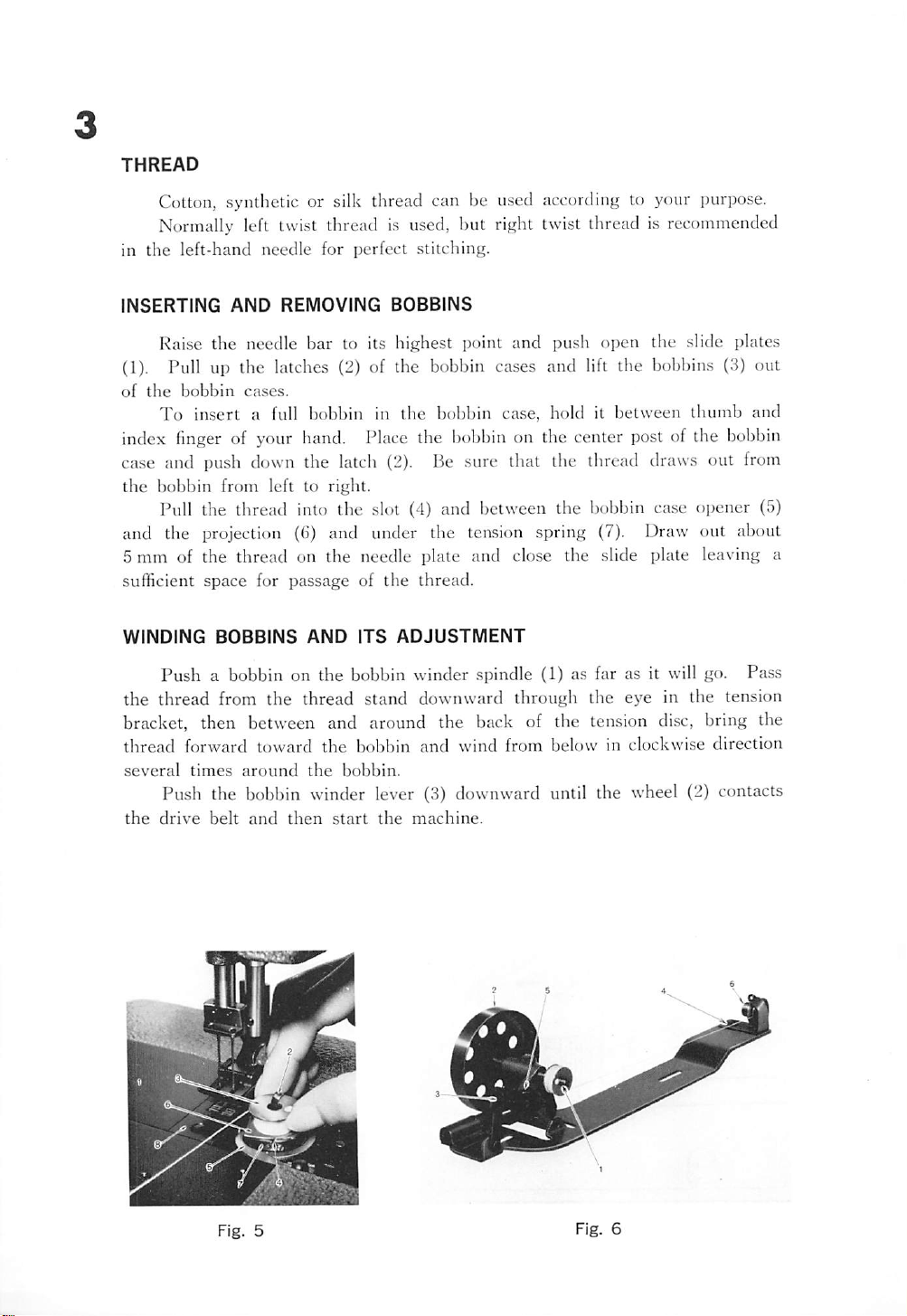
INSERTING
Raise the neetlle bar to its highest
AND
REMOVING
BOBBINS
iK)int
and push open the slide plates
(1). Pull up the latches (2) of the bobbin cases and lift the bobbins (3) out
of
the
index
bobbin
To
finger
cases.
insert
a full bobbin in
the
bobbin case, hold it between
thumb
of your hand. Place the bobbin on the center post of the bobbin
and
case and push down the latch (2). Be sure that the thread draws out from
the
bobbin
Pull the thread into the slot (4) and between the bobbin
from left to right.
ca.se
ojjener (5)
and the projection (6) and under the tension spring (7). Draw out about
5 mm of the thread on the needle plate and close the slide plate leaving a
sufficient
WINDING
space
BOBBINS
for passage of
AND
the
ITS
ADJUSTMENT
thread.
Push a bobbin on the bobbin winder spindle (1) as far as it will go. Pass
the thread from the thread stand downward through the eye in the tension
bracket, then between and around the back of the tension
thread
several
forward
times
toward
around
the
the
bobbin
bobbin.
and
wind
from
belowinclockwise
disc,
bring the
direction
Push the bobbin winder lever (3) downward until the wheel (2) contacts
the
drive
belt
and
then
start
the
machine.
Fig.
Fig.
5
6
After
the
bobbin
from the belt and winding will stop. Cut the thread and remove the bobbin
from
the
spindle.
is filled
with
thread,
release
will
cause
wheeltodisengage
Adjustment screw (5) can be turned in or out to increase or decrease the
amount
of
thread
wound
on
the
bobbin.
When fine thread is wound on bobbins, use light tension, it is regulated
by turning the knurled nut (6) on the tension bracket at the rear of the
bobbin
winder.
Bobbin can be wound while the machine is sewing.
If the thread does not wind evenly on the bobbin, loosen the screw (4)
in the tension bracket and move the bracket to right or left as may be
required, then tighten the screw.
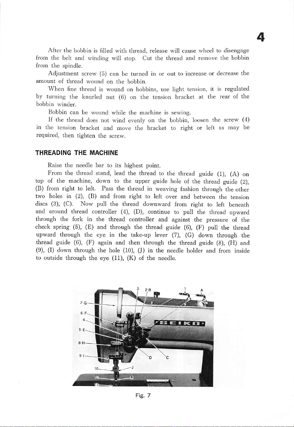
THREADING
Raise the needle bar to its highest point.
From the thread stand, lead the thread to the thread guide
top of the
(B)
from right to left. Pass the thread in weaving
two holes in (2), (B) and from right to left over and between the tension
THE
machine,
MACHINE
down
to the upper
guide
hole
of the thread
fashion
(1),
(A) on
guide
(2),
through the other
discs (3), (C). Now pull the thread downward from right to left beneath
and around thread controller (4), (D), continue to pull the thread upward
through the fork in the thread controller and against the pressure of the
check spring (5), (E) and through the thread guide (6), (F) pull the thread
upward through the eye in the take-up lever (7), (G) down through the
thread guide (6), (F) again and then through the thread guide (8), (H) and
(9), (I) down through the hole (10), (J) in the needle holder and from inside
to outside through the eye (11), (K) of the needle.
?
28
ltj
Fig.
7
REGULATING
For
ordinary stitching,
be
equal
on either thread is stronger
result.
If the tension on the upper thread is greater than
it
will be straight along
the
If
THE
so as to
tension on
THREAD
lock
the
TENSIONS
the
tension of
both
threads
than
the
upper surface of
lower
threadisgreater
the
upper
and
in
the
centerofthe
on the other, imperfect stitching will be the
that
the
fabric.
than
thatonthe
the lower thread will lie straight along the underside of
Perfect stitching
lower threads should
fabric.
If
the
tension
on the lower thread,
upper thread,
the
fabric.
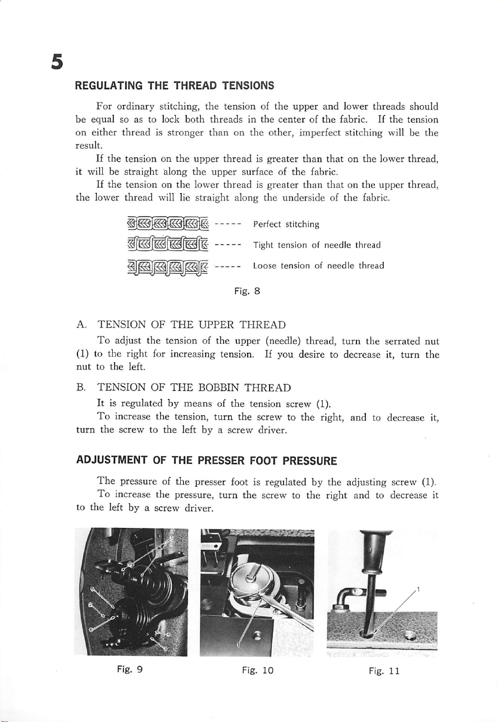
A.
Tight tension of needle
Loose
tension
Fig. 8
TENSION
To
adjust the tension of the upper (needle) thread, turn the serrated
OF
THE
UPPER
THREAD
of
needle
thread
thread
(1) to the right for increasing tension. If you desire to decrease it,
nut
to
the
left.
B.
TENSION
OF
THE
BOBBIN
THREAD
It is regulated by means of the tension screw (1).
To increase the tension, turn the screw to the right, and to decrease it,
turn
the screw to the left by a screw driver.
ADJUSTMENT
OF
THE
PRESSER
FOOT
PRESSURE
The pressure of the presser foot is regulated by the adjusting screw
To increase the pressure, turn the screw to the right and to decrease it
to
the
left
by
a screw driver.
turn
nut
the
(1).
Fig.
10
Fig.
11
ADJUSTING
The
the
down
of
the
machine
the
handwheel
In
due
a notch in
plunger
wheel,
down
either
marking
on
the
handwheel
ence
mark
plunger.
THE
STITCH
LENGTH
stitch length is changed by pressing
button
the
with
(D, Fig. 2) in the bed plate
andbysimultaneously
slowly
course,
the
toward
plunger
you.
will
feeding mechanism. Hold
and
continuetoturn
forward
the
on
the
or
desired
coincides
arm.
rearward,
number
with
Then
enter
the
until
of
the
release
turning
into
the
hand-
the
stitches
refer
the
Numerals on pulley
show
stitch
number
per
of
inch
Stitch length
(m/m)
REVERSE
To
depress
When
as required.
REPLACEMENT
1.
INSERTING
Turn
highest
Turn
STITCH
do tacking for the purpose of locking the ends of seams, rapidly
and
release the lever (E, Fig. 2).
reversing feed of the machine, keep the lever (E) depressed as long
For
all other forward stitching, the lever remains in up position.
OF
THE
THE
the
balance wheel
TIMING
BELT
toward
BELT
you until
the
take-up
lever reaches to its
point.
the lower shaft (1) until the arrow mark on the lower shaft bearing
collar (2) meets with another arrow mark on the timing plate (3).
Insert a new timing belt into the belt pulley at this position.
I

2.
REMOVING
THE
TIMING
BELT
Remove the arm top cover (F, Fig. 2) and remove the timing belt from
the
belt pulley, loosen
Loosen
the two set screws (G, Fig. 2) for the handwheel and remove the
the
collar
set
screws (1, Fig. 13).
handwheel adjusting screw (14, Fig. 1), draw out the handwheel from the
arm
shaft.
Loosen
rear bushing (3, Fig. 13) from the arm hole.
In case of the machine with reverse stitch mechanism,
lever (E, Fig. 2) with its shaft.
the arm shaft rear bushing set screw (2, Fig.
draw
13),
pull out the
out the reverse
Removing or inserting the timing belt is made through the hole drawn out
the rear bushing.
After inserting the belt correctly, replace the rear bushing, screws, the arm
top
cover,
mentioned
etc. to their
in
the
item
original
No.
places.
1.
Finally,
adjust
the
timing
marks
ADJUSTING
The
plate
(2) is normally 1 mm.
To
the
feed dog to its highest point.
THE
HEIGHT
maximum height of the feed dog (1) from the surface of the needle
adjust this height, tilt
OF
THE
the
FEED
machine,
DOG
turn
the
handwheel
so as to raise
Loosen the set screw (4, Fig. 3) and raise or lower the feed dog as may
be
required.
Securely tighten the set screw.
ADJUSTING THE
1.
THE
POSITION
Adjust
Set the
equal
the
screw.
position
before
the
starting
feed
of the
TIMING
OF
motion
feeder
feed
motion
OF THE
THE
FEEDER
to the
so that both
NEEDLE
maximum
and
after
PLATE,
AGAINST
and
loosen
clearances
finishing
NEEDLE&FEEDER
THE
NEEDLE
the
screw
A and B
the
feed.
(Fig.
Securely
(4,
PLATE
Fig.
12).
15)
are
tighten
r
Fig.
14
1
mm
Fig.
15

2.
THE
POSITION
FEEDER
To adjust this, turn the handwheel to raise the needle
point
and
put
correct
OF
THE
needles.
NEEDLE
AND
NEEDLE
HOLE
bar
to its highest
OF
THE
Turning the hand wheel to lower slowly the needle bar, check whether
the
needle
If
plate (H, Fig. 2) and loosen
the
arm.
the
descends
needle
does
to
the
not
center
enter
of
the
needle
into
the
the
screw (1, Fig. 16) through the window of
hole
centerofthe
of
the
hole,
feeder
remove
or
not.
the
side
Holding the bottom of the needle bar rock frame (I, Fig. 17), move it as
may be required to get the correct position to the center of the needle hole
of
the
feeder.
Then,
tighten
the
screw
and
replace
the
side plate.
ADJUSTING
1.
When
between
eyeis22.2
To
of the needle
correct position.
THE
HEIGHT
the
the
mm.
needle
surface of
bar
adjust this, loosen
bar
and the needle
After
this, tighten
OF
THE
NEEDLE
BAR
is at its highest point, normally
the
needle plate
the
screw (2, Fig. 17)
bar
the
and
the
upper
and
move
connecting stud (3, Fig. 17) to get the
set screw.
the
measurement
end
of
the
the
setting position
2. There, is another method for this adjustment by setting the needle
to its
lowest
point.
The normal position, in this case, is 4.1 mm approximately from the hook
pointtothe
NOTE:
upper
These measurements are approximate standard, accordingly, following final adjustments
are
recommended.
endofthe
needle
eye.
needle
bar
Bb
Fig.
Fig.
16
17

TIMING
Set the stitch length to 0, turn the balance wheel to lower the needle bar to
its lowest point turn the wheel toward you, and when the needle raises 2.1 mm
from the lowest point of its travel, normally the hook point is at the center
of the
end of the needle eye should be 2 mm, further the clearance between the
hook
BETWEEN
After setting the needle bar height as stated 1. or 2., confirm as under.
needle,
point
and
If they are not measured as above, adjustments are made as follows:
and
the
THE
the
measurement
needle
2.1mm
HOOK
hollow
AND
should
Fig.
NEEDLE
between
be
0.05
18
the
hook
to 0.2
point
mm.
and
the
upper
TIMING
Loosen
gear
(2,
two
set
Loosen
the
proper
For
model
Loosen
to
rightorleft
ADJUSTMENT
the
two
set
Fig,
screws
19A)
securely.
to the
screws
center
{1,
Fig.
of the
19A),
small
set
gear
the
(5,
the screw (6, Fig. 3) on the small gear, move the
timing.
LSW-27BLK
the
two
and
Then,
set
set
the
tighten
screws
proper
the
screws
(1)—Fig.
timing.
securely.
19A—,
Then,
move
tighten
positionofthe
Fig.3)and
hook
the
large
drive
the
screws
tighten
and set
gear
securely.
large
the
(2)
Fig.
19A

For
model
Loosen the three set screws (1)—Fig.
proper timing. Then, tighten the screws securely.
LTW-27BK
Fig.
19B—,
19B
10
move the hook and set the
ADJUSTING
Loosen
the
rightorleft
to use perfect needles.
RELATIVE POSITION BETWEEN
Loosen
THE
CLEARANCE
the set screw (3, Fig. 3) and
to get the
the
screw
(1),
correct
turn the
clearance
BOBBIN
balance
(4),
move
and
CASE AND OPENER
wheel
the hook
tighten
until the
the
saddle
screw.
opener
located at the extreme right hand position of its travel.
In
this
position,
adjust
it so that the
clearance
between
the
inside
the opener and the tab on the bobbin case holder is about 0.2mm.
After the adjustment, tighten the screw securely.
(5) to
Be
edge
sure
(2)
is
of
Fig.
20

11
ADJUSTING THE HEIGHT OF THE PRESSER FOOT
Loosen
lifter and loosen the screw (4, Fig. 17).
Move
screws securely.
FINE ADJUSTMENT OF THE NEEDLE FEED
Ordinarily,
the
needle
If,
of
the
ments
Loosen
rock
shaft
momentum. Tighten the nut
CHANGING
Remove
in this order.
pair
of pliers.
Put the desired needle clamp in place by screwing it tight into the needle
bar.
Loosen the needle bar connecting stud screw (2, Fig. 17) and turn the
needle bar to correct the direction of the needle clamp.
Set the correct timing between the hook and the needle.
Put the feeder, needle plate and presser foot in this order securely.
sufficiently the adjusting screw (1, Fig.
the
when
needle
are
offered.
(7,
presser
the
feed.
the
feed
the nut
Fig.
THE
the
The
foot
up or
feed
motion
motion
does
accordingtothe
(5,
Fig,
12)
12)
for
more
NEEDLE
needle,
needle clamp is a screwed type that is removed with a
GAUGE
presser
down
of the
not
synchronize,orincreasingordecreasing
sewing
and
bring
feed
momentumorkeep
firmly.
foot,
needle
as may be
lower
feed
conditions,
(6,
Fig.
clamp,
11),
raise the presser bar
required,
and
synchronizes
the
following
12)
close
to the
away
needle
plate and feed dog
tighten
with
feed
from
the
that of
that
adjust
driving
for
less

12
SPECIAL
INSTRRCTIONS
FOR
MODEL
LTW-27BK
AND
LSW-27BLK
Models LTW-27BK and LSW-27BLK are specially designed as two-needle
angular seam sewing machines. Model LTW-27BK employs standard size
bobbins, while model LSWr27BLK uses large-capacity bobbins. Both models
are equipped with devices to prevent the presence of lower thread loops when
sewing seams with acute (less
NEEDLE BAR
Pushing the
"L"
or
oneofthe
"R"
two
STOP
needle
will
selectively
individual
MECHANISM
bar
change
needle
than
90°) andles.
over
suspend
bars.
lever
the
reciprocating
(1)—Fig.
21—to
movement
either
position
of either
Basically, there are two functions to this mechanism, one which causes the
needle bars to operate and stop, and the other which switches from one needle
bar
to
the
other.
Fig,
21

13
A) NEEDLE BAR STOPPING AND OPERATING MECHANISM
The
two needle bars individually and jointly, with the components as
sembled to their
22) to accomplish the stopping and the operation.
The
positioning
needle
inserted
the
bar
into
set screws of
insides,
connecting
grooves
the
cooperate with the needle bar connecting stud (Fig.
of the
(1)
needle
needle
stud is
done
bar at their
by
meansofsplit
near the top ends of the
bar
position guides.
upper
needle
ends
stop
bars, as
rings
relative
(2)
wellaswith
At their opposite ends the needle bars are locked to the needle bar con
necting
a
sequently, when
needle
what
stud by
mechanism
means
inside
positioned
of three
the
needle
as
bars move up and down with the
may
best be described as
special
bars
described
"operational".
high-strength
beyond
above
steel
balls
expanded
the diameters of the bars. Con
and as pictured on Fig.
needle
bar connecting stud and are,
Needle
to the
which
22,
are
by
the
0.
Needle
bar
connecting
stud
Fig.
Needle
22
bar
Fig.
23A
Operating mode Non-operating mode
Fig.
23B

The
mechanism
disposed
within
the
needle
bar is
detailedonFig.
23A
which shows a needle bar in the operational state, while Fig. 23B shows a
needle
adjusting
bar in
nut
stopped
(3)
against
position.
cone
The
forceofspring
(4)
which
in turn
(1)
forces
pushes
three
plunger
steel
(2)
balls
and
(5)
outwardly beyond the diameter of the needle bar and against the countersink
at the bottom end of the needle bar connecting stud (6). At the same time
triangular prism (18) is allowing three steel balls (7) to recede below the dia
meter
connecting
21) into
selector block
rod end of the reciprocating
of
When
the
needle bar. Consequently,
stud
will cause
the
stoppinganeedle
either
the
"L"
(8)—Fig.
or
23B—directly above the respective rod end (9). This
bar by
"R"
needle
the
movement
needle
bar
moving
positions,
to reciprocate.
the
change
the
mechanism
bar nowcontacts the selector
of
the
needle
over lever (1)
locates
needle
block
causing
bar
(Fig.
bar
the rod to move downward inside the needle bar causing cams (10 and 11) to
likewise move downward. This allows upper balls (19A) to recede below the
diameter of the needle bar while at the same time forcing lower balls (19B)
outwardly beyond the diameter of the needle bars. Lower balls (19B) are now
forced against the tapered mouth (14) of the needle bar bushing (13) and will
stop the downward movement of the needle bar. While needle bar position
guide (15) contacts the bottom of the upper end of the needle bar rock frame,
thereby locking the needle
upper balls
(1*9A)
do no longer lock the needle
bar
tightly into place.
At
the same time the retracted
bar
against the underside of
the needle bar connecting stud (6) and so allow the latter to glide along the
needle
bar.
14
PREVENTION
Needle bar position guide (1) in conjunction with
position bracket (3), attached to needle bar connecting stud (2)—Fig. 24—in
conjunction with needle bar position guide plate (4) keep the needle
rotating. In the operating mode, bracket (3) serves this purpose, while
a needle
rotation.
OF
NEEDLE
bar
is stopped the channels embossed into the guide plate (4) prevent
BAR
ROTATION
the
bifurcated needle
bar
bar
from
when
n
Fig.
24

15
VERTICAL ADJUSTMENT OF NEEDLE BAR POSITION
The
trouble-free
are
fixed
making
bushing
the
(5)—Fig.
exact
within the needle bar rock frame
vertical
engagement
required
fine
24—is
position
and
adjustment
of the
disengagement,
of the
providedinneedle
needle
respectively,
(20)—Fig.
needle
bar
bars is
23.
bar
position,
connecting
important
since
their
for
their
positions
For the purpose of
and
eccentric
link
(6).
B) NEEDLE BAR RELEASE MECHANISM
When
or
"R"
its highest position, will contact the underside of selector block (8) causing
said needle
the
needle
position, the rod
bar
bar
to become disengaged from its driving mechanism.
change over lever (1)—Fig. 21—is set to either
end
(9) of
the
selected needle bar, when
same
"L"
is in
OPERATION
Shifting
the needle
The
and
was disengaged, is fixed to their normal position as Fig. 25B.
same
time, the needle
When
the
21—,
connection
stop separates from
position.
Then,
its highest position
OF
THE
NEEDLE
the
needle
bar
change over frame to move in direction of the arrow (Fig. 25).
needle
bar
disengaing
needle
bar
returntotheir
the
needle
bar
change over frame connection, when
bar
stops when same reached in its
the
needle
change over frame and
first position.
the
needle
bar
connecting
and
becomes normal
BAR
change
bar
bar
CHANGE
over
lever—Fig. 21—to
stop pushing the lever release (4)—Fig.
Thereby,
stopping
stud
incorporates with the needle
twin
OVER
the
needle
stud
needle operation.
FRAME
the
next
bar
the
slide block for needle
and returns to
"R"
will cause
needle
change over frame
bar
lowers
At
the
highest position.
their
first
bar
in
W
Fig.
25

SPECIALLY-DESIGNED ROTATING HOOKS FOR ANGULAR
SEAM
developed
ances
Furthermore, the
for
when
thread
The horn-like extension (4) of the
taking up the slack, while it courses around the hook.
SEWING
The
rotating hooks for models LTW-27BK and LSW-27BLK have been
specifically
(1)—Fig.
much
increased
Also,
should
the
upper
guard
(2)
The cap-type
26—to
hook
thread
the
(needle)
will
design
for these
allow
for
machine
the
model
volume.
machines
most
LSW-27BLK
and are
effective
be stopped at that point of its stitching cycle
thread is about to
allow
unhampered
passage
of the bobbin case assures
hook
gib retains the upper thread temporarily
provided
transit of the
with
its
pass
over the
of the
larger
thread.
smooth
with
sewing
bobbin
hook,
thread handling.
specific
thread.
provides
the shape of
Thus looping is prevented, particularly when heavy threads or those lacking
smoothness are employed.
Automatic lubrication of the moving parts of the hooks
allows
the main
tenance of adequate sewing speeds without sacrificing their useful service
16
clear
life.
Fig.
26
METHOD
OF
PREVENTING
LOOPINGOFTHE
LOWER
(BOBBIN)
THREAD
When sewing angular seams—particularly acute angles—with machines
fitted
with
conventional
Bobbin
types
of rotary
Fig.
hooks,
20
mm
27
the
appearanceoflarge
KIO-H
mm
T,
B
• ^
loops
of

17
the lower thread
by the transport of the
needle
with
by means of springs any
bar
The
devices
Fig.
rotary
27A
LSW-27BLK.
to
pick
up any
the dotted outline of the thread take-up spring
rest
position
figure,
guide hole in retainer (2).
out
of spring (1) is such
(25/32'')
THREAD
each of the two upper (needle) threads—installed in the machines.
spring
When
from
of
There
under
CONTROLLER
can
be noticed at
material
is
at
rest.
hooksofmodels
which
shows
Fig.
prevent the
excess
the
methodofthreading
27B
shows
excessofthread
prior to
(1)
in this position,
thread
are
pulling
travelsadistancetowhere
bobbin case tension spring (3).
that
can
be absorbed.
SPRINGS
two separate
around
looping
of thread.
the
back
further
slack
and
LTW-27BK
for
individual
the
underside of the work.
the
sewn
corner,
and
of the
lower
of the
position
the
excess
of thread take-up
preventionofloops.
(lA)
thread.
its eye
demand
thread
for bobbin
The
loop containing as
thread
This
while
the one
LSW-27BLK
thread by withdrawing
bobbin
caseofmodel
spring
Also
which shows same in a
As can be seen
coincides
function
controller springs—one for
with
threadisthen
and
much
is caused
raised
are
equipped
(1)
ready
note
froni
the
thread
pulled
effectiveness
as 20 mm
that
this
Rg.
28
When sewing angular seams with either one of the two needle bars
stopped, upper thread is not drawn out at an equal rate for both needle bars.
Consequently,
condition.
A)
Adjusting
Loosen
for
more
(2).
two
thread
controller
springs
are
These springs can be adjusted individually.
the rear thread controller
set
screw
action;for
(2),
less
turn
action
thread
turn
spring
controller
stop
(3)
to the
required
spring
left
stop
and
to
(3)
tighten
cope
to the
with
set
right
screw
this

B) Adjusting the front thread controller spring
Loosen set screw (11) and turn spring stop (10) to the left to increase
the
action
of this
of thread take-up spring (7) and to the right to reduce the
spring.
After the
desired
setting of the spring has been
established,
tighten set screw (11).
C) Adjusting
I. Slightly
II. To adjust the
driver into the slot of the take-up spring slot
take-up
loosen
spring
tension
nut (4) and also set screw
tension
of the rear thread take-up spring (1)
(5).
placeascrew
(6)
and turn to the left
to tighten the spring tension and to the right to loosen same. After
the
desired
III. To adjust the
tension
tension
has been
determined,
tighten set
of the front thread take-up spring
screw
(7),
(5).
set screws (9) in collar (8) turning same to the left to tighten and to the
right to loosen it. Upon determining the desired tension of this spring,
tighten set screws (9) and also nut (4).
loosen
18
action
two
ADJUSTING
I.
Set
II.
Turn
its
travel.
4.1mm
4.4
in
LTW-27B
mminLSW-27BLK
THE
HEIGTH
stitch
lengthtoshortest
OF
THE
stitch.
NEEDLE
CLAMPS
handwheel until needle bar has descended to the lowest point of
2
mm
Fig.
29
Fig.
30

19
III.
Turn
hook
IV.
onlysothat
To
correctly adjust the position of
hook
point
the
comestothe
needle
as (7)—Fig. 29.
needles (1) relative to hook points
(2), remove the needle clamps (3) from their respective needle bars by
removing needle clamp
needle clamp adjusting screw (5) become accessible.
set
screw
(4).
Upon
removing
the
needle clamps,
Turn
screw (5) either in or out to obtain the 4.4 mm (11/64") in LSW-27BLK
(4.1mm (5/32") in LTW-27BK) distance between the eye of the needle
when at its lowest position and
clamps with needles have been replaced on
V.
Be sure
of needle
Turn
hand
that
needle clamp adjusting screw (5) contacts
bar
plug (6) and tighten needle clamp set screws (4).
wheel toward you allowing needles to rise.
hook point crosses the centerline of the rising needle, it should be 2 mm
(5/64")
above the upper end of
necessary. (Fig. 30)
the
hook point (Fig. 29) after the needle
the
needle bars.
When
the
eye of
the
needle. Adjust if
adjusting
the
the
rotating
bottom
TIMING
ADJUSTMENT
Turning
the
OF
THE
hand
wheel, confirm whether
LOWER
STEEL
the
BALL
needle
bar
motion is not
smooth due to projection of the lower steel ball (2)—Fig. 31—out of the out
bar
side diameter of the needle
(3).
Normally, when the lever is changed over and the needle stop stud (1)
is pushed, those parts in the needle
bar
begin to operate at the same time
and the needle bar stops at its highest point.
Confirm in this position whether there is not a excess play on the needle
bar
in
vertical
direction.
This adjustment is made by the steel ball guide (4) and its nut (5), and
the
standard
dimention
is
30.5
mm
30.5mm
Fig.
31

20
SPECIAL
ASSEMBLING
INSTRUCTIONS
THE
KNIFE
FOR
CHANGE
MODEL
OVER
LTW-27BM
PEDAL
1. Connect the knife chantre over lever {1, Fig. 32), the pedal (1, Fig.
33)
and
the
chain
(2, Fig. 33).
The
proper position of the pedal is about at an angle of 20°.
2.
of
the
Attach
table
the
knife
releasing
.so
that the hole (3, Fig. 32) of the lever (2, Fig. 32)
rod
bracket
(3, Fig. 33) on
the
and
underside
the
hole
{5, Fig. 33) of the releasing rod (4, I'ig. 33) assembled to the releasing rod
bracket
(3, Fig. 33) are on a vertical line.
A.ssemble the releasing rod to be j)arallel with the knee lifter connecting
rod
(0, Fig. 33).
At
the
same time, adjust the length of the chain so that
the
releasing rod
is parallel with the underside surface of the table.
3.
Set
the
pedal
extension
rod (9, Fig. 33)
with
the
screw (8, Fig. 33) to
the pedal and attach the pedal extension rod (10, Fig. 33) to the releasing rod
atalittle
to
the
left
fr{)m
the
center
of
it.
Care
must
be
taken
.so
that
the
pedal extension rod can move slightly.
4. Adjust so that there is no slack on the chain attached to the front of
the
pedal, and connect the two pedal extension rods with
(11, Fig. 33).
the
adjusting screw
Fig.
Fig.
32
33

21
KNIFE
to
REPLACEMENT
1. To
(2) to
2. To replace a new knife,
lowest
that the
of the
CHANGE
The
operation and stopping of the knife
To
operate the knife, pedal the treadle toward A direction (Fig. 34), and
stopittoward
remove
remove
position.
clearance
knife
Securely tighten the two screws.
OVER
B direction.
OF
the
knife,
it.
Then, put the
between
(2)
is 1
mm
OPERATION
THE
loosen
as the illustration on the
KNIFE
the two
turn
the handwheel until the knife lowers to its
knife
the
surfaceofthe
Fig.
like
34
screws
the
are
made by pedaling.
\
(1) and pull
figure
needle
35,
plate
figure.
but
(3)
down
adjust
and
the
them
the
knife
so
edge
J
1mm
Fig.
35

ADJUSTING THE KNIFE POSITION {right and left directions)
22
Loosen
the
right
needle
ADJUSTING
(up or down direction)
1. When fitting the knife oscillating crank, adjust the oscillating shaft (2,
Fig. 36) so that the right end of the shaft comes out about 1mm
oscillating crank (1, Fig. 36),
an equal distance starting from the horizontal line (A, Fig. 37).
Then
2. When fitting the stop collar, adjust the clearance between tlie end of the
pin (1, Fig. 37) and the groove on the part (2, Fig. 37) is 0.5mm, and in this
position, set the stop collar (4, Fig. 36) closely to the oscillating shaft (2, Fig.
36), then tighten the collar set screw (5, Fig. 36).
or
plate.
the two
left
THE
tighten
screws
(4, Fig. 35), adjust the knife holder (5,
so that the
KNIFE
the
CHANGE
screw (3, Fig. 36)-
knife
lowers
also,
adjust the crank to actuate up or down at
OVER
to the
POSITION
center
of
the
Fig.
groove
from
35) to
of the
the
mm
Fig.
36
Fig.
37

23
TIMMING
Normally, when the needle is at its lowest point, liie knife should be at
its highest point or vice versa.
This is due to the
is
fed,
To
of the
Then, tighten the cam set screws.
BETWEEN
anditcuts
time
this,
cam
(2)
THE
NEEDLE AND KNIFE
reason
the
material
loosen
the
fasterorslower
; f
rv
that the
after
two
set
as may be
knife
the
screws
does
feeding
(1),
required.
not
operate
motion.
adjust
the
while
rotating
the
material
position
Fig.
38

 Loading...