

Page 1

OPERATING
INSTRUCTIONS
FOR
LSC-8BV-1.8BLV-1
LSC-8B-I.8BL-1
LSC-8BH-I.8BLH-I
as
E ( K
II
LSC-8BV-1
LSC-8B-1
SEIKO
SEWING
TOKYO•JAPAN
MACHINE
CO.,
LTD.
Page 2

INSTRUCTIONS
This
is a
under
FOR
SEIKO
guidetouseofSEIKO
the
best
condition.
MODEL
LSC
model
TYPE
LSC
INDUSTRIAL
type
industrial
SEWING
sewing
MACHINES
machines
SEIKO
LSC series are a single needle, lock-stitching, needle,
feed, reverse feed, semi-automatic lubrication
machine.
Please read
this
guide
thoroughlysothat
Specifications
Model
Speed
(s.p.m.)
Needle
Hook
Stitch
Length (Max.) 6
Presser
Foot
Presser Lift
Moving
Presser
Up/Down
Amount
Lift
LSC-8BV-1
2,500
DPx
17
Standard
Rotary
Standard
mm
^16
LSC-8BLV-1
2,200
Standard
Large
7
mm
#16
you
LSC-8B-1
2,300
Standard
Standard
6
system,
may
#18
mm
Alternating
3 — 6
8mm(by
expect
LSC-8BL-1
Standard
pressers
mm
lever)
cylinder
2,200
#18
Large
7
mm
upper&lower
bed sewing
good
performance.
LSC-8BH-1
2,500
Standard
#16
Standard
6
mm
LSC-8BLH-1
2,200
Standard
Large
7
mm
#16
Needle
Bar
Stroke
Thread
Take
Up
Thread
TakeUpStroke
Diameter of Cylinder Bed
Working
Space
Weight
Motor
Thread
57.5
46
mm
mm
67
mm
50
mm
Slide
57.5
mm
46
mm
258mmx
29kg(with
250
W •2PClutch
33.2
mm
motion
110
Synthetic
type
base)
67
50
mm
Motor
mm
mm
57.5
46
mm
mm
Use: All kinds of work In the clothing, footwear, upholstery, leather industry such as shoes, canvas
products, dress shields, sleeve, sandals, gloves, sports goods, especially. Model LSC-8BV-1 &
LSC-8BLV-1
able
without
are suitable for various kinds of tape stitching with a edge binder which is interchange
having any
alternationtoany
other
parts.
67
mm
50
mm
Page 3

—
INDEX
CONTENTS
Page
Setting up
Oiling 2 —3
Oil
adjustment
Needle
Thread
Winding
Adjustment
Inserting and removing
Threading
Regulating
Regulating
the
machine 2
bobbin
of
the
bobbin
the
machine
the
thread
the
pressureongoods 8
winder
the
bobbin
tension 7
Adjusting the stitch length and reverse stitch 9
Adjusting the liftofthe alternating presser feet 9
Instructions
for
LSC-8BV-1
and
8BLV-1
1
3
4
4
5
5
6
7
10
INFORMATION
Adjusting
Adjusting
Adjusting
the
the
the
Timing between
FOR
ADJUSTMENT
heightofthe
timingofthe
heightofthe
the
needle and the hook 13
feed dog 11
needle plate, needle and feeder 11 —12
needle
bar
12
Timing between the needle and the feeder 14
Adjusting the heightofthe
presser feet
14—15
Timingofthe vibrating presser foot 15
the
Adjusting
thread controller spring 16
Page 4

SETTING UP THE MACHINE (Fig. 1)
»
to
Before
the
table.
setting
up
the
machine
on
(1) Stand (2) Motor
(4) Cotton stand (5) Tape stand (only
(7) Knee lifter
8BLV-1)
and Machine base
(9) V shape belt (10) Bobbin winder
the
table,
LSC-8BV-1,
attach
the
relative
parts
(3) Treadle
(6) Machinehead
(8) Chain
if
Fig. 1
OILING AND ITS
* Do
perly
oil filler hole (A), until oil level
♦
ing
automatically
not
oiled.
To
fill
Oilingisautomatically
operation
ADJUSTMENT
operate
the
oil
through
when
the
machine,
reservoir
the
the
operation
(Fig.
eveniffor
on
the
reachestothe
madebythe
oiling
wicksinthe
of
2)
topofthe
vibrationofthe
the
machine
testing,
machine,
upper
machine,
ends.
unlessithas
pour
oil
reference
machine
and
oil flow
been
through
line (B).
while
pro
the
sew
stops
Page 5

» When
without using
(B),
and oil sufficiently to respective necessary
ion
and
starting
try
pre-running.
the machine initially and
at
all,
make
sure the oil volume through oil level indicator
after
parts
kept
away for a long time
before
starting
operat
OIL
ADJUSTMENT
><•
While operatingthe machine, the lubrications to each spot of the machine
are
made.
When
at your option. In
the
machine
that
is in
continuous
operation,
stop
oiling
forawhile
case, turn the dial until two points fit together as
per the following picture, then the dial comes down and the lubrications
are
stopped
perfectly.
OIL
ADJUSTER
Page 6

NEEDLE {Fig.3)
*
The
size of the needle to be used should be
the
thread,
HOW
1.
Turn
uptoit's
which
TO
the
machine
highest
must
ATTACH
point.
2. Loosen the needle
bar
as deeply as it will go,
3.
Tighten
THREAD
the
needle
pass
THE
pulley
set
screw
with
set
screw
freely
NEEDLE
over
the
through
toward
(2)
and
you
put
long groove of
securely.
determined
the
eyeofthe
until
the
needle
the
needle (3) up into
the
needle faces
by
needle.
bar
the
the
(1)
the
size of
moves
needle
left.
* Cotton, synthetic or silk
the
thicknessofthreadisupto#8
* Always use left
right
or
left
twisted
twisted
thread
thread
thread
for
can
be used according to your purpose,
for upper thread, but you
lower
thread.
can
use
either
Page 7

WINDING
THE
LOWER THREAD ON
THE
BOBBIN
(Fig.
4)
Pushabobbin
1.
Pass
2.
in
the
tension
disc.
3.
Bring
clock-wise
4.
Push
belt
(9, Fig. 1) will
5.
The
after
the
THE
ABOVE
ADJUSTMENT
*
IN
CASE
If
the
in
the
tension
required,
*
WINDING
Adjustment
the
amount
*
WINDING
Strengthofthe
on
the
thread
from
bracket,
the
thread
direction
the
lever
several
(3)
engage
pulley (2) will
bobbin
thread
is
filled
OPERATION
OF
UNEVEN
does
bracket
then
tighten
AMOUNT
screw
of
thread
STRENGTH
winding
the
bobbin
the
thread
then
between
forward
times
toward
and
automatically
with
thread.
CAN
OF
THE
WINDING
not
wind
and
move
the
screw.
OF
(5)
can
be
wound
on
can
winder
stand
and
toward
around
the
other
then
start
BE
DONE
BOBBIN
evenly
the
bracket
THREAD
turned
the
bobbin.
be adjusted
spindle
around
the
bobbin
the
side
the
be
free
WHILE
WINDER
on
in
(1)asfar
downward
the
and
bobbin.
so
that
machine.
from
SEWING.
(Fig.
the
bobbin,
to
the
or
outtoincrease
with
nut
as
it will go.
through
back
wind from
the
the
belt
4)
loosen
of
pulley
the
the
the
and
eye
tension
below
(2)
and
stopped
screw
rightorleftasmay
or
decrease
(6).
(7)
in
V
(4)
be
Fig. 4
Page 8

INSERTING AND REMOVING BOBBIN (Fig. 5
Raise
the
1.
Fig.
3)
Pullupthe
2.
3.
To
insert
about5cm,
4.
Lead
and
under
*
THREAD
bobbin
5.
keeping
into
6.
case.
Draw
the
the
hookasdeeply
Close
needle
a full
and
the
endofthread
the
tension
WINDING
Check
out
about5cmofthe
slotofthe
the
end
latch
insert
cover,
bartoits
(1,
Fig.5)and
bobbin
the
spring
the
thread
bobbin
as
but
highest
draw
(Fig. 6),
bobbin
pulled
(1,
holditpulling
into
out
Fig.6)and
DIRECTION
winding
endofthread,
case
faces
it'will
leave
go,
sufficient
point.
out
the
bobbin
through
when
directionasshown
upper
and
push
and
Draw
the
then
space
6)
bobbin
out
case.
the
slotofthe
the
fitting
pull
side.
down
for
out
the
end
from
the
endofthread
bobbin
thread
the
guide.
bobbin
Fig.
up
the
latch
And
fit
the
the
latch
passageofthe
cover
the
bobbin
into
No.
6.
(1, Fig. 5)
bobbin
securely.
thread.
(6,
by
case,
the
case
4'5
Page 9

THREADING
THE
MACHINE (Fig. 7)
1. Raise the needle
thread
top of the machine arm, down to the upper guide hole of the thread guide
(2)
two
(3).
thread
the
guide
down through the
(8),
stand
From
from right to left.
holes in (2)
Now pull the thread downward from right to left beneath and around
thread
(6),
(9) and
the
the
thread
controller
controller
pull the thread upward through the eye in the take-up lever
(10),
I t
7—4—^1
• '.0-1%
® ed up by
®rii
1
iJ-JB**/
9—12
bartoits
following
stand,
Pass
and
from
(4),
continue to pull the thread upward through the fork in
and
thread
and from left to right through the eye of the needle.
DETQcrmii
El=•=1
^
highest point
order:
lead
the
the
thread
righttoleft
against
guide
the
(6)
again and then through the
i ^
i--
ifri'i
and
lead
the
thread
thread
in weaving fashion through the
check
to
the
over
and
between
spring
2.
After
hold
the
your
pulley
that
bobbin
put their ends of
other
the
presser
operation.
thread
(5)and
the
endofthread
left
hand,
with
your
thread
needle
side
bed
foot
guide (1) on
the
tension discs
through
above
thread
and
the
threading,
turn
right
maybepick-
thread.
thread
through
for
starting
from
other
thread
guide
with
the
hand
And
on the
under
the
the
(7)
so
Fig. 7
REGULATING
* For ordinary stitching, the tension of the upper and lower threads should
THE
THREAD
TENSIONS
be equal so as to lock both threads in the center of the fabric. If the tension
on either
the
* If the tension on the upper
thread, it will be
* If
thread, the lower
result.
the
thread
tensiononthe
is stronger
straight
thread
than
on
the
other, imperfect stitching will be
thread
along the upper surface of
lower
will lie
threadisstronger
straight
Fig. 8
is stronger
along the underside of
Perfect
Tight tension of needle thread
Loose
stitching
tension
of
than
the
than
needle
that
on the lower
fabric.
that
on
thread
the
the
upper
fabric.
Page 10

HOW
TO
REGULATE
THE THREAD TENSION (Fig. 9)
1.
TENSION
To
the
upper
turn
the
the
right
ion. If
it,
turn
2.
TENSION
To
turn
the
the
right,
turn
the
a
screw
OF
UPPER
adjust
the
(needle)
serrated
for
increasing
you
desiretodecrease
the
nuttothe
OF
BOBBIN
increase
screw
the
(2,
andtodecrease
screwtothe
driver.
THE
THREAD
tension
thread,
nut
(1)
tens
left.
THE
THREAD
tension,
Fig.6)to
left
of
to
it,
by
ADJUSTMENT
The
pressure
To
To
increase
decrease
*
*
OF
Fig. 9
THE
of
the
it.
PRESSURE
the
presser
pressure,
turn
the
» / # \ i "S
ON GOODS (Fig. 10)
feetisregulated
turn
the
screw
to
the
1
by
screwtothe
left.
the
right.
adjusting
screw
(1).
Page 11

ADJUSTING THE STITCH LENGTH (Fig. 11)
Stitch length is adjusted by turning the
ference
stitch
♦
right.
mark
length on
If you
on
the
collar
the
plate
(2).
desiretodecrease
(3)
comes
the
stitch
serrated
in line
length,
» When you desire reverse stitch, push the lever
•'
''j
Fig. 11
ALTERNATING
high
enough
for
feet lift to equal height.
the
wing nut
the
(1),
lift.
move up
presser
presser
THE
foot
HEIGHT
(5,
Fig. 3) or vice versa,
OF
ADJUSTING THE
The
thickness of the material sewn should control the height of the lift
of
the
alternating
It
should
With
normal
* To adjust
lift,
and
*
When
against
instructions
normallybejust
adjustment
the
push
down
altering
thatofthe
"ADJUSTING
^ -11
LIFT
OF THE
presser
feet.
both
lift, loosen
this
nuttolower
the lift of the lifting
vibrating
nut
with
turn
(11)sothat
the
desire
the
serrated
(4)
up as far as it will go.
the re
number
nut to
PRESSER FEET (Fig. 12)
clearance
of
the
nuttoraise
the
material.
foot (4, Fig. 3) unequally
see
THE
PRESSER
FEET".
of
the
the
the
Fig.
12
Page 12
TO
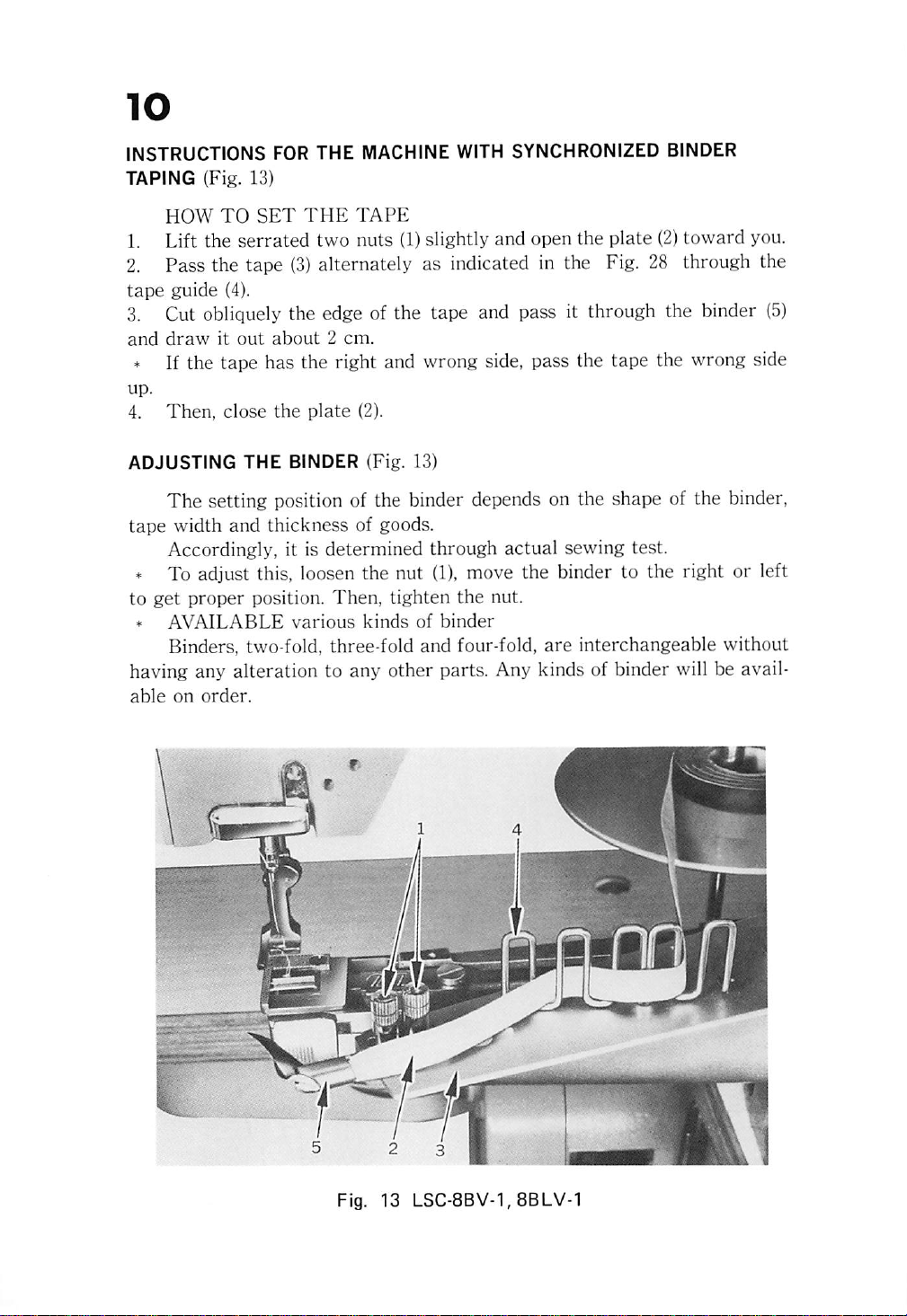
INSTRUCTIONS FOR THE MACHINE WITH SYNCHRONIZED BINDER
TAPING {Fig. 13)
HOW
TO
SET
THE
TAPE
1. Lift the
2. Pass the tape
tape
guide
3. Cut obliquely the edge of the tape and pass it through the binder
and
drawitout
* If the tape has the right and wrong side, pass the tape the wrong side
up.
4.
Then,
serrated
(4).
close
two
nuts
(1)slightly
(3)
alternately as indicated in the Fig. 28 through the
about2cm.
the
plate
(2).
and
open the
plate
(2)
toward
you.
(5)
ADJUSTING
THE
BINDER (Fig. 13)
The setting position of the binder depends on the shape of the binder,
tape
width
and
thickness
of goods.
Accordingly, it is determined through actual sewing test.
* To adjust this, loosen the nut
to
get
*
AVAILABLE
proper
position.
various
Then,
kinds
Binders, two-fold, three-fold and four-fold,
(1),
tighten
of
move the binder to the right or left
the
nut.
binder
are
interchangeable without
having any alteration to any other parts. Any kinds of binder will be avail
able
on
order.
Page 13
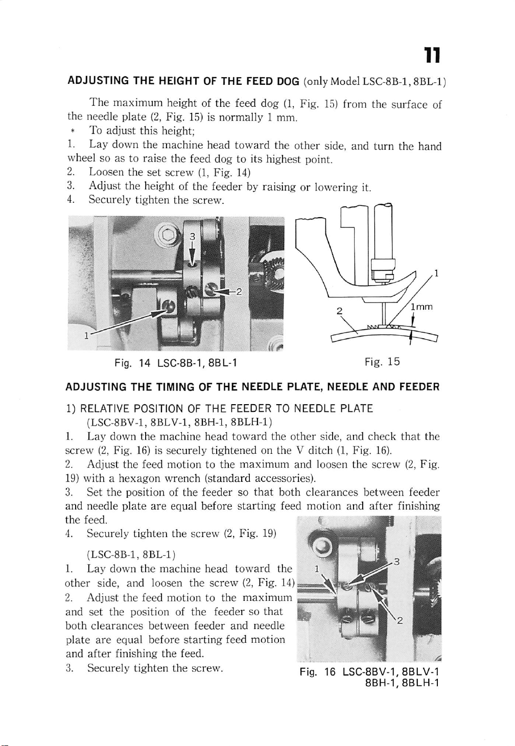
ADJUSTING
The
the needle
» To
1. Lay down the machine head toward the other side, and turn the hand
wheel so as to raise the feed dog to its highest point.
2. Loosen
3.
Adjust the height of the feeder by raising or lowering it.
4. Securely tighten
THE
HEIGHTOFTHE
maximum height of the feed dog
plate
(2, Fig. 15) is
adjust
the
this
set
height;
screw
the
(1, Fig. 14)
screw.
FEED
normally
DOG
(1,
1 mm.
(only
Fig.
Model
15)
LSC-8B4,
from the surface of
8BL-1)
m
Fig.
Fig.
14
LSC-8B-1,8BL-1
15
ADJUSTING
1) RELATIVE POSITION OF
(LSC-8BV-1, 8BLV-1, 8BH-1, 8BLH-1)
1.
Lay
screw
2.
19)
3.
and
4.
1.
other
2.
and
both
plate
and
3.
(2, Fig. 16) is
Adjust
withahexagon
Set
needle
Securely
Lay
side,
Adjust
set
clearances
are
after
Securely
THE
down
the
down
the
the
feed
positionofthe
plate
tighten
the
and
the
feed
the
position
between
equal
finishing
before
tighten
TIMING OF
machine
securely
motion
wrench
are
equal
the
screw
machine
loosen
the
motiontothe
of
the
feeder
starting
the
feed.
the
screw.
THE
THE
head
tightened
to
the
(standard
feeder
before
head
screw
feedersothat
NEEDLE PLATE, NEEDLE AND FEEDER
FEEDER TO NEEDLE PLATE
toward
maximum
so
starting
(2,
Fig.
toward
and
feed
the
other
on
theVditch
and
accessories).
that
both
feed
19)
the 1 J
(2,
Fig.
14)
maximum
needle
motion
side,
(1,
loosen
clearances
motion
and
Fig.
the
and
[ Vj
check
16).
screw
between
after
finishing
^
^ J ^
Fig.
16
LSC-8BV-1,
8BH-1,8BLH-1
that
the
(2,
Fig.
feeder
H|r
BQ
HI
/"
8BLV-1
Page 14

2) THE
POSITION
OF THE
NEEDLE
AND
NEEDLE
HOLE
OF THE
FEEDER
• To adjust this,
est
point
and
•
the
• If
1.
Turning
needle
the
Lay
the
descends
needle
down
turn
the
putaperfect
hand
wheel to
to
the
does
not
the
machine
hand
needle.
center
enter
head
wheel to
lower
of
into
toward
slowly the needle
the
needle
the
center
the
(3, Fig. 14, Fig. 16) is securely tightened on
2.
Remove
3.
Loosen
4.
Holding
as
mayberequiredtoget
5.
Tighten
the
cover
the
screw
the
bottomofthe
the
screw
(5,
(1,
and
Fig.
Fig.
the
close
11)
17)
needle
correct
the
bar
positiontothe
cover.
raise
the
needle
holeofthe
of
the
hole,
other
side,
and
the
V ditch (1, Fig. 16).
rock
frame
(1, Fig. 18),
feeder.
bar,
feeder
check
bartoits
check
whether
or
the
move
high
not.
screw
it
Fig.
normally
upper
18
the
endofthe
measurement
needle
eye
ADJUSTING
*
When
between
the
Fig.
THE
HEIGHT
the
needle
surfaceofthe
17
barisat
OF
THE
needle
its
NEEDLE
lowest
plate
and
BAR
point,
the
12.6 mm (LSC-BBV-l), 12.8 mm (LSC-8B-1), 13.1 mm (LSC-8BLV-1) and
13.3
mm (LSC-8BL-1)
*
To
adjust
1.
Loosen
2. Move
stud
(3,
Fig.
3.
Tighten
NOTE:
this,
the
the
18)toget
the
These
screw
setting
measurements
(2,
Fig.
18)
position of the needle
the
correct
screw.
position.
are
approximate
lowing final adjustments, TIMING
THE
NEEDLE,
are
recommended.
bar
and
needle
standard,
BETWEEN
bar
connecting
accordingly, fol
THE
HOOK AND
is
Page 15

TIMING
BETWEEN
THE
HOOK
AND
THE
NEEDLE
* After settingthe
needle
bar height,confirm as
follows:
Set the stitch length to 0, turn the hand wheel to lower the needle bar to
its lowest point, turn the hand wheel toward you.
raises
When the needle
2 mm (2.5 mm for LSC-8BLV-1, 8BLH-1,
fromthelowestpoint of its travel,normally the hook point
comes
8BL-1)
at the center
line of the needleand the measurement betweenthe hook point andthe upper
endof the
needle
eyeshould be 2mm, further the
clearance
between the hook
point and the needle hollow should be about 0.05 to 0.1 mm.
•
TIMING
1.
Loosen
2.
Adjust
of
its
revolution.
3.
Also
rightorto
4.
After
AND THE CLEARANCE ADJUSTMENT (Fig.
the
two
the
timing. If
adjust
the
the
leftasmay
adjustment,
screws
clearance
(1).
require
require.
securely
earlier,
by
means
tighten
turn
of
the
the
movement
screws.
hook
19)
toward
of
the
the
hook
direction
to
the
m
Page 16

TIMING
BETWEEN
NEEDLE
AND
FEEDER
* During the feeder feeds the material, the needle also moves together
with
the
feeder
*
To
adjust
1.
Remove
2. Loosen
HOW
TO
ADJUST
1.
Turn
pointofhook
2. Pushing the stitch length regulating lever
turn the cam
feeder
rest.
the
this,
the
the
hand
crossed.
(2,
and
feeds
top
screws
wheel
Fig.
the
material.
cover
(2, Fig. 10)
(1, Fig. 21)
toward
21)
and set at the point both the needle and the
and
you to
move
the
the
cam
point of
(4,
Fig.
(2, Fig. 21)
the
11)
needle
and
the
up and down,
3. Tighten the screws securely and close the top cover.
Fig. 21 LSC-8BV-1,8BLV-1
8BH-1,8BLH-1
ADJUSTING
*
ADJUSTMENT
1.
Loosen
THE
the
HEIGHT
BY
screw
2. Raise the presser
OF
THE
PRESSER
THE
PRESSER
(1,
Fig.
10)
sufficiently.
bar
lifter and loosen the
Fig. 21 LSC-8B-1,8BL-1
FEET
BAR
LIFTER
set
screw
{1,
Fig. 22).
3. Move the lifting presser foot (4, Fig. 3) up or down as may be required
soasto
4.
get
Tighten
the
the
correct
screws
height.
securely.
Page 17

* ADJUSTING THE LIFT OF ALTERNATING
PRESSER
FEET
If the height of the lifting presser foot changes, the momentums of the
lifting and vibrating presser footvary,thusthe
er
foot
must
be adjusted.
HOW
TO
ADJUST:
1.
Lower the presser bar lifter, holding the vibrating presser foot
3)
2.
Loosen
downasmay
After
3.
the hexagon screw
be required.
setting
the
position, tighten the screw.
(2,
Fig.
22)
height
ofthe vibratingpress
and movethe presser foot up or
(5,
Fig
TIMING
*
lowering the
feeder
OF
THE
VIBRATING
This
is the normal timing when,
earlier
presser
than
the
bar
needle
PRESSER
turn
FOOT
the
lifter, the vibrating
eye
comes
to,
vibrating presser foot should leave the feeder
the
feeder.
This
hold
the
goods while
stitches.
*
To
adjust
1.
Set
the
2. Loosen
the
cam
(4, Fig. 22)
3.
Tighten
is due to the reason
the
this,
lift of
the
the
the
two
screws
faster
screws.
alternating
that
the vibrating presser foot must tightly
needle is passing
presser
the
feettoequal.
(3, Fig. 22) and adjust the
or
slower
as
maybedesired.
hand
presser
and
when
after
wheel
toward
foot should
the
needle
the needle eye has left
goods for avoiding
rotating
you,
after
reach
raises,
the
the
irregular
position of
Fig.
22
Page 18

16
ADJUSTING
»
Normally,
the
upper
while
bin
1.
2.
left)
3.
1.
2.
3.
tension
4.
raisingofthe
case.
*
For
Loosen
Move
Tighten
*
HOW
Loosen
Loosen
Turn
Tighten
more
(to
THE
thread
the
the
the
TO
ADJUST
the
the
the
tension
lighten
the
THREAD
the
thread
until
needle
controller
stop
stop
(4,
screw.
serrated
screw
the
screw
the
screw
Fig.
THE
(4,
stud
tension,
and
CONTROLLER
controller
needle
and
passingofthe
action
nut
Fig.
on
(3,
Fig.
9) to
the
TENSION
(5,
Fig.9)slightly.
18) slightly.
(6,
Fig.9)slightly
turntothe
the
nut.
spring
reaches
the
9)
right.
OF
to
thread
THE
SPRING
(2,
Fig.9)should
the
goods,
upper
(For
less
SPRING
to
the
right)
withascrew
anditshould
thread
through
action,
left
to
hold
slack
the
moveitto
strengthen
driver.
of
pause
bob
the
the
Page 19

i
©
SEIKO
11-3, Imado 1-chome, Taito-ku, Tokyo 111-8534,
TEL: +81-3-3872-6173,4
FAX:
E-Mail: seikOOOl
www.tctv.ne.jp/selk0001/
SEWING
+81-3-3873-6596
©tctv.ne.jp
MACHINE
(Overseas
group)
CO.,
LTD.
Japan
00093000-(E)
 Loading...